


Ductless Split Heat Pump
Installation Manual
Indoor
AM24LP2VHA
AM36LP2VHA
AM48LP2VHA
AL24LP2VHA
AL36LP2VHA
AL48LP2VHA
AW24LP2VHA
AW36LP2VHA
Outdoor
1U24LP2VHA
1U36LP2VHA
1U48LP2VHA
Nomenclature
T
able of Cont
............................................................................................................................... 2
ents
................................................................................................................... 3
ety ........................................................................................................................................... 4
Saf
Section A - Outdoor Unit Installation ............................................................................................ 7
Section B - Indoor Unit Installation - Wall Mount ......................................................................... 13
Section C - Indoor Unit Installation - Cassette ............................................................................. 17
Section D - Indoor Unit Installation - High ESP Duct ................................................................... 23
Section E - Wir
ed Controller YR-E17 ............................................................................................ 29
Section F - Wireless Remote Controller ....................................................................................... 37
ENGLISH
1 U 24 LP 2 V H A
1 U 18 ES 2 V H A
Unit Type
A = Indoor Unit
1 = Single Zone Outdoor
2 = Two Zone Outdoor
3 = Three Zone Outdoor
4 = Four Zone Outdoor
Nomenclature
Nomenclature
Product Revision
Unit Type
U = Outdoor
B = Casse e Type Indoor
D = High ESP Duct Type Indoor
M=High Static Duct Type Indoor
W = Wall Mount Type Indoor
L = Large Cassette Type Indoor
Nominal Capacity
In Btu/hr (x 1000)
Product Family
- LP:LP=FlexFit Pro Series
System Type
H = Heat Pump
C = Cool Only
Compressor Speed
V = Variable Speed
Voltage
1 = 115V
2 = 230V
PAGE 2
INTRODUCTION
Model
Name
Operating
Range
Power
Supply
Outdoor
Unit
Indoor Unit
Refrigerant
Line
System AW24LP AW36LP AM24LP AM36LP AM48LP AL24LP AL36LP AL48LP
Outdoor
Indoor AW24LP2VH AW36LP2VH AM24LP2VH AM36LP2VH AM48LP2VH AL24LP2VH AL36LP2VH AL48LP2VH
Cooling
Heating
Voltage, Cycle,
Maximum Fuse
Minimum Circuit
Height
Width
Depth
(Ship/Net)-
°F(°C)
°F(°C)
Phase
V/Hz/-
Compressor
Size
A
Amp
A
Dimension:
in (mm)
Dimension:
in (mm)
Dimension:
in (mm)
Weight
(kg)
Dimension:
Height
in (mm)
Dimension:
Width
in (mm)
Dimension:
Depth
in (mm)
Max. External
Static Pressure
1U24LP2VH 1U36LP2VH 1U24LP2VH 1U36LP2VH 1U48LP2VH 1U24LP2VH 1U36LP2VH 1U48LP2VH
0~115
(-18~46)
-4~75
(-20~24)
208-
230/60/7
25.0 30 25.0 30 40 25.0 30 40
21.0 26.0 21.0 26.0 35.0 21.0 26.0 35.0
38 (965) 38 (965) 38 (965) 38 (965) 53 1/8 (1350) 38 (965) 38 (965) 53 1/8 (1350)
37 3/8(950) 37 3/8(950) 37 3/8(950) 37 3/8(950) 37 3/8(950) 37 3/8(950) 37 3/8(950) 37 3/8(950)
14 5/8(370) 14 5/8(370) 14 5/8(370) 14 5/8(370) 14 5/8(370) 14 5/8(370) 14 5/8(370) 14 5/8(370)
202.8/ 176.4
lbs
(92/80)
13 1/4(336) 14 3/8(365) 9 7/8 (250) 9 7/8 (250) 9 7/8 (250) 9 5/8 (246) 9 5/8 (246) 11 3/8 (288)
43 7/8(1115)
9 9/16(243) 10 7/8(275) 25 3/4 (655) 28 3/8 (720) 28 3/8 (720) 33 1/8(840) 33 1/8(840) 33 1/8(840)
NA NA 0.6(150) 0.6(150) 0.6(150) NA NA NA
0~115
(-18~46)
-4~75
(-20~24)
208-
230/60/10
207.2/180.7
(94/82)
51
13/16(1316)
0~115
(-18~46)
-4~75
(-20~24)
208-
230/60/8
202.8/ 176.4
(92/80)
37 5/8 (957) 59 (1500) 59 (1500) 33 1/8(840) 33 1/8(840) 33 1/8(840)
0~115
(-18~46)
-4~75
(-20~24)
208-
230/60/11
DC Inverter Driven Rotary
207.2/180.7
(94/82)
0~115
(-18~46)
-4~75
(-20~24)
208-
230/60/13
260.1/231.5
(118/105)
0~115
(-18~46)
-4~75
(-20~24)
208-
230/60/9
202.8/ 176.4
(92/80)
0~115
(-18~46)
-4~75
(-20~24)
208-
230/60/12
207.2/180.7
(94/82)
(-18~46)
(-20~24)
230/60/14
260.1/231.5
(118/105)
in.W.G(Pa)
Drainpipe Size
in
O.D.
Internal
Condensate
Max. Drain-Lift
height
in(mm)
Grill Model NA NA NA NA NA PB-950KB PB-950KB PB-950KB
Weight
(Ship/Net)-
lbs
(kg)
Connections Flare Flare Flare Flare Flare Flare Flare Flare
Liquid O.D.
Suction O.D.
Factory Charge
in
in
Oz
Maximum Line
Length
Ft / m
Maximum Height
Ft / m
NA NA 1 1/4 1 1/4 1 1/4 1 1 1
NA NA Standard Standard Standard Standard Standard Standard
NA NA 27 9/16(700) 27 9/16(700) 27 9/16(700) 39 3/8 (1000) 39 3/8 (1000) 39 3/8 (1000)
45.4/37.5(20.
6/17)
3/8 3/8 3/8 3/8 3/8 3/8 3/8 3/8
5/8 5/8 5/8 5/8 5/8 5/8 5/8 5/8
88.2 88.2 88.2 88.2 131 88.2 88.2 131
165 (50) 165 (50) 165/50 165/50 230/75 165/50 165/50 230/75
100/30 100/30 100/30 100/30 100/30 100/30 100/30 100/30
55.1/46.3(25.
5/21)
81.1/68.8
(36.8/31.2)
130.1/121.3
(59/55)
132.3/114.6
(60/52)
79.4/68.3
(36/31)
79.4/68.3
(36/31)
83.8/70.5
ENGLISH
0~115
-4~75
208-
(38/32)
INTRODUCTION
PAGE 3
SAFETY OVERVIEW
Read These Safety Precautions
Be sure to read the safety precautions before conducting work. The items are classified into “Warning” and “Caution.” The
“Warning" items are especially important since they can lead to death or serious injury if not followed closely. Under certain
conditions, the "Caution" items can also lead to accident or injury if they are not followed. Therefore, be sure to observe all
ENGLISH
safety precautions listed here.
∆ This symbol means be careful when doing this procedure or touching this equipment.
ᴏ This symbol indicates a prohibited action.
• This symbol means that an action must be taken; the action will be listed next to the symbol.
After the repair work is complete, be sure to conduct a test operation to ensure that the equipment operates properly;
explain the safety precautions for operating the equipment to the customer.
Warning
Disconnect the power cable from electrical supply
before disassembling equipment for repair.
If the refrigerant discharges during the repair work,
DO NOT touch the discharging refrigerant. The
refrigerant can cause frostbite.
Before disconnecting the suction or discharge
pipe of the compressor at the brazed connections,
recover the refrigerant in a well-ventilated area. If
refrigerant remains inside the compressor, the
refrigerant or the refrigerating machine oil will
discharge when the pipe is disconnected and may
cause injury.
If the refrigerant leaks during the repair work,
ventilate the area. The refrigerant can generate
toxic gases when it contacts ames.
The step-up capacitor supplies high-voltage
electricity to the electrical components of the
outdoor unit. Be sure to discharge the capacitor
completely before conducting repair work. A
charged capacitor can cause electrical shock.
Be sure to use parts listed in the service parts
of the applicable model and appropriate tools to
conduct repair work. Never attempt to modify
the equipment. The use of inappropriate parts or
tools can cause electrical shock, excessive heat
generation, or re.
When relocating the equipment make sure that
the new installation site has sufficient strength to
withstand the weight of the equipment. If the new
installation site does not have sucient strength
and if the installation work is no
securely, the equipment can fall and cause injury.
t conducted
Be sure to install the product correctly by using the
standard installation frame provided. Incorrect use
of the installation frame and improper installation
can cause equipment to fall, resulting in injury.
Do not repair the electrical components with wet
hands. Working on equipment with wet hands can
cause electrical shock.
Do not clean the equipment by splashing water.
Washing the unit with water can cause an electrical
shock.
Make sure that the unit is grounded when reparing
the equipment in a wet or humid place to avoid
electrical shocks.
Be sure to turn o the power switch when cleaning
the equipment; the internal fan rotates at a high
speed and may cause injury.
Do not tilt the unit when removing it. Water inside
the unit can spill, wetting the oor.
Be sure to check that the refrigeration cycle section
has cooled down suciently before conducting
repair work. Working on the unit when the
refrigerating cycle is hot can cause burns.
Use the brazing equipment in a well-ventilated
place. Using the brazing equipment in an enclosed
room can cause oxygen deficiency.
Be sure to use a dedicated power circuit for the
equipment; follow appropriate technical standards
for the electrical equipment, the internal wiring
regulations, and the instruction manual for
installation when conducting electrical work.
Insucient power circuit capacity and improper
electrical work can cause an electrical shock or re.
PAGE 4
INTRODUCTION
SAFETY OVERVIEW
Read These Safety Precautions
Be sure to use the specied cable to connect
between the indoor and outdoor units. Make the
connections securely and route the cable properly
so that there is no force pulling the cable at the
connection terminals.
When connecting the cable between the indoor and
outdoor units make sure that the terminal cover
does not lift o or dismount because of the cable.
If the cover is not mounted properly, the terminal
connection section can cause an electrical shock,
excessive heat generation, or re.
Do not damage or modify the power cable.
Damaged or modied power cables can cause
electrical shock or re. Placing heavy items on the
power cable and heating or pulling the power cable
can damage the cable.
Do not introduce air into the refrigerant system. If
air enters the refrigerant system, an excessively
high pressure results, causing equipment damage
and injury.
If the refrigerant leaks, be sure to locate the leak
and repair it before charging the system with
additional refrigerant. If the leak cannot be located
and the repair work cannot be stopped, be sure to
perform pump-down and close the service valve to
prevent the refrigerant from leaking into the room.
The refrigerant itself is harmless, but it can
generate toxic gases when it contacts a heat
source such as another appliance or an open flame.
When replacing the remote control battery, be
sure to safely dispose of the battery.
Do not install the equipment in a place where
there is a possibility of combustable gas leaks. If
combustible gas leaks and remains near the unit, it
may cause a re.
Be sure to install the packing and seal on the
installation frame correctly. If the packing and
seal are not properly installed, water can spill out,
wetting furniture and the oor.
ENGLISH
Replace power cables and lead wires if they are
scratched or deteriorated. Damaged cable and
wires can cause electrical shock, excessive heat
generation, or re.
Check to see if the parts are mounted correctly,
that the wires are connected correctly, and that
connections at soldered or crimped terminals are
secure. Improper installation and connections can
cause excessive heat generation, electrical shock,
and re.
If the installation platform or frame has deteriorated
or corroded, replace it. Corroded platform or frames
can cause the unit to fall, resulting in injury.
Check to make sure that the equipment is grounded.
Repair it if it is not properly grounded. Improper
grounding can cause an electrical shock.
Be sure to measure the installation resistance of
the repair. Be sure that the resistance is 1 M ohm
or higher. Faulty installation can cause an electric
shock.
Be sure to check the drainage of the indoor unit after
the repair. Faulty drainage can cause a water leak
from indoor unit and could cause property damage.
Important Safety Related
Installation Information
Indoor Clearances: If noncompliant may lead to temperature
control complaints.
Wire Sizing: If noncompliant may lead to communication errors
and inverter irregular operation.
Splices in Field Wiring: Splices between the wires that connect
between the outdoor and indoor unit should be avoided.
Sealing Penetrations: If penetrations at back of unit are not
sealed, unconditioned air may be drawn into the back of the
indoor wall mount unit. Temperature control and capacity
complaints may occur.
INTRODUCTION
PAGE 5

[This page intentionally left blank.]
Section A - Outdoor Unit Installation
Step 1 - Installation of the Outdoor Unit
Attaching Drain Elbow to Outdoor Unit
(Heat Pump models only)
1.1
Step - 1.1
If attaching the supplied drain elbow to the outdoor unit,
do so prior to attaching the refrigerant lines and wiring.
Extension piping to attach to this tting is eld supplied.
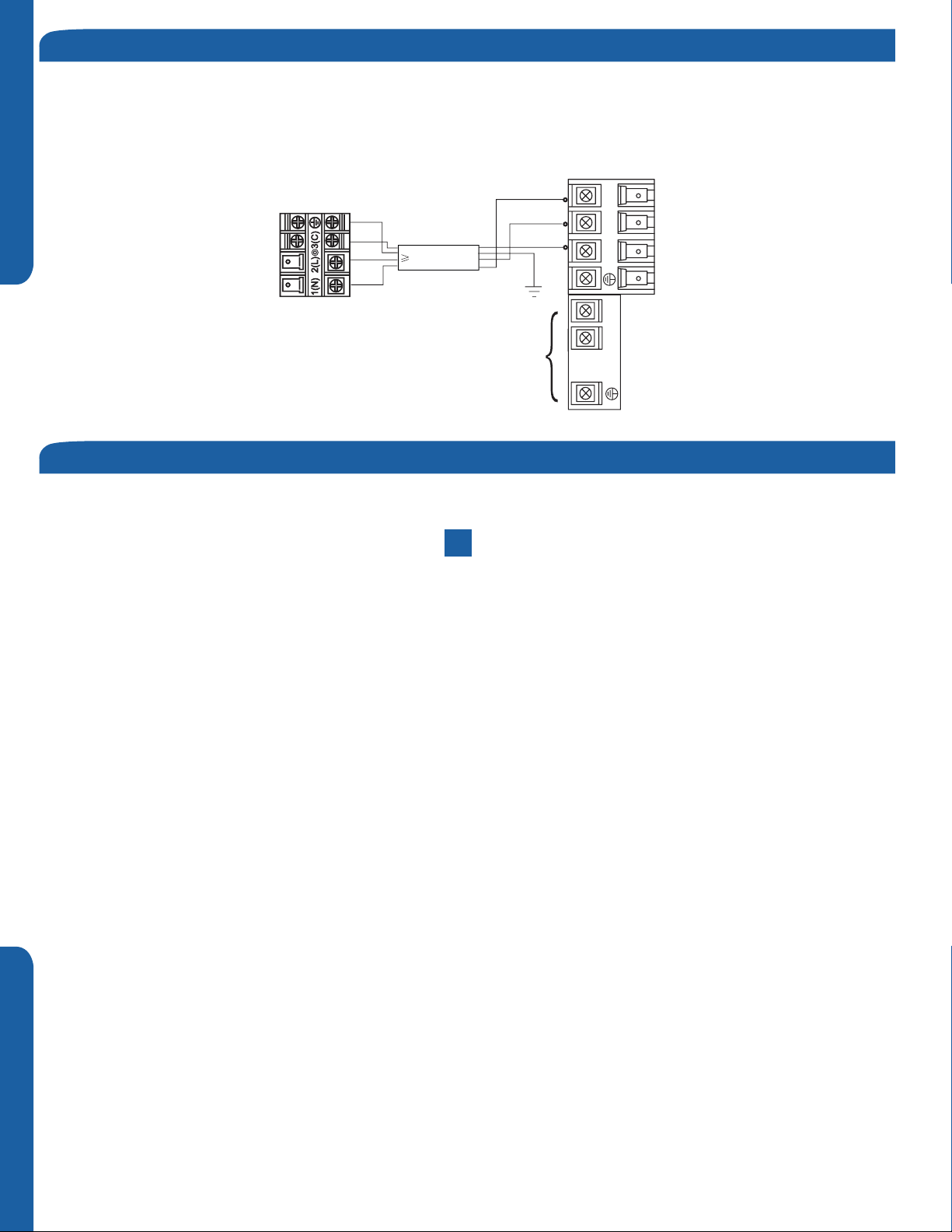
Electrical Connections for the Outdoor Unit
1.2
Step - 1.2
Remove the cover plate of the outdoor unit to expose the
terminal block connections.
1.3
Step - 1.3
Connect the wiring for both the power source and indoor
wiring.
Wire the system according to applicable national / local
codes.
Verify that the wiring connections for the indoor unit match
wire for wire.
(1-1, 2-2, 3-3, Gnd-Gnd). Failure to wire the system correctly
may lead to improper operation or component damage.
Step 1.1
Step 1.3
ENGLISH SECTION A
Step1.2
Step 1.4
1.4
Step - 1.4
Replace the cover plate.
Step 2 - Connecting the Indoor Unit
*See indoor section A, B, or C for electrical connections.
Piping
The standard lineset length is 25ft. If the installation length is
different, adjust the refrigerant charge by 0.5oz/ft.for the
24k,36k,42k and 48k model. (Illustration 4)
Cut the lineset to length, are and attach the piping to the
outdoor unit valves.
Torque the ttings to the specications shown in the torque
chart.
2.1
Step - 2.1
Refrigerant piping connections at the indoor unit are made
utilizing flare joints. Follow standard practices for creating
pipe flares. When cutting and reaming the tubing, use caution
to prevent dirt or debris from entering the tubing. Remember
to place the nut on the pipe before creating the flare.
CAUTION
Outdoor unit
Outdoor unit
Outdoor unit
Indoor unit
B
A
Max. Elevation: A Max.
●
= 100ft / 30m (24k / 36k)
In case the height of A is more than
●
Oil trap
B
Indoor unit
A
15ft / 5m, an oil trap should be
installed every 16-23ft /5-7m
●
Max. Length: B Max
= 165ft / 50m (24k / 36k)
B
Indoor unit
A
Illustration 4
2.2
Step - 2.2
To join the lineset piping together, directly align the piping
are to the tting on the other pipe, then slide the nut onto
the tting and tighten. Misalignment may result in a leaking
connection.
INSTALLATION
Step 2.2Step 2.1
PAGE 7
2.3
Step - 2.3
Two wrenches are required to join the are connections, one
standard wrench, and one torque wrench. See Table 1 for the
specic torque per piping diameter.
Forced fasteningwithout carefulcentering may
damagethe threads and cause a leakageofgas.
Pipe Diameter(ǿ)Fastening torque
Liquid side6.35mm(1/4") 18N.m/13.3Ft.lbs
Liquid/Gas side9.52mm(3/8") 42 N.m/30.1Ft.lbs
Gasside12.7mm(1/2") 55N.m/40.6Ft.lbs
Gasside15.88mm(5/8") 60 N.m/44.3Ft.lbs
ENGLISHSECTION A
Half union
Spanner
Flarenut
Torque wrench
Table 1
Step 3 - Leak Test and Evacuation
Leak Test
Hazard of Explosion! Never use an open flame to detect
refrigerant leaks.. Explosive conditions may occur. Use a leak
test solution or other approved methods for leak testing.
Failure to follow recommended safe leak test procedures
could result In death or serious injury or equipment or
property damage.
Use only dry nitrogen with a pressure regulator for
pressurizing unit. Do not use acetylene, oxygen or
compressed air or mixtures containing them for pressure
testing. Do not use mixtures of a hydrogen containing
refrigerant and air above atmospheric pressure for pressure
testing as they may become flammable and could result in
an explosion. Refrigerant used as a trace gas should only be
mixed with dry nitrogen for pressurizing units. Failure to
follow these recommendations could result in death or
serious injury or equipment or property damage.
Step 2.3
Step 3.1 Step 3.2
3.1
Step - 3.1
Using a tank of nitrogen with attached regulator, charge the
system with 150 PSIG of dry nitrogen. Use adapter AD-87
(field supplied) to connect to the service valve. Check for
leaks at the flare fittings using soap bubbles or other
detection methods. If a leak is detected, repair and recheck.
If no leaks are detected, proceed to evacuate the system.
System Evacuation
3.2
Step - 3.2
Attach a manifold gauge, micron gauge, and vacuum pump
to the suction line port using adapter AD-87 (eld supplied).
(Illustration 5)
Evacuate the system to 350 microns.
Close the vacuum pump valve and check the micron
gauge. If the gauge rises above 500 microns in 60 seconds,
evacuation is incomplete or there is a leak in the system. If
the gauge does not rise above 500 microns in 60 seconds,
evacuation is complete.
Illustration 5
PAGE 8
INSTALLATION
3.3
Step - 3.3
Remove the adapter and hose connection from the
suction line port, and replace the cap. Hoses should not be
removed and service valves should not be opened until any
additional refrigerant needed for a refrigerant line longer
than 25 ft. has first been added.
3.4
Step - 3.4A & 3.4B
Remove the cap from the liquid line valve. Using the hex
wrench, open the valve, then replace and tighten the cap.
3.5
Step - 3.5A & 3.5B
Remove the cap from the suction line valve. Using the hex
wrench, open the valve, then replace and tighten the cap.
3.6
Step - 3.6
Wrap the lineset, drain line, and wiring starting at the bottom
of the bundle with an overlap type wrap, concluding at the
piping hole. Use a sealant to seal the piping hole opening
to prevent weather elements from entering the building.
(Illustration 6)
Step 3.3 Step 3.4A
Step 3.4B
Step 3.5A
ENGLISH SECTION A
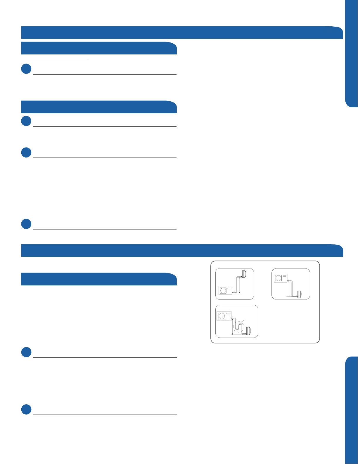
Verify the condensate drain line has a constant pitch
downward for proper water ow. There should be no kinks
or rises in the tubing which may cause a trapping eect
resulting in the failure of the condensate to exit the piping.
Step 3.5B
It becomes
high midway.
Theendis immersed in water.
It waves.
Thegap with the
ground is too small
Illustration 6
Step 3.6
Lessthan
5cm
Thereisthe bad
smellfrom a sewer
INSTALLATION
PAGE 9
Step 4 - Charging
See Steps 5.2 - 5.5 for evacuating the system prior to
charging. The standard lineset length is 25ft. If the
installation length is different, adjust the refrigerant charge
by .5 oz / ft. for the 24K, 36K and 48K model. (Step 4 Illustration 4)
ENGLISHSECTION A
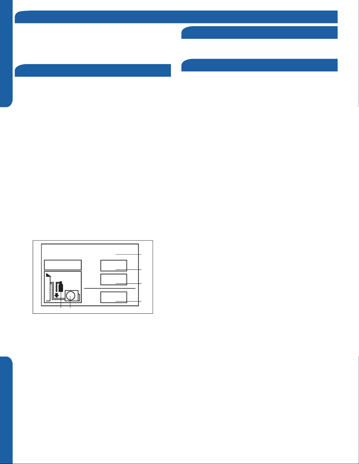
This product contains uorinated greenhouse gases covered
by the Kyoto Protocol. Do not vent into the atmosphere.
Refrigerant type: R410A
GWP* value: 1975
GWP = global warming potential
Please ll in with indelible ink,
• 1 the factory refrigerant charge of the product
• 2 the additional refrigerant amount charged in the eld and
• 1+2 the total refrigerant charge on the refrigerant charge
label supplied with the product.
The lled out label must be adhered in the proximity of the
product charging port (e.g. onto the inside of the stop valve
cover).
A - contains uorinated greenhouse gases covered by the
Kyoto Protocol
B - factory refrigerant charge of the product: see unit name
plate
C - additional refrigerant amount charged in the eld
D - total refrigerant charge
E - outdoor unit
F - refrigerant cylinder and manifold for charging
Refrigerant Charge Label
System Test
Using the instruction manual, show the customer how to
properly use and care for the equipment.
Check Items for Test Run
Put check mark √ in boxes
No refrigerant leaks from line sets or other connections?
Are the linesets insulated properly?
Are the connecting wirings of indoor and outdoor firmly
inserted to the terminal block?
Is the connecting wiring of indoor and outdoor rmly
connected?
Is condensate draining correctly?
Is the indoor unit securely attached?
Is power source voltage correct according to local code?
Is there any noise?
Is the lamp normally lighting?
Are cooling and heating (when in heat pump) performing
normally?
Is the operation of room temperature sensor normal?
Contains fluorinated greenhouse gases
covered by the Kyoto Protocol
R410A
2
1=
2=
oz
oz
1
1+2=
FE
oz
A
B
C
D
PAGE 10
INSTALLATION
Section 5 - Explaining Operation to the End User
Protecti on wa lls
• Using the OPERATING INSTRUCTIONS, explain to the user how to use the air conditioner (the remote controller, removing
the air lters, placing or removing the remote controller from the remote controller holder, cleaning methods, precautions for
operation, etc.)
• Recommend that the user read the OPERATING INSTRUCTIONS carefully.
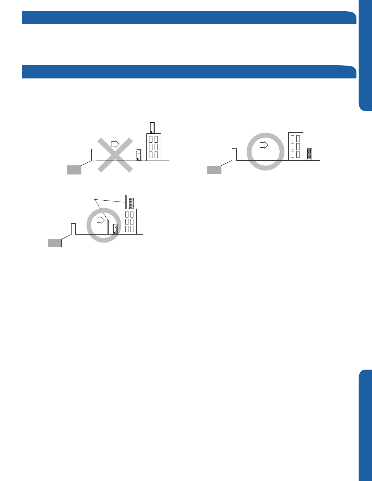
Section 6 - Seacoast Application
• The outdoor unit should be installed at least ½ mile away from the salt water, including seacoasts and inland waterways. If
the unit installed from ½ mile to 5 miles away from the salt water, including seacoasts and inland waterways, please follow the
installation instruction below.
• Install the outdoor unit in a place (such as near buildings etc.) where it can be protected from sea breeze which can damage
the outdoor unit.
ODU
ENGLISH SECTION A
Sea breeze
Sea
ODU
Sea breeze
ODU
Sea
• If you cannot avoid installing the outdoor unit by the seashore, construct a protection wall around it to block the sea breeze.
• A protection wall should be constructed with a solid material such as
concrete to block the sea breeze and the height and the width of the wall
ODU
should be 1.5 times larger than the size of the outdoor unit. Also, secure
over 28 in (700mm) between the protection wall and the outdoor unit for
Sea
Sea breeze
ODU
exhausted air to ventilate.
• Install the outdoor unit in a place where water can drain smoothly.
• If you cannot nd a place satisfying above conditions, please contact manufacturer. Make sure to clean the sea water and the
dust on the outdoor coil.
INSTALLATION
PAGE 11

[This page intentionally left blank.]
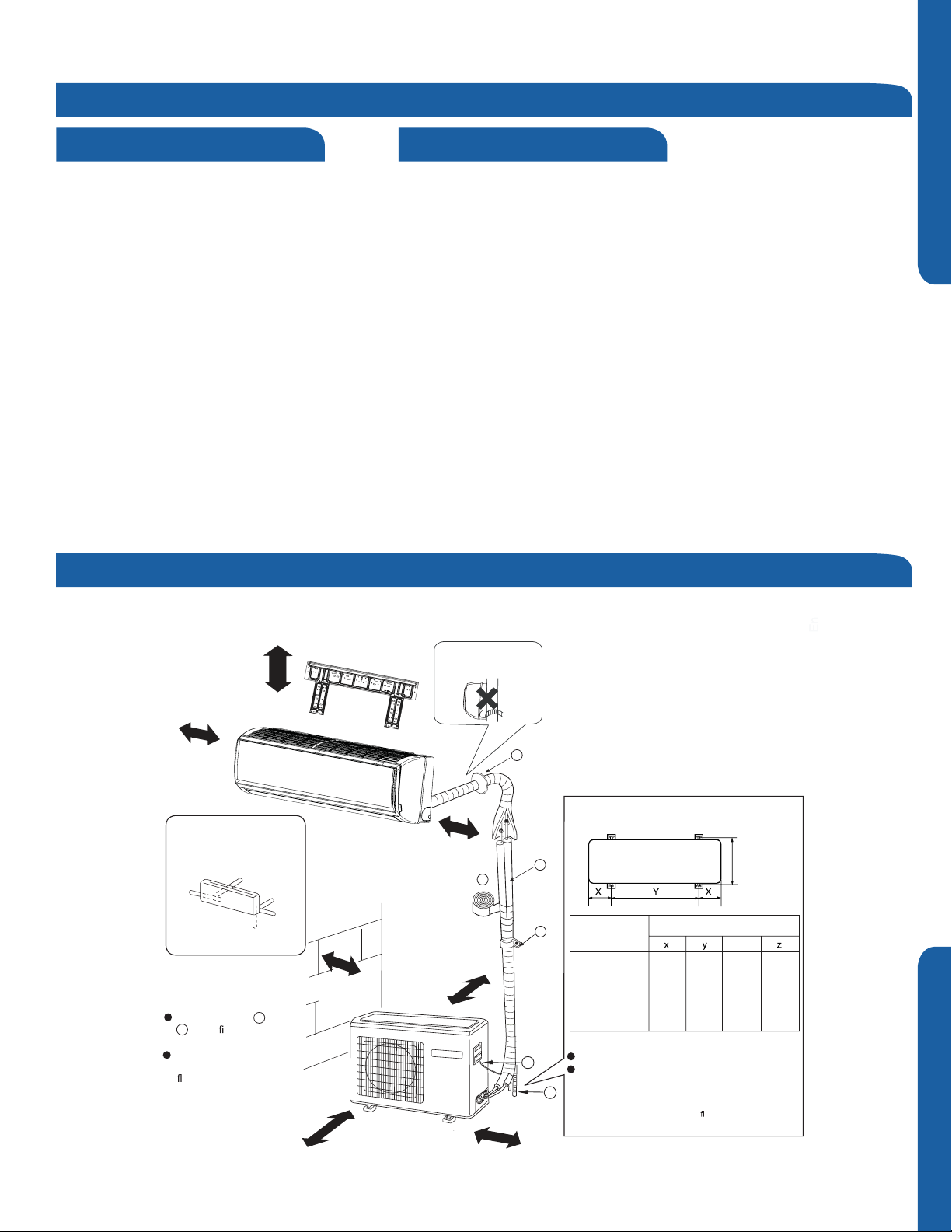
Section B - Indoor Unit Installation - Wall Mount
Required Tools for Installation
• Drill
• Wire Snipper
• Hole Saw 2 3/4”
• Vacuum pump
• Soap-and-water solution or gas leakage
detector
• Torque wrench
• 17mm, 22mm, 26mm
• Tubing cutter
• Flaring tool
• Razor knife
• Measuring tape
• Level
• Micron gauge
• Nitrogen
• Mini-Split AD-87 Adapter (1/4” to 5/16”)
• A - Non-adhesive Tape
• B - Adhesive Tape
• C - Saddle (L.S.) with screws
• D - Electrical wiring
• E - Drain hose (Included)
• F - Insulation
• G - Piping hole cover (Included)
Step 1 - Preparation
Procedure for Selecting the Location
• Choose a place solid enough to bear the
weight and vibration of the unit and where
the operation noise will not be amplied.
• Choose a location where the hot air
discharged from the unit or the operation
noise and will not cause a nuisance to the
user.
• There must be sucient space for
carrying the unit into and out of the site.
• There must be sucient space for air
passage and no obstructions around the
air inlet and air outlet.
• The site must be free from the possibility
of ammable gas leakage in a nearby
place.
• Install units, power cords and inter-unit
cables at least 10ft away from television
and radio sets. This is to prevent
interference to images and sounds.
(Noise may be heard even if they are more
than 10ft away depending on radio wave
conditions.)
ENGLISH SECTION B
Clearances of Indoor and Outdoor Units
This picture is for reference only. Your product may look dierent. Read this manual before installation. Explain the operation of the unit to the user according to
this manual.
The models adopt HFC free refrigerant R410A
Attention must be paid to
more than 4in.
more than
4in.
Arrangement of piping
directions
Rear left
Left
Below
The marks from to
G
in the
name of the parts.
The distance between
the indoor unit and the
than 6 feet.
gure are the
oor should be more
Rear
right
Right
A
more than 4in.
the pitch of drain hose
more than 4in.
more than 4in.
G
Floor fixing dimensions of the outdoor unit
(Unit: inch)
eet t
23 5/8”
he l
Z
6 7/8”
ocal code.
16”
A
F
C
Fixing of outdoor unit
D
E
1 2
Model
1U24/36/42/48
LP2VHA
Anchor the outdoor unit to the pad.
When ins
he i
wall, t
Dimensions(inches)
1 x2
6 7/8”
talling the outdoor unit on a roof or a outside
hould m
nstallation s
more than 24in.
more than 6in.
INSTALLATION
PAGE 13

Step 2 - Installation of Wall Mount Type Indoor Unit
Attaching the Mounting Plate to the Wall
2.1
Step 2.1
ENGLISHSECTION B
Using a stud sensor, locate and mark the stud positions in the
wall where the indoor unit is to be mounted.
2.2
Step 2.2
Place the mounting plate on the wall in the desired location
taking into account the minimum clearances necessary for
proper operation.
Using a level, verify the mounting plate is horizontal and mark
the screw locations.
2.3
Step 2.3
Screw the mounting plate to the wall.
Step 2.1
Step 2.2
The piping for the indoor unit may be routed to the unit from
one of several directions. Left, Left Rear, Right, Right Rear, or
Below (Illustration 1).
2.4
Step 2.4
Knockouts are provided on the case for Left, Right, and Right
Below.
Drilling the hole through the wall for left rear or right rear
installation
2.5
Step 2.5A & 2.5B
Measure and mark the location where the piping hole is to be
drilled.
2.6
Step 2.6
Drill the piping hole using a hole saw of the correct diameter.
Angle the drill with a downward pitch to the outside wall so
that the outside hole will be ¼” lower than the inside hole,
giving the hole the proper angle for condensate drainage.
2.7
Step 2.7
Install the piping hole cover ange at the hole opening on the
inside wall.
NOTE: The cover ange may require modication to t
properly behind the wall unit housing.
2.8
Step 2.8A & 2.8B
Bundle the refrigerant piping, drain piping and wiring with
tape and pass the bundle through the piping hole.
NOTE: When bundling the power cable, leave sucient length
available in the indoor unit to make the connections to the
terminal block.
Step 2.3
Step 2.5A
Step 2.6
Step 2.8A
Piping Exit Options
Left
Step 2.4
Step 2.5B
Step 2.7
Step 2.8B
Rear left
Rear
right
PAGE 14
Right
Below
Illustration 1
INSTALLATION

Outdoor unit
Mounting the Indoor Unit Onto the Wall Plate
2.9
Step 2.9
With the top of the indoor unit closer to the wall, hang the
indoor unit on the upper hooks of the mounting plate. Slide
the unit slightly side to side to verify proper placement of the
indoor unit on the mounting plate. Rotate the lower portion
of the indoor unit to the mounting plate, and lower the unit
onto the lower hooks of the mounting plate. (Illustration 2)
Verify the unit is secure.
2.10
Step - 2.10
Slightly raise the entire unit vertically, pull the lower portion
of the unit o the lower hooks of the mounting plate and
away from the wall, then lift the upper portion of the unit o
the upper hooks of the wall plate.
Electrical Connections for the Indoor Unit
2.11
Step - 2.11A & 2.11B
To make the electrical connections for the indoor unit, two
cover plates must be removed. Raise the front cover to
access the screws to remove these covers.
2.13
Step - 2.13
Access the four conductor cable through the cover plate
opening and make the wiring connections noting the wire
color used on each terminal. The color of each wire must
match the same positions on the terminal block of the
outdoor unit. (Illustration 3)
Step 2.9
mounting plate
Illustration 2
Step 2.11A
ENGLISH SECTION B
Step 2.10
Step 2.11B
Failure to wire the system correctly may lead to improper
operation or component damage.
2.14
Step - 2.14A & 2.14B
After the terminal block wiring is completed, replace both
cover plates.
Note: Wall mount unit ships with HG remote controller. See
Section F for more information.
Step 2.12
Indoor unit
Step 2.13A
3wire 14AWG
Control Wiring
Power
Wiring
Step 2.13B
Illustration 3
Indoor Wall Unit Installation Complete
1
(
N
)
2
(L
)
3
(
C
)
1
(
N
)
2
(
L
)
3
(
C
)
INSTALLATION
PAGE 15

[This page intentionally left blank.]
Section C - Indoor Unit Installation - Cassette
Introduction - Overview
Cassette Product Information
The Cassette Indoor Air Handler ships consisting of a
cassette assembly and operational louver. The Cassette
Indoor Unit is operated via a factory supplied remote
control. Wired controller is optional.
The Cassette unit will install between standard dropped
brackets that are located at all four corners of the cassette
assembly.
The Cassette unit receives 230 volt line voltage from a
connection at the outdoor condensing unit. T
requirement for independent line voltage connections.
The cassette unit has a built in condensate pump and
Cassette unit. This hose connects the cassette
condensate drain outlet to the building's condensate drain
system.
The motorized louver is controlled via the remote control.
The louver has indicator lights that communicate function
and diagnostic information to the user and service technician.
here is no
Wired Controller is
Optional
Built-in Condensate
Pump and Float Switch
ENGLISH
Factory Supplied Remote
See Section F for more information
Outside Air
Mounting Hangers
Optional fresh air can be piped into the cassette assembly.
The knockout is located on the side of the cassette assembly.
entering the cassette. A 4” galvanized pipe should be used to
pipe in the fresh air.
Included with the cassette unit is factory provided insulating
tape. This tape should be placed over the refrigerant piping
connections at the indoor unit to prevent sweating.
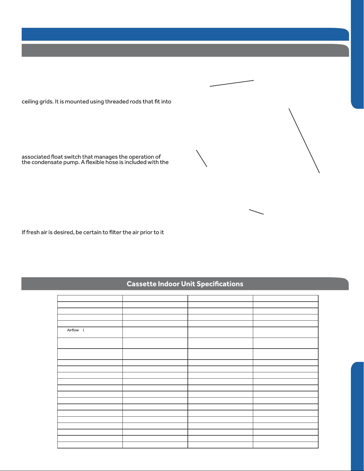
Indoor AL24LP2VHA AL36LP2VHA AL48LP2VHA
Rated Cooling Capacity Btu/hr 24,000 35,000 45,000
Rated Heating Capacity Btu/hr 27,300 36,500 49,000
Voltage, Cycle, Phase V/Hz/-
Fan Speed Stages 4+Auto 4+Auto 4+Auto
Turbo/High/Med/Low/
Quiet) CFM
Motor Speed ( Turbo/High/Med/
Indoor Sound Level dB (Turbo/High/
Chassis Dimension: Height in (mm)
Chassis Dimension: Width in (mm)
Chassis Dimension: Depth in (mm)
Grill Dimension: Height in (mm)
Grill Dimension: Width in (mm)
Grill Dimension: Depth in (mm)
Weight (Ship/Net)- lbs (kg)
Drainpipe Size O.D. in 1 1/4 1 1/4 1 1/4
Internal Condensate Pump Standard Standard Standard
Max. Drain-Lift height in(mm)
Low/Quiet) RPM
Med/Low/Quiet)
Grill Model
Connections Flare Flare Flare
Liquid O.D. in 3/8 3/8 3/8
Suction O.D. in 5/8 5/8 5/8
208/230/60/1 208/230/60/1 208/230/60/1
740/630/480/400 990/900/776/700 1147/941/847/705
500/400/300/250
36/33/29/26
PB-950KB
9 5/8 (246)
33 1/8(840) 33 1/8(840) 33 1/8(840)
33 1/8(840)
2 (50)
37 3/8 (950)
37 3/8 (950)
79.4/68.3 (36/31)
39 3/8 (1000) 39 3/8 (1000) 39 3/8 (1000)
650/550/450/400 750/650/500/400
45/42/38/34
PB-950KB PB-950KB
9 5/8 (246)
33 1/8(840)
2 (50)
37 3/8 (950)
37 3/8 (950)
79.4/68.3 (36/31)
41/36/33/31
11 3/8 (288)
33 1/8(840)
2 (50)
37 3/8 (950)
37 3/8 (950)
83.8/70.5 (38/32)
SECTION C
INSTALLATION
PAGE 17

Introduction - Overview
Fresh Air Intake Option
The cassette has a marked area to cut out if outside air is
desired. The piping connection should be made with a 4 inch
ENGLISHSECTION C
entry into the cassette.
Fresh air
knock out
Condensate Handling
The Cassette unit has a built in condensate pump and water
level safety switch. There is no option for gravity drain. The
condensate pump is rated to lift water up to 24” from the
point of discharge on the cassette assembly.
Electrical Power
Follow all local codes and regulations when installing electrical
wiring.
Route required electrical power to area where cassette is to
be located. Maintain at least a 10 foot separation between TV
and Radio wiring and the power to the indoor unit.
14 Gauge AWG stranded wire should be used to make the
electrical connection between indoor and outdoor units.
This wiring will serve to power the indoor unit and establish a
communication link between indoor and outdoor units.
The wiring is connected at the indoor unit electrical terminal
blocks screws 1, 2, 3 and ground. There should be no
splices in the wires connected to terminals 1 or 3 as these
serve as communication signal wires and electrical power
power to the indoor unit, break wire 2 only.
The cassette unit comes with a grey connection hose with
clamp. This hose is connected to the cassette assembly
discharge hose port. The other end of the hose is sized to
accept 3/4 “ PVC piping.
here:
12 in. below
3-5 ft.
11 in. under
8.6 in.
8.6 in.
19.6 in. below
Air Delivery Clearances
Be certain to maintain proper clearances around the
Standard clearances for cassette air handlers require 5
feet of clearance in each direction. There should be 8 feet
of clearance from the face of the cassette louver to the
temperature control problems.
Service and Maintenance Clearances
Make sure there are adequate clearances for future
maintenance and service. Allow enough room to access the
condensate pump assembly and the electrical control box.
1 ft.
5 ft.
8 ft. Over
5 ft.
PAGE 18
INSTALLATION

Step 1 - Preparation
• Drill
• Wire Snipper
• Hole Saw 2 3/4”
• Vacuum pump
• Soap-and-water solution or gas leakage
detector
• Torque wrench
• 17mm, 22mm, 26mm
• Tubing cutter
• Flaring tool
• Razor knife
• Measuring tape
• Level
• Micron gauge
• Nitrogen
• Mini-Split AD-87 Adapter (1/4” to 5/16”)
• A - Non-adhesive Tape
• B - Adhesive Tape
• C - Saddle (L.S.) with screws
• D - Electrical wiring
• E - Drain hose (Included)
• F - Insulation
• G - Piping hole cover (Included)
Procedure for Selecting the LocationRequired Tools for Installation
• Place above the ceiling where you have
enough space to position the unit.
• Place where the drainage pipe can be
properly positioned.
• Place where the inlet and outlet air of the
indoor unit will not be blocked.
• Do not install the unit in a place with
heavy oil or moisture (e.g. - kitchens and
workshops)
• Do not install in a location with destructive
gas (such as sulfuric acid gas) or pungent
gas (thinner and gasoline) are used or
stored.
• Choose a place solid enough to bear the
weight and vibration of the unit and where
the operation noise will not be amplied.
• Install where there are no expensive items
like a television or piano below the indoor
unit.
• Leave enough space for maintenance.
• Install at least 3 ft. away from televisions
and radios to avoid interference.
ENGLISH SECTION C
Note:
1) R-410A refrigerant is a safe, nontoxic and
nonammable refrigerant. However, if
there is a concern about a dangerous level
of refrigerant concentration in the case of
refrigerant leakage, add extra ventilation.
Threaded Rod Mounting Information
The Cassette unit should be mounted to the building
structure using threaded rods. The threaded rods should
have washers and nuts to allow the height and level of the
cassette to be adjusted.
The threaded rods and attachment brackets are eld supplied
items. The materials required for mounting to the brackets
on the cassette assembly include:
4- 3/8” Threaded Rods
4- Mounting Brackets
8- Washers
8- Nuts (Double nut the assembly as shown)
INSTALLATION
PAGE 19

Step 2 - Installation of the Cassette Unit
Step By Step Guide To Cassette Installation
2.1
Step 2.1
Use cardboard template to locate center point of cassette for
mounting. Use a plumb bob and string to position cassette
ENGLISHSECTION C
by referencing center hole of template. Mark the mounting
positions of the threaded rods using the guides on the
cardboard template.
2.2
Step 2.2
Install threaded rods to structure using appropriate
fasteners.
2.3
Step 2.3
Lift the cassette and position the threaded rods into the 4
mounting clips on each corner of the cassette unit.
2.4
Step 2.4
Using a level, adjust the nuts on the threaded rods to obtain a
level reading across the bottom of the cassette unit.
2.5
Step 2.5A & 2.5B
Prior to routing the refrigerant lines to the unit, install the
supplied are nuts onto the refrigerant lines. Using a aring
tool, flare the refrigerant lines. Remove the caps attached
to the ends of the refrigerant line connections at the
cassette. Holding charge will be released.
Step 2.1
Step 2.2
Using a torque wrench, torque the ttings to the proper
specications. (See Outdoor Unit Section for are torque
settings.)
2.6
Step 2.6
Connect the grey exible drain hose supplied with the
cassette unit to the condensate pump discharge pipe of
the cassette. Tighten the clamp securely. Using 3/4 “ PVC,
connect the exible hose to the building’s condensate drain
system.
2.7
Step 2.7
Remove the electrical box cover. Remove the rubber
grommet and insert a 1/2 inch electrical connector and
reducing washer. Route electrical wiring into cassette unit.
Connect to wire terminas as indicated in schematic drawing.
(USE 14 AWG Stranded wire only.)
2.8
Step 2.8A & 2.8B ,C, D
Connect Louver assembly to cassette assembly. Connect
wires from louver to the harness on the cassette assembly.
There are two wire connections. (See photo for connections.)
Secure louver with four screws.
Step 2.3
Step 2.4
Reinstall electrical box cover.
Install return air grille into louver assembly.
Installation is now complete.
PAGE 20
INSTALLATION

Step 2 - Installation of the Cassette Unit
Step 2.5A
Step 2.5B
Step 2.8A
Step 2.8B
ENGLISH SECTION C
Step 2.6
Step 2.7
Step 2.8C
Step 2.8D
INSTALLATION
PAGE 21

Step 3 - Elec
Electrical Connections Indoor and Outdoor Units
trical Connections
14 AWG S
tranded Wire Only. (Central Controller Not Used)
Maintain 10 feet of separation between TV and any Radio wiring.
ENGLISHSECTION C
Indoor uni
Note: Cassette unit ships with remote controller. See Section F for more information.
YR-HBS01
t
3wire 14AWG
Control Wiring
Power
Wiring
Outdoor unit
1
(
N
)
2
(L
)
3
(
C
)
1
(
N
)
2
(
L
)
3
(
C
)
Step 4 - Louver Installation
To mount the louver cover onto the cassette assembly. Install 2 screws at the keyhole slot positions shown in the
rst photo. Place louver onto the 2 screws and press louver onto cassette housing. Swing hang clip into position.
(White circle.) Install remaining 2 screws and tighten the 4 screws. Connect electrical plugs to socket shown below.
Install the electrical cover box and then snap the return air grille into position.
Step 5 - Pull Vacuum on System
See Step 3.2 of the outdoor unit installation section for how to pull a vacuum.
Indoor Casset
PAGE 22
INSTALLATION
te Unit Installation Complete
Section D - Indoor Unit Installation - High ESP Duct
Introduction - Overview
High ESP Duct Product Information
The High ESP Duct Indoor Air Handler ships consisting of a
single assembly. The High ESP Duct indoor unit is operated
via a factory supplied wired remote control.
High ESP
that are located at all four corners of the High ESP Duct
The High ESP Duct unit receives 230 volt line voltage
from a connection at the outdoor condensing unit.
There is no requirement for independent line voltage
connections.
The High ESP Duct unit has a built-in condensate pump and
Duct unit. This hose connects the High ESP Duct
condensate drain outlet to the building’s condensate
drain system.
Included with the High ESP Duct unit is factory provided
insulating tape. This tape should be placed over the
refrigerant piping connections at the indoor unit to prevent
sweating.
g
assembly.
High ESP
ENGLISH
YR-E17 Wired Controller
See Section E for more information
Built-in
Condensate
Pump and
Float Switch
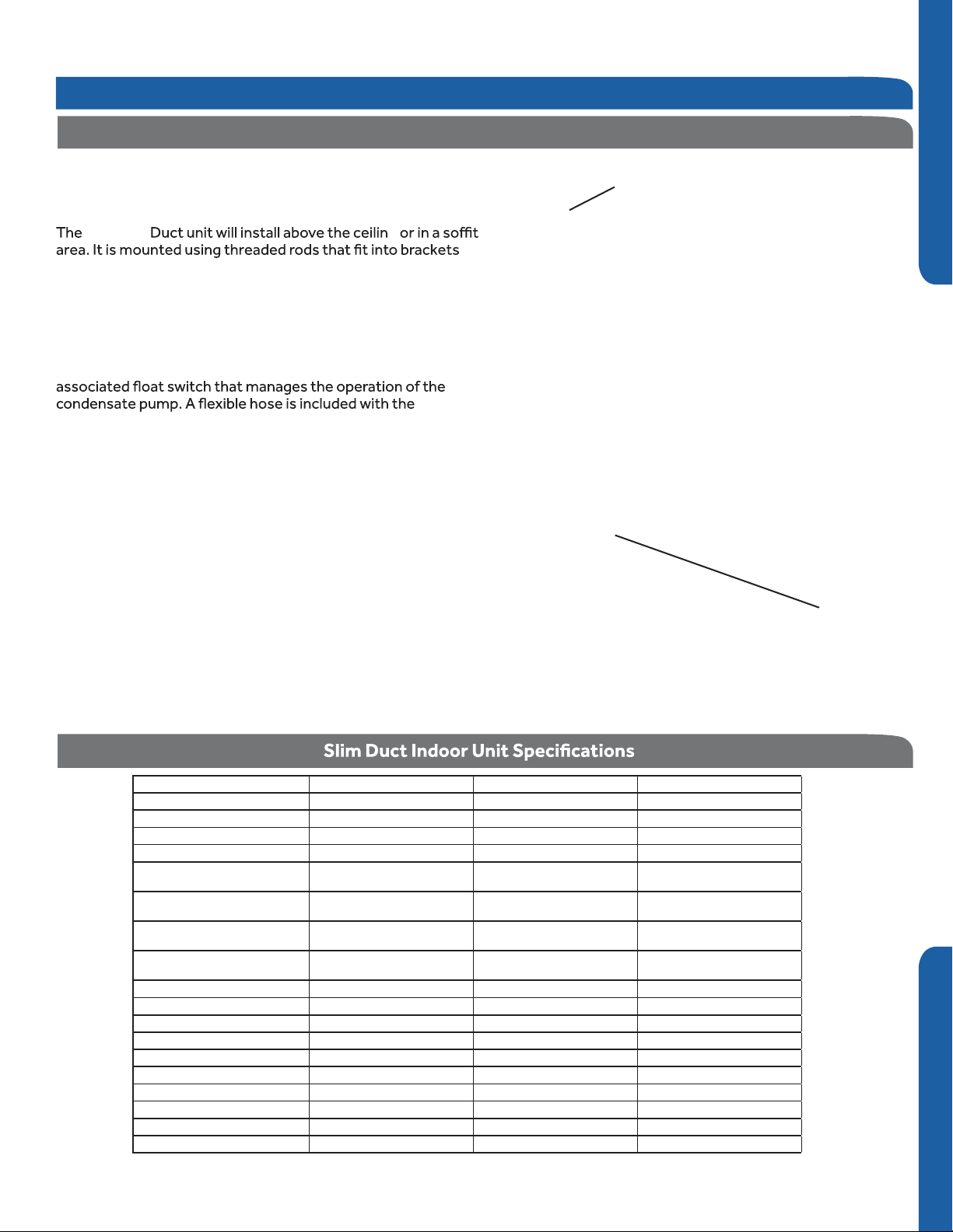
Indoor AM24LP2VHA AM36LP2VHA AM48LP2VHA
Rated Cooling Capacity Btu/hr 24,000 35,000 47,000
Rated Heating Capacity Btu/hr 26,500 37,500 52,000
Voltage, Cycle, Phase V/Hz/-
Fan Speed Stages 4+Auto 4+Auto 4+Auto
Airflow (Turbo/High/
Med/Low/Quiet) CFM
Motor Speed (Turbo/High/
Med/Low/Quiet) RPM
Max. External Static Pressure in.W.G
Indoor Sound Level dB (Turbo/High/
Dimension: Height in (mm)
Dimension: Width in (mm)
Dimension: Depth in (mm)
Weight (Ship/Net)- lbs (kg)
Internal Condensate Pump Standard Standard Standard
Max. Drain-Lift height in(mm)
(Pa)
Med/Low)
Connections Flare Flare Flare
Liquid O.D. in 3/8 3/8 3/8
Suction O.D. in 5/8 5/8 5/8
Drainpipe Size O.D. in 1 1/4 1 1/4 1 1/4
208/230/60/1 208/230/60/1 208/230/60/1
845/670/530/470 1100/950/735/675
950/860/760/700
0.6(150) 0.6(150) 0.6(150)
38/35/32/29 32/28/25/23
9 7/8 (250) 9 7/8 (250) 9 7/8 (250)
37 5/8 (957) 59 (1500) 59 (1500)
25 3/4 (655) 28 3/8 (720) 28 3/8 (720)
81.1/68.8(36.8/31.2) 130.1/121.3 (59/55) 132.3/114.6 (60/52)
27 9/16(700) 27 9/16(700) 27 9/16 (700)
1000/920/860/810 1180/1080/1010/960
1350/1150/930/765
41/36/33/31
INSTALLATION
SECTION D
PAGE 23

Introduction - Ov
r
erview
Condensate Handling
The High ESP Duct unit has a built-in condensate pump and
water level safety switch. There are also two optional ports
for gravity drainage. The condensate pump is rated to lift
water up to 24” from the point of discharge on the High ESP
ENGLISHSECTION D
Duct unit.
The High ESP Duct unit comes with a grey connection hose
with clamp. This hose is connected to the High ESP Duct unit
condensate discharge hose port. The other end of the hose
is sized to accept 3/4 inch PVC piping.
Electrical Power
Follow all local codes and regulations when installing electrical
wiring.
Route required electrical power to area where the High ESP
Duct unit is to be located. Maintain at least a 10 foot
separation between TV and Radio wiring and the power to
the indoor unit.
14 Gauge AWG stranded wire should be used t
electrical connection between indoor and outdoor units.
This wiring will serve to power the indoor unit and establish a
communication link between indoor and outdoor units.
The wiring is connected at the indoor unit electrical terminal
blocks screws 1, 2, 3 and ground. There should be no
splices in the wires connected to terminals 1 or 3 as these
serve as communication signal wires and electrical power
connections. If a safety switch needs to be in place to shut o
power to the indoor unit, break wire 2 only.
o make the
Recommended condensate piping c
here:
12 in. below
3-5 ft.
8.6 in.
ongurations are shown
11 in. unde
8.6 in.
19.6 in. below
Air Delivery Clear
Make certain to maintain proper clearances around the
High ESP Duct unit.
Inadequate clearances can cause sy
temperature control problems.
Service and Maintenance Clearances
Make sure there are adequate clearances for future
maintenance and service. Allow enough room to access the
condensate pump assembly and the electrical control box.
ances
stem freezing and
PAGE 24
INSTALLATION

Step 1 - Preparation
• Drill
• Wire Snipper
• Hole Saw 2 3/4”
• Vacuum pump
• Soap-and-water solution or gas leakage
detector
• Torque wrench
• 17mm, 22mm, 26mm
• Tubing cutter
• Flaring tool
• Razor knife
• Measuring tape
• Level
• Micron gauge
• Nitrogen
• Mini-Split AD-87 Adapter (1/4” to 5/16”)
• A - Non-adhesive Tape
• B - Adhesive Tape
• C - Saddle (L.S.) with screws
• D - Electrical wiring
• E - Drain hose (Included)
• F - Insulation
• G - Piping hole cover (Included)
Procedure for Selecting the LocationRequired Tools for Installation
• Place above the ceiling or in sot area
where you have enough space to position
the unit.
• Place where the drainage pipe can be
properly positioned.
• Place where the inlet and outlet air of the
indoor unit will not be blocked.
• Do not install the unit in a place with
heavy oil or moisture (e.g. - kitchens and
workshops)
• Do not install in a location with
destructive gas (such as sulfuric acid gas)
or pungent gas (thinner and gasoline) are
used or stored.
• Choose a place solid enough to bear the
weight and vibration of the unit and where
the operation noise will not be amplied.
• Install where there are no expensive
items like a television or piano below the
indoor unit.
• Leave enough space for maintenance.
• Install at least 3 ft. away from televisions
and radios to avoid interference.
Threaded Rod Mounting Information
ENGLISH SECTION D
Note:
1) R-410A refrigerant is a safe, nontoxic
and nonammable refrigerant. However,
if there is a concern about a dangerous
level of refrigerant concentration in the
case of refrigerant leakage, add extra
ventilation.
The High ESP Duct unit should be mounted to the
building structure using threaded rods. The threaded
rods should have washers and nuts to allow the height
and level of the High ESP Duct unit to be adjusted.
The threaded rods and attachment brackets are eld supplied
items. The materials required for mounting to the brackets
on the High ESP Duct unit include:
4- 3/8” Threaded Rods
4- Mounting Brackets
Washers
Nuts (Double nut the assembly as shown in step 2.3)
INSTALLATION
PAGE 25

Step 2 - Installation of the High ESP Duct Unit
Step By Step Guide To High ESP Duct Unit Installation
2.1
Step 2.1
ENGLISHSECTION D
Determine and mark the position of where the High ESP
Duct unit is to be installed. Install the hardware necessary
to mount the threaded rods. Always select a location
strong enough to support the indoor High ESP Duct unit.
2.2
Step 2.2
Install the threaded rods to the hardware attached to the
structure.
2.3
Step 2.3
Lift the High ESP Duct unit and position the threaded rods into
the 4 mounting clips, one located on each corner of the unit.
2.4
Step 2.4
Using a level, adjust the nuts on the threaded rods to obtain
level readings both side to side and front to back on the
High ESP Duct unit.
2.5
Step 2.5 - 2.5A
Prior to routing the refrigerant lines to the unit, install the
supplied are nuts onto the refrigerant lines. Using a aring
tool, flare the refrigerant lines. Remove the caps attached
to the ends of the refrigerant line connections at the High
ESP Duct unit. Holding charge should leak out. Attach the
refrigerant lines to the air handler.
Using a torque wrench, torque the ttings to the proper
specications. (See Outdoor Unit Section for are torque
settings.)
Step 2.1
Step 2.2
Step 2.3
2.6
Step 2.6
Connect the grey flexible drain hose supplied with the High
ESP Duct unit to the condensate pump discharge pipe of
the High ESP Duct unit. Tighten the clamp securely. Using
3/4 “ PVC, connect the flexible hose to the building’s
condensate drain system.
2.7
Steps 2.7 - 2.7A - 2.7B
Route the 14AWG stranded 4 conductor power/
communication cable and the wired remote cable to the air
handler. Use reducing washers and appropriate connector
to attach the power/communication cable to the unit. The
wired remote cable will enter the unit through a rubber
grommet. The 4 conductor cable connects to the terminal
block at terminals 1, 2, 3, and ground. The wired remote
cable connects to the air handler main board at connector
CN1. Re-install electrical box cover.
2.8
Step 2.8
The unit is now ready for connection to the ductwork.
The return air duct can be congured as either a rear side
inlet or bottom side inlet.
Step 2.4
PAGE 26
INSTALLATION

Rear side air inlet
Step 2 - Installation of the High ESP Duct Unit
Step 2.5
Step 2.5A
Step 2.7A
Step 2.7B
Re-install electrical box cover
ENGLISH SECTION D
Step 2.6
Step 2.8
Diffuser
Return Duct
Bottom side air inlet
Step 2.7
Diffuser
Return Duct
INSTALLATION
INSTALLATION IS NOW COMPLETE
PAGE 27
Step 3 - Electrical Connections
Outdoor unit
Electrical Connections Indoor and Outdoor Units
14 AWG Stranded Wire Only. (Central Controller Not Used)
Maintain 10 feet of separation between TV and any Radio wiring.
ENGLISHSECTION D
Indoor unit
3wire 14AWG
Control Wiring
Power
Wiring
1
(
N
)
2
(L
)
3
(
C
)
1
(
N
)
2
(
L
)
3
(
C
)
Note: High ESP Duct unit ships with YR-E17 wired controller. See Section E for more information.
Step 4 - Pull Vacuum on System
See Step 3.2 of the outdoor unit installation section for how to pull a vacuum.
Indoor High ESP Duct Unit Installation Complete
PAGE 28
INSTALLATION

Section E - Wired Controller YR-E17
WIRED CONTROL PANEL FUNCTIONS
Features and Interface
Clock; Parameter setting/Inquiry; Malfunction
display
Timer ON/OFF; Sleep function; Parameter
setting/Inquiry; Malfunction display
ROOM/SET temp. and humidity display, each
step is 0.5°C (1°F). For example, if the temp is
25°C (77°F), it will display 25.°C (77°F). Humidity
display function is reserved.
Energy Saving function. This icon will be displayed only when energy saving function is set.
Filter Cleaning
Child Lock
Lock/Central
Motion Sensing (Reserved)
Left/Right Swing. This icon is displayed only
when in swing function
ENGLISH SECTION E
Up/Down Swing. This icon is displayed only when
in swing function
Sleep function. This icon is displayed when setting the
sleep function. Remaining sleeping time is displayed in
the top right corner.
Heat Reclaim Ventilation. This icon is displayed when
setting the heat reclaim ventilation.
Electrical Heating. This icon is displayed when electrical
heating is set on DC wired control.
Intelligent Mode--automatic cycling.
Cooling Mode
Heating Mode
Fan Mode
Dry Mode
User Friendly: Back light; Room temperature display
Functions:
Ventilation; ECO; Filter Cleaning; Error Code display; Child
Lock; Parameter Inquiry; Unit NO. Setting; Static Pressure
Grade Inquiry; Temp. Compensation setting; Forced
Cooling/Heating
Clock; Timer; Sleep Function; Heat Reclaim
INSTALLATION
PAGE 29

A TYPE 1, FOR AL24/36/42/48LP2VHA, AM24LP2VHA
Indoor 1
Wire controller
port
Indoor 2
Wire controller
port
Indoor N
Wire controller
port
Indoor 15
Wire controller
port
control wiring of
Wire controller
TYPE 2, FOR AM36/42/48LP2VHA
Indoor 1
Wire controller
port
Indoor 2
Wire controller
port
Indoor N
Wire controller
port
Indoor 15
Wire controller
port
Indoor16
Wire controller
port
Wire controller
Indoor16
Wire controller
port
(master unit)
(master unit)
The communication wiring is 189ft (4.8 meter) long; if the
actual length is more than it, please distribute wiring
according to below table:
B
Indoor 1
Wire controller
port wire
Wire controller
C
Indoor 1
Wire controller
port wire
Wire controller
Polar wire
Wire controller
control wiring of
Wire controller
Wire controller
There are three methods to connection wire controller and
the indoor units:
A: One wired controller can control max.up to 16 sets of
indoor units, for Flexifit Pro series indoor units, there are two
connection method:
Type 1: for model AL24/36/42/48LP2VHA,AM24LP2VHA,the
wiring connection between wired controller - the master unit
(directly connected to the wired controller), master unit slave unit, slave unit-slave unit should be one to one match of
all three lines.
Type 2: for model AM36/42/48LP2VHA,The wiring connection
between wired controller-the master unit (directly connected
to the wired controller) should be three polar wire, and the
wiring between master unit - slave unit, slave unit-slave unit
should be one to one match of two polar lines.
Note: PCB DIP switches are used for setting slave units, please refer
to indoor unit wiring diagram.
B. One wire controller controls one indoor unit, and the indoor
unit connects with the wire controller through 3 pieces of
polar wire.
C. Two wired controllers control one indoor unit. The wire
controller connected with indoor unit is called master one, the
other is called slave one. Master wire controller and indoor
unit; master and slave wire controllers are all connected
through 3 pieces of polar wire.
Note: There are PCB DIP switches for slave or master units
selection, please refer to the indoor unit wiring diagram to get
details.
*One side of the shielded sheet of communication wire
must be earthed.
Indoor PCB port.
For location
number ,refer
to indoor unit wiring
diagram.
About the wire:
The wire controller is equipped with special communication
wiring in the accessories. 3-core terminal (1-white 2-yellow 3red) is connected with the terminal A, B, C of wire controller
respectively.

WIRED CONTROLLER INSTALLATION
Wired Controller Wiring Instructions
Dimensions
Unit: inch (mm)
ENGLISH
Dip Switch
Dip Switch ON/OFF Function Default Setting
SW1-1
SW1-2
SW1-3
SW1-4
SW1-5
SW1-6
SW1-7
SW1-8
ON Set as the slave controller
OFF Set as the master controller
ON Ambient temp. display available
OFF Ambient temp. display unavailable
ON Display ambient temp. from PCB of indoor
OFF Display ambient Temp. from wired controller
ON Auto-restart invalid
OFF Auto-restart valid
ON Fahrenheit
OFF Celsius
ON Swing angle adjustment available
OFF Swing angle adjustment unavailable
ON Up/Down and Left/Right swing
OFF Up/Down swing
ON Fresh Air unit
OFF General unit
OFF
OFF
OFF
OFF
OFF
OFF
OFF
OFF
REMOTE CONTROLS
PAGE 31

WIRED CONTROLLER OPERATION
Settings & Functions
Initialization
The wired controller will
ENGLISHSECTION E
1
2
3
This cycle keeps repeating until initialization is complete.
The green ON/OFF LED will also ash continuously until
initialization is complete.
If the wired controller is unable to communicate with the
indoor unit PCB after powering on, initialization will terminate
in 4 minutes. The communication malfunction can be checked
using the malfunction inquiry function. (See Malfunction
Display)
momentarily display
all display icons upon
powering up or when
resetting the system.
During the initialization
process, the controller
will display, in a
repeating order:
88:88 (upper left
corner), 88:88 (upper
right corner) 88.8
(main temperature).
Mode Setting
NOTE: This function requires the ON/OFF key LED to be
turned OFF and the screen backlight to be illuminated.
Press and hold the MODE key for 5 seconds, the number of
the mode currently being used will display in the upper left
corner of the screen. (Default is 0) Press the pq keys to
change to one the dierent modes available: 0, 1, 2, or 3.
Press SET to conrm the setting.
NOTE: Corresponding modes
0 – [Intelligent] [Cooling] [Heating] [Fan] [Dry]
1 – [Cooling] [Heating] [Fan] [Dry]
2 – [Cooling] [Fan] [Dry]
3 – [Cooling] [Heating] [Fan] [Dry] (same as 1)
Error Code Display
Note: This function requires the ON/OFF key LED to be
turned OFF and the screen backlight to be illuminated.
Press and hold the TIME key for 10 seconds. The unit number
will display in the upper left corner of the screen. The error
code/historical error code will display in the upper right corner
of the screen. Press pq keys to select the unit number to
view its error codes. Under Error Code display screen, press
and hold the TIME key for 5 seconds to clear the fault codes of
all the units.
Switching between Fahrenheit & Celsius
To switch from Celsius to Fahrenheit, select the mode you
wish to operate (COOL, HEAT, DRY, INTELLIGENT/AUTO).
Press and hold the p key to reach 30 °C then continue holding
the p key for 15 seconds until the display reads 86 °F. Use the
pq keys to adjust to desired temperature.
To switch from Fahrenheit to Celsius, select the mode you
wish to operate (COOL, HEAT, DRY, INTELLIGENT/AUTO).
Press and hold the q key to reach 60 °F then continue holding
the q key for 15 seconds until the display reads 16 °C. Use the
pq keys to adjust to desired temperature.
Clock Function
1. The clock is displayed in 24 Hour time
A. It cannot be set for AM/PM.
B. The clock function cannot be set when SLEEP
function or a timer function is currently set.
When the system is rst powered up, after initialization, the
clock will default to 12:00. Within 10 seconds of the clock being displayed, the time can be set. The clock icon and minutes
portion of the time display will be ashing. Press the pq keys
to adjust the minutes. (Pressing and holding the pq keys will
accelerate the time adjustment.) With the minutes set, press
the TIME key. The clock icon and hours portion of the time
display will now begin ashing. Press the pq keys to adjust
the hours. Press the SET key to conrm the setting.
To set the clock after initial power up or reset time has expired, press and hold the TIME key for 5 seconds. The clock
icon and minutes portion of the time display will begin ashing. Press the pq keys to adjust the minutes. With the min-
utes set, press the TIME key. The clock icon and hours portion
of the time display will now begin ashing. Press the pq keys
to adjust the hours. Press the SET key to conrm the setting.
If neither pq key is pressed within 10 seconds, or if the
MODE, FAN, or ON/OFF keys are pressed prior to pressing the
SET key, the setting function is canceled and the time reverts
back to the previous setting.
Screen Saving
With the system turned o, tap the TIME key to activate the
screen backlight (if not already lit).
1. Press and hold the TIME and q keys for 5 seconds to set the
backlight “on” time. The set time will be displayed in the upper
right corner of the screen.
2. Press the pq keys to adjust the time. Set times available
are: 0 seconds (backlight always on), 15 seconds, 30 seconds,
and 60 seconds. Initial default time is 15 seconds.
3. With time selection made, press the SET key to conrm the
setting.
Press the MODE, FAN, TIME, SET, or ON/OFF key to exit the
function. If no key is pressed in 10 seconds, the function
will also exit. If there are no current errors or historical error
codes, “--” will be displayed.
PAGE 32
INSTALLATION
If neither pq key is pressed within 10 seconds, or if the
MODE, FAN, or ON/OFF keys are pressed prior to pressing the
SET key, the setting function is canceled and reverts back to
the previous setting.
WIRED CONTROLLER OPERATION
Settings & Functions
ECO Energy Saving Function
NOTE: This function requires the ON/OFF key LED to be
turned ON and the screen backlight to be illuminated.
Press the SET key. The swing louver function icon will
ECO
be ashing) Press the SET key to conrm the setting. The ECO
icon will remain on.
To cancel ECO function, repeat the above steps.
NOTE: The energy saving default parameters are listed below:
74°F Lowest temperature limit of Cooling and Dry mode.
78°F Highest temperature limit of Heating mode.
74°F – 86°F Temperature adjustment range in Cooling and Dry
mode.
60°F – 78°F Temperature adjustment range in Heating mode.
be displayed. Press the pq keys to advance through
the functions to select ECO function. (The icon will
ECO Parameter Setting
NOTE: This function requires the ON/OFF key LED to be
turned ON and the screen backlight to be illuminated.
For Cooling
Under Cooling mode, set the temperature to 86°F. Press and
hold the FAN key for 5 seconds. The Cooling ECO param-
eter (ashing) will be displayed in the upper left corner of the
screen. Default temperature is 74°F. Press the pq keys to
adjust the lowest target cooling temperature. Press the SET
key to conrm the setting and exit setup.
For Heating
Under Heating mode, set the temperature to 60°F. Press and
hold the FAN key for 5 seconds. The Heating ECO parameter
(ashing) will be displayed in the upper right corner of the
screen. Default temperature is 78°F. Press the pq keys to
adjust the highest target heating temperature. Press the SET
key to conrm the setting and exit setup.
ENGLISH SECTION E
Timer Function Setting
NOTE: The display backlight must be illuminated before proceeding. To turn the backlight on, press any key (MODE, FAN, pq,
TIME, or SET) located at the bottom of the
display, or press the ON/OFF key located at
the top of the display.
Timer ON
Press the TIMER key once, the ON timer icon will appear in the
upper right corner of the screen. The ON icon and hour position are ashing. Press the pq keys to set the hour. Press
the TIMER key again, the ON icon and minutes position are
now ashing. Press the pq keys to set the minutes. Press the
SET key to conrm the setting.
Timer OFF
Press the TIMER key 3 times, the OFF timer icon will appear in
the upper right corner of the screen. The OFF icon and hour
position are ashing. Press the pq keys to set the hour.
Press the TIMER key again, the OFF icon and minutes position
are now ashing. Press the pq keys to set the minutes. Press
the SET key to conrm the setting.
Timer ON/OFF
Press the TIMER key 5 times, the ON/OFF timer icon will appear in the upper right corner of the screen. The ON icon and
hour position are ashing. Press the pq keys to set the hour.
Press the TIMER key again, the ON icon and minutes position
are now ashing. Press the pq keys to set the minutes. Press
the TIMER key again, the OFF icon and hour position are now
ashing. Press the pq keys to set the hour. Press the TIMER
key again, the OFF icon and minutes position are now ashing.
Press the pq keys to set the minutes. Press the SET key to
conrm the setting. Based on the times set, the indoor unit
will determine which event happens rst (ON-OFF or OFFON) and adjusts the arrow direction accordingly.
Static Pressure Grade Inquiry & Adjustment
NOTE: This function requires the ON/OFF key LED to be
turned ON and the screen backlight to be illuminated.
Press and hold the SET and FAN keys for 5 seconds. The current static pressure will be displayed in the upper right corner
of the screen and the “Static Pressure” icon will begin to ash.
Press the TIME key to shift the unit no. displayed in the upper
left corner of the screen. The unit numbers are from 00-15.
Press the pq keys to change the static pressure grade,
shown in the upper right corner of the screen.
Number range is 01-04. Press the SET key to conrm the
setting. Press the MODE, FAN, or ON/OFF key to exit the
function. If no key is pressed in 10 seconds, the function will
also exit.
INSTALLATION
If neither pq key is pressed within 10 seconds, or if the
MODE, FAN, or ON/OFF keys are pressed prior to pressing the
SET key, the setting function is canceled and reverts back to
the previous setting.
Timer Cancel
Press the TIME key up to 9 times to cycle through the timer
settings. When the timer icon disappears, the timer function is
canceled.
Note: An active timer function will remain displayed on screen
until the set time has been reached and command completed.
PAGE 33

WIRED CONTROLLER OPERATION
Settings & Functions
Left/Right/Up/Down Swing
The swing function deter-
ENGLISHSECTION E
mines air circulation.
1. Press SET key to access
Swing function circulation.
2. Use pqkeys to select
desired swing function.
If SW7 is on, air will circulate
UP/DOWN/LEFT/RIGHT.
3. Press SET key to conrm
swing function selection.
Parameter Inquiry
NOTE: This function requires the screen backlight to be illuminated. The ON/OFF key LED can be either On or O.
Press and hold the SET key for 5 seconds. The unit number
will be displayed in the upper left corner of the screen. The
data type and current data will be displayed in the upper right
corner of the screen.
Press the pq keys to scroll through the data types. (See
chart for data type/current data)
Press the MODE, FAN, SET, or ON/OFF key to exit the function. If no key is pressed in 10 seconds, the function will also
exit.
Forced Cooling/Heating
Note: This function requires the ON/OFF key LED to be
turned OFF and the screen backlight to be illuminated.
Forced Cooling
When the system is turned o in cooling mode, press and hold
the ON/OFF key for 10 seconds. The system will enter forced
cooling. The temperature display will display a ashing “LL”.
Press the ON/OFF key to exit forced cooling mode.
Forced Heating
When the system is turned o in heating mode, press and hold
the ON/OFF key for 10 seconds. The system will enter forced
heating. The temperature display will display a ashing “HH”.
Press the ON/OFF key to exit forced heating mode.
NOTE: When in forced cooling or heating, all keys are disabled
except for the ON/OFF key.
Child Lock Function
NOTE: This function requires the screen backlight to be illuminated. The ON/OFF key LED can
be either On or O.
Child Lock can be used to prevent unintended
operation of the control unit.
1. Press SET and the q keys together for 5 seconds to
activate the Child Lock function. The child lock icon will be
displayed on the left side of the screen. All normal functions of
the keys will be disabled.
Unit Number Setting
NOTE: This function requires the screen backlight to be il-
luminated. The ON/OFF key LED can be either On or O.
Press and hold the SET key for 10 seconds. The wired controller address and communication address between the indoor
and outdoor unit are displayed in the upper left corner of the
screen. The central address is displayed in the upper right
corner of the screen.
Press the pq keys to select the indoor unit number: 0 - 3F.
Press the SET key to conrm the setting. Press the MODE,
FAN, or ON/OFF key to exit the function. If no key is pressed in
10 seconds, the function will also exit.
PAGE 34
INSTALLATION
2. To unlock the Child Lock function, press the SET key and
the q arrow together for 5 seconds. The child lock icon will
disappear from the screen. All normal functions of the keys
will be restored.
Temperature Compensation Setting
Note: This function requires the ON/OFF key LED to be
turned OFF and the screen backlight to be illuminated.
Press and hold the FAN keys for 5 seconds, the current
temperature compensation value is displayed in the upper
right corner of the screen. (The default value is 00). Press the
pq keys to change the temperature compensation value.
The adjustment range is -07°F to +07°F. Press the SET key to
conrm the setting. Press the MODE, FAN, TIME, or ON/OFF
key to exit the function. If no key is pressed in 10 seconds, the
function will also exit.
NOTE: The compensation value is used for ambient temperature and is valid only for the wired controller sensor.

WIRED CONTROLLER OPERATION
Settings & Functions
Sleep Function
NOTE: This function requires the ON/OFF key LED to be
turned ON and the screen backlight to be illuminated.
Press the SET key. The swing louver function icon
will be displayed. Press the pq keys to advance
through the functions to select the SLEEP func-
tion. The Sleep and Sleep “o” time icons will be
displayed. (The Sleep icon will be ashing) Press the TIME key,
the “o” icon will begin to ash. Press the pq keys to set the
“o” time. (Time range is 0.5h to 72h) Press the SET key to
conrm the setting. The Sleep function and “o ” time icons
will remain on.
If neither pq key is pressed within 10 seconds, or if the
MODE, FAN, or ON/OFF keys are pressed prior to pressing the
SET key, the setting function is canceled and reverts back to
the previous setting.
To cancel the Sleep function. Press the SET key. The swing
louver function icon will be displayed. Press the pq keys to
advance through the functions to select the SLEEP function.
The Sleep and Sleep “o” time icons will be displayed. (The
Sleep icon will be ashing) Press the SET key to cancel the
function.
Filter Cleaning
NOTE: This function requires the ON/OFF key LED to be
turned ON and the screen backlight to be illuminated.
ENGLISH SECTION E
Other Functions
Note: These functions require the ON/OFF key LED to be
turned OFF and the screen backlight to be illuminated.
Auto Restart
Setting DIP switch SW1-4 located on the PCB of the wired
control to the “on” position will disable the auto restart function. When the switch is in the “o” position, auto-restart is
enabled (default position). When the switch is in the “on” posi-
tion, auto-restart is disabled.
Information retained in auto-restart are: Mode, Fan Speed,
Temperature Setting, Swing State, and Heat Reclaim Ventilation function.
Communication Error of Wired Controller
If there is no communication between the wired controller and
indoor unit for 4 minutes, when checking error codes, “07” will
be displayed in the upper right corner of the display.
The Filter Cleaning icon will start ashing when
the indoor unit has reached 500 hours of operating time.
After cleaning or replacing the lter, press the SET key to clear
the icon and reset the operating time.
Heat Reclaim Ventilation
NOTE: This function requires the ON/OFF key LED to be
turned ON and the screen backlight to be illuminated.
Press the SET key. The swing louver function icon
will be displayed. Press the pq keys to advance
through the functions to select the Heat Reclaim
Ventilation function. (The icon will be ashing)
Press the SET key to conrm the setting.
To cancel the Heat Reclaim Ventilation function, repeat the
above steps.
If neither pq key is pressed within 10 seconds, or if the
MODE, FAN, or ON/OFF keys are pressed prior to pressing the
SET key, the setting function is canceled and reverts back to
the previous setting.
This function is reserved for future models.
INSTALLATION
PAGE 35

[This page intentionally left blank.]

Display
Section F - Wireless Remote Controller
7
2
3
4
11
15
13
17
18
Functions
1
5
6
109
8
12
14
16
19
Note:
TURBO/QUIET modes are only available when the unit is under cooling or heating mode (not for auto or fan mode).
Running the unit in QUIET mode for a long period of time
may cause the room temperature to not reach the set
temperature. If this occurs, cancel QUIET mode and set the
fan speed to a higher setting.
3
COOL Button
In COOL mode, the unit operates in cooling. When FAN is
set to AUTO, the air conditioner automatically adjusts the
fan speed according to room temperature. The
displayed during COOL mode.
4
HEAT Button
In HEAT mode, warm air will blow out after a short period of
the time due to cold-air prevention function. When FAN is
set to AUTO, the air conditioner automatically adjusts the
fan speed according to room temperature. The
displayed during HEAT mode.
5
DRY Button
DRY mode is used to reduce humidity. In DRY mode, when
room temperature becomes lower than temp. setting +2°F,
unit will run intermittently at LOW speed regardless of FAN
setting. The
6
Temperature +/- Buttons
Temp + Every time the button is pressed, the temperature
setting increases.
Temp - Every time the button is pressed, temperature
setting decreases.
The operating temperature range is 60°F-86°F.
will be displayed during DRY mode.
will be
will be
ENGLISH SECTION A
1
Power Button
Press the ON/OFF button on the remote control to start
the unit.
2
TURBO/QUIET Button
The TURBO function is used for fast heating or cooling.
Press the TURBO/QUIET
control will display the TURBO
side of the remote display and switch the unit to the TURBO
function.
The QUIET function may be used when silence is needed for
fast rest or reading. Press the TURBO/QUIET
again to switch to QUIET mode and the remote control will
display the QUIET
remote display.
Press the TURBO/QUIET
TURBO/QUIET and return to normal operation.
icon on the bottom left side of the
button once and the remote
icon on the bottom right
button
button a third time to cancel
INSTALLATION
7
AUTO Button
Under the mode of auto operation, the air conditioner will
automatically select Cool, Heat, or Fan operation according
to set temperature. When FAN is set to AUTO the air condi-
tioner automatically adjusts the fan speed according to room
temperature. The
8
FAN Button
Fan speed selection
Press the FAN
as follows:
Remote control:
MED HI
LOW
The air conditioner fan will run according to the displayed fan
speed.
When FAN is set to AUTO, the air conditioner automatically
adjusts the fan speed according to room temperature.
will be displayed during AUTO mode.
button. For each press, fan speed changes
circulated
AUTO
PAGE 37

WIRELESS REMOTE CONTROLLER OPERATION
9
Louver SWING Button - Vertical
Air Flow Direction Adjustment
Press the SWING UP/DOWN button to choose the position of
the vertical airow louvers.
ENGLISHSECTION A
Status display of air ow
COOL/DRY:
HEAT:
Caution:
• It is advisable not to keep the vertical louver in the down-
ward position for an extended period of time in COOL or
DRY mode, otherwise condensate water may form on the
louver.
•
Note:
When turning the unit on, the remote control will automatically
return the louver to the previous set swing position. When turn-
ing the unit o, the louver will rotate to the full open position
prior to closing.
10
Louver SWING Button - Horizontal
Press the SWING UP/DOWN button to choose the position of
the horizontal airow louvers.
4. Once the desired length of time is selected for the unit to
turn on, press the CONFIRM/CANCEL
to conrm
this setting.
The remote control display changes as follows:
0.5h
TIMER ON TIMER OFF TIMER ON-OFF
0.5h 0.5h
0.5h
TIMER OFF-ON
BLANK
Cancel TIMER ON setting:
With a TIMER ON set, press the CONFIRM/CANCEL
button once to cancel the TIMER ON.
Turning the unit ON with the TIMER from it being OFF will look
like this on the remote control display:
Note:
Holding the TIMER ON
button down will rapidly cycle
the time. After replacing batteries or a power failure occurs,
the time setting will need to be reset.
According to the Time setting sequence of TIMER ON or
TIMER OFF, either Start-Stop or Stop-Start can be achieved.
Status display of air ow
COOL/DRY/HEAT:
'
Caution:
• When humidity levels are high, condensate water may oc-
cur at the air outlet if all horizontal louvers are adjusted to
left or right.
Note:
When turning the unit on, the remote control will automatically
return the louver to the previous set swing position. When turn-
ing the unit o, the louver will rotate to the full open position
prior to closing.
11
Timer ON Button
On-O Operation
1. Start the unit and select the desired operating mode.
2. Press the TIMER ON
button to enter the TIMER ON
mode. The remote control will start ashing “ON”.
3. Every time the TIMER ON button is pressed the length of
time increases in 0.5 hour increments between hours 0 and
12, and 1 hour increments for times between hours 12 and
24.
12
Timer OFF Button
On-O Operation
1. Start the unit and select the desired operating mode.
2. Press the TIMER OFF
button to enter the TIMER OFF
mode. The remote control will start ashing “OFF”.
3. Every time the TIMER OFF button is pressed the length of
time decreases in 0.5 hour increments between hours 0
and 12, and 1 hour increments for times between hours 12
and 24.
4. Once the desired length of time is selected for the unit to
turn o, press the CONFIRM/CANCEL
to conrm
this setting.
The remote control display changes as follows:
0.5h
TIMER ON TIMER OFF TIMER ON-OFF
0.5h 0.5h
0.5h
TIMER OFF-ON
BLANK
Cancel TIMER OFF setting:
With a TIMER OFF set, press the CONFIRM/CANCEL
button once to cancel the TIMER OFF.
Turning the unit OFF with the TIMER from it being ON will look
like this on the remote control display:
Note:
Holding the TIMER OFF
button down will rapidly cycle
PAGE 38
INSTALLATION

Healthy
Healthy
WIRELESS REMOTE CONTROLLER OPERATION
the time. After replacing batteries or a power failure occurs,
the time setting will need to be reset.
According to the Time setting sequence of TIMER ON or
TIMER OFF, either Start-Stop or Stop-Start can be achieved.
13
SLEEP Button
Sleep mode
Press the Extra Function
options, cycle the button to display the
icon will ash. Press the Conrm/Cancel
button to enter additional
icon, the
button to
enter the sleep function.
Sleep Operation Mode
1. SLEEP mode during COOL, DRY modes
One hour after SLEEP mode starts, the temperature will
rise 2°F above set temperature, after another hour, the
temperature rises an additional 2°F. The unit will run for an
additional six hours, then turns o. The nal temperature
is 4°F higher than the initial set temperature. Using this
feature will help with achieving maximum eciency and
comfort from your unit while you sleep.
SLEEP operation starts SLEEP operation stops
1 hr
Temp.setting
Approx.6hrs
O
F
Rises 2
1 hr
O
Rises 2
F
In COOL, DRY mode
Unit stop
2. SLEEP mode during HEAT mode
One hour after SLEEP mode starts, the temperature will
decrease 4°F below set temperature, after another hour,
the temperature will decrease an additional 4°F. After an
additional three hours, the temperature will rise by 2°F.
The unit will run for an additional three hours, then turns
o. The nal temperature is 6°F lower than the initial set
temperature. Using this feature will help with achieving
maximum eciency and comfort from your unit while you
sleep.
Temp.setting
1 hr
SLEEP
operation starts
Decreases 4OF
1 hr
Decreases 4
3 hrs
In HEAT mode
Unit stop
O
F
3 hrs
Rises 3OF
SLEEP
operation stops
3. In AUTO mode
The unit operates in corresponding sleep mode adapted
to the automatically selected operation mode.
Note:
-When the unit is set to sleep mode, the fan speed will be
set to low speed and cannot be changed.
-When the TIMER function is set, the sleeping function
cannot be set. If the sleeping function has been set, and
the user sets the TIMER function, the sleeping function
will be canceled, and the unit will be set to the timer
function.
14
EXTRA FUNCTION Button
Function:
A) Refresh air - Feature not available on this series.
B) A-B Yard - This will allow you to control two separate units
with a single remote control.
Note: this feature would be setup at the time of installation
by the contractor.
C) Fan Mode - Is indicated by the
icon. Only the fan will
operate in this mode. See section 8 “FAN Button” for
changing the fan settings.
D) Intelligent upward airow, E) Intelligent downward airow,
F) Reset intelligent airow position
1. Press the ON/OFF button on the remote control to turn
the unit on.
Select the desired operating mode.
2. Setting the intelligent airow function
Press the EXTRA FUNCTION
button to enter additional options. Press this button repeatedly to access
the louver settings. The louver icon will cycle through the
following three settings.
airflow
upward
airflow
downward
Present
position
Select the desired position, then press the CONFIRM/
CANCEL
button to set the function.
3. Canceling the intelligent airow function
Press the EXTRA FUNCTION
button to enter additional options. Press this button repeatedly to access the
louver settings. Cycle the button to the louver icon “present” position, then press the CONFIRM/CANCEL
button to cancel the function.
Notice: Do not reposition the horizontal louver by hand.
This may cause the louver to run incorrectly and not
match the icon displayed on the remote control. If the
louver is not running correctly, turn the unit o for one
minute, then back on, and adjust the louver setting with
the remote control.
Note:
1. After setting the intelligent airow function, the louver
position is xed.
2. In cooling, it is better to select the
3. In heating, it is better to select the
mode.
mode.
4. In cooling and dry modes, using the air conditioner for a
long period of time under high humidity conditions, condensate water may form on the grille/louver.
ENGLISH SECTION A
INSTALLATION
PAGE 39

WIRELESS REMOTE CONTROLLER OPERATION
G) Fahrenheit/Celsius mode shift on unit and remote -
To switch between Fahrenheit and Celsius press the EXTRA
FUNCTION
is displayed. Press the CONFIRM/CANCEL
apply the change.
button until either Celsius or Fahrenheit
button to
ENGLISHSECTION A
H) 50°F low temperature heating - Feature not available on
this series.
I) Electrical heating - Feature not available on this series.
15
HEALTH Button
Feature not available on this series.
16
Conrm/Cancel Button
Function: Setting and canceling timer and other functions.
17
LOCK Button
Used to lock buttons and LCD display
18
LIGHT Button
Turns indoor unit display on and o
19
RESET Button
If the remote control is not functioning properly, use a pen
point or similar object to depress this button to reset the
remote.
PAGE 40
INSTALLATION

[This page intentionally left blank.]

www.Haier.com
Model #: 1U24LP2VHA, 1U36LP2VHA,
1U48LP2VHA, AM24LP2VHA, AM36LP2VHA,
AM48LP2VHA, AL24LP2VHA, AL36LP2VHA,
AL48LP2VHA,AW24LP2VHA,AW36LP2VHA
Issued Date: Jan 2017
Haier America,
Wayne, NJ 07470
©2017 Haier America Trading, LLC.
 Loading...