

Haier AV22NMVERA, AV24NMVERA, AV26NMVERA, AV28NMVERA, AV30NMVERA Installation Manual
...
./0 --
Ftf <::B
Nmrs`kk`shnm R`mt`k
W>;:F MJFY UZRU ?:M_
X^OX7::>7:BWJ[8:
F[:BSR[JWF
F[;:SR[JWF
F[;<SR[JWF
F[;>SR[JWF
F[;@SR[JWF
F[;BSR[JWF
F[<:SR[JWF
F[<<SR[JWF
F[<>SR[JWF
F[<@SR[JWF
F[<BSR[JWF
F[<BSR[JWF
F[=:SR[JWF
F[=<SR[JWF
F[=>SR[JWF
F[=@SR[JWF
F[=BSR[JWF
F[>:SR[JWF
F[><SR[JWF
F[>>SR[JWF
F[>@SR[JWF
F[>BSR[JWF

HSRXJRXW
[arning on refrigerant leakage
Wafety caution
Rew environmentally friendly refrigerant V;87F
85 WJPJHX NRWXFPPFXNSR TPFHJ
Hombination of outdoor units
Jquipment series
95 WFKJX] RSXJW
:5 HMJHO TSNRXW
;5 OJ] TSNRXW KSV NRWXFPPFXNSR
<5 VJKVNLJVFRX TNTJ NRWXFPPFXNSR
<58 [ork procedure
<59 Xhree principles of refrigerant pipes
<5: Honfirm refrigerant pipe
<5; Jquipment pipe length of bend pipe and branch pipe
<5< Granch pipe
<5= Lather pipe
<5> Tipe specifications and connection methods
<5? Tipe installation
<5@ Peakage testing
<587 Jvacuation
<588 Vefrigerant charging and additional charging
<589 Hheck valve operation
<58: Vequestment of copper pipe specs and thickness
<58; Xrial running
=5 NRISSV YRNX NRWXFPPFXNSR
=58 Gefore installation
=59 Wtandard accessories
=5: ;4way cassette unit installation
=5; Heiling concealed unit installation
=5< Qed static pressure duct unit installation
=5= Migh static pressure duct unit installation
=5> Honvertible unit installation
=5? [all mounted unit installation
=5@ Honsole unit installation
>5 SYXISSV YRNX NRWXFPPFXNSR
?5 JPJHXVNH [NVNRL
85 Tower wiring figure
95 Hommunication wiring figure
:5 Wpecs for power cable and communication wire
;5 Kield wiring
<5 [iring connection among units
=5 [iring of indoor and outdoor
>5 Jlectric characteristic
?5 Nnstallation instruction of central controller
@5 Honnecting method of central controller and connecting board
/iLY7;0
875 Iip switch setting when out of factory
@5 XVNFP STJVFXNSR
7:
7<
7>
7?
7@
87
8;
8<
8=
8>
8>
8>
8?
8@
8@
9?
9@
:8
:9
::
:;
:;
:<
:<
:=
:=
:=
;7
;@
<:
=8
=?
?=
@:
@?
87<
87=
87=
87>
87@
889
88:
88;
88<
88=
89:
89;
7:
[arnings on refrigerant leakage
Wdeqhfdq`ms cdmrhsx khlhs
Xhe room where the air conditioner is to be installed should be designed or chosen to meet the
standard in case of the refrigerant leakage3 which will ensure the refrigerant will not exceed the limit5
Xhe refrigerant V;87F in the air conditioner product is relatively safe without the poison and the
combustibility5 V;87F is environmentally friendly and is not restricted by the current or pending laws
regarding the protection of the ozone layer5
Visk of suffocation by the leakage of V;87F is minimal5 Mowever3 with the recent increase in the
number of high density buildings and use of multi air conditioner system to ensure effective use of
floor space3 energy conservation and individual control3 installers should ensure it is not possible
to exceed density limits in the event of a refrigerant leak5 Nn particular3 where a single unit of the
multi conditioner system is to be installed into a small room3 select a suitable model and installation
procedure so that if refrigerant leaks out3 density limits are adjacent rooms3 or install mechanical
ventilation combined with a gas leak detection device5
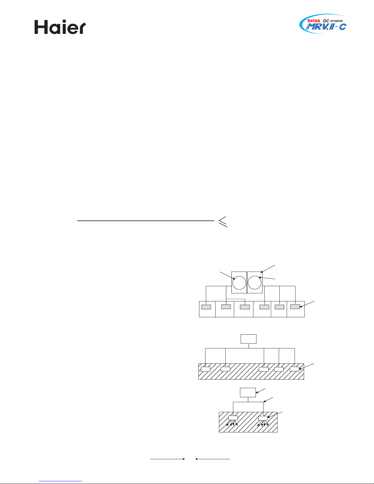
Xhe density can be calculated as shown belowA
Xotal amount of refrigerant /kg0
Qin5 volume of the room where indoor installed
density limit /kg6m
:
0
Xhe density calculation must be in accordance with GW JR :>?5
[hen installing the unit3 please take the above into consideration according to the local laws3 regulation5
Rote 8A Nf there are 9 or more refrigerant
systems in a single area3 the refrigerant amount
should be considered as the individual outdoor5
Kor exampleA
Kor the possible leaking refrigerant in room F3
G and H is 87kg5
Kor the possible leaking refrigerant in room I3
J and K is 89kg5
Rote 9A Xhe standards for minimum room
volume are as followsA
/80 Ro partition /shaded portion0
/90 [hen there is an effective opening with
the adjacent room for ventilation of leaking
refrigerant gas /opening without a door3 or an
opening 758<- or larger than the respective
floor spaces at the top or bottom of the door05
Voom F
Voom G Voom H Voom I Voom J Voom K
indoor unit
outdoor unit
e5g5 charged amount /89kg0
e5g5 charged amount /87kg0
indoor unit
indoor unit
outdoor unit
refrigerant pipe
7;
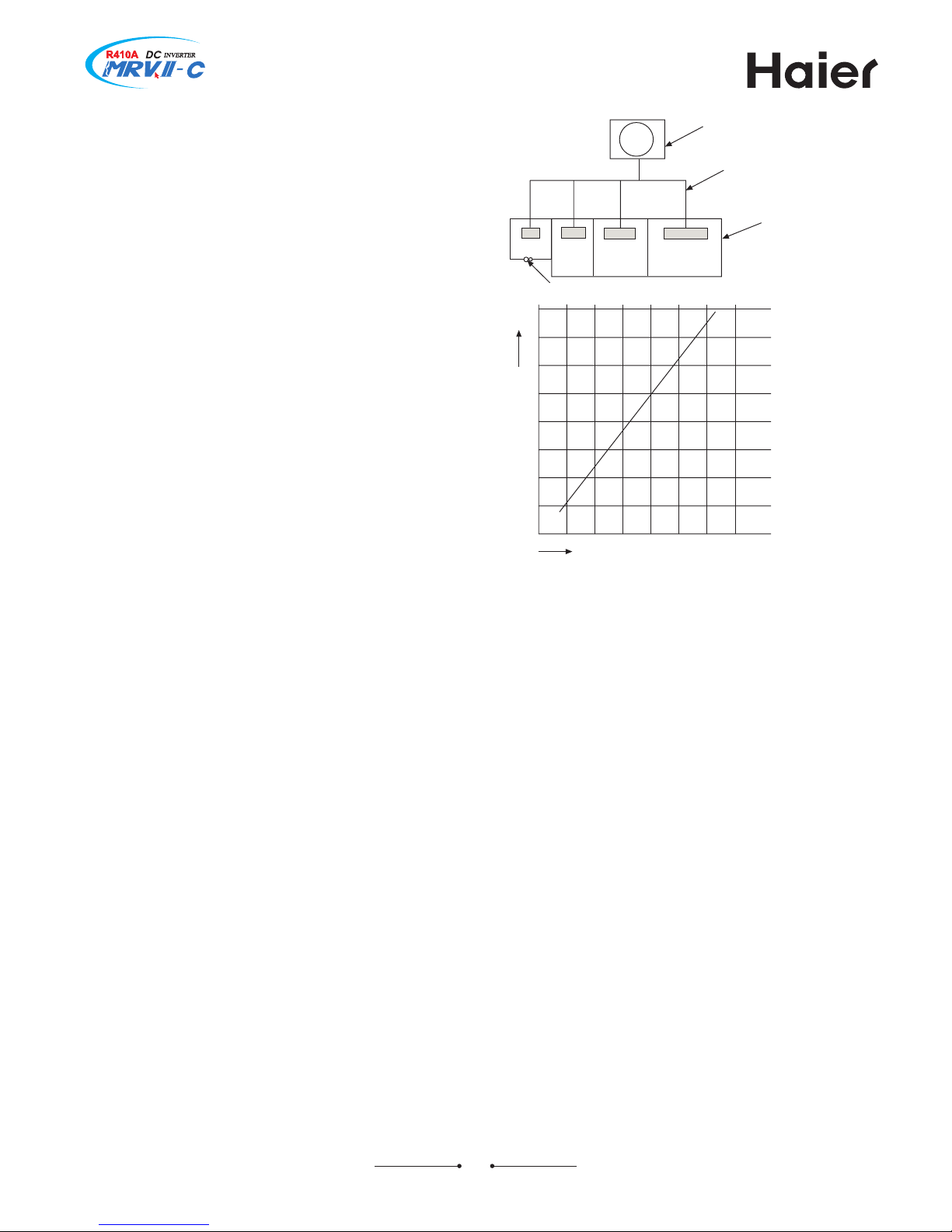
/:0 Nf an indoor unit is installed in each
partitioned room and the refrigerant piping is
interconnected3 attention must be paid to
ensure safeguards are in place to avoid density
limits being exceeded in each partitioned area5
[hen leak detection is interlocked with
mechanical ventilation equipment is installed
in the smallest room where the density limit
is exceeded3 the volume of the next smallest
room becomes the object5
Rote :A Xhe minimum indoor floor area
compared with the amount of refrigerant is
roughly as follows/when the ceiling height is
95>m05
small
room
large room
indoor unit
outdoor unit
refrigerant pipe
medium
room
smallest
room
gas leakage detector
total refrigerant amount
min5 indoor floor area /m
9
0
7
<
87 8< 97 9< :7 :<
;7
87 97 :7 kg
7<
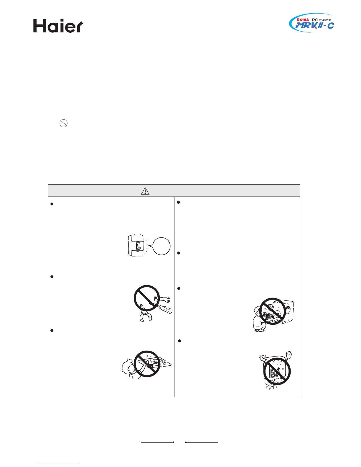
[FVRNRL
Ne `mx `amnql`k ogdmnldm` `qd entmc 4d8f8
rldkk ne ehqhmf56okd`rd bts nee sgd onvdq rtookx
hlldch`sdkx6 `mc bnms`bs sgd cd`kdq sn ehmc nts{
sgd g`mckhmf ldsgnc8
\gdm mddc l`hmsdm`mbd `mc
qdo`hq6b`kk cd`kdq sn g`mckd hs8
Inm{s ots ehftqdr nq `mx nsgdq
sghmfr hmsn sgd hmkds9ntskds `mc
rvhmf kntudq vghkd sgd bnmchsh7
nmdq hr hm nodq`shnm
H`kk sgd cd`kdq sn s`jd ld`rtqdr sn oqdudms sgd
qdeqhfdq`ms eqnl kd`jhmf8
Wwitch
off
Nn such case3to continue using
the air conditioner will damage
the conditioner3and may cause
electrical shock or fire hazard5
Nncorrect maintenance and
repair may cause water leak3
electrical shock and fire hazard5
Gecause the high4speed fan
is very dangerous and may
cause injures5
Xhe leaked refrigerant over certain density may
cause oxygen deficient5Nf the air conditioner is
installed in a small room be sure to take measure
in order to prevent suffocation accident even in
case of refrigerant leakage
\gdm `hq bnmchshnmdq hr qdlnudc `mc qdhmrs`kkdc
cd`kdq rgntkc ad qdronmrhakd enq sgdl8
Nncorrect installation may cause water leaking3
electrical shock and fire hazard5
Inm{s chrl`mskd sgd ntskds ne sgd ntscnnq tmhs8
Xhe exposure of fan is very
dangerous witch may harm
human beings5
Fesdq ` knmf shld trd ne `hq bnmchshnmdq sgd a`rd
rgntkc ad bgdbjdc enq `mx c`l`fdr8
Nf the damaged base is not
repaired3 the unit may fall
down and cause accidents5
WFKJX] HFYXNSR
Nmportant safety information is displayed in this manual5 Tlease pay attention to these points and
keep them in the future carefully5
Jwok`m`shnm ne sgd hmchb`shnmr
Nncorrect operations may result in severe consequences of death or serious injures5
[FVRNRLA
Nncorrect operations may result in injures or machine damagesB in some cases may
cause serious consequences5
HFYXNSR A
A Nt must be strictly prohibited where marked with } Trohibited ~3 otherwise may result in
machine damages or endanger the users| personal safety5
Xhis information can ensure the correct operation of the machine5
NRWXVYHXNSRA
Ge sure to conform with the following important Wafety Hautions5
Xhe Wafety Hautions should be at hand so that they can be checked at any time when needed5
Nf the air conditoner is transferred to the new user3 this manual should be as well transferred to the new user5
7=
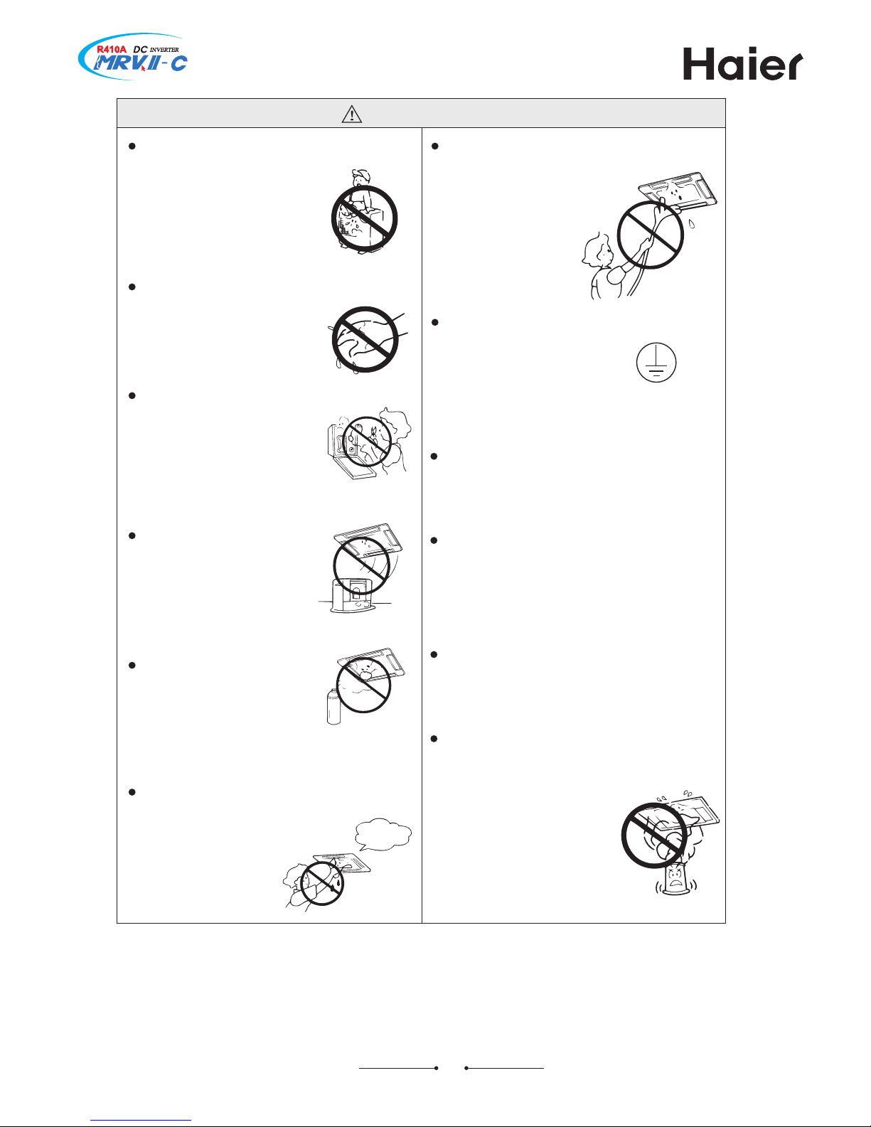
[FVRNRL
Sn fnncr nq mnancx hr odqlhssdc
sn ad ok`bdc nm nq rs`mc nm
ntscnnq tmhs8
Inm{s bkd`m `hq bnmchshnmdq
vhsg v`sdq8
Xhe falling of goods and
people may cause accidents5
Inm3s nodq`sd sgd `hq bnmchshnmdq vhsg
c`lo g`mcr8
Stherwise will be shocked5
Tmkx trd bnqqdbs sxod etrd8
Qay not use wire or any other
materials replacing fuse3othe4
rwise may cause faults or fire
accidents5
Inm{s ok`bd `mx atqmhmf
tmhs hm sgd `hqeknv ne `hq
bnmchshnmdq6vghbg l`x
b`trd hmbnlokdsd
bnlatrshnm
Sn hmek`ll`akd roq`x ekthc
rgntkc ad odqlhssdc sn ad
ok`bdc nq trdc md`q sn `hq
bnmchshnmdq6nsgdqvhrd l`x
b`trd ehqd `bbhcdms8
Fhq bnmchshnmdq rgntkc ad
bkd`mdc nmkx `esdq onvdq
rtookx hr bts nee sn jddo
eqnl rgnbj nq gtqs8
Stherwise may cause shock5
Hnmmdbs d`qsghmf vhqd8
Jarthing wire should not be
connected to the gas pipe3
water pipe3lightning rod or
phone line3incorrect earthing
may cause shock5
Zrd chrbg`qfd ohod bnqqdbskx sn
dmrtqd deehbhdms chrbg`qfd8
Nn correct pipe usage may cause water
leaking5
Fhq bnmchshnmdq b`m{s ad ad hmrs`kkdc hm
sgd dmuhqnmldms vhsg hmek`ll`akd f`rdr8
Xhe inflammable gases near to air conditioner
may cause fire hazard5
Nmrs`kkdc dkdbsqhb`k7kd`jhmf bhqbths aqd`jdq8
\gdm trd sgd etlhf`shmf hmrdbshbhcd
cnm{s nodq`sd `hq bnmchshnmdq8
Stherwise the poisonous chemicals
may settle in air conditioner3
which harm the health of
chemical4allergic people5
Nt easily causes electrical shock without
circuit breaker5
Rot permitted
when running

7>
Sdv dmuhqnmldms`kkx eqhdmckx qdeqhfdq`ms W>;:F
Nmportant safety information is displayed in this manual5 Tlease pay attention to these points and
keep them in the future carefully5
85 Wafety caution concerned with new refrigerant
Xhe pressure of refrigerant V;87F is 85= times than that of refrigerant V995 Xhe refrigerant oil has
also been changed5 Xherefore be sure that the former refrigerant oil and other contaminants are
not mixed into the refrigerating cycle of the air conditioner with the new refrigerant during installation
or service work5 Nf incorrect work is performed3 there is a possibility of serious accident5 Yse tools
and materials exclusive to V;87F5
95 Hautions on installation6service
C Ion.t mix other refrigerants or other refrigerant oil with V;87F5
C Xhe types of tools and joins3 including the service port differ from those of the former refrigerant
in order to prevent mixtakes5
C Xhe operation pressure of V;87F is high3 always use pipes with the correct wall thickness and
which are specified for V;87F5
C Iuring installation3 ensure pipes are clean and ensure contaminants do not enter the pipes because
the system will be affected by the impuries such as the water3 the dirt3 oil3 and so on5
C Jnsure brazing is completed using the nitrogen5
C Yse a vacuum pump for air purge5
C V;87F refrigerant is an azeotropic mixture type refrigerant5 Xherefore use liquid state to charge
the refrigerant5 Nf gas state refrigerant is used3 the composition of refrigerant will change which affects
the performance characteristics of the air conditioner5
:5 Qaterials
C Kor the refrigerant pipes3 use copper pipes and keep the number of joints to a minimum5
C [hen using long copper pipe for V;87F3 it is recommended to use the seamless copper material
which includes bonded oil3 of amount ;7mg687ml or less5
C Io not use crushed3 deformed or discoloured pipes5
C Yse material in which the amount of contaminates inside the pipes or joint are kept to an absolute
minimum5
C Xhe use of flared joint for joining refrigeration pipes should not be used3 except where fitted to
the indoor6outdoor units by the factory5
7?
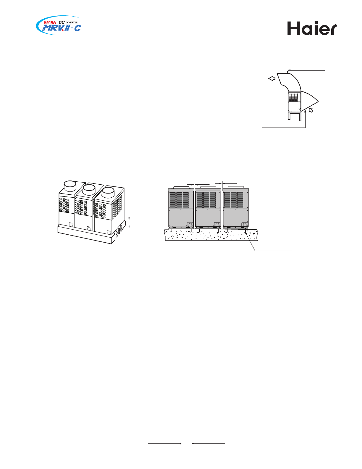
85 WJPJHX NRWXFPPFXNSR TPFHJ
over 977mm
over 977mm
air outlet snow
4proof cover
air inlet snow
4proof cover
over <77mm
refrigerant pipe
Q89 foundation screw
87MTA ; pieces
8=MTA = pieces
85 Nnstall adapter to change wind direction at the gas short circuit place5
95 [hen installing multiple units3 there should be enough air inlet place against
air in short circuit5
:5 Nn snowy area3 install the unit under the bracket or the snow4proof cover
against the accumulative snow on the unit5
;5 Io not install the unit at the place where the flammable gas will leak5
<5 Nnstall the unit at the strong enough place5
=5 Nnstall the unit at the flat place5
>5 [hen the refrigerant pipe is leaded out from the bottom of the uni3 the below
section should be a bracket with over <77mm height3 see below figure5
?5 [hen being installed at the place with strong wind3 set the air outlet of the
unit and the wind direction vertical5 Flso fix the unit with the screw5
@5 [hen opening the electric box cover for maintenance3 please fix the cover
with screw firmly5
7@
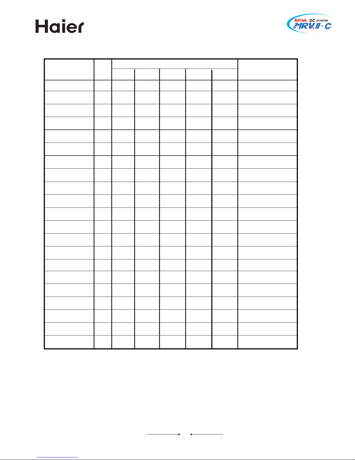
Hombination of outdoor units
FZ7?
UX] of Sutdoor unit
Hapacity/877[0
99=
9?7
::<
;77
;<7
<7=
<=7
=8<
=?7
>:7
?77
?<7
@77
@=7
8787
87?7
88:7
88?7
89:<
8:77
8:<7
MT
7?
87
89
8;
8=
8?
97
99
9;
9=
9?
:7
:9
:;
:=
:?
;7
;9
;;
;=
;?
87777
78777
77877
77787
77778
88777
79777
78877
78787
78778
77797
77788
77779
79787
79778
78797
78788
78779
77879
77789
7777:
Xotal UX]
FZ8=
FZ87 FZ89 FZ8;
8
8
8
8
8
9
9
9
9
9
9
9
9
:
:
:
:
:
:
:
:
87
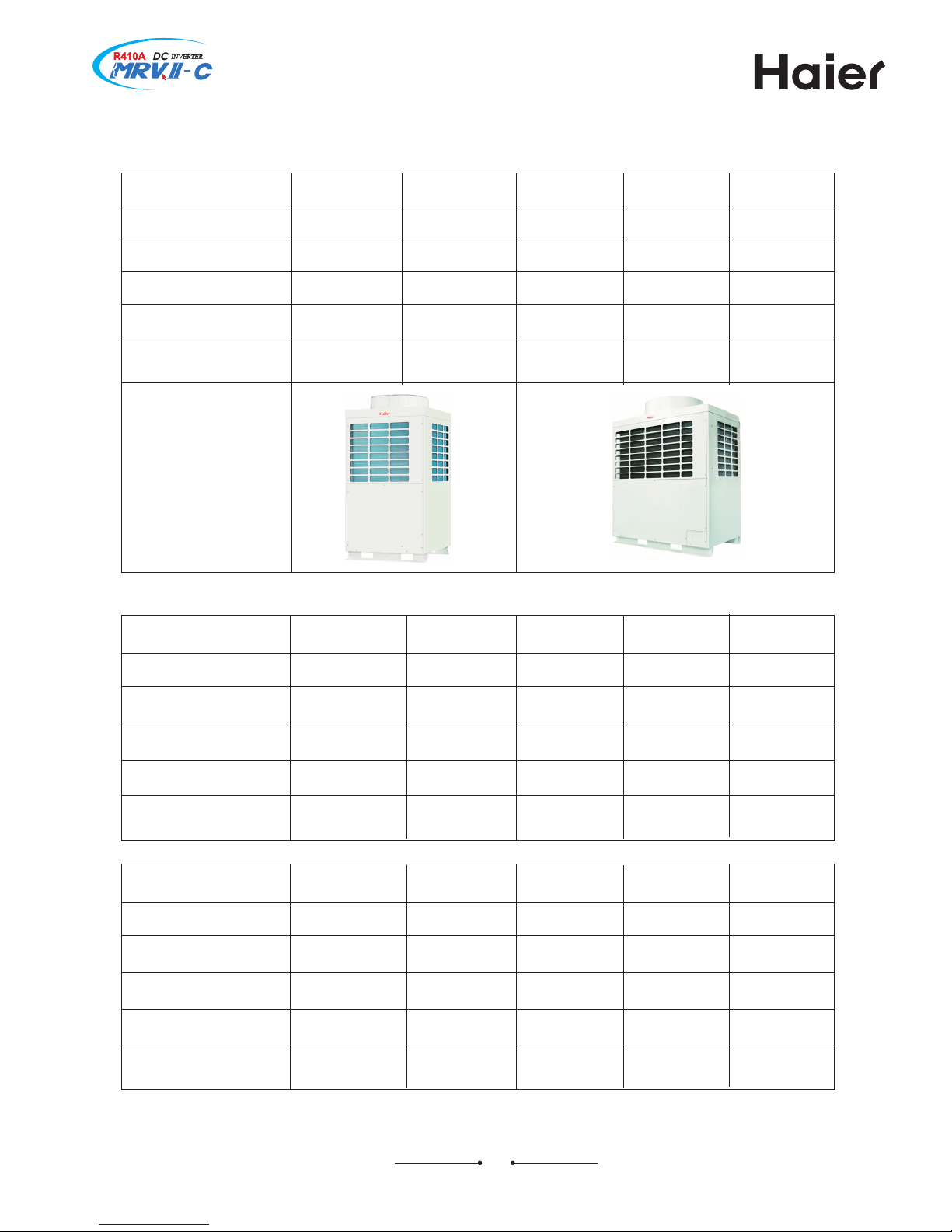
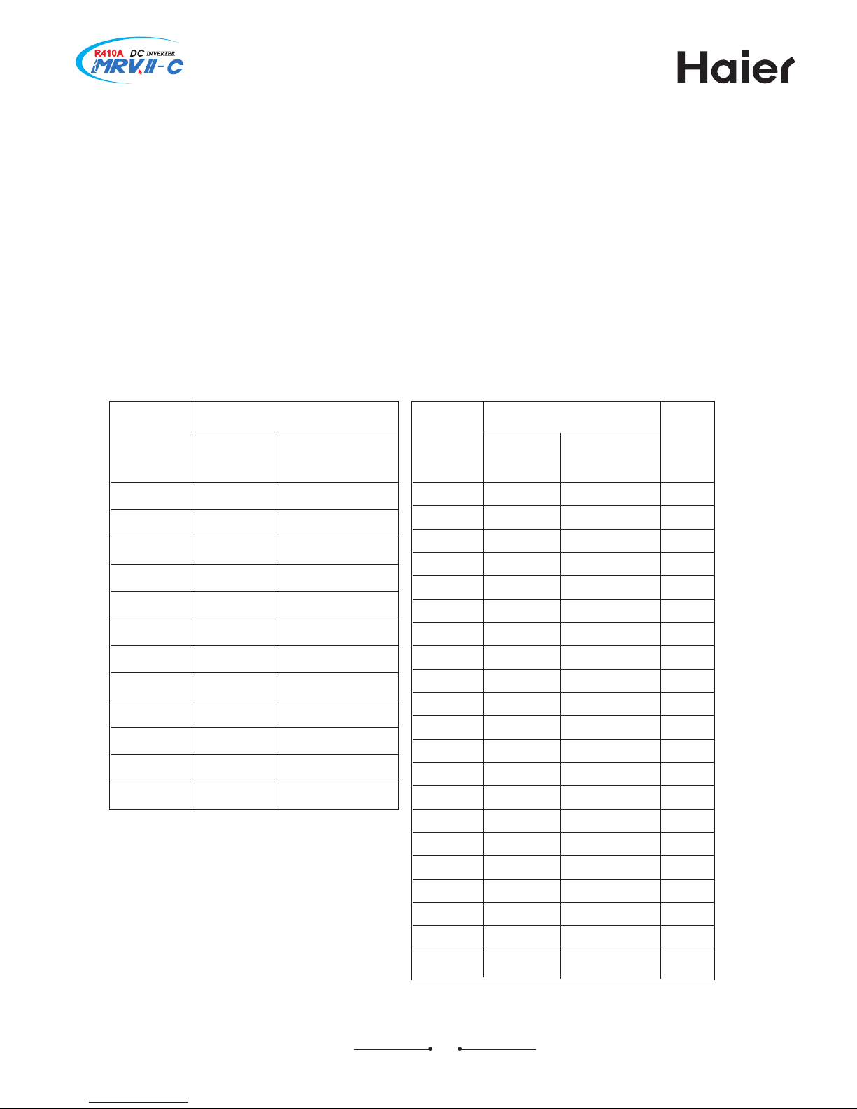
Jquipment series
85 Sutdoor units
95 Sutdoor units /combination of outdoor units0
corresponding MT
8?MT 97MT 99MT 9;MT 9=MT
model
FZ8?RQZJVF FZ97RQZJVF FZ99RQZJVF FZ9;RQZJVF FZ9=RQZJVF
cooling capacity
heating capacity
<75=
<=5<
<=57
=:57
=85<
=@
=?57
>=5<
>:57
?85<
max5 indoor quantity
total indoor capacity
/1877[0
9@
9<:{=<?
::
9?7{>9?
:=
:7?{?77
:@
:;7{??;
;:
:=<{@;@
corresponding MT
9?MT :7MT :9MT :;MT :=MT
model
FZ9?RQZJVF FZ:7RQZJVF FZ:9RQZJVF FZ:;RQZJVF FZ:=RQZJVF
cooling capacity
heating capacity
?757
@757
?<57
@<57
@757
87757
@=57
87?57
87857
88:57
max5 indoor quantity
total indoor capacity
/1877[0
;=
;77{87;7
<7
;9<{887<
<:
;<7{88>7
<=
;?7{89;?
<@
<7<{8:8:
corresponding MT
?MT 87MT 89MT 8;MT 8=MT
model
FZ7?RQZJVF FZ87RQZJVF FZ89RQZJVF FZ8;RQZJVF FZ8=RQZJVF
cooling capacity
heating capacity
995=
9<57
9?57
:85<
::5<
:>5<
;757
;<57
;<57
<757
appearance
max5 indoor quantity
total indoor capacity
/1877[0
8:
88:{9@;
8=
8;7{:=;
8@
8=?{;:=
9:
977{<97
9=
99={<??
88
corresponding MT
:?MT ;7MT ;9MT ;;MT ;=MT
model
FZ:?RQZJVF FZ;7RQZJVF FZ;9RQZJVF FZ;;RQZJVF FZ;=RQZJVF
cooling capacity
heating capacity
87?57
8985<
88:57
89=5<
88?57
8:85<
89:5<
8:>5<
8:757
8;<57
max5 indoor quantity
total indoor capacity
/1877[0
=:
<;7{8;7;
=;
<=<{8;=@
=;
<@7{8<:;
=;
=8?{8=7=
=;
=<7{8=@7
;?MT
FZ;?RQZJVF
8:<57
8<757
=;
=><{8><<
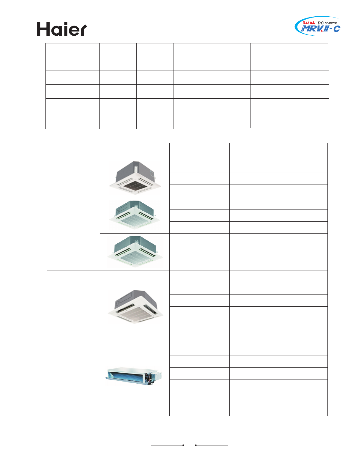
:5 Nndoor units
type appearance
model
cooling capacity
/O[0
heating capacity
/O[0
;4way cassette
type
;4way cassette
type
;4way cassette
type
low JWT duct type
FG7@9QHJVF
FG899QHJVF
FG8=9QHJVF
FG8?9QHJVF
FG9;9QHJVF
FG9?9QHJVF
FG:79QHJVF
FG:?9QHJVF
FG;?9QHJVF
FG8?9QJJVF
FG9;9QJJVF
FG9?9QJJVF
FG:79QJJVF
FG:?9QJJVF
FG;?9QJJVF
FI7>9QPJVF
FI7@9QPJVF
FI899QPJVF
FI8=9QPJVF
FI8?9QPJVF
FI9;9QPJVF
95?
:5=
;5<
<5=
>58
?57
@57
8859
8;57
<5=
>58
?57
@57
8859
8;57
959
95?
:5=
;5<
<5=
>58
:59
;57
<57
=5:
?57
@57
8757
895<
8=57
=5:
?57
@57
8757
895<
8=57
95<
:59
;57
<57
=5:
?57
89
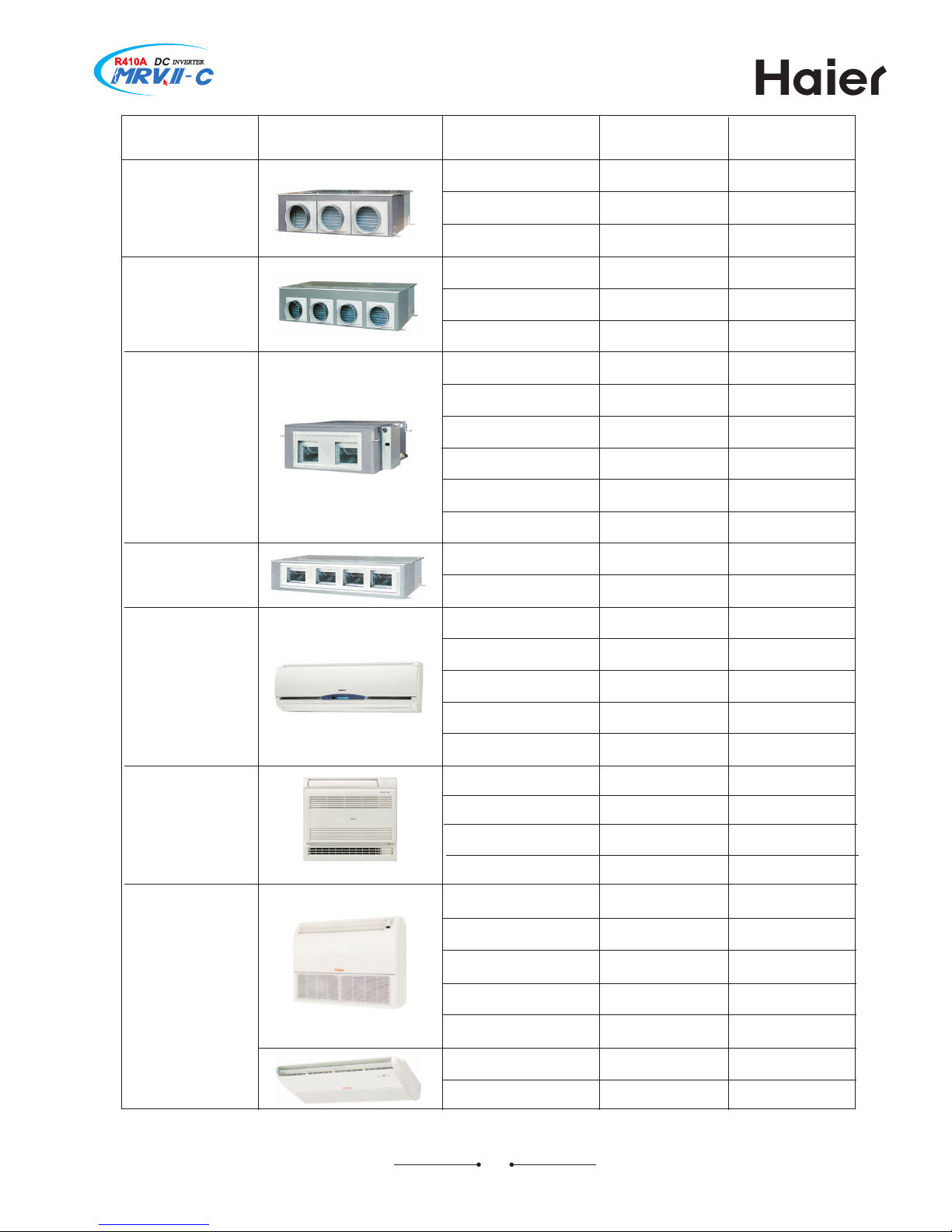
type appearance
model
cooling capacity
/O[0
heating capacity
/O[0
med JWT duct
type
med JWT duct
type
high JWT duct
type
high JWT duct
type
wall mounted
type
console type
convertible type
FI8?9QQJVF
FI9;9QQJVF
FI9?9QQJVF
FI:79QQJVF
FI:?9QQJVF
FI;?9QQJVF
FI8?9QMJVF
FI9;9QMJVF
FI9?9QMJVF
FI:79QMJVF
FI:?9QMJVF
FI;?9QMJVF
FI>99QMJVF
FI@=9QMJVF
FK7>9QFJVF
FK7@9QFJVF
FK899QFJVF
FK8?9QFJVF
FW7>9QHJVF
FW7@9QHJVF
FW899QHJVF
FW8=9QHJVF
FW8?9QHJVF
FH7@9QHJVF
FH899QHJVF
FH8=9QHJVF
FH8?9QHJVF
FH9;9QHJVF
FH:?9QKJVF
FH;?9QKJVF
<5=
>58
?57
@57
8859
8;57
=5:
?57
@57
8757
895<
8=57
<5=
>58
?57
@57
8859
8;57
995=
9?57
=5:
?57
@57
8757
895<
8=57
9<57
:857
959
95?
:5=
;5<
<5=
95<
:59
;57
<57
=5:
959
95?
:5=
<5=
95<
:59
;57
=5:
95?
:5=
;5<
<5=
>58
8859
8;
:59
;57
<57
=5:
?57
895<
8=
8:
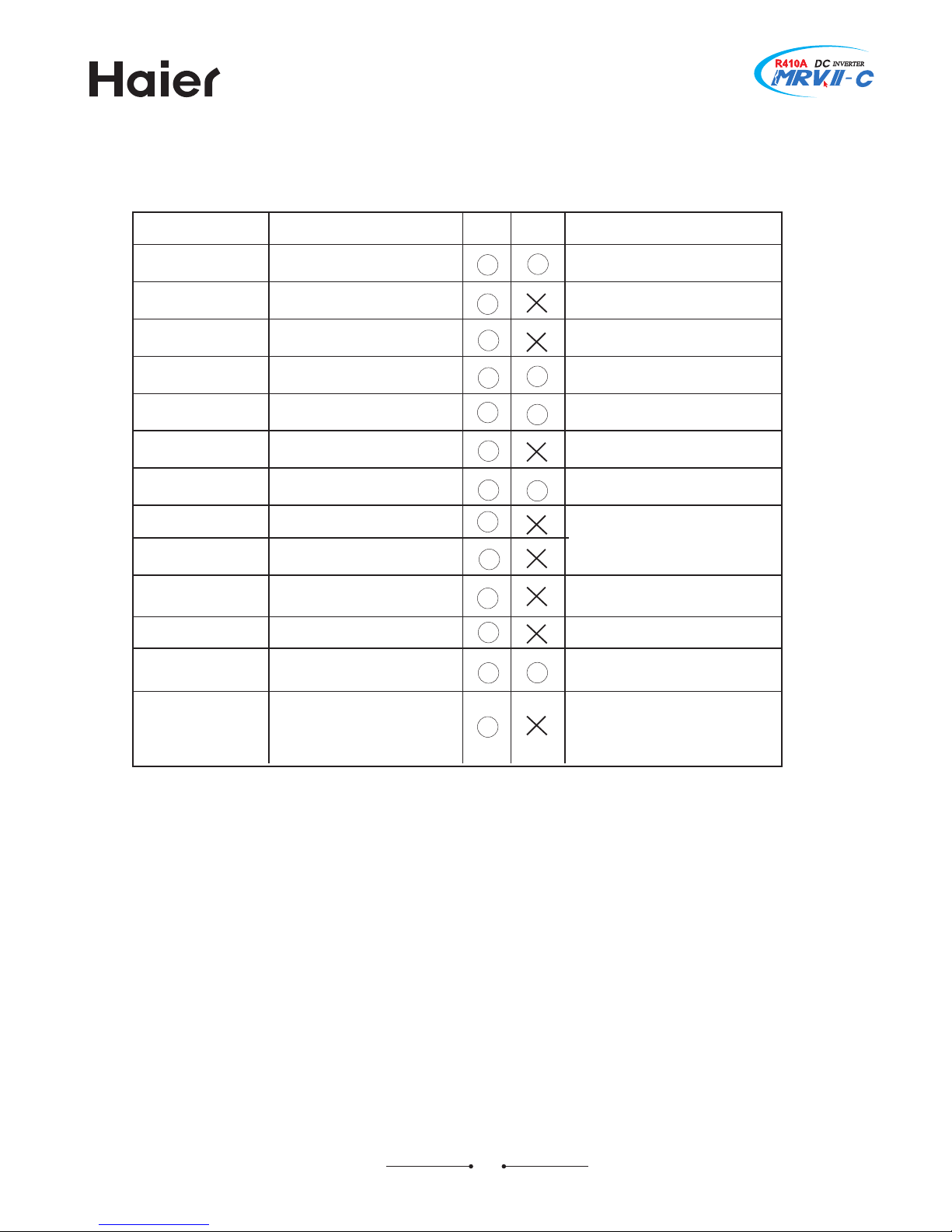
;5 Xools
RoteA Xhe pipes of V;87F connection with the same diameter can not be welded with the flared
joints5 ]ou must expand the diameter of pipe joint3 then weld the connecting pipe5
XSSP
knife
expander
spanner
flare tool
pipe bender
pressure gauge
welding torch
gauge manifold
charging hose
charging cylinder
leakage detector
TYVTSWJ
V99
V;87F
VJFWSR
electronic charging
scale
cut the pipe
enlarge the pipe
fasten the flare nut
flare the pipe
bend the pipe
used in leakage test
brazing the pipe
evacuation device
charging refrigerant
evacuation device
charging refrigerant
charging refrigerant
leakage detecting
for V;87F3 must enlarge the
projecting pipe
standard torque of 8693 <6?
pipe is larger
leakage test pressure is
higher
different pressure from V99A
max5A MT<5:Qpa min5A:5<Qpa
must ensure oil in vacuum
pump can not flow into the unit
when pump stops
vacuum pump with
one4way stop valve
V;87F can not be charged
as gas state
can not use freon detector
/HKHs or MHKHs03 V;87F
excludes Hl5 Yse the hydrogen
detector /or V8:;a detector0
Leneral tools/conventional tools can be used0
Gesides the above tools3 the following devices which service for V99 is necessary as the general tools5
85 torque wrench
95 pipe cutter
:5 reamer
;5 pipe bender
<5 level vial
=5 screwdriver
>5 hole core drill
?5 tape measure
@5 metal saw
Flso prepare the following equipment for the other installation procedureA
85 thermometer
95 ohmmeter
:5 voltmeter
Yse the exclusive tools for V;87F5
Qixing the different types of oil will cause the system working badly or clogged5
Xhe below table will compare the tools for V99 and V;87F5

8;
95 WFKJX] RSXJW
\FWSNSL
C Jnsure that all local3 national and international regulations are satisfied5
C Ffter the installation work has been completed3 perform a trial operation to check for possible
problem5 Kollow the owner.s manual to explain how to use and maintain the unit to the customer5
C Xurn off the main power supply switch /or breaker0 before any unit maintenance5
C Jnsure the customer keeps both the installation and owners manual together5
C Jnsure that all local3 national and international regulations are satisfied5
C Fsk the authorized dealer or qualified installation professional to install or maintain the air conditioner5
C Xurn off the main power switch or breaker before performing any electric work5
C Honnect all the electric wiries correctly5
C Iuring the transportation and installation of the air conditioner unit3 ensure that gaseous matter other
than the specified refrigerant does not enter into the refrigerant system5
C Io not modify the unit by removing any of the safety guards or by4passing any of the safety switches5
C Tlace the unit in the water or the moisture before installation may cause a short4circuit of electric
parts5
C Ffter unpacking the unit3 examine if there is possible damage5
C Io not install the unit at the place which will cause vibration5
C Xo avoid personal injury /with sharp edges03 be careful when handling parts5
C Terform installation work properly according to the installation manual5
C Nf the refrigerant gas has leaked in the transportation3 please ventilate the room immediately5
C Ffter installation3 please confirm the refrigerant system does not leak5
C Jlectric work must be performed by a qualified electrician according to the installation manual5 Qake
sure the air conditioner uses a special power supply5
C [hen connecting the installation wires3 be sure that all terminals are fixed5
C Honform to the regulation of the local electric company when wiring the power supply5
C Io not install the air conditioner in a location subject to a risk of exposure to a combustible gases5

8<
:5 HMJHO TSNRXW
Uqnsdbshnm cduhbd 4rtbg `r ghfg oqdrrtqd rvhsbg5
C Migh pressure switch is the device which can stop the unit automatically when the unit runs abnormally5
[hen the high pressure switch acts3 the cooling6heating mode will stop but the running PJI on wired
controller will be light still5 Xhe wired controller will display failure code5
[hen the following cases occur3 the protection device will actA
Nn cooling mode3 air outlet and air inlet of outdoor are clogged5
Nn heating mode3 indoor filter is sticked with ductB indoor air outlet is clogged5
[hen protection device acts3 please cut off the power source and re4start up after eliminating the
trouble5
\gdm onvdq hr e`hktqd
C [hen power is failure in running3 all the operations will stop5
Ffter being electrified again3 if with re4satrt up function3 the unit can resume to the state before power
off automaticallyB if without re4satrt up function3 the unti needs to be switched on again5
[hen abnormal occurs in running because of the thunder3 the lightning3 the interference of car or
radio3 etc3 please cut off the power source3 after eliminating the failure3 press +SR6SKK+ button to
start up the unit5
C Xhe heating mode adopts the heat pump type that absorbs outdoor heat energy and releases into
indoor5 Wo if outdoor temperature goes down3 the heating capacity will decrease5
Ideqnrshmf hm gd`shmf lncd
C Nn heating mode3 outdoor defrosting will affect the heating efficiency5 Xhe unit will defrost for about
9{87 minutes automatically3 at this time3 the condensate will flow from outdoor3 also in defrosting3
the vapour will appear at outdoor3 which is normal5 Nndoor motor will run at low speed or stop3 and
outdoor motor will stop5
Ygd tmhs nodq`shnm bnmchshnm
C Xo use the unit properly3 please operate the unit under the allowed condition range5
Nf operating beyond the range3 the protection device will act5
Xhe relative humidity should be lower than ?7-5 Nf the unit runs at the humidity over ?7- for a long
period3 the dew on the unit will drop down and the vapour will be blowed from air outlet5
Hgdbj adenqd nodq`shnm
C Xurn on the main power supply 89 hours or more before starting the operation5
C Hheck and ensure earth wiring is connnected5
C Hheck and ensure air filter is fitted to indoor unit5
Md`shmf b`o`bhsx
Hnloqdrrnq oqnsdbshnm
C Xhe outdoor unit will not operation within : minutes after the air conditioner restarts immediately after
stop or the power supply has been turned on5 Xhus the compressor will be protected5
8=
;5 OJ] TSNRXW KSV NRWXFPPFXNSR
Nn order to prevent problems before they arise3 carefully read the installation manual provided together
with the equipment before installation5
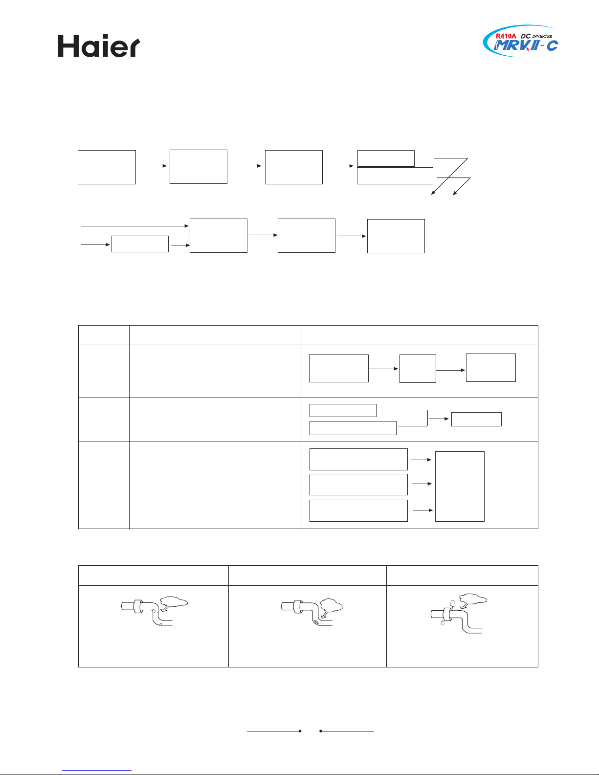
>8; Nmrs`kk`shnm oqnbdctqd 4enq xntq hmenql`shnm5
prepare work schedule
indoor unit installation
refrigerant piping installation
drain piping installation
duct work
insulation work
electric wiring work
outdoor unit foundation work
outdoor unit installation
refrigerant piping connection
leakage test
evacuation and drying
additional refrigerant charging
maintenance panel installation
trial running and adjustment
hand over
procedure
key points
list the installation work content
drafting of diagram
C control wiring system diagram
C refrigerant piping system diagram
C power wiring system diagram
sleeve installation
pay careful attention to the downward slope of the drain pipe
be sure to check the indoor model in order to avoid any
installation mistakes5 Nf the model has an installation pattern3
attach the pattern to the ceiling to mark the ceiling opening
position and to keep dust away5
make sure that the pipe system is dry3 clean and airtight5 [hen
brazing pipes3 blow out the system with nitrogen5
pipes should have downward slope of at least 868775
make sure that the pipe system is dry3 clean and airtight5 [hen
brazing pipes3 blow out the system with nitrogen5
be especially careful to close off all gaps where connections
are made to the indoor unit and at joints in the branching kit5
Io not forget the drain pipe5
use the 94core shielded wires for the control wires and use
individual power supply for the indoor and outdoor units5
set the switches correctly as indicated in the wiring diagram5
switch settings
make sure the unit is horizontal5
confirm that there should be enough service space and
adequate air flow around the outdoor5 Nndicate the unit model
clearly5
connect the pipes from the building to the outdoor3 and the
pipes between outdoors5
charge the system by nitrogen and keep for 9;hours3 the
system pressure should be ;7kf6cm
9
and without decrease5
Jvacuation the system through the checking joints on liquid
pipe stop valve and on the gas pipe stop valve with V;87F
specially vacuum pump5
record the additional amount added to the system5
confirm the maintenance panel in correct dimension and
position5 Peaving no gaps between the panel and the ceiling5
operate the indoor units one by one3 confirm the wires and the
pipes are correct5
8>
<5 VJKVNLJVFRX TNTJ NRWXFPPFXNSR
?8; \nqj oqnbdctqd
indoor unit
installation
sizing the
pipe
preliminary
installation
flaring
nitrogen gas blow
flushing
leakage
testing
evacuation
brazing
?8< Ygqdd oqhmbhokdr ne qdeqhfdq`ms ohodr
Vemember the below principlesA
results
dry
clean
airtight
C Qoisture /in the form of rainwater or water used
during installation0 getting inside of the pipes5
C Qoisture from condensation forming or seeping
into the pipes5
C Sxidation inside pipes during brazing
C Iirt3 dust3 or foreign matter getting inside pipes
C Toor brazing
C Toor flaring
how to prevent
careful handling
of pipes
charging
nitrogen
evacuation
nitrogen gas blow
careful handling of pipes
flushing
use of suitable material
/copper pipes3 solder3 etc0
perform basic work of
brazing carefully
perform basic work of flaring
carefully
leakage test
Xhe refrigerant pipes exampleA
keep dry
keep clean keep airtight
moisture
GFI
dirt
GFI
leakage
GFI
8?
?8= Hnmehql qdeqhfdq`ms ohod
85 Tlease select the refrigerant pipe of the below material5
QaterialA the phosphoric oxidize seamless copper pipe3 modelA H8997X4869M /diameter is over
8@57<0B H8997X47/diameter is below 8<5??05
95 Xhickness and specsA
Honfirm the pipe thickness and specs according to the pipe selection method/the unit is with V;87a3
if the pipe over 8@57< is 74type3 the pressure preservation will be bad3 thus it must be 869M type and
over the min5 thickness5
:5 Xhe branch pipe and the gather pipe must be from Maier5
;5 [hen installing the stop valve3 refer to the relative operation instruction5
<5 Xhe pipe installation should be in the allowable range5
=5 Xhe installation of branch pipe and gather pipe should be performed according to the relative manual5
Y`akd ;
capacity code
indoor
capacity
rank
equivalent
to MT
equivalent to
cooling capacity
75?
857
859<
85>
957
95<
:57
:59
;57
<57
?57
8757
959
95?
:5=
;5<
<5=
>58
?57
@57
8859
8;57
995=
9?57
Y`akd <
7> type
7@ type
89 type
8= type
8? type
9; type
9? type
:7 type
:? type
;? type
>9 type
@= type
capacity code
outdoor
model
equivalent
to MT
equivalent to
capacity
indoor
unit
quantity
FZ7?
FZ87
FZ89
FZ8;
FZ8=
FZ8?
FZ97
FZ99
FZ9;
FZ9=
FZ9?
FZ:7
FZ:9
FZ:;
FZ:=
FZ:?
FZ;7
FZ;9
FZ;;
FZ;=
FZ;?
?
87
89
8;
8=
8?
97
99
9;
9=
9?
:7
:9
:;
:=
:?
;7
;9
;;
;=
;?
995=
9?57
::5<
;757
;<57
<75=
<=57
=85<
=?57
>:57
?757
?<57
@757
@=57
87857
87?57
88:57
88?57
89:5<
8:757
8:<57
8:
8=
8@
9:
9=
9@
::
:=
:@
;:
;=
<7
<:
<=
<@
=:
=;
=;
=;
=;
=;
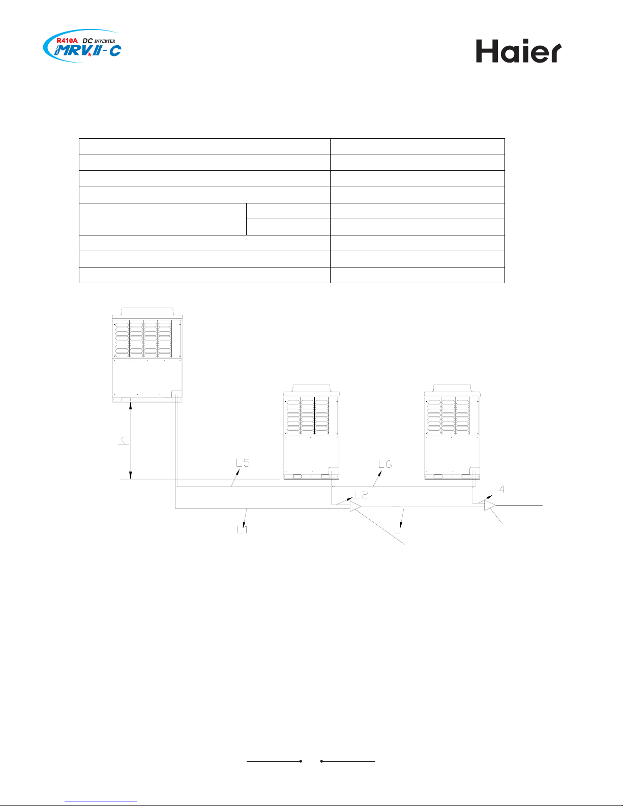
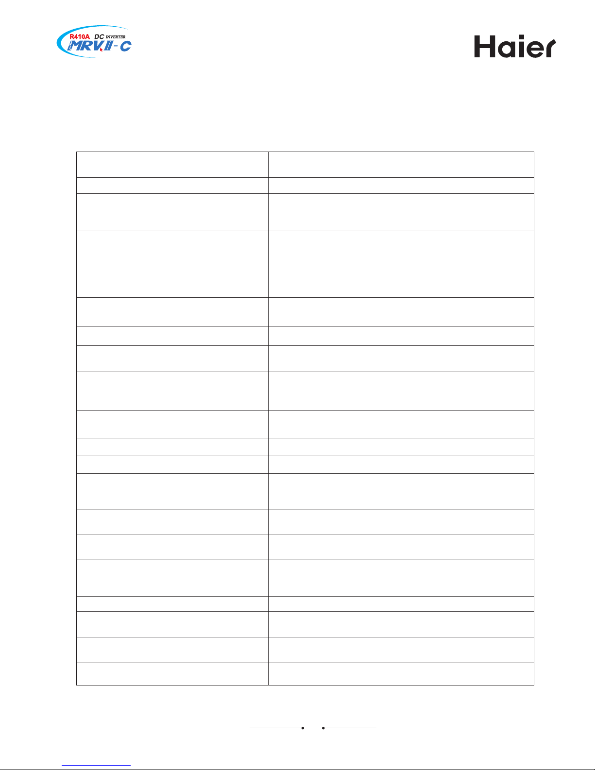
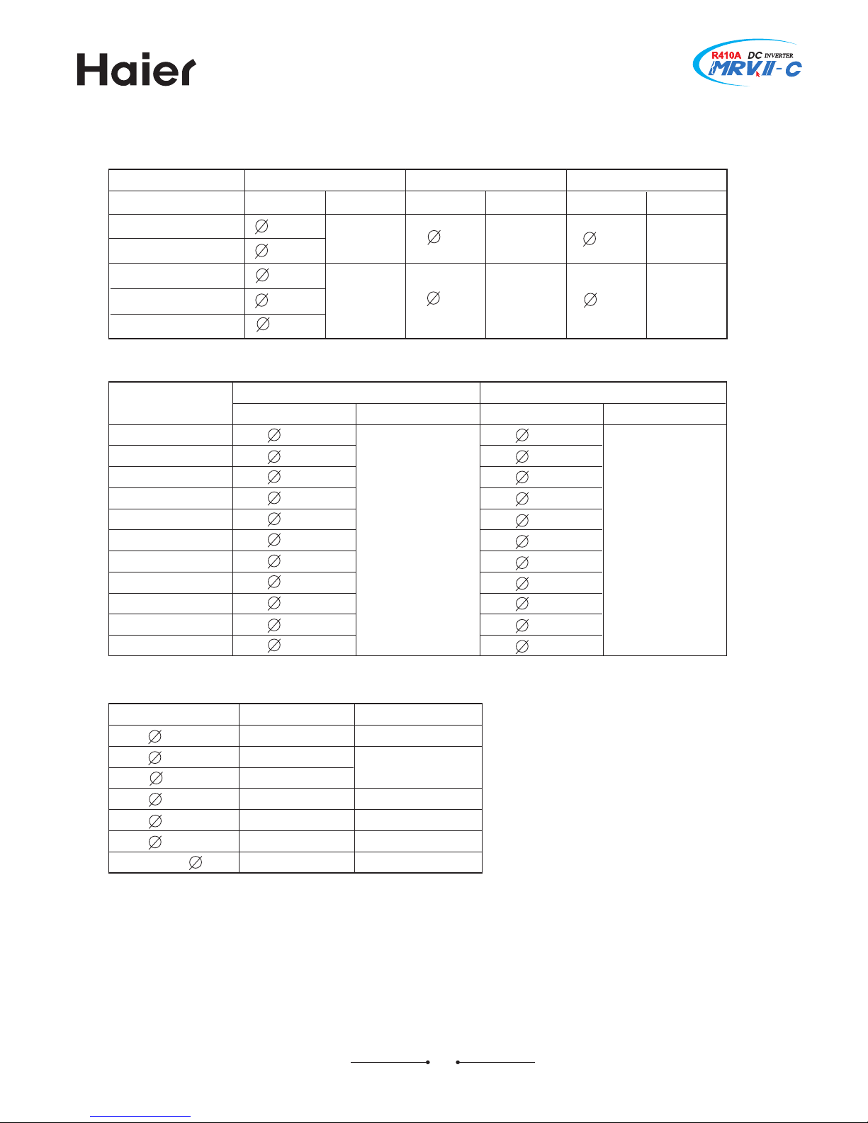
Allowable refrigerant piping length and height difference
a. Allowable pipe length and height difference
Single way total pipe length 300m
Single way max. pipe length Max. 150m
Main pipe between outdoor to 1st branch Max. 90m
Pipe length between outdoors Less than 10m to 1st branch pipe
Outdoor is upper Max. 50m Height difference between indoor and
outdoor
Outdoor is lower Max. 40m
Height difference between outdoors(in the same system) Within 5m (better be horizontal)
Max. pipe length from 1st branch pipe to indoor Max. 40m
Height difference between indoors Max. 15m
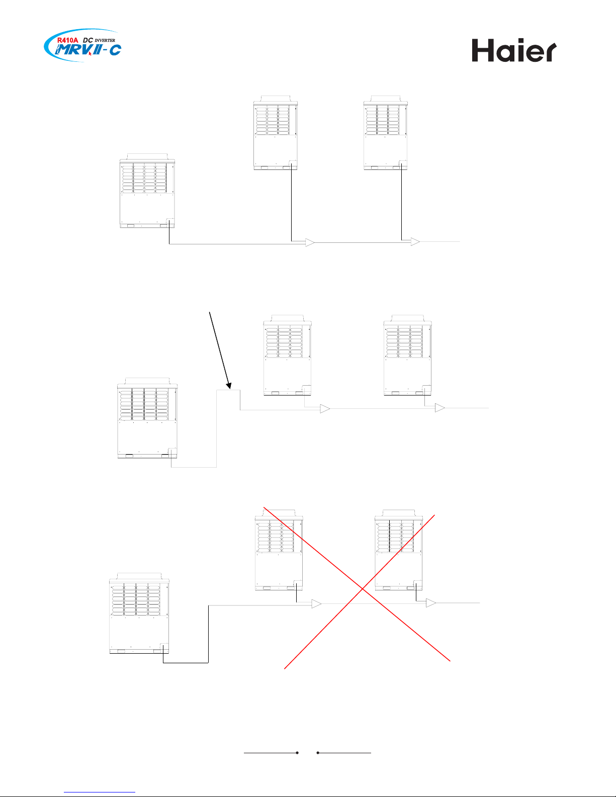
b. Pipe length between outdoors
3
outdoor1
outdoor2
outdoor
3
L1<10m,
L2+L3
<10m
Gas/liquid pipe:
1st gather pipe
2st gather pipe
Oil equalization pipe:
height difference between outdoors:
h
<5m
L5+L6
<10m
Note: a. HZG-30/A includes HZG-20/A;
b. The connection pipe among outdoors can not be higher than the stop valve position;
c. The connection pipe among outdoors should be horizontal or be in a certain angle as
the below figure (less than 15degree).
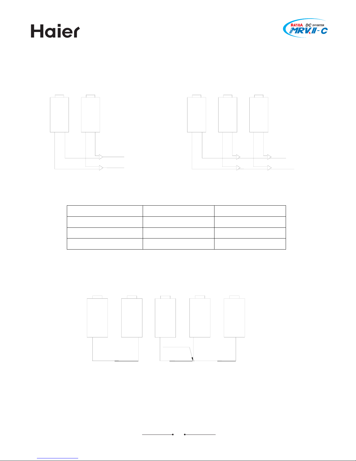
19
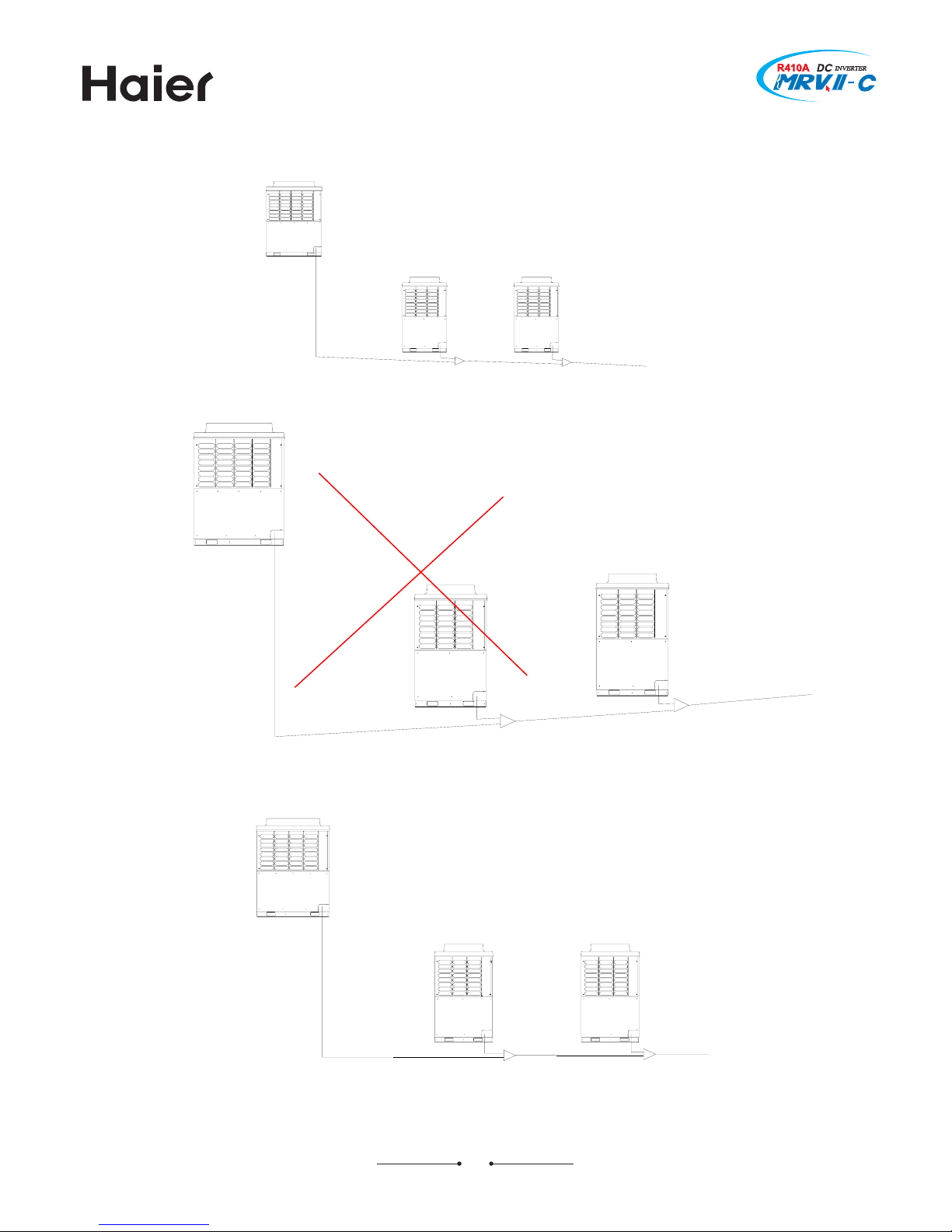
outdoor1
outdoor
2 outdoor3
outdoor1
outdoor2
outdoor3
Installation at high difference:
outdoor1
outdoor2 outdoor3
20
outdoor1
outdoor2
outdoor3
Oil trap (upright projecting pipe, 200mm high), as the figure:
outdoor1
outdoor2 outdoor3
Below is forbidden (compressor oil will flow into the lowest outdoor).
outdoor1
outdoor2
outdoor3
21
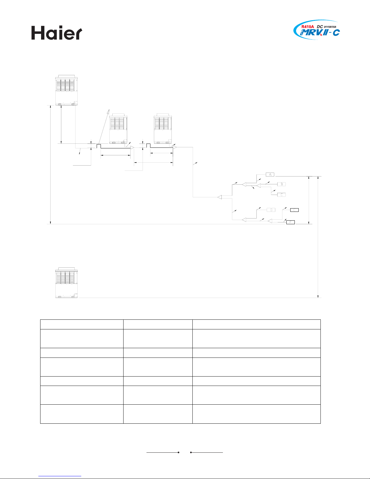
c. Allowable pipe length and height difference
Max. length Pipe in above figure
Single way total pipe length 300
L1+L2+ L3+ L4+ L5+ L6+ L7+L8+ L9+ L10+
L11+ L12+ L13+ L14+ L15
Single way max. pipe length 150 L1+L3+ L5+ L7+ L14+ L13
Max. pipe length after 1st
branch pipe
40 L7+L13+L14
Main pipe actual length 90 L5
Height difference between
indoors
15 ————
Height difference between
outdoors
5 ————
outdoor3
outdoor2
over 200mm
over 200mm
below 2m
below 2m
L7+L14+L13<40m
L1
L5
L14
L15
L13
L12
L11
L10
L9
L8
L7
L6
L2+L3
<10m
L4
L3
L2
L1
<10m
outdoor1
max. drop:5m
outdoor is lower, max. drop is 40m
max. drop:15m
outdoor is uppper,m ax. drop is 50m
when the distance between outdoors is over
2m, the oil trap must be set (upright projecting
pipe, 200mm high)
22
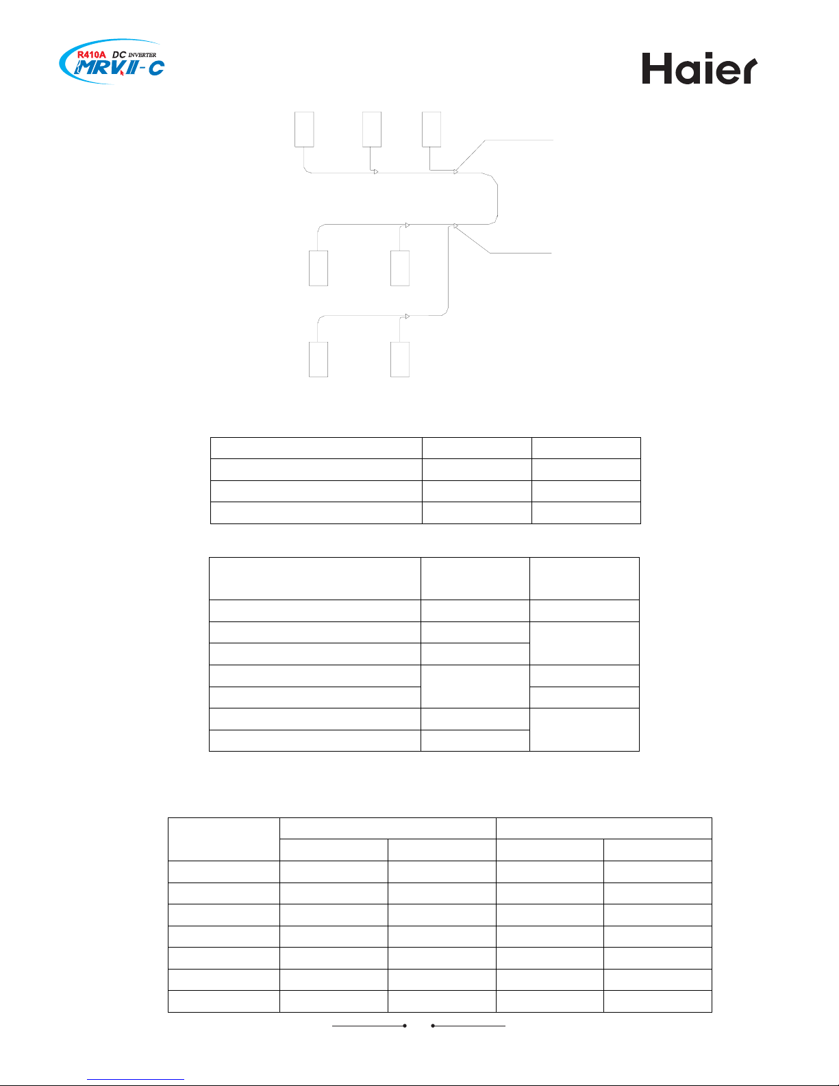
(2) Pipe specification:
aa
d
e
ee
c
b
aa
b
outdoor gather pipe
the first branch
a. Pipe “a” diameter (between indoor and branch pipe) (depends on indoor pipe, for wall
mounted unit, please refer to its specification)
Indoor(×100W) Gas pipe Liquid pipe
22~28 φ9.52 φ6.35
36~56 φ12.7 φ6.35
71~140 φ15.88 φ9.52
c. Pipe “c” diameter (main pipe, between outdoor gather pipe and the first branch pipe)
Main pipe Enlarged main pipe Outdoor
capacity
Gas pipe Liquid pipe Gas pipe Liquid pipe
22.6KW φ19.05 φ9.52 φ22.2 φ12.7
28.0KW φ22.2 φ9.52 φ25.4 φ12.7
33.5KW φ25.4 φ12.7 φ28.58 φ12.7
40.0KW φ25.4 φ12.7 φ28.58 φ12.7
45.0KW φ28.58 φ12.7 φ31.8 φ12.7
50.6KW φ28.58 φ15.88 φ31.8 φ15.88
56.0KW φ28.58 φ15.88 φ31.8 φ15.88
23
b. Pipe “b” diameter (between branch pipes)
When the later indoor capacity is less than 14.0KW, the specification of pipe b should refer
to the data in table a.
Total indoor capacity after the
branch pipe
Gas pipe Liquid pipe
14.0KW《<16.8KW
Φ15.88 Φ9.52
16.8KW《X<22.4KW
Φ19.05
22.4KW《X<33.0KW
Φ22.22
Φ9.52
Φ9.52
33.0KW《X<47.0KW
Φ12.7
47.0KW《X<71.0KW
Φ28.58
Φ15.88
71.0KW《X<101.0KW
Φ31.88
》101.0KW
Φ38.1
Φ19.05
61.5KW φ28.58 φ15.88 φ31.8 φ15.88
68.0KW φ28.58 φ15.88 φ31.8 φ15.88
73.0KW φ31.8 φ19.05 φ38.1 φ19.05
80.0KW φ31.8 φ19.05 φ38.1 φ19.05
85.0 KW φ31.8 φ19.05 φ38.1 φ19.05
90.0 KW φ31.8 φ19.05 φ38.1 φ19.05
96.0 KW φ31.8 φ19.05 φ38.1 φ19.05
101.0KW φ38.1 φ19.05 φ38.1 φ22.22
106.5KW φ38.1 φ19.05 φ38.1 φ22.2
113.0KW φ38.1 φ19.05 φ38.1 φ22.2
118.0KW φ38.1 φ19.05 φ38.1 φ22.2
123.5KW φ38.1 φ19.05 φ38.1 φ22.2
130.0 KW φ38.1 φ19.05 φ38.1 φ22.2
135.0KW φ38.1 φ19.05 φ38.1 φ22.2
Note: When the distance from outdoor to the longest indoor is over 90m, the main pipe
diameter should be enlarged.
d. Pipe “d” diameter (between gather pipes)
Total outdoor capacity
before the gather pipe
Liquid pipe (a, c) Gas pipe (b, d)
~68.0KW φ15.88 φ28.58
69.0~96.0KW
φ19.05 Φ31.8
97.0KW~ φ19.05 Φ38.1
e. Pipe “e” diameter (between outdoor and the gather pipe)
outdoor capacity Gas pipe Liquid pipe Oil equalization pipe
8HP φ19.05
10HP φ22.2
φ9.52
12, 14 HP φ25.4 φ12.7
16HP φ28.58 φ12.7
φ9.52
Copper pipe selection:
hardness softness Half-hardness
Outer
diameter
φ6.35 φ9.52 φ12.7 φ15.88 φ19.05 φ22.2 φ25.4 φ28.58 φ31.8 φ34.9 φ38.1 φ41.3
Min.
thickness
0.8 0.8 1.0 1.0 1.0 1.1 1.2 1.4 1.4 1.4 1.4 1.43
Note: If the copper pipe with outer diameter φ19.05 is coil pipe, the thickness should be
over 1.1.
24
9<
?8> Jpthu`kdms ohod kdmfsg ne admc ohod `mc aq`mbg ohod
Tipe size
bend pipe
branch pipe
=5:< @5<9 895> 8<5?? 8@58 :85?
758= 758? 7597 759< 75:< 75<<
75< 75< 75< 75< 75< 75<
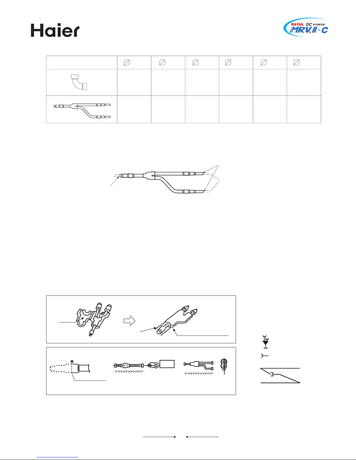
?8? Gq`mbg ohod
Nmsqnctbshnm ne aq`mbg ohodD
to outdoor unit
to next branch or indoor unit
field piping
field piping
inlet
outlet
outlet
RoteA
85 [hen connecting the gather pipe or branch pipe and the outdoor3 please pay attention to the outdoor pipe
dimension5
95 [hen adjusting the diameter among gather pipes and among the units3 please must execute at the branch
pipe side5
:5 Tlease install the branch pipe/gas6liqiud side0 in horizontal or vertical direction5
;5 [hen welding with hard solder3 please must blow nitrogen5 Nf not3 a number of oxide will be produced and
cause heavy damage5Gesides3to prevent water and dust into the pipe3 please make the brim as outer roll5
<5 Nf the size of the selected field pipe is different from that of the branch pipe3 the connecting pipe should be cut
with the pipe cutter5
WignA
inner diameter treatment
connection
between branches
connection for pipes
with different diameter
outer diameter treatment
Kloor
Trepare on field
Weal the connection and wrap the
heat insulator with adhesive tape
Fdhesive side
[rong
Morizontal
Vight
Kloor
Hut off pipe with the cutter
Hut off at the middle
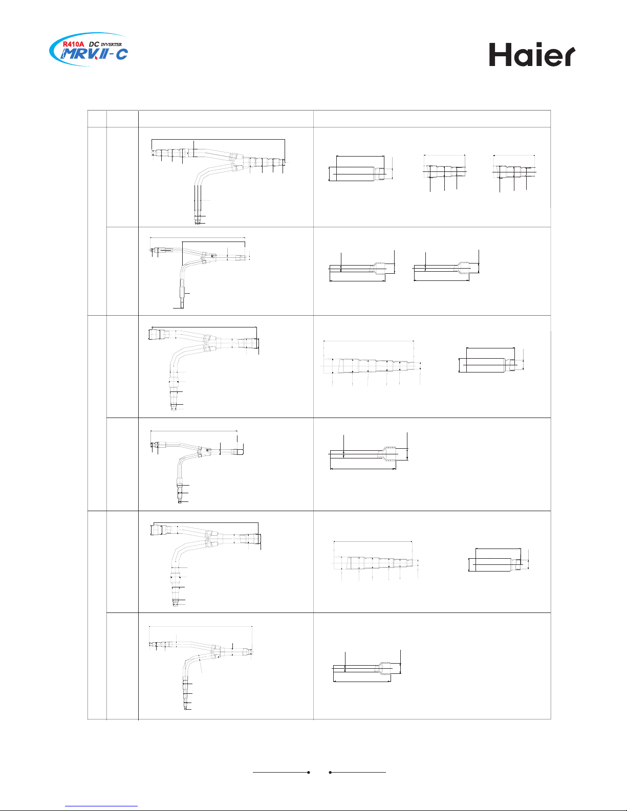
9=
Granch pipe/unitA mm3 NIA inner diameterB SIA outer diameter0
Wide
Honnection of manifold pipe
Las
Tipe
Piquid
Tipe
Las
Tipe
Las
Tipe
Piquid
Tipe
Piquid
Tipe
KUL4G::<F
KUL4G<7=FKUL4G>:7F
:?;
NI8=58
NI8@5:
NI995;
NI9<5;
SI99599
SI9<5;
NI995;
NI8@5:
NI8=58
SI8@57<
NI8=58
NI895@
9:?
NI=5<
NI@5>
NI@5>
NI=5<
SI895>
NI@5>
<<
SI=5:<
NI@5>
<<
SI=5:<
NI@5>
87;
SI8<5??
NI@5>
NI895@
87;
SI8<5??
877
NI@5>
SI895>
:9:
NI9?5?
SI9959
NI9<5=
SI9<5;
NI9<5=
NI9?5?
SI99599185<
NI8=58
NI995;
NI8@5:
NI895@
<<
SI=5:<
NI@5>
8?7
SI9?5<?
NI9<5=
NI995;
NI8@5:
NI8=58
NI895@
877
NI@5>
SI895>
9:?
NI@5>
NI@5>
NI=5<
SI895>
NI895@
NI895@
NI895@
<<
SI=5:<
NI@5>
:??
NI@5>
NI@5>
NI=5<
SI9<5;
NI895@
NI895@
NI8=58
SI8@57<
NI8=58
SI8@57<
NI8=58
:9:
NI9?5?
SI9959
NI9<5=
SI9<5;
NI9<5=
NI9?5?
SI99599185<
NI8=58
NI995;
NI8@5:
NI895@
8?7
SI9?5<?
NI9<5=
NI995;
NI8@5:
NI8=58
NI895@
877
NI@5>
SI895>
NI@5>
NI895@
9>
Gq`mbg ohod rdkdbshnmD
Yns`k b`o`bhsx ne hmcnnq tmhsr4;::\5
Qdrr sg`m ==?
Sns kdrr sg`m ==? `mc kdrr sg`m ?:@
Sns kdrr sg`m ?:@ `mc kdrr sg`m A=:
Sns kdrr sg`m A=:
Gq`mbg ohod lncdk
KVL7G==?F
KVL7G?:@F
KVL7GA=:F
KVL7G;=?:F
PP
PP
PP
PP
PP
PP
PP
PP
KUL4G8:<7F
Honnection of manifold pipe
<<
SI=5:<
NI@5>
;7<
NI@5>
SI9<5;
SI8@57<
NI8=58
NI895@
NI8=58
NI8@5:
NI995;
NI995;
NI8@5:
NI895@
NI@5>
NI=5<
:==
NI:?5:
SI:85><
SI9?5=
NI:9
SI:85><
NI:9
NI:?5:
NI9?5?
877
NI@5>
SI895>
8?7
SI9?5<?
NI9<5=
NI995;
NI8@5:
NI8=58
NI895@
8;7
SI:85><
NI9?5?
NI9
<5=
NI995;
8:?
SI99599
NI8=58
NI895@
NI8@5:
9?
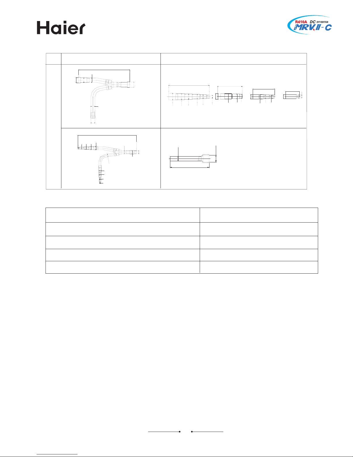
?8@ L`sgdq ohod
Lather pipe is used for combination of outdoor unit
M^L4976F/for 9 basic modules0B M^L4:76F/for : basic modules0
unitAmm3 NIA inner diameterB SIA outer diameter
RoteA Hut off the pipe from its middle when using
Qodel holm
Qark
Qanifold pipe
Nnsulation
material
holm
fieSXVU`
a
`
b
c
d
fieSYVU`
gcX[TZ
RVTX
RVTV[
gcXXTXX
RVTX
RVTV[
gcW_TW
RVTX
RVTV[
XVV
ZVZVWX
y
z
WV
gcW[T^^
RVTX[
RVTW
gcW_TV[
RVTX[
RVTW
ZV
gcW_TV[
RVTX[
RVTW
gcW[T^^
RVTX[
RVTW
RVTX[
RVTW
gc_T[X
RVTX[
RVTW
ZV ZV ZV
WV
ZXZ
_ZT[
RVTX[
RVTW
ZV
RVTX[
RVTW
ZV ZV
WV
RVTX[
RVTW
{
|
WV
gcW[T^^
RVTX[
RVTW
gcW_TV[
RVTX[
RVTW
ZV
RVTX[
RVTW
RVTX[
RVTW
RVTX[
RVTW
gc_T[X
RVTX[
RVTW
ZV ZV ZV
WV
ZXZ
_ZT[
RVTX[
RVTW
ZV
RVTX[
RVTW
ZV ZV
WV
RVTX[
RVTW
gcX[TZ
RVTX
RVTV[
gcXXTXX
RVTX
RVTV[
gcW_TW
RVTX
RVTV[
XVV
ZVZVWX
csxkpm
WXV
WZ
gcY[TW
RVTX
RVTV[
WXV
WZ
gcY^TW
RVTX
RVTV[
gcY^TW
RVTX
RVTV[
YV
gcY^TW
RVTX[
RVTW
[[V
\\]
WX
gcX^T\
RVTX
RVTV[
W[
W^_
gcWXT]
RVTX[
RVTW
gcWXT]
RVTX[
RVTW
csxkpm
gcX^T\
RVTX
RVTV[
gcX[TZ
RVTX
RVTV[
gcXXTXX
RVTX
RVTV[
gcW_TW
RVTX
RVTV[
Z\[
\ZV
W[
RVTX
RVTV[
WYX
gcX^T\
RVTX
RVTV[
gcY^TW
RVTX
RVTV[
gcYWT^
RVTX
RVTV[
gcX^T\
RVTX
RVTV[
gcX[TZ
RVTX
RVTV[
gcXXTXX
RVTX
RVTV[
gcW_TW
RVTX
RVTV[
Z\[
\ZV
W[
gcX^T\
RVTX
RVTV[
WYX
gcX^T\
RVTX
RVTV[
gcY^TW
RVTX
RVTV[
YWT^
RVTX
RVTV[
Qark
Honnection of manifold pipe
Las
side
Piquid
side
gcW_TV[
gcW[T^^
gcWXT]
gc_T[X
Las
side
Piquid
side
gcX^T\
Las
side
Piquid
side
Las
side
gcW[T^^
gcW[T^^
gcW_TV[
gcW_TV[
gcWXT]
gc_T[X
csxkpm
9@
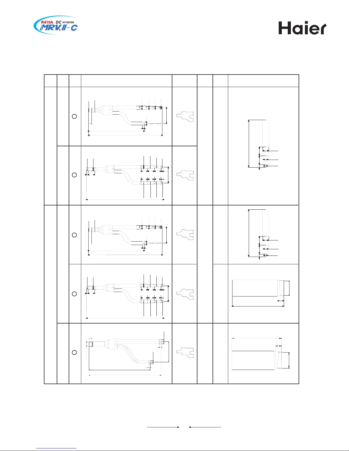
?8A Uhod rodbhehb`shnmr `mc bnmmdbshnm ldsgncr 4tmhsD ll5
H5 Tipe spec and the torque
diameter
Xhickness/mm0
75?
75?
857
857
857
859
Xorque/R5m0
8={97
;7{<7
@7{897
877{8;7
444
444
=5:<
@5<9
895>
8<5??
8@57<
9<5;
Rot less than 9?5<?
Qore than 85;
G5 Nndoor unit
Las pipe side
Qodel
Hapacity
7>
7@
89
8;
8=
8?
9;
9?
:9
:?
;?
@5<9
@5<9
895>
895>
895>
8<5??
8<5??
8<5??
Klared joint
Piquid pipe side
=5:<
=5:<
=5:<
=5:<
=5:<
@5<9
@5<9
@5<9
@5<9
@5<9
Iiameter
Honnecting
method
Iiameter
Honnecting
method
Klared joint
895>
8<5??
8<5??
F5 Sutdoor unit
Las pipe side Piquid pipe side Sil pipe side
FZ7?RQZJVF
FZ87RQZJVF
Iiameter
Honnecting
method
Grazing
Klared
joint
@5<9
Qodel
@5<9
FZ89RQZJVF
FZ8;RQZJVF
FZ8=RQZJVF
@5<9
895>
Iiameter
Honnecting
method
Iiameter
Honnecting
method
Grazing
Klared
joint
Klared
joint
Klared
joint
=5:<
8@57<
99599
9<5;
9<5;
9?5<?
(1) Outdoor pipe dimension
a
bb
ac
d
The pipe “a, b, c, d” should be confirmed as to the below table.
Former outdoor capacity Liquid pipe (a, c) Gas pipe (b, d)
~68.0KW φ15.88 φ28.58
69.0KW~96.0KW φ19.05 φ31.8
Over 97.0KW φ19.05 φ38.1
Note: When the single pipe length is over 90m, the above pipe should be enlarged as the
former information.
(2) Oil equalization pipe connection
oil equalization
pipe
φ9.52
T-shape
3-way pipe
oil equalization
pipe
φ9.52
18~32HP
34~48HP
18~32HP 34~48HP
Liquid pipe
Gas pipe
Liquid pipe
Gas pipe
30
Pipe dimension among outdoors
 Loading...