

Haier AV08NMSETA Service Manual

SYJS-11-2016 REV.A Edition: 2016-11
Service Manual
MRV S
II

CONTENTS
1. General Information ................................................................................................................. 1
1.1 Indoor units ........................................................................................................................ 1
1.2 Features ............................................................................................................................2
2. Specication ...........................................................................................................................6
3. Refrigerant Circuit..................................................................................................................12
4. Dimension .............................................................................................................................13
5. Wiring Diagram ...................................................................................................................... 14
6. Performance Curves..............................................................................................................15
7. Noise Level ............................................................................................................................ 17
8. Outdoor Installation ...............................................................................................................18
9. Electric Installation.................................................................................................................37
10. Trial Operation .....................................................................................................................40
11. Dip Switch Setting ............................................................................................................... 50
12. Digital Tube Display .............................................................................................................53
13. Failure Code ........................................................................................................................ 54
14. Troubleshooting ...................................................................................................................58
APPENDIX ................................................................................................................................76
11
1. General Information
1.1 Indoor units
4-WAY CASSETTE TYPE/PB-700lB
AB092MCERA
AB122MCERA
AB162MCERA
HIGH WALL EEV INSIDE
AS072MGERA AS162MGERA
AS092MGERA AS182MGERA
AS122MGERA AS242MGERA
4-WAY CASSETTE TYPE/PB-950JB
AB182MCERA
AB242MCERA
AB282MCERA
AB302MCERA
AB382MCERA
AB482MCERA
MED ESP DUCT TYPE (80/120Pa)
AD182MZERA
AD242MZERA
AD282MZERA
AD302MNERA
AD382MNERA
AD482MNERA
LOW ESP DUCT TYPE
AD072MLERA
AD092MLERA
AD122MLERA
AD162MLERA
AD182MLERA
AD242MLERA
MED ESP DUCT TYPE (50/96Pa)
AD182MMERA
AD242MMERA
AD282MMERA
AD302MMERA
AD382MMERA
AD482MMERA
HlGH ESP DUCT TYPE
AD182MHERA
AD242MHERA
AD282MHERA
AD302MHERA
AD382MHERA
AD482MHERA
AD722MHERA
AD962MHERA
CONVERTlBLE TYPE
AC092MCERA
AC122MCERA
AC162MCERA
AC182MCERA
AC242MCERA
AC282MFERA
AC302MFERA
AC382MFERA
AC482MFERA
SLIM LOW ESP DUCT
AD072MSERA
AD092MSERA
AD122MSERA
AD162MSERA
AD182MSERA
AD242MSERA
BUILIT-IN FLOOR STANDING
AE072MLERA
AE092MLERA
AE122MLERA
AE162MLERA
AE182MLERA
AE242MLERA
2-WAY CASSETTE/1055IB
AB072MBERA
AB092MBERA
AB122MBERA
AB162MBERA
AB182MBERA
CONSOLE TYPE
AF072MAERA
AF092MAERA
AF122MAERA
AF182MAERA
ROUND-WAY SMART AIR FLOW CASSETTE/ PB-950KC
AB072MRERA
AB092MRERA
AB122MRERA
AB162MRERA
AB182MRERA
AB242MRERA
AB282MRERA
AB302MRERA
AB382MRERA
AB482MRERA
AB602MRERA
DC SLIM LOW ESP DUCT
AD072MSERA(D)
AD092MSERA(D)
AD122MSERA(D)
AD162MSERA(D)
AD182MSERA(D)
AD242MSERA(D)
22
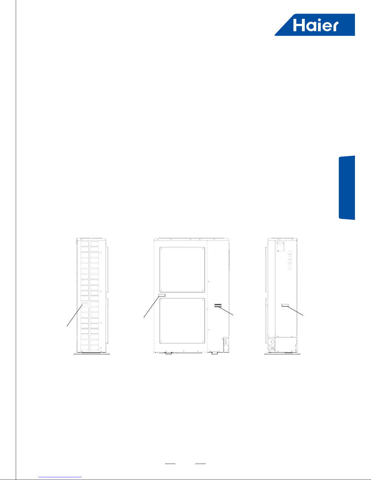
Outdoor structure
(8/10/12HP SIDE DISCHARGE)
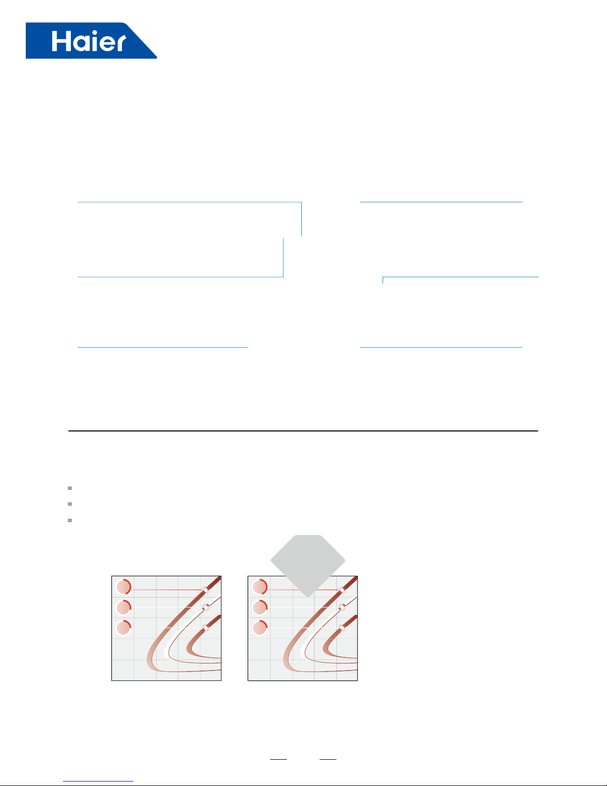
More Bigger Outdoor Capacity, More Flexible Application
High efciency DC fan motor Vector inverter control
Large diameter fan
Double pressure sensor
High efciency condenser
Twin rotary DC Inverter compressor
•
DC fan motor with stepless inverer
•
180 degrees sine wave vector control,
•
High precision control, to achieve high
•
570mm big diameter axial ow fan
•
Zigzag design, reduce airow disturbance,
DC fan and fan motor
DC inverter fan motor more higher efciency in part load running
■ 16-stage speed control; high efciency running especially in low speed
■ Efciency increase 45% comparing with AC motor and power input largely decrease big diameter fan
■ 570mm big diameter fan, more big air ow and more higher efciency
AC motor efciency DC motor efciency
100
80
60
40
20
0
100
80
60
40
20
0
0 200 400 600 800 1000 0 200 400 600 800 1000
45
%
85
%
95
%
87.5
%
35
%
25
%
efciency
45%
enhanced
Ø570mm fan
DC motor
control,efciency increase 45% comparing with
AC motor and power input largely decrease
64-bit operation
efciency and lower noise
air volume is bigger, the noise is lower
·
Equipped with high and low voltage
Pressure double sensors
·
Accurate Pressure control, the system run
more smoothly, more energy efciency
·
New type high efciency Ø8 inner
grooved tube
·
New hydrophilic corrugated ssure n,
high efciency
·
High chamber DC INVERTER twin rotary
conmpressor
·
Small vibration, low noise, high energy
effciency
1.2 Features
33
New DC inverter twin rotary compressor
■ Small torque change, good dynamic balance, the system runs stably,
little vibration, low noise, high efciency
■ More higher efciency in part load running
DC FAN
MOTOR
Strong
magnetic
rotor, small
vortex of
refrigerant
Low noise level
Night quiet operation function
Noise can be reduced to 45dB (A)
Low noise operation
■ DC INVERTER compressor, smooth operation, no need frequent start the compressor, effectively reduce the
noise outdoor
■ Vector inverter control, more precise control
■ DC fan motor, motor bracket used the non-resonance structure, ensure smooth running of the motor, reduce
operating noise
■ Big diameter fan, design according to aviation quieter principle
DC motor
High reliability
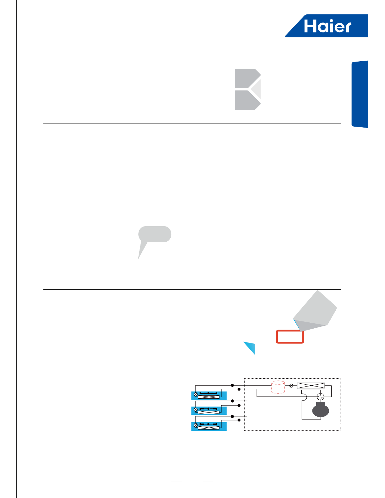
Refrigerant automatically reclaim technology
Set refrigerant automatically reclaim through dip switch,
the refrigerant in indoor and pipe can be automatically
return to outdoor, convenient in maintenance and
reducing waste of refrigerant, reduce customer
maintenance cost, improve the efciency of after-sales
maintenance
Refrigerant control technology
Refrigerant control technology without high pressure
accumulator, reducing the refrigerant volume and
enhancing the running efciency
Outdoor
Indoor
Indoor
Indoor
Without accumulator
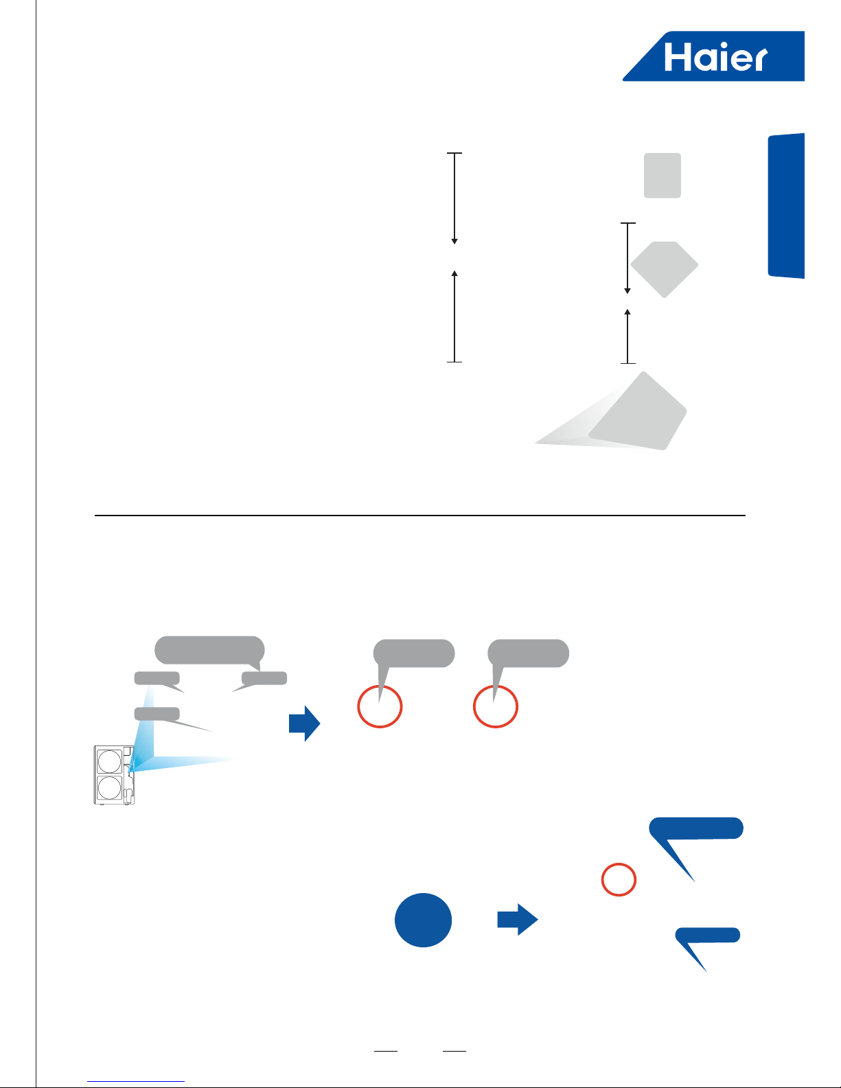
Compressor
Press these 2
buttons
5 seconds
General Information
44
High reliability
Air inlet grill design on right side panel
Air inlet grill design, reducing the module temperature and avoid air dust into air conditioner
High and Low Double Pressure Sensor
Double pressure sensor with PID control technology
Together with high speed communication to realize the quick start of compressor and more precise control, the
temperature can be control ±0.5°C
Reducing the module
temperature
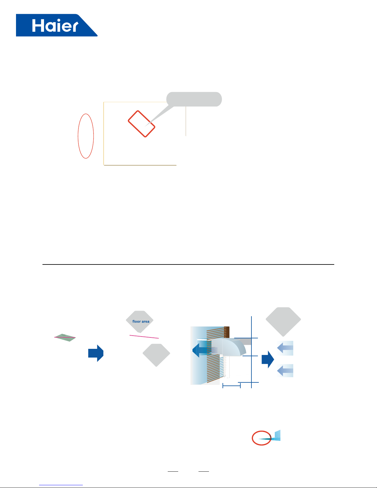
Easy installation
Compact side discharge design,
Big capacity, small oor area
Small oor area, only 0.42m², 43% oor area
can be reduced
Compact side discharge design
No need additional ventilation hood comparing with top
discharge unit
0.745m
2
0.42m
2
43%
reduced
188mm
height
reduced
0.8m
1.8m
0.77m
Good solution
for
narrow space
4 Way pipe connection
Front, rear, right, down 4 way pipe connection, exible installation
55
General Information
Long pipe length, high height drop
■ Total pipe length: 300m
■ Single pipe length: Max. 175m
■ From outdoor to the rst branch pipe: 135m
■
■ Height drop between indoor units: 15m
■ Separate Refrigerant Charging Valve
■ Easy for refrigerant charging
Separate
refrigerant
charging
valve
15m
50m
Single
pipe
length
175 m
length
300
m
Total pipe
Easy service
Parameter display panel
■ The rst original parameter display panel on the side
■ The parameter can be observed directly by opening the protective cover in case of maintenance, to
avoid removing the repair board
Easy maintenance for control
■ The control box is in front, reserving space
Parameter
display
Cover
AC FAN
Control PCB
Main PCB
Traditional products need to
open the front panel or top
control box cover for
maintenance
DC FAN
Control PCB
Maintenance
from the top
Hinge design
Difficult to
maintenance
from the front
From the rst branch to the farthest indoor
door unit: 40m Height drop: 50m (outdoor
above)/40m (outdoor below)
108mm between control box and toppanel,
easy maintenance from the top Control box is
with hinge design, easy to open for maintenance
66
2. Specication
Model AV08NMSETA
Power supply Ph/V/Hz 3/380~400/50/60
Cooling
Rated capacity kW 22.6
Rated capacity kBtu/h 77.1
Rated power input kW 5.79
Max. power input kW 10.42
EER 3.90
Rated current A 9.6
Max. current A 17.2
Heating
Rated capacity kW 25
Rated capacity kBtu/h 85.3
Rated power input kW 5.43
Max. power input kW 9.78
COP 4.60
Rated current A 9
Max. current A 16.2
Compressor
Brand MITSUBISHI ELECTRIC
Model LNB53FCAMC
Type Rotary
Compressor quantity 1 INV
Capacity W 16860
Power Input W 5200
Rated current (RLA) A 15.4
Speed rps 60.0
Crankcase Heater W 60.0
Refrigerant oil brand IDEMITSUKOSAN CO.,LTD
Refrigerant oil type FV50S
Refrigerant oil charge ml 1700.0
Outdoor fan
motor
Brand NIDEC TECHNO
Model SIC-81FW-F1145-1
Voltage 310.0
IP Class IP42
Type DC
Insulation class E
Safe class I
Power Input W 145.0
Output W 200.0
Rated current A 0.6
Capacitor μF /
Speed rpm 147-770
Outdoor fan
Brand SHUNWEI
Model /
Material Plastic
Type Axial
Diameter mm 570
Height mm 202
77
Specication
Model AV08NMSETA
Outdoor coil
Number of rows 2
Tube pitch (a)×row
pitch (b)
mm 19.05×22
Fin spacing mm 1.4
Fin type (code) HYDROPHILIC ALUMINIUM
Fin coating type Optional Clear lacquer
Salt spray test
duration
Hour 168
Tube outside dia.and
type
INNERGROOVE TUBE
mm Ф8
Coil length × height mm 1122×1584
Number of circuits 14
Cabinet coating
Coating type Powder coating
Salt spray test
duration
Hour 72
Sheet metal material Hot zinc plate
Sheet metal thickness mm 1.0
Control panel enclosure IP class Standard IP24
Outdoor air ow m
3
/h 10000
Outdoor sound level (sound pressure level ) dB (A) 55
Outdoor sound level (sound power level ) dB (A) 66
Outdoor unit
Dimension (W*H*D) mm 1050×400×1636
Packing (W*H*D) mm 1150×510×1790
Net weight kg 168
Gross weight kg 183
Refrigerant
Type R410A
Charged volume kg 7.4
Throttle type EXV
Design pressure MPa 4.15
Refrigerant piping
Liquid pipe mm 9.52
Gas pipe mm 19.05
Total pipe lenth m 300
Max. pipe length
(Equivalent/ Actual)
m 175/150
Max.Diff. indoor/
outdoor unit
m
50 (Outdoor higher than indoor)
40 (Indoor higher than outdoor)
Max.Diff. indoor/indoor
unit
m 15
Connectable indoor unit ratio % 50%~130%
Maximum indoor units Piece 13
Connection wiring
Power wiring mm
2
6.0
Signal wiring mm
2
Shield wire: (0.75-2)*2
Operation Range °C
Cooling: -15~43
Heating: -15~21
■ Norminal condition: indoor temperature (cooling): 27DB (°C)/19WB (°C), indoor temperature (heating): 20DB
(°C)
/14.5 WB(°C) Outdoor temperature (cooling): 35DB (°C)/24WB ( °C ), outdoor temperature (heating): 7DB
(°C)
/6WB (°C
)
The noise level will be measured in the third octave band limited values in the semi-anechoic chamber, using a
Real Time Analyser calibrated sound intensity meter. It is a sound pressure noise level.
88
Model AV10NMSETA
Power supply Ph/V/Hz 3/380~400/50/60
Cooling
Rated capacity kW 28
Rated capacity kBtu/h 95.5
Rated power input kW 8
Max. power input kW 14.4
EER 3.50
Rated current A 13.2
Max. current A 23.8
Heating
Rated capacity kW 31.5
Rated capacity kBtu/h 107.5
Rated power input kW 7.5
Max. power input kW 12.4
COP 4.20
Rated current A 12.4
Max. current A 22.3
Compressor
Brand MITSUBISHI ELECTRIC
Model LNB53FCAMC
Type Rotary
Compressor quantity 1 INV
Capacity W 16860
Power Input W 5200
Rated current (RLA) A 15.4
Speed rps 60.0
Crankcase Heater W 60.0
Refrigerant oil brand IDEMITSUKOSAN CO.,LTD
Refrigerant oil type FV50S
Refrigerant oil charge ml 1700.0
Outdoor fan
motor
Brand NIDEC TECHNO
Model SIC-81FW-F1145-1
Voltage 310.0
IP Class IP42
Type DC
Insulation class E
Safe class I
Power Input W 145.0
Output W 200.0
Rated current A 0.6
Capacitor μF /
Speed rpm 147-770
Outdoor fan
Brand SHUNWEI
Model /
Material Plastic
Type Axial
Diameter mm 570
Height mm 202
99
Specication
■ Norminal condition: indoor temperature (cooling): 27DB (°C)/19WB (°C), indoor temperature (heating): 20DB
(°C)
/14.5 WB(°C) Outdoor temperature (cooling): 35DB (°C)/24WB ( °C ), outdoor temperature (heating): 7DB
(°C)
/6WB (°C
)
The noise level will be measured in the third octave band limited values in the semi-anechoic chamber, using a
Real Time Analyser calibrated sound intensity meter. It is a sound pressure noise level.
Model AV10NMSETA
Outdoor coil
Number of rows 2
Tube pitch (a)× row
pitch (b)
mm 19.05×22
Fin spacing mm 1.4
Fin type (code) HYDROPHILIC ALUMINIUM
Fin coating type Optional Clear lacquer
Salt spray test
duration
Hour 168
Tube outside dia.and
type
INNERGROOVE TUBE
mm Ф8
Coil length × height mm 1122×1584
Number of circuits 14
Cabinet coating
Coating type Powder coating
Salt spray test
duration
Hour 72
Sheet metal material Hot zinc plate
Sheet metal thickness mm 1.0
Control panel enclosure IP class Standard IP24
Outdoor air ow m
3
/h 10000
Outdoor sound level (sound pressure level ) dB (A) 58
Outdoor sound level (sound power level ) dB (A) 69
Outdoor unit
Dimension (W*H*D) mm 1050×400×1636
Packing (W*H*D) mm 1150×510×1790
Net weight kg 168
Gross weight kg 183
Refrigerant
Type R410A
Charged volume kg 7.4
Throttle type EXV
Design pressure MPa 4.15
Refrigerant piping
Liquid pipe mm 9.52
Gas pipe mm 22.22
Total pipe lenth m 300
Max. pipe length
(Equivalent/ Actual)
m 175/150
Max.Diff. indoor/
outdoor unit
m
50 (Outdoor higher than indoor)
40 (Indoor higher than outdoor)
Max.Diff. indoor/indoor
unit
m 15
Connectable indoor unit ratio % 50%~130%
Maximum indoor units Piece 16
Connection wiring
Power wiring mm
2
10.0
Signal wiring mm
2
Shield wire:(0.75-2)*2
Operation Range °C
Cooling: -15~43
Heating: -15~21
1010
Model AV12NMSETA
Power supply Ph/V/Hz 3/380~400/50/60
Cooling
Rated capacity kW 33.5
Rated capacity kBtu/h 114.3
Rated power input kW 9.75
Max. power input kW 15.4
EER 3.44
Rated current A 16.4
Max. current A 26
Heating
Rated capacity kW 37.5
Rated capacity kBtu/h 128
Rated power input kW 9.62
Max. power input kW 15
COP 3.90
Rated current A 16.2
Max. current A 25.3
Compressor
Brand MITSUBISHI ELECTRIC
Model LNB53FCAMC
Type Rotary
Compressor quantity 1 INV
Capacity W 16860
Power input W 5200
Rated current (RLA) A 15.4
Speed rps 60.0
Crankcase heater W 60.0
Refrigerant oil brand IDEMITSUKOSAN CO.,LTD
Refrigerant oil type FV50S
Refrigerant oil charge ml 1700.0
Outdoor fan
motor
Brand NIDEC TECHNO
Model SIC-81FW-F1145-1
Voltage 310.0
IP class IP42
Type DC
Insulation class E
Safe class I
Power input W 145.0
Output W 200.0
Rated current A 0.6
Capacitor μF /
Speed rpm 147-770
Outdoor fan
Brand SHUNWEI
Model /
Material Plastic
Type Axial
Diameter mm 570
Height mm 202

1111
Specication
Model AV12NMSETA
Outdoor coil
Number of rows 2
Tube pitch (a)× row
pitch (b)
mm 19.05×22
Fin spacing mm 1.4
Fin type (code) HYDROPHILIC ALUMINIUM
Fin coating type Optional Clear lacquer
Salt spray test duration Hour 168
Tube outside dia.and
type
INNERGROOVE TUBE
mm Ф8
Coil length × height mm 1122×1584
Number of circuits 14
Cabinet coating
Coating type Powder coating
Salt spray test duration Hour 72
Sheet metal material Hot zinc plate
Sheet metal thickness mm 1.0
Outdoor air ow m
3
/h 10000
Outdoor sound level (sound pressure level ) dB (A) 60
Outdoor sound level (sound power level ) dB (A) 71
Outdoor unit
Dimension (W*H*D) mm 1050×400×1636
Packing (W*H*D) mm 1150×510×1790
Net weight kg 168
Gross weight kg 183
Refrigerant
Type R410A
Charged volume kg 7.4
Throttle type EXV
Design pressure MPa 4.15
Refrigerant piping
Liquid pipe mm 12.7
Gas pipe mm 25.4
Total pipe lenth m 300
Max. pipe length
(Equivalent/ Actual)
m 175/150
Max.Diff. indoor/outdoor
unit
m
50 (Outdoor higher than indoor)
40 (Indoor higher than outdoor)
Max.Diff. indoor/indoor
unit
m 15
Connectable indoor unit ratio % 50%~130%
Maximum indoor units Piece 16
Connection wiring
Power wiring mm
2
16.0
Signal wiring mm
2
Shield wire:(0.75-2)*2
Operation range °C
Cooling: -15~43
Heating: -15~21
■ Norminal condition: indoor temperature (cooling): 27DB (°C)/19WB (°C), indoor temperature (heating): 20DB
(°C)
/14.5 WB(°C) Outdoor temperature (cooling): 35DB (°C)/24WB ( °C ), outdoor temperature (heating): 7DB
(°C)
/6WB (°C
)
The noise level will be measured in the third octave band limited values in the semi-anechoic chamber, using a
Real Time Analyser calibrated sound intensity meter. It is a sound pressure noise level.
1212
3. Refrigerant Circuit
Ambient temp. sensor Ta
Electronic expansion valve PMV
Spray valve SV2
Suction temperature sensor Ts
Unload valve SV1
Discharging temperature sensor Td
Gas pipe valve
Oil temperature sensor Toil
Ambient temp. sensor Ta
Gas pipe valve
1313
Dimension
4. Dimension
1050
D
1414
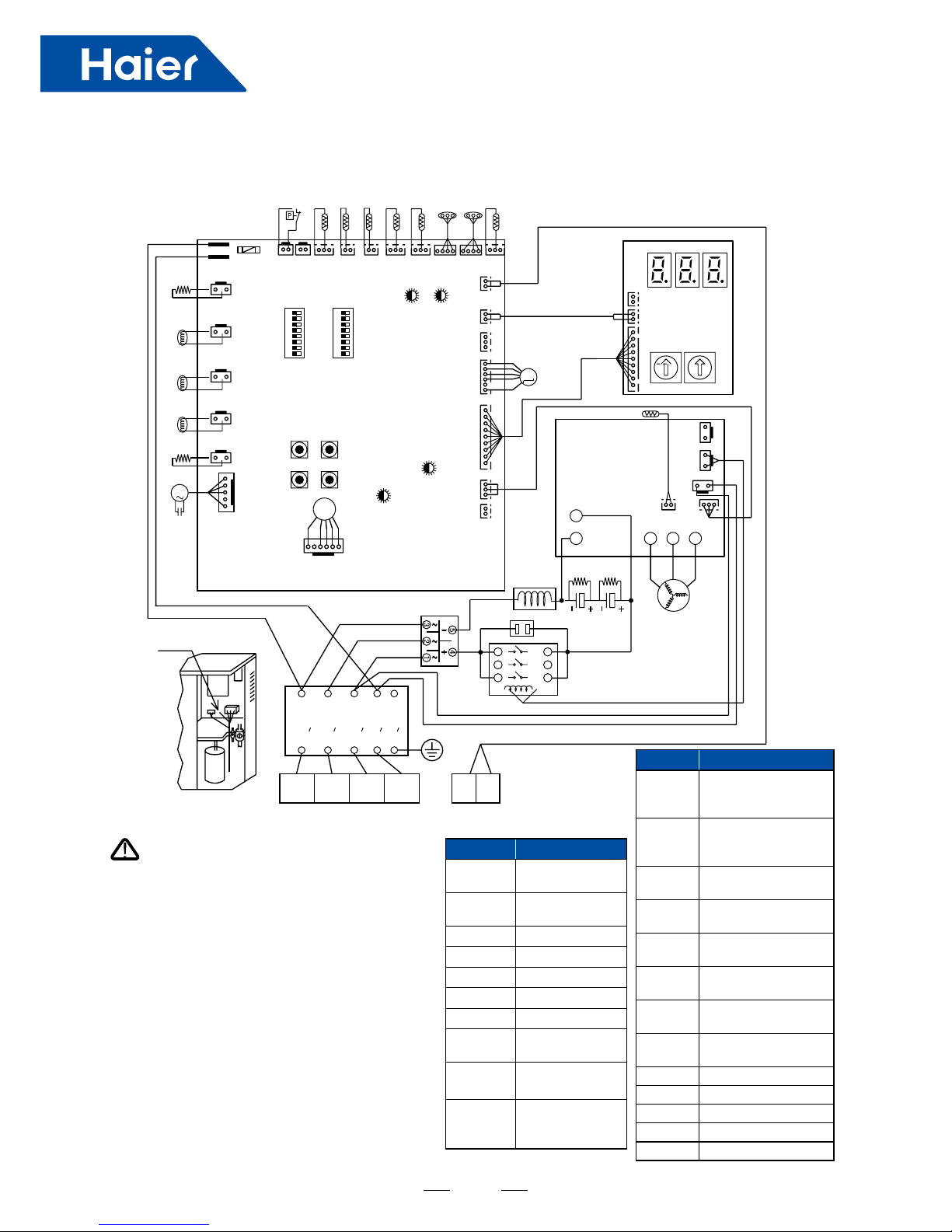
SYMBOL
Notes
Please power off rstly for about 10 minutes
before checking control box, and make sure the
voltage between P and N below 20V.
• Please check the power rstly before test, and
make sure the crankcase heater powering on for
12 hours at least to protecting compressor.The
switch BM1-1 is used for locking the indoor units
number, the initial situation is "OFF". After power on,
the display board will display【U**】,"**"indicates
the number of indoor units that the outdoor unit
can communicate with. If it can match the actual
number of indoor units, please change "OFF" to
"ON", or else x the communication problem rstly.
Forbid connecting the power wire to the "P" and "Q",
otherwise the control board will be damaged.Please
make sure the earth wire connecting the grounding
hole on the electric box rmly.
Symbol Signication
HEATER,
2
Crankcase
heater
SV1
Unloading
valve
SV2 Spray valve
4WV 4-way valve
CA Capacitor
ACFAN2 AC fan motor
DCFAN1 DC fan motor
HPS
High pressure
switch
Td
Discharging
temp. sensor
Te1, 2
Defrost
temperature
sensor
Symbol
Signication
Ts
Suction
temperature
sensor
Ta
Ambient
temperature
sensor
Pd
High pressure
sensor
Ps
Low pressure
sensor
Toil
Oil temperature
sensor
EEV
Electronic
expansion valve
Tn
IPM temperature
sensor
CB1, 2
Electrolytic
capacitor
R Red
W White
BL Blue
B Black
Y Yellow
5. Wiring Diagram
L1 L2 L3 N E
L1 L2 L3 N E
~
~
~
T1
T2
T3
L1
L2
L3
L1 L2 L3 N
PQ
M
M
1 2 3 4 5 6 7 8
1 2 3 4 5 6 7 8
M
HPS Td Te1 Te2 Ts Ta Ps Pd Toil
6.3A 250VAC
FUSE1
CN1 CN2 CN3 CN4 CN5 CN6 CN7 CN29 CN28 CN30
CN26
CN18
CN17
CN16
CN25
ACFAN2
HEATER2
SV2
SV1
4WV
HEATER
CA
CONTROL BOARD
SW1
LED1
DCFAN1
LED3
LED4 LED2
SW2
SW3
SW4
BM1 BM2
ON
ON
CN21
CN9
CN20
CN8
CN24
CN10
CN11
0150513195
LD1 LD2 LD3
CN32
CN31
CN30
LED
DISPLAY
SW01 SW02
INV Board
Tn
CN7 CN8
CN2
CN3
CN1
U V W
P
N
EEV
R W B
B
BB
B
B
W
W
W
W
W
PTC
CB1 CB2
Y
Y
R1 R2
REACTOR
R
COMP
AC Contactor
Earth Wire
Noise Filter
R W BL B
WARNING
1515
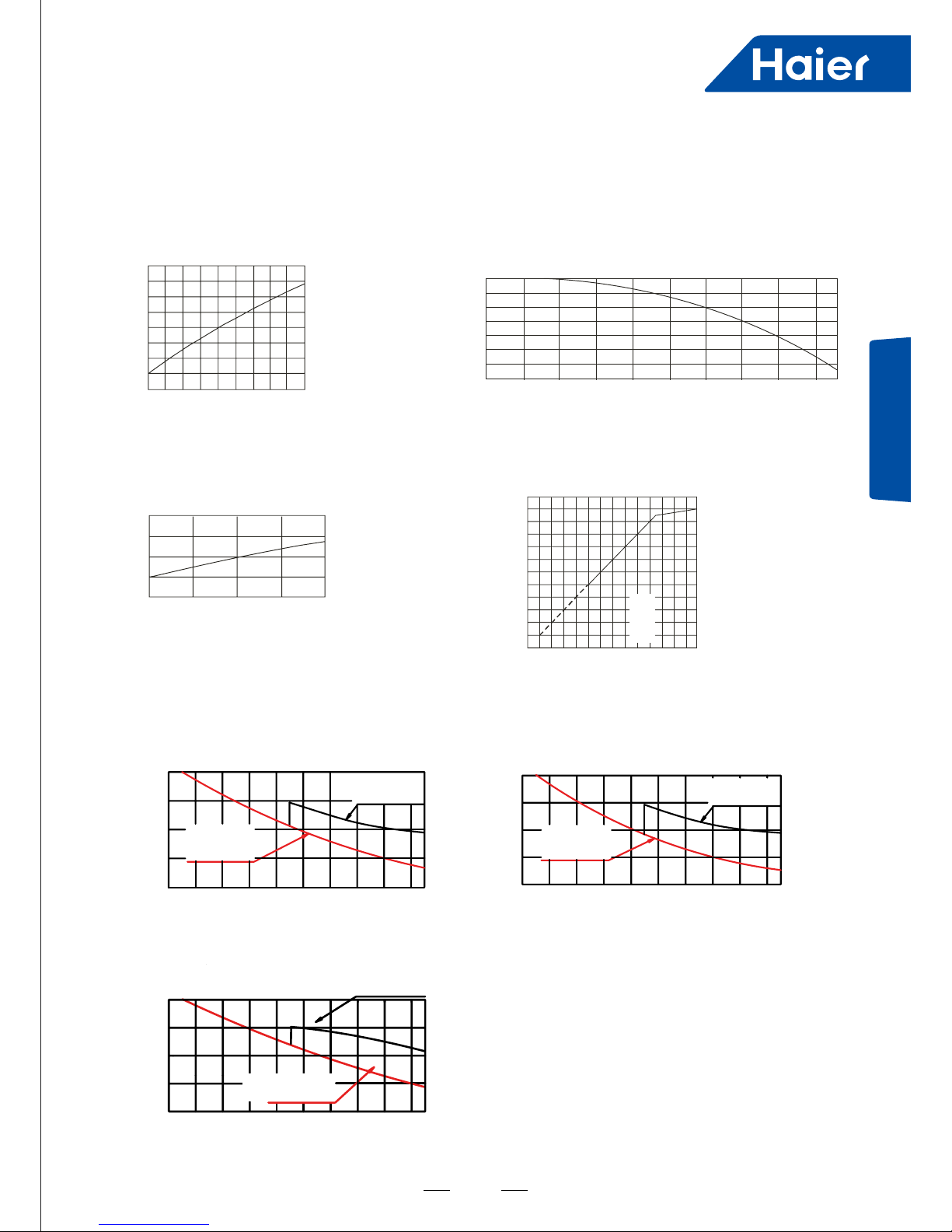
Performance Curves
(1) Calculation methed of refrigerating capacity----refrigerating capacity to be known=refrigerating
capacity*(A*B*C*D*E)W
E. Fall of refrigerant pipe of indoor and outdoor unit, capacity compensation value of pipe length
C. Capacity modication value under airow variation
rate of indoor unit group (only fro duct unit)
A. Capacity compensation value of indoor
air wet-bulb temperature condition
B. Capacity compensation value of outdoor
air dry-bulb temperature condition
D. Capacity compensation suitable for
total capability of indoor unit group
6. Performance Curves
1.2
1.1
1.0
0.9
0.8
15 20 24
Indoor air dry-bulb temperature (°C )
Capacity modication value
1.2
1.1
1.0
0.9
Outdoor air wet-bulb temperature (°C )
Capacity modication value
-5 200 255 3010 3515 40 43
1.1
1.0
0.9
80 90 100 110 120
Airow variation rate (%)
Capacity modication value
120
100
100 120 130
80
60
40
20
20
40 60 80
0
Total capacity of indoor unit group (%)
Standard
capacity
liquid pipe
: φ12.7
gasp ipe
:φ31.8
Single-way pipe length m
)
AV12NMSETA
)
Capacity modication value
1.00
0.95
0.90
0.85
0.80
100
120
140
160
180
20
40 60 80
0
Liquid pipe: φ12.7
Gas pipe : φ25.4
Liquid pipe: φ15.88
Gas pipe : φ28.58
Single-way pipe length (m)
AV12NMSETA
Capacity modication value
1.00
0.95
0.90
0.85
0.80
100
120
140
160
180
20
40 60 80
0
Liquid pipe: φ12.7
Gas pipe : φ22.22
Liquid pipe: φ9.52
Gas pipe : φ19.05
Single-way pipe length (m)
AV08NMSETA
Liquid pipe: φ12.7
Gas pipe : φ25.4
Liquid pipe: φ9.52
Gas pipe : φ22.22
Capacity modication value
1.00
0.95
0.90
0.85
0.80
100
120
140
160
180
20
40 60 80
0
Single-way pipe length (m)
AV10NMSETA
1616
Notes:
• The refrigerant pipe should be thickened when the single way length is over 90m.
• When in cooling mode, outdoor is lower than indoor; or when in heating mode, outdoor is higher than indoor, the
compensation factor should be decreased the below value from the above gure.
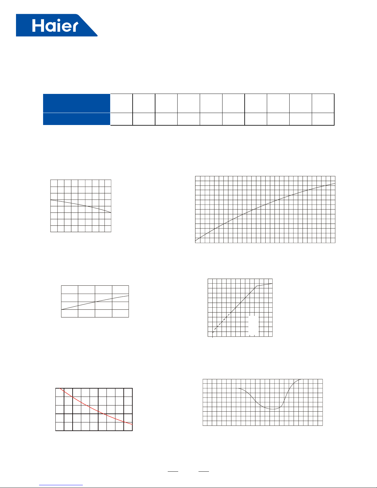
(2) Calculation method of refrigerating capacity----heating capacity to be known=refrigerating
capacity*(A*B*C*D*E*F)W
Vertical height drop
between indoor and
outdoor
5m 10m 15m 20m 25m 30m 35m 40m 45m 50m
Adjustment factor 0.003 0.006 0.009 0.012 0.015 0.018 0.021 0.024 0.027 0.030
A. Capacity compensation value of indoor
air dry-bulb temperature condition
C. Capacity modication value under airow variation
rate of indoor unit group (only fro duct unit)
B. Capacity compensation value of outdoor air
wet-bulb temperature condition
D. Capacity compensation suitable for
total capability of indoor unit group
E. Capacity compensation value of pipe
length between outdoors
F. Capacity compensation value for defrost
capability of outdoor heat exchanger
1.2
1.2
1.1
1.0
0.9
0.8
15 20 24
Indoor air dry-bulb temperature (℃)
1.1
1.0
0.7
0.9
0.6
0.8
0.5
-15 -10 -5 0
Outdoor air wet-bulb temperature (℃)
5
10 15
1.1
1.0
0.9
80 90 100 110 120
Airow variation rate (%)
Capacity modication value
120
100
100 120 140
80
60
40
20
20
40 60 80
0
Total capacity of indoor unit group (%)
Standard
capacity
Capacity modication value
Capacity compensation value
All the modules in the same
Single-way pipe length (m)
1.00
0.98
0.96
0.94
0.92
0.90
0
20 40 60 80 100 120
140
160
180
Capacity compensation value
Outdoor air wet-bulb temperature (℃)
1.0
0.9
0.8
-15 -10 -5 0 5 10
1717
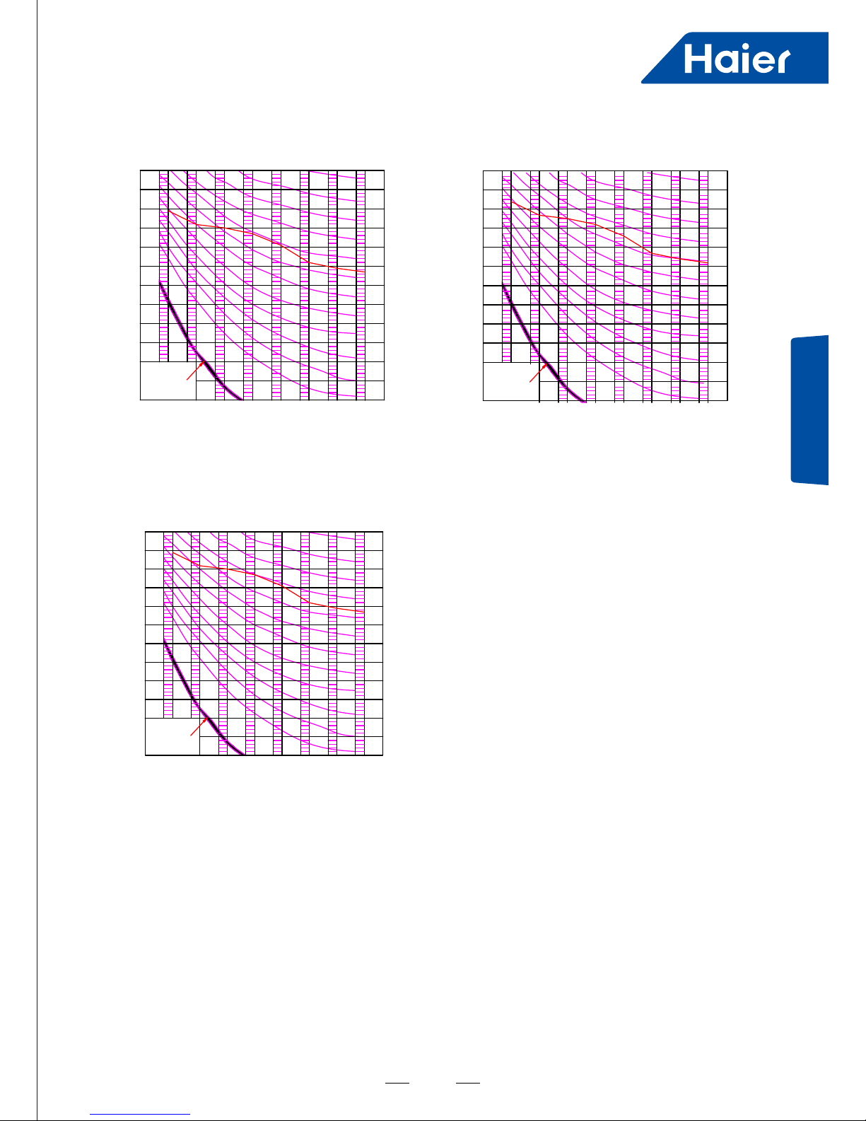
Noise Level
7. Noise Level
AV08NMSETA
H
Octave band sound pressure level dB (A
)
Limit of
audible
continuous
noise
70
60
50
40
30
20
10
63 125 250 500 1000 2000 4000 8000
NC-20
NC-30
NC-40
NC-50
NC-60
Octave band center frequency Hz
AV10NMSETA
Octave band sound pressure level dB (A
)
Limit of
audible
continuous
noise
70
60
50
40
30
20
10
63 125 250 500 1000 2000 4000 8000
NC-20
NC-30
NC-40
NC-50
NC-60
Octave band center frequency Hz
H
AV12NMSETA
Octave band sound pressure level dB (A
)
Limit of
audible
continuous
noise
70
60
50
40
30
20
10
63 125 250 500 1000 2000 4000 8000
NC-20
NC-30
NC-40
NC-50
NC-60
Octave band center frequency Hz
H

1818
8. Outdoor Installation
■ This manual should always be accessible and close to this air condition equipment.
■ There are two types of indications, "WARNING" and "CAUTION". The indication preventing from death
or heavy injury is listed as "WARNING". Even the indication listed as "CAUTION " may also cause serious
accident. Both of them are related to safety, and should be strictly followed.
■ After installation and start-up commissioning, please handover the manual to the user. The manual should be
well kept in safe place and close to the unit.
■ The installation or the maintenance should be performed by an authorized agency. The wrong operation of this air
condition equipment may cause water leakage, electric shock or re.
■ Please install the unit on the top of a solid foundation or structure which is strong enough to support the unit.
■ The installation of this air condition equipment should follow local construction codes.
■ Use the right cable size, secure the terminal rmly, organize the cables well and make sure no tension is added
on cables. Cable insulation should not be damaged. The incorrect installation may lead to overheat or re.
■ When installing or moving the unit, the refrigerant system should be vacuumed and recharged with R410A
refrigerant. If any other gas enters the system, it may lead to abnormal high pressure which may cause damage
or injury.
■
Please use the proper manifolds or branches during the system installation. The wrong parts may cause
refrigerant leakage.
■ Keep the drain pipe away from toxic gas vents to prevent possible pollution of indoor environment.
■ During or after the installation, please check whether there is refrigerant leakage. If any leakage, please take
any measures for ventilation. The refrigerant may be toxic at some concentration levels.
■ The unit is not explosion-proof. Please keep it away from ammable gases.
■ The drain pipe should be installed per this manual to ensure proper drainage. The pipe should be well insulated
to avoid condensation. Wrong installation may lead to water leakage.
Both liquid pipe and the gas pipe should be also well insulated. Not enough insulation may lead to system
performance deterioration or humidity formation.
■ This air condition equipment is not intended to be operated by persons with lack of experience and training,
unless they have supervision or instruction concerning use of this air condition equipment.
■ Please keep children away from this air condition equipment.
WARNING
1919
Outdoor Installation
■ Grounding wire should be connected with the grounding bar. The grounding wire can not be connected to the gas
pipe, water pipe, lightening rod or the telephone grounding wire. Improper grounding may cause
electric shock.
■ Units installed on roof should have appropriate access and handrail.
■ Use the wrench to fasten the nut and are at proper torque. Excessive torque may cause ared section to broke
leading to refrigerant leakage.
■ After refrigerant pipe installation, please take nitrogen leakage test to avoid refrigerant leakage.
■ R410A is the only permitted refrigerant.
■ To avoid mischarging wrong refrigerant, the check valve diameter is changed for R410A. To strengthen the pipe,
the ared pipe dimension is also changed. Please use R410A specied tools as shown below.
R410A specied tools Remarks
1
Gauge manifold Range: HP >4.5MPa, LP >2MPa
2
Charge hose Pressure: HP:5.3MPa, LP:3.5MPa
3
Electronic weight for charging R410A No other means permitted
4
Torque wrench
5
Flare tool
6
Copper pipe gauge for adjusting projecting margin
7
Vacuum pump tting Vacuum pump must be equipped with check valve
8
Leakage detector Only Helium detector permitted
When charging refrigerant, the refrigerant must be in liquid state from the tank.
■ To prevent EMC interference on other appliances, please keep indoor unit, outdoor unit, power cable and
connecting wire at least 1m away from those appliances .
■ Fluorescent lamp (reverse phase or rapid start type) may interfere the remote controller's signal. Please install
indoor unit away from uorescent lamp. The farther the better.
For installation, please review the items below:
■ Is the connected units quantity and the total capacity in the allowable range?
■ Is the refrigerant pipe length in the limited range?
■ Is the pipe size proper? And if the pipe installed horizontally?
■ Is the branch pipe installed horizontally or vertically?
■ Is the additional refrigerant counted correctly and weighed by the standard balance?
■ Is there refrigerant leakage?
■ Is all the indoor power supplies can be on/off simultaneously?
■ Is the power voltage in compliance with the data marked on the rating label?
■ Is the address of indoors has been set?
CAUTION
2020
(1) Before installation
1) Before installation, check if the model, power supply, pipe, wires and parts purchased respectively are correct.
2) Check if the indoors and outdoors can be combined as the following.
Outdoor Indoor
Capacity (X 100W) Indoor Qty Total indoor capacity (X 100W)
AV08NMSETA 13 113~293
AV10NMSETA 16 140~364
AV12NMSETA 16 167~436
Air-conditioner can't be installed in the place with inammable gas. Or it will cause re
hazard.
The unit should be installed at the place where the cold/hot air or noise will not interfere
the neighbours.
The unit should be installed at the place with good ventilation. No obstacle at the air
inlet/outlet. And no strong wind blows the unit.
The installation space refers to the latter info.
The unit should be installed at the strong enough place. Or it will cause vibration and
noise.
The place where the water can ow uently.
The place where no other heat source will affect the unit.
Pay attention to the snow against clogging the outdoor.
In installation, install the anti-vibration rubber between the unit and the bracket.
The unit is better not be installed at the below places, or it will cause damage.
The place where there is corrosive gas (spa area etc).
The place blowing salty air (seaside etc).
Exists the strong coal smoke.
The place with high humidity.
The place where there is device emitting Hertzian waves.
The place where voltage changes greatly.
(2) Installation place selection
2121
Outdoor Installation
(3) Transportation and hoisting
Hoisting
■ Please remove the outdoor unit to the installation location as far as possible near place befor open the packaging.
■ Forbid on the equipments to place anything, need to use 2 ropes while promoting outdoor.
■ Please according to following way hoisting outdoor:
■ Ensure that the outdoor unit when hosting the level to rise slowly.
■ Do not remove the packaging.
■ When hoisting do not have to tie up the elevator to the unit hits on the packaging and the outside wrapping.
■ When hoisting exterior must use the suitable protection.
Handling
Before the installation, outdoor do not deposit any material, otherwise likely has the re or the accident.
When handling unit, please operate as shown in the following gure and note the following points
1. Forbids to demolish the wooden foundation.
2. Prevent the outdoor to incline.
3. Should be handling more than two.
Handle 2
Handle 1
Handle 3
Handle 4
2222
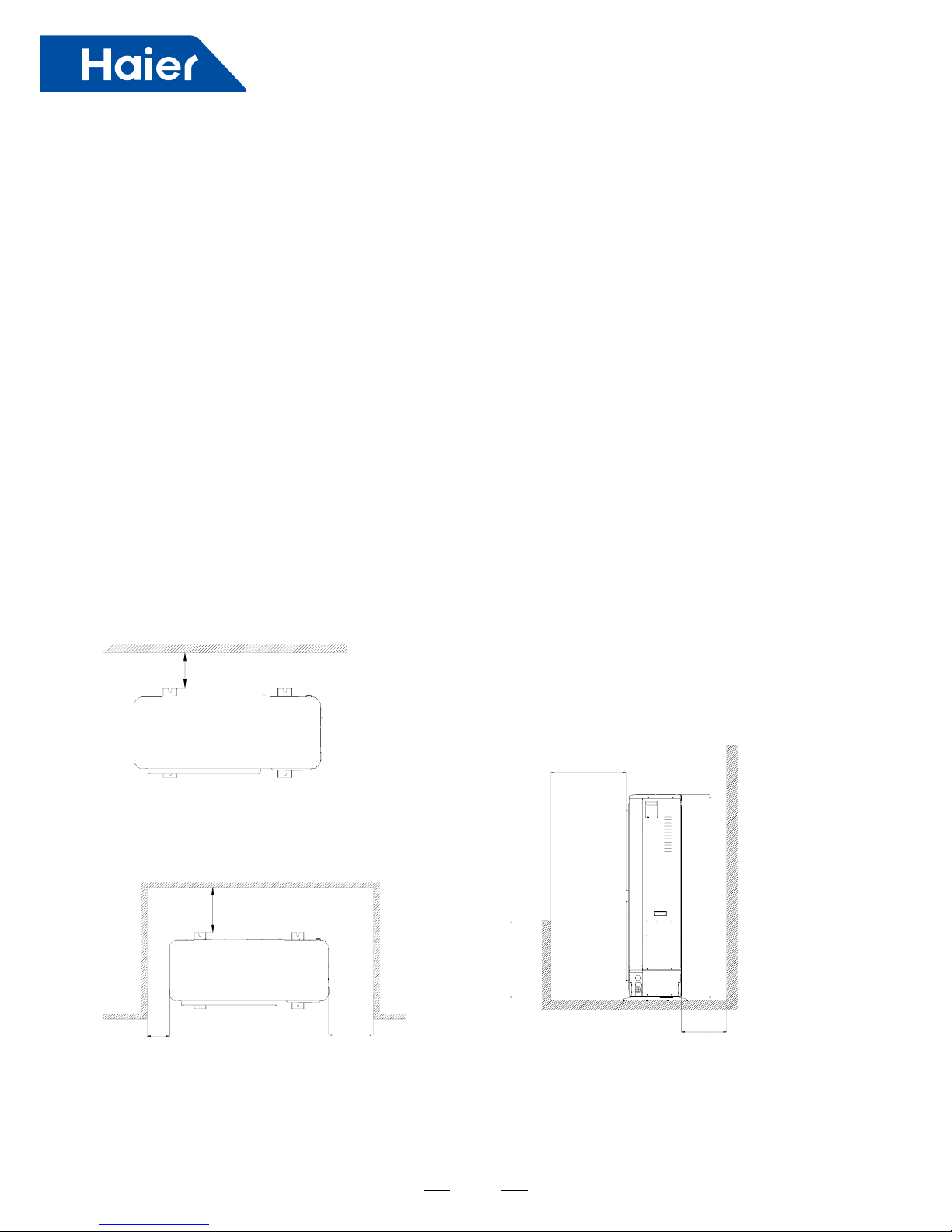
Single installation around the opening
Inlet
Outlet
Min200mm
Single installation around the closed
Inlet
Outlet
Min300mm
Min300mmMin150mm
Min360mm
Outdoor installation
Installation location
■ Outdoor unit should be placed in well ventilated and dry place.
■ Outdoor noise and exhaust should not affect neighbors and around the ventilation.
■ Ensure the ground steadily reliable.
■ Do not install the outdoor unit on high oil, salt spray or harmful gases.
■ Don't being installed to electromagnetic wave can directly radiate an electricity box and keep off electromagnetic
wave radiation possibly, at least more than 3 meters.
■ When ice snow overlay area installs outdoor unit, please add to defend snow cover.
■ Outdoor unit installed in the shade, avoiding direct sunlight or high temperature heat sources of radiation.
■ Do not install in dusty or polluted place to prevent outdoor unit heat exchanger jam.
■ The outdoor unit should install in the public unapproachable place.
Installation and maintenance space
As shown below, install the outdoor unit should allow sufcient space for handing and maintenance.
Case 1: Stumbling block on the inlet , also upside opens.
H
A
h
Single installation around the opening
Single installation around the closed
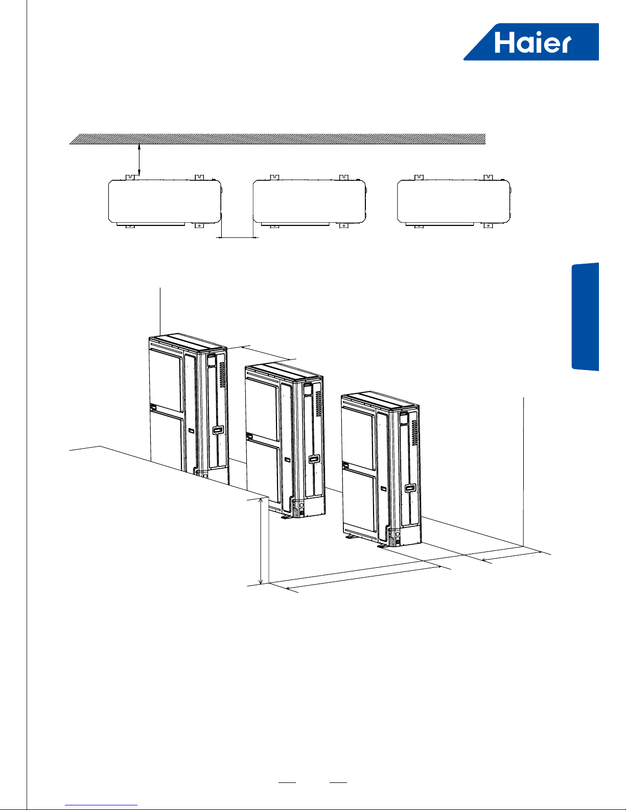
2323
Outdoor Installation
Multi Outdoor
Min300mm
Min300mm
Min360mm
Min300mm
Inlet
Outlet
h
A
2424
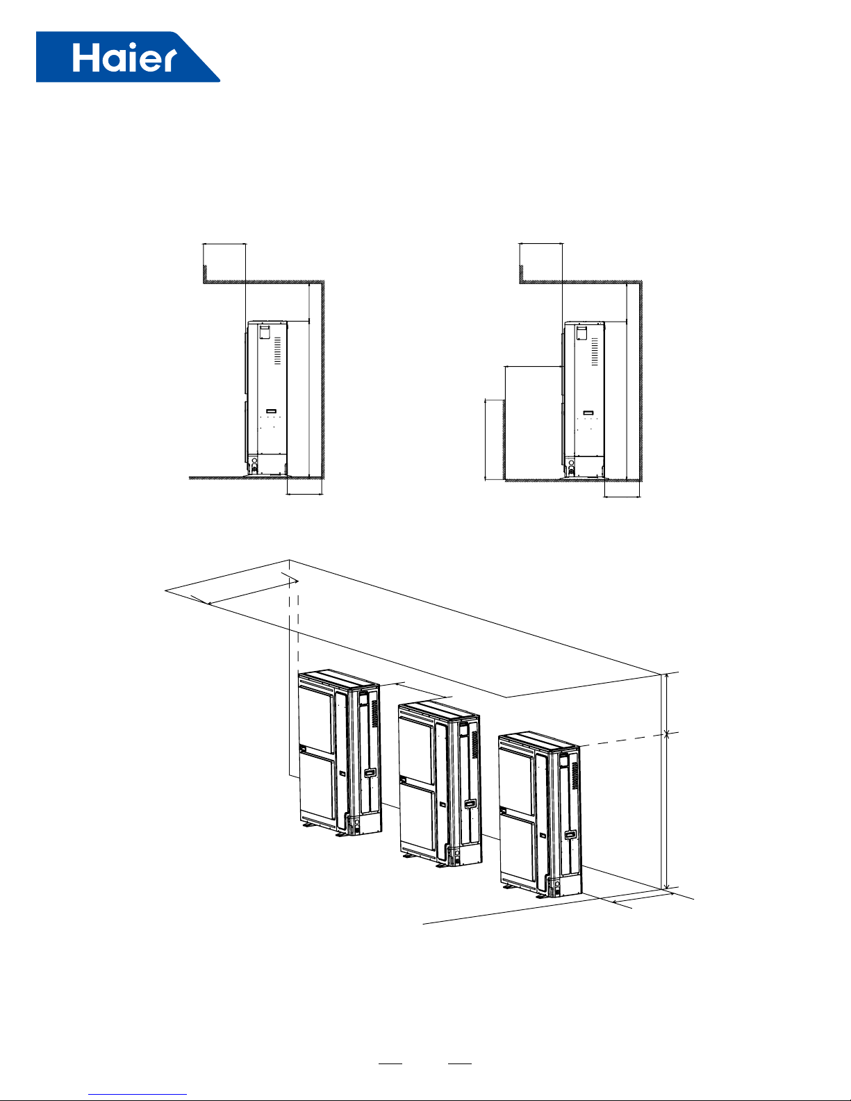
Case 2: Stumbling block on the inlet and top side
Single Outdoor
Multi Outdoor
Max300mm
Min360mm
Min300mm
Min500mm
H
Max300mm Max300mm
Min
500
mm
Min360mm Min360mm
L
H
H
A
Min
500
mm
2525
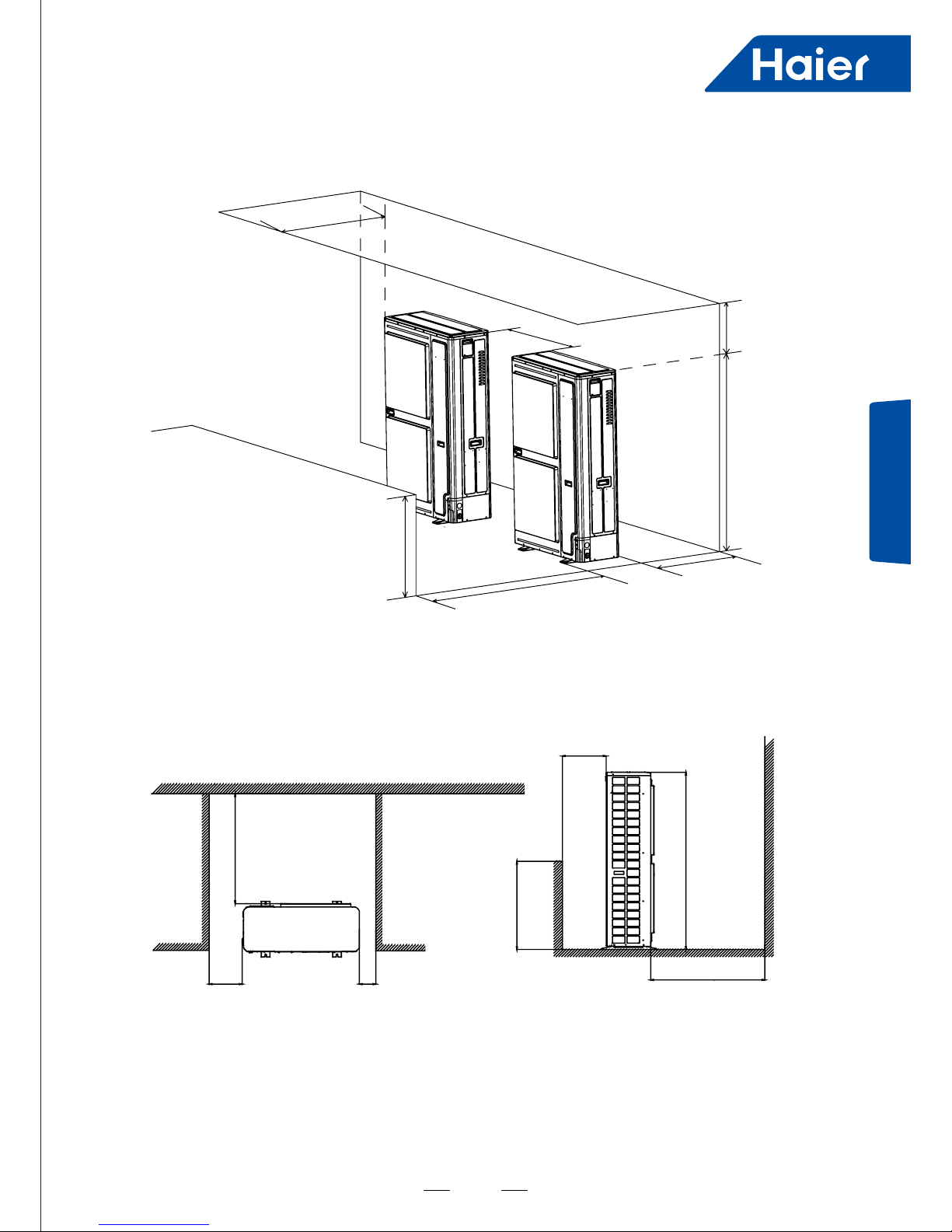
Outdoor Installation
Case 3:Stumbling block on the outlet, both right and left side
Single Outdoor
Max300mm
Min300mm
Min150mm
Min300mm
Min1000mm
Min1000mm
Min360mm
Min360mm
Min500mm
H
H
A
L
h
Not more than two sets
 Loading...