

Haier 1U28HS1ERA, 1U36HS1ERA, 1U48LS1ERA, 1U48LS1EAB, 1U48IS1EAB Installation Manual
...
INSTALLATION MANUAL
SINGLE SPLIT AIR CONDITIONER
Please read this manual carefully before installation.
Keep this operation manual for future reference.
No. 0150510322 B
1U28HS1ERA
1U36HS1ERA
1U48IS1EAB
1U60IS1ERA
1U60IS1ERB
1U60IS1EAB
AU60NAIESA
1U48LS1ERA
1U48LS1ERB
1U48LS1EAB

INSTALLATION MANUAL
SINGLE SPLIT AIR CONDITIONER
Please read this manual carefully before installation.
Keep this operation manual for future reference.
Contents
English
Safety Precautions
Read Before Installation
Name of Parts
Installation Procedure
Troubleshooting
3
7
10
11
18
1U28HS1ERA
1U36HS1ERA
1U48IS1EAB
1U60IS1ERA
1U60IS1ERB
1U60IS1EAB
AU60NAIESA
1U48LS1ERA
1U48LS1ERB
1U48LS1EAB
3
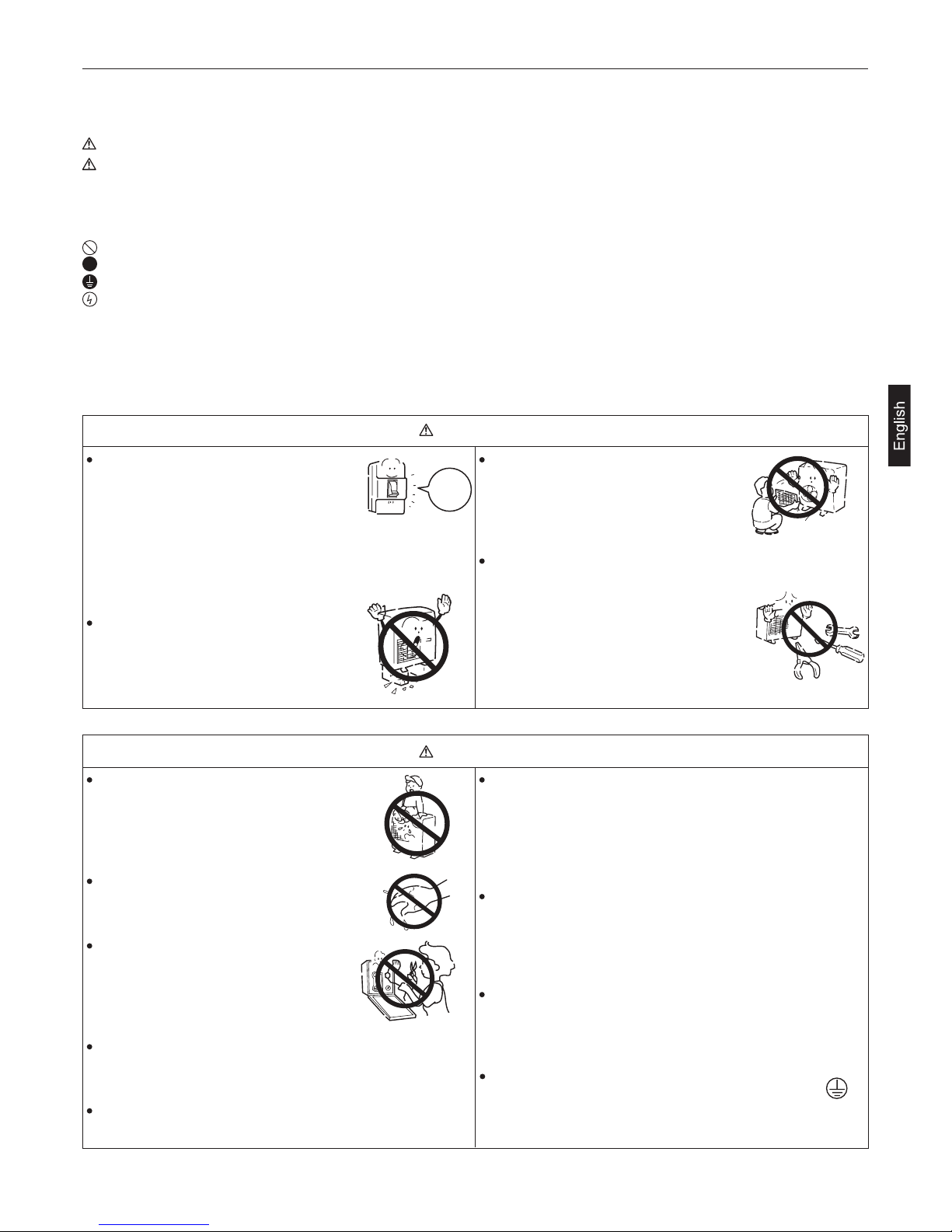
Safety Precautions
Be sure to conform with the following important Safety Precautions.
Carefully read the following information in order to operate the air conditioner correctly.
If any abnormal phenomena is found
(e. g.smell of firing), please cut off
the power supply immediately, and
contact the dealer to find out the
handling method.
In such case, to continue using the conditioner will damage
the conditioner, and may cause electrical shock or fire
hazard.
Don't dismantle the outlet of the
outdoor unit.
The exposure of fan is very dangerous
which may harm human beings.
Symbols used in the illustrations
:Indicates an action that must be avoided.
:Indicates that important instructions must be followed.
:Indicates a part which must be grounded.
:Beware of electric shock (This symbol is displayed on the main unit label.)
After reading this handbook, hand it over to those who will be using the unit.
The user of the unit should keep this mamual at hand and make it available to those who will be performing repairs or
relocating the unit. Also, make it available to the new user when the user changes hands.
Below are listed three kinds of Safety Precautions and Suggestions.
Incorrect operations may result in severe consequences of death or serious injuries.
Incorrect operations may result in injuries or machine damages; in some cases may
cause serious consequences.
INSTRUCTIONS:
These information can ensure the correct operation of the machine.
After a long time use of air-conditioner
the base should be checked for any
damages.
If the damaged base is not repaired, the
unit may fall down and cause accidents.
When need maintenance and repairment,
call dealer to handle it.
Incorrect maintenance and repairment
may cause water leak, electrical shock
and fire hazard.
Air-conditioner can't be installed in the environment with
inflammable gases because the inflammable gases near
air-conditioner may cause fire hazard.
Please let the dealer be responsible for installing the
conditioner. Incorrect installation may cause water leak,
electrical shock and fire hazard.
Connect earthing wire.
Earthing wire should not be connected to the gas
pipe, water pipe, lightning rod or phone line,
incorrect earthing may cause shock.
Use discharge pipe correctly to ensure efficient discharge.
Incorrect pipe use may cause water leaking.
Installed electrical-leaking circuit breaker.
It easily cause electrical shock without circuit breaker.
Call the dealer to take measures to prevent the refrigerant
from leaking.
If conditioner is installed in a small room, be sure to take
every measure in order to prevent suffocation accident
even in case of refrigerant leakage.
When conditioner is installed or reinstalled, the dealer should
be responsible for them.
Incorrect installation may cause water leaking, electrical
shock and fire hazard.
No goods or nobody is permitted to
placed on or stand on outdoor unit.The
falling of goods and people may cause
accidents.
Don't operate the air-conditioner with
damp hands.Otherwise it will be shocked.
Only use correctly-typed fuse.
May not use wire or any other materials
replacing fuse, otherwise it may cause
faults or fire accidents.
Earthing
switch off
!
WARNING
CAUTION
WARNING
WARNING
4
Safety Precautions
Have the unit professionally installed.
Improper installation by an unqualified person may result
in water leak, electric shock, or fire.
Be sure to carefully follow each step in this handbook when
installing the unit.
Improper installation may result in water leak, electric shock,
smoke or fire.
Have all electrical work performed by a licensed electrician
according to the local regulations and the instructions given
in this manual. Secure a circuit designated exclusively to
the unit.
Improper installation or a lack of circuit capacity may cause
the unit to malfunction or present a risk of electric shock,
smoke,and fire.
Place the unit on a stable, level surface that withstands the
weight of the unit to prevent the unit from tipping over or
falling causing injury as a result.
Only use specified cables for wiring. Securely connect each
cable, and make sure that the cables are not straining the
terminals.
Cables not connected securely and properly may generate
heat and cause fire.
Take necessary safety measures against typhoons and
earthquakes to prevent the unit from falling over.
Do not make any changes or modifications to the unit. In
case of problems, consult the dealer.
If repairs are not made properly, the unit may leak water
and present a risk of electric shock, or it may produce smoke
or cause fire.
Securely attach the terminal cover(panel) on the unit.
If installed improperly, dust and/or water may enter the unit
and present a risk of electric shock, smoke or fire.
Only use refrigerant R410A as indicated on the unit when
installing or relocating the unit.
The use of any other refrigerant or an introduction of air into
the unit circuit may cause the unit to run an abnormal cycle
and abnormal cycle and cause the unit to burst.
In the event of a refrigerant gas leak, provide adequate
ventilation to the room.
If leaked refrigerant gas is exposed to a heat source, noxious
gases may form.
Do not touch the fins on the heat exchanger with bare hands,
for they are sharp and dangerous.
Do not try to defeat the safety features of the devices, and
do not change the settings.
Defeating the safety features on the unit such as the pressure
switch and temperature switch or using parts other than the
dealer or specialist may result in fire or explosion.
When installing the unit in a small room, safeguard against
hypoxia that results from leaked refrigerant reaching the
threshold level.
Consult the dealer for necessary measures to take.
When relocating the air conditioner, consult the dealer or
a specialist.
Improper installation may result in water leak, electric shock,
or fire.
After completing the service work, check for a refrigerant
gas leak.
If leaked gas refrigerant is exposed to a heat source such
as fan heater,stove,and electric grill, noxious gases may
form.
Only use specified parts.
Have the unit professionally installed. Improper installation
may cause water leak, electric shock,smoke, or fire.
With All-Fresh type air conditioners, outdoor air may be
directly blown into the room upon thermo off. Take this into
consideration when installing the unit.
Direct exposure to outdoor air may present a health hazard,
and it may also cause food items to deteriorate.
Children should be supervised to ensure that they do not
play with the appliance.
WARNING
WARNING
This appliance is not intended for use by persons (including
children) with reducedphysical, sensory or mental capabilities,
or lack of experience and knowledge, unless they have been
given supervision or instruction concerning use of the
appliance by a person responsible for their safety.
5
Safety Precautions
Precautions for Handling Units for Use with R410A
Do not use the existing refrigerant piping
The old refrigerant and refrigerator oil in the existing piping
contain a large amount of chlorine, which will cause the
refrigerator oil in the new unit to deteriorate.
R410A is a high-pressure refrigerant, and the use of the
existing piping may result in bursting.
Keep the inner and outer surfaces of the pipes clean and
free of contaminants such as sulfur, oxides, dust/dirt shaving
particles,oils,and moisture.
Contaminants inside the refrigerant piping will cause the
refrigerant oil to deteriorate.
Use a vacuum pump with a reverse-flow check valve.
If other types of valves are used, the vacuum pump oil will
flow back into the refrigerant cycle and cause the refrigerator
oil to deteriorate.
Do not use the following tools that have been used with the
conventional refrigerants. Prepare tools that are for exclusive
use with R410A.
(Gauge manifold, charging hose, gas leak detector,
reverse-flow check valve, refrigerant charge base,vacuum
gauge, and refrigerant recovery equipment.)
If refrigerant and/or refrigerant oil left on these tools are
mixed in with R410, or if water is mixed with R410A, it will
cause the refrigerant to deteriorate.
Since R410A does not contain chlorine, gas-leak detectors
for conventional refrigerators will not work.
Store the piping to be used during installation indoors, and
keep both ends of the piping sealed until immediately before
brazing.(keep elbows and other joints wrapped in plastic.)
If dust, dirt, or water enters the refrigerant cycle, it may
cause the oil in the unit to deteriorate or may cause the
compressor to malfunction.
A large amount of mineral oil will cause the refrigerating
machine oil to deteriorate.
Use a small amount of ester oil, ether oil, or alkylbenzene
to coat flares and flange connections.
Use liquid refrigerant to charge the system.
Charge the unit with gas refrigerant will cause the refrigerant
in the cylinder to change its composition and will lead to
a drop in performance
Do not use a charging cylinder.
The use of charging cylinder will change the composition
of the refrigerant and lead to power loss.
Exercise special care when handling the tools.
An introduction of foreign objects such as dust, dirt or
water into the refrigerant cycle will cause the refrigerating
machine oil to deteriorate.
Only use R410A refrigerant.
The use of refrigerants containing chlorine(i.e. R22) will
cause the refrigerant to deteriorate.
Before Installing the Unit
Do not install the unit in a place where there is a possibility
of flammable gas leak.
Leaked gas accumulated around the unit may start a fire.
Do not use the unit to preserve food, animals, plants, artifacts,
or for other special purposes.
The unit is not designed to provide adepuate conditions
to preserve the quality of these items.
Do not use the unit in an unusual environment
The use of the unit in the presence of a large amount of
oil, steam, acid, alkaline solvents or special types of sprays
may lead to a remarkable drop in performance and/or
malfunction and presents a risk of electric shock, smoke,
or fire.
The presence of organic solvents, corroded gas (such as
ammonia,sulfur compounds,and acid may cause gas or
water leak.)
When installing the unit in a hospital, take necessary measures
against noise.
High-frequency medical equipment may interfere with the
normal operation of the air conditioning unit or the air
conditioning unit may interfere with the normal operation
of the medical equipment
When humidity level exceeds 80% or when the drainage
system is clogged, indoor units may drip water.
Installation of a centralized drainage system for the outdoor
unit may also need to be considered to prevent water drips
from the outdoor units.
Do not place the unit on or over things that may not get wet.
Caution
Caution
Caution
6
Safety Precautions
Before Installing (Relocating) the Unit or Performing Electric Work
Ground the unit.
Do not connect the grounding on the unit to gas pipes,water
pipes, lightning rods, or the grounding terminals of
telephones. Improper grounding presents a risk of electric
shock, smoke, fire, or the noise caused by improper
grounding may cause the unit to malfunction.
Before the Test Run
Do not operate switches with wet hands to avoid electric.
Allow for at least five minutes before turning off the unit,
otherwise the unit may leak water or experience other
problems.
Do not turn off the power immediately after stopping the unit.
If the wires are too taut, they may break or generate heat
and/or smoke and cause fire.
Make sure the wires are not subject to tension.
Install a breaker for current leakage at the power source
to avoid the risk of electric shock.
Without a breaker for current leakage, there is a risk of
electric shock, smoke or fire.
Use breakers and fuses (electrical current breaker, remote
switch<switch+Type-B fuse>,molded case circuit breaker)
with a proper current capacity.
The use of large-capacity fuses, steel wire, or copper wire
may damage the unit or cause smoke or fire.
When installing draining pipes, follow the instructions in the
manual, and make sure that they properly drain water so as
to avoid dew condensation.
If not installed properly, they may cause water leaks and
damage the furnishings.
Do not spray water on the air conditioners or immerse the
air conditioners in water.
Water on the unit presents a risk of electric shock.
Periodically check the platform on which is placed for damage
to prevent the unit from falling.
If the unit is left on a damaged plarform, it may topple over,
causing injury.
Things such as nails may be included in the package.
Dispose of them properly to prevent injury.
Plastic bags present a choking hazard to children. Tear
up the plastic bags before disposing of them to prevent
accidents.
Properly dispose of the packing materials.
Do not touch the refrigerant pipes with bare hands during
and immediately after operation.
Depending on the state of the refrigerant in the system,
certain parts of the unit such as the pipes and compressor
may become very cold or hot and may subject the person
to frost bites or burning.
Do not operated the unit without panels and safety guards
in their proper places.
They are there to keep the users from injury from
accidentally touching rotating, high-tempreture or highvoltage parts.
Dust particles in the air may clog the system and cause
malfunction.
Do not operate the unit without air filters.
Caution
Caution
7
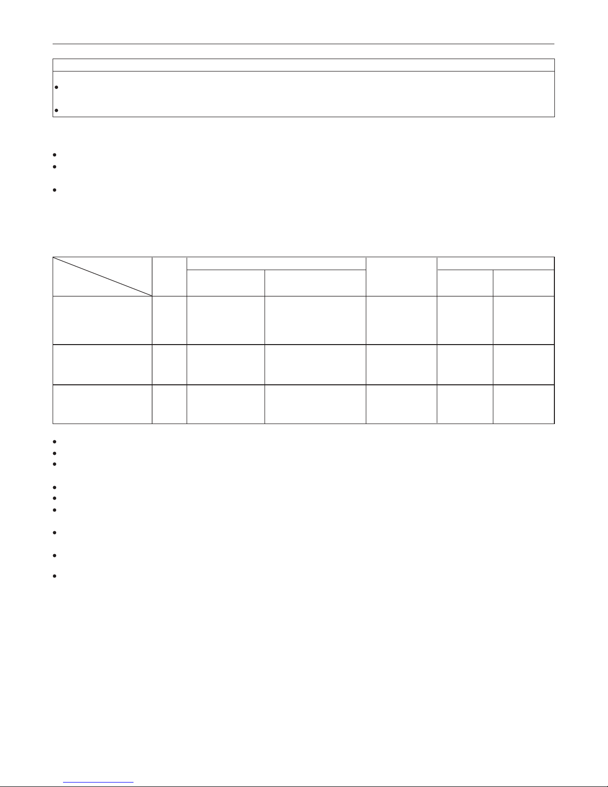
Read Before Installation
Tools/Materials Use Notes
Gauge Manifold Evacuating,refrigerant charging 5.09MPa on the High-pressure side.
Charging Hose Evacuating, refrigerant charging Hose diameter larger than the concentional ones.
Refrigerant Recovery Equipment Refrigerant recovery
Refrigerant Cylinder Refrigerant charging Write down the refrigerant type. Pink in color at the top of the cylinder.
Refrigerant Cylinder Charging Port Refrigerant charging Hose diameter larger than the conventional ones.
Flare Nut Connecting the unit to piping Use Type-2 Flare nuts.
Tools/Materials Use Notes
Gas leak detector Detection of gas leaks The ones for HFC type refrigerant may be used.
Vacuum Pump Vacuum drying May be used if a reverse flow check adaptor is attached.
Refrigerant Recovery Equipment Recovery of refrigerant May be used if designed for use with R410A.
Flare Tool Flare machining of piping Chages have been made in the flare machining dimension.Refer to the next page.
Tools/Materials Use Notes
Vacuum Pump with a Check Valve Vacuum drying
Bender Bending pipes
Pipe Cutter Cutting pipes
Torque Wrench Tightening flare nuts Only 12.70 (1/2'') and 15.88(5/8'') have a larger flare machining dimension.
Welder and Nitrogen Cylinder Welding pipes
Refrigerant Charging Meter Refrigerant charging
Vacuum Gauze Checking vacuum degree
Tools/Materials Use Notes
Charging Cylinder Refrigerant Charging Must not be used with R410-type units.
CAUTION
Items to Be Checked
(1). Verify the type of refrigerant used by the unit to be serviced. Refrigerant Type: R410A
(2). Check the symptom exhibited by the unit to be serviced. Look in this service handbook for symptoms relating to the
refrigerant cycle.
(3). Be sure to carefully read the safety precautions at the beginning of this document.
(4). If there is a gas leak or if the remaining refrigerant is exposed to an open flame, a noxious gas hydrofluoric acid may
form. Keep workplace well ventilated.
Install new pipes immediately after removing old ones to keep moisture out of the refrigerant circuit.
Chloride in some types of refrigerants such as R22 will cause the refrigerating machine oil to deteriorate.
Necessary Tools and Materials
Prepare the following tools and materials necessary for installing and servicing the unit.
Necessary tools for use with R410A(Adaptability of tools that are for use with R22 and R407C).
1. To be used exclusively with R410A ( Not to be used if used with R22 or R407C )
2. Tools and materials that may be used with R410 with some restrictions
3. Tools and materials that are used with R22 or R407C that can also be used with R410A
4. Tool and materials that must not used with R410A
Tools for R410A must be handled with special care, and keep moisture and dust from entering the cycle.
8
Read Before Installation
Maximum Operation Pressure Applicable Refrigerants
3.4MPa R22, R407C
4.15MPa R410A
Use pipes that meet the local standards.
Use pipes made of phosphorus deoxidized copper.
Since the operation pressure of the units that use R410A is higher than that of the units for use with R22, use pipes with
at least the radial thickness specified in the chart below. (Pipes with a radial thickness of 0.7mm or less may not be used.)
Although it was possible to use type-O for pipes with a size of up to
19.05(3/4") with conventional refrigerants, use type1/2H pipes for units that use R410A.(Type-O pipes may be used if the pipe size is 19.05 and the radial thickness is 1.2t.)
The table shows the standards in Japan. Using this table as a reference, choose pipes that meet the local standards.
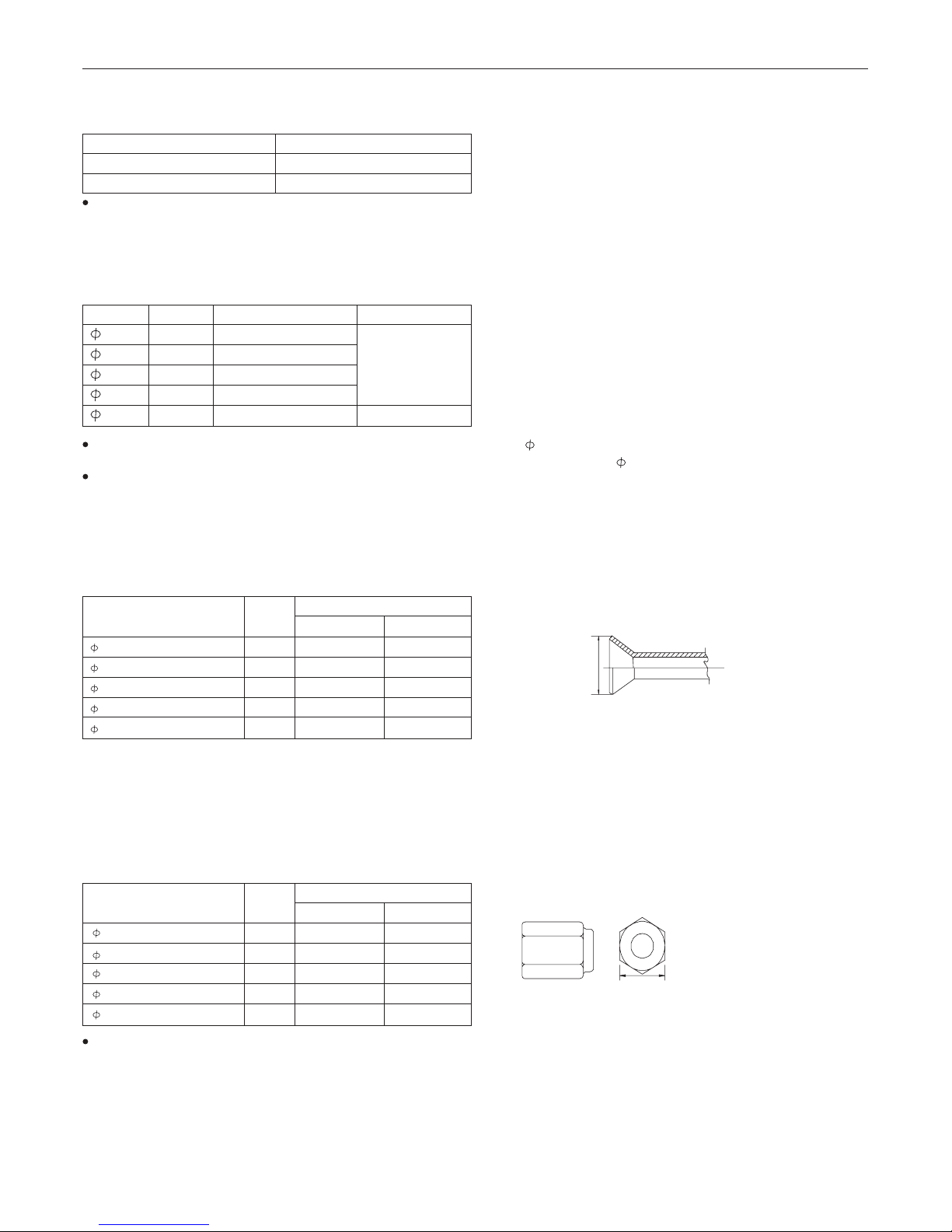
The flare machining dimensions for units that use R410A is larger than those for units that use R22 in order to increase
air tightness.
If a clutch type flare tool is used to machine flares on units that use R410A, make the protruding part of the pipe between
1.0 and 1.5mm. Copper pipe gauge for adjusting the length of pipe protrusion is useful.
Size(mm) Radial Thickness(mm)Size(inch)
Type
Type-O pipes
Type-1/2H or Hpipes
Piping Materials
Types of Copper Pipes (Reference)
The table shows the standards in Japan. Using this table as a reference, choose pipes that meet the local standards.
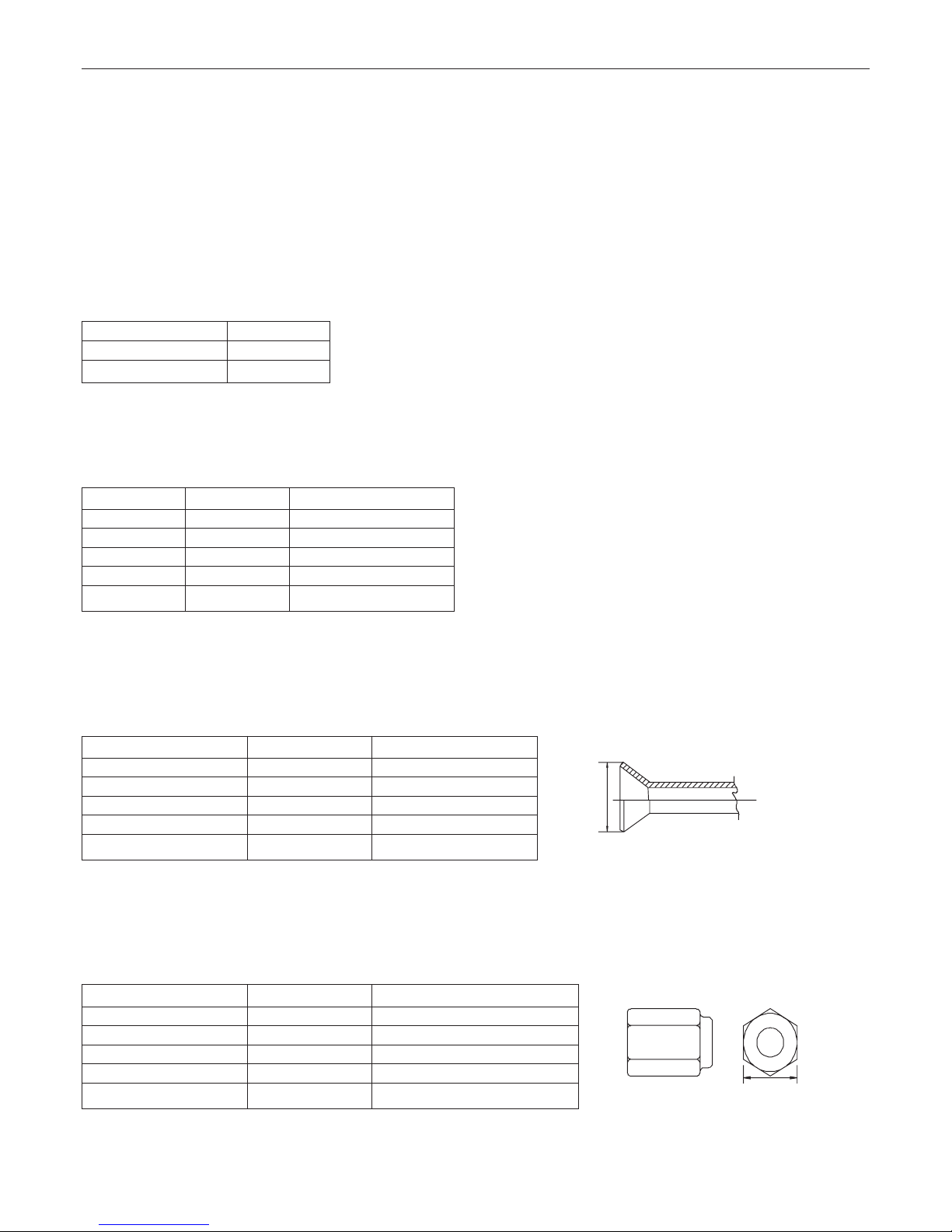
Piping Materials/Radial Thickness
Flare Machining (type-O and OL only)
Flare Machining Dimension(mm)
External dimension of pipes
Size
Dimension A
R410A R22
6.35
9.52
12.7
15.88
19.05
1/4"
3/8"
1/2"
5/8"
3/4"
9.1
13.2
16.6
19.7
24.0
9.0
13.0
16.2
19.4
23.3
Flare Nut
Type-2 flare nuts instead of type-1 nuts are used to increase the strength. The size of some of the flare nuts have also
been changed.
Flare nut dimension(mm)
R410A(Type2) R22(Type1)
6.35
9.52
12.7
15.88
19.05
1/4"
3/8"
1/2"
5/8"
3/4"
17.0
22.0
26.0
29.0
36.0
17.0
22.0
24.0
27.0
36.0
6.35
9.52
12.7
15.88
1/4''
3/8''
1/2''
5/8''
0.8t
0.8t
0.8t
1.0t
19.05 3/4'' 1.0t
Dimension A
External dimension of pipes Size
Dimension B
Dimension B
9
Read Before Installation
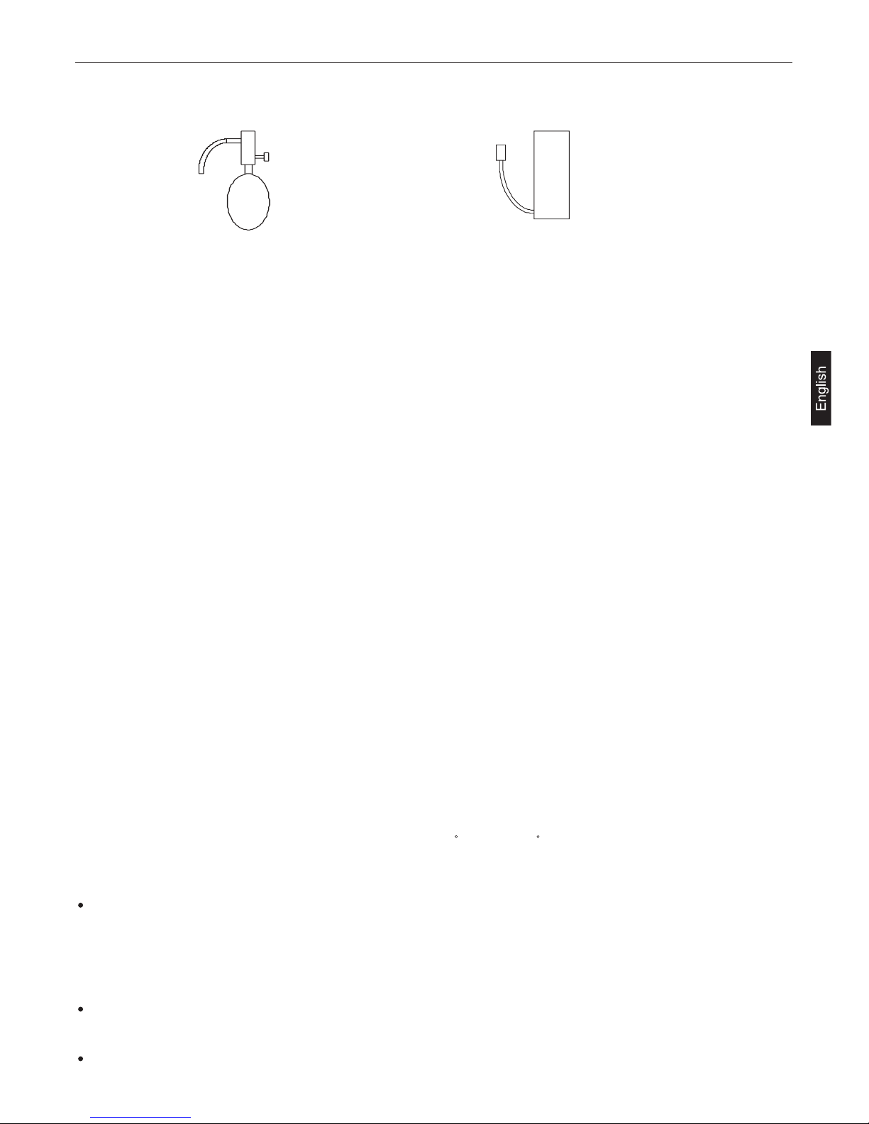
Pressurize the equipment with nitrogen up to the design pressure and then judge the equipment's air tightness, taking
temperature variations into account.
When investigating leakage locations using a refrigerant, be sure to use R410A.
Ensure that R410A is in a liquid state when charging.
Use of oxygen as the pressurized gas may cause an explosion.
Charging with R410A gas will lead the composition of the remaining refrigerant in the cylinder to change and then this
refrigerant can not be used.
Air Tightness Test
No changes from the conventional method. Note that a refrigerant leakage detector for R22 or R407C cannot detect R410A
leakage.
Halide torch
NO
R22 or R407C leakage detector
NO
Items to be strictly observed :
Reasons:
Because R410A is a simulated azeotropic refrigerant, it can be handled in almost the same mammer as a single refrigerant
such as R22. Howerver, if the refrigerant is removed in the vapor phase, the composition of the refrigerant in the cylinder
will somewhat change.
Remove the refrigerant in the liquid phase. Additional refrigerant may be added in case of a refrigerant leak.
Characteristics of the Conventional and the New Refrigerants
Required accuracy of the vacuum gauge
Use a vacuum gauge that can measure up to 650Pa. Do not use a general gauge manifold since it cannot measure a
vacuum of 650Pa.
Vacuuming
Vacuum pump with check valve
A vacuum pump with a check valve is required to prevent the vacuum pump oil from flowing back into the refrigerant
circuit when the vacuum pump power is turned off (power failure). It is also possible to attach a check valve to the actual
vacuum pump afterwards.
Standard degree of vacuum for the vacuum pump
Use a pump which reaches 65Pa or below after 5 minutes of operation.
In addition, be sure to use a vacuum pump that has been properly maintained and oiled using the specified oil. If the
vacuum pump is not properly maintained, the degree of vacuum may be too low.
Evacuating time
Evacuate the equipment for 1 hour after 650Pa has been reached.
After envacuating, leave the equipment for 1 hour and make sure the that vacuum is not lost.
Operating procedure when the vacuum pump is stopped
In order to prevent a backflow of the vacuum pump oil, open the relief valve on the vacuum pump side or loosen the
charge hose to drawn in air before stopping operation.The same operating procedure should be used when using a
vacuum pump with a check valve.
1.
2.
3.
4.
5.
1.
2.
3.
1.
2.
R410A is a pseudo-azeotropic refrigerant (boiling point R32= -52 C, R125= -49 C) and can roughly be handled in the same
way as R22; however, be sure to fill the refrigerant from the liquid side, for doing so from the gas side will somewhat change
the composition of the refrigerant in the cylinder.
Charging Refrigerant
R410A must be in a liquid state when charging.
Reasons:
Note
In the case of a cylinder with a syphon, liquid R410A is charged without turning the cylinder up side down. Check the
type of cylinder before charging.
When refrigerant leaks, additional refrigerant may be charged. (Add the refrigerant from the liquid side)
Remedies to be taken in case of a refrigerant leak
10
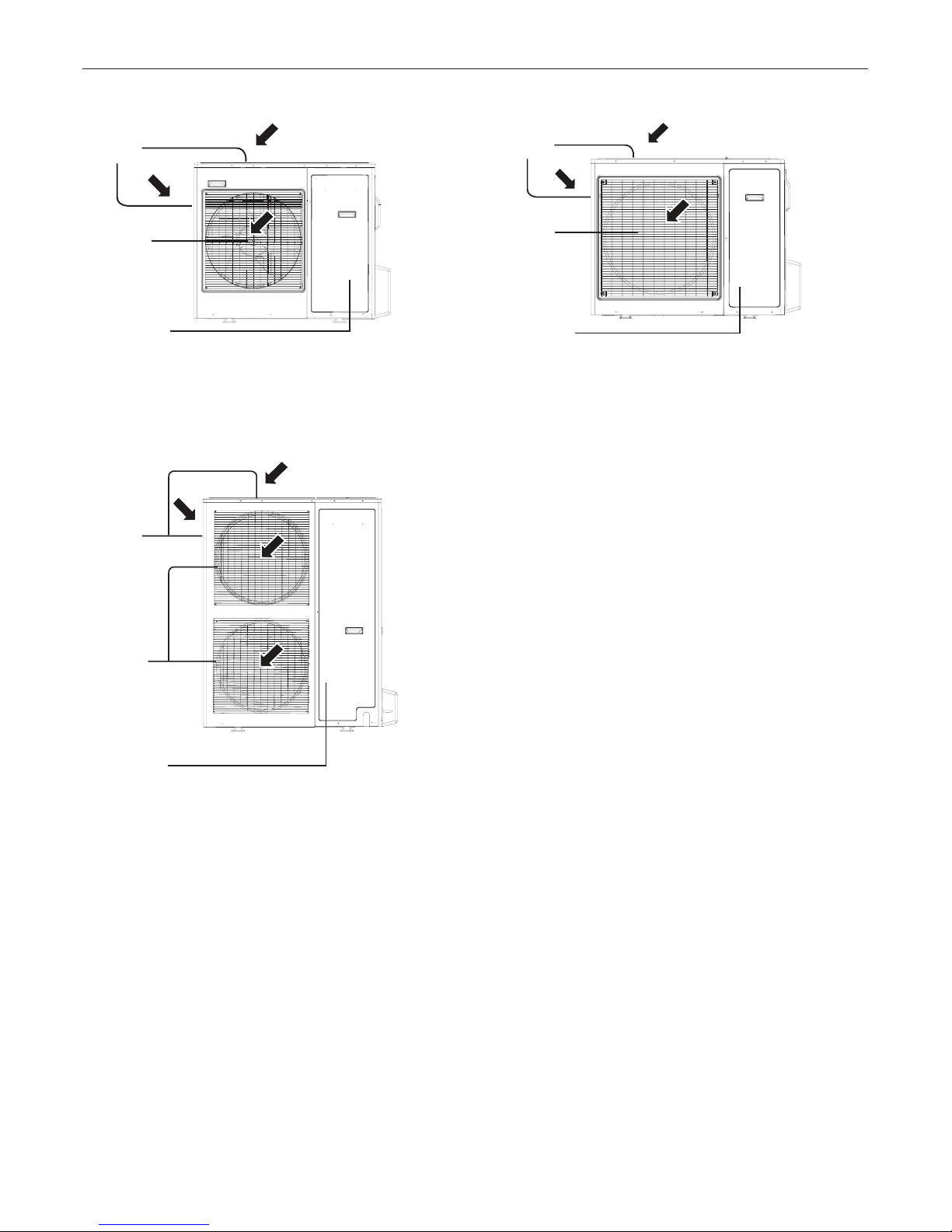
Name of Parts
Air inlet
Compressor
(Inside of unit)
Air inlet
Air outlet
Compressor
(Inside of unit)
Air outlet
1U28HS1ERA 1U36HS1ERA 1U48LS1ERA 1U48LS1ERB
1U48IS1EAB 1U60IS1ERA 1U60IS1ERB 1U60IS1EAB
AU60NAIESA
1U48LS1EAB
Air inlet
Air outlet
(Inside of unit)
Compressor
11
Installation Procedure
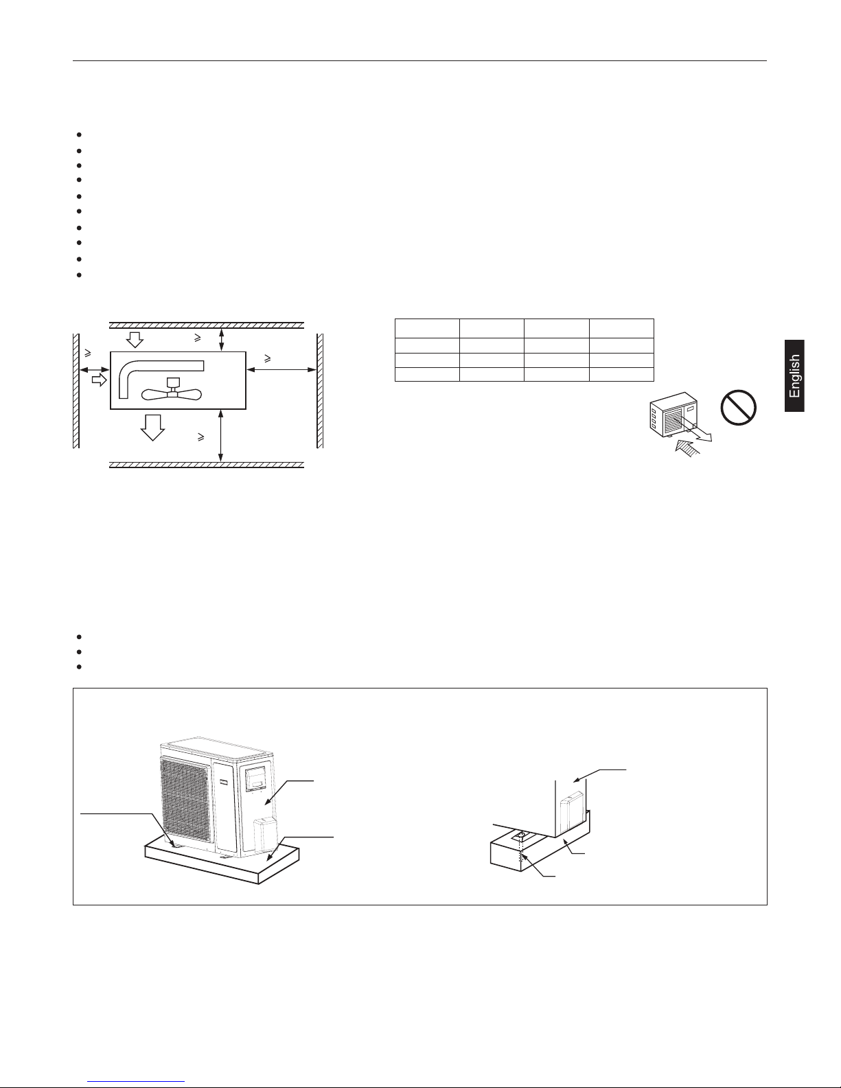
Note :
(1) Fix the parts with screws.
(2) Don't intake the strong wind directly to
the outlet air-flow hole.
(3) A one meter distance should be
kept from the unit top.
(4) Don't block the surroundings of the unit with sundries.
(5) If the outdoor unit is installed in a place that is exposed
to the wind, install the unit so that the outlet grid is NOT
pointing in the direction of the wind.
(a) Concrete foundation (b) Foundation anchor
Concrete foundation
Unit
Anchor bolt
1. Selection of the place of installation
Select the place of installation satisfying the following conditions and, at the same time, obtain a consent from the client or
user.
Place where air circulates.
Place free from heat radiation from other heat sources.
Place where drain water may be discharged.
Place where noise and hot air may not disturb the neighborhood.
Place where there is not heavy snowfall in the winter time.
Place where obstacles do not exist near the air inlet and air outlet .
Place where the air outlet may not be exposed to a strong wind.
Place surrounded at four sides are not suitable for installation. A 1m or more of overhead space is needed for the unit.
Avoid mounting guide-louvers to the place where short-circuit is a possibility.
When installing several units, secure sufficient suction space to avoid short circuiting.
Open space requirement around the unit
Installation of Outdoor Unit
Wind direction
NO
L2
L3
L1
500
(Servicing
space)
Air outlet
Air inlet
Air inlet
Distance
open open
open
500 mm
150 mm150 mm 300 mm
300 mm 300 mm
L1
L2
L3
Case I Case II Case III
Fix the unit on the foundation in a proper way according to the condition of the installation place, referring to the following
information.
2. Installation of outdoor unit
Give enough room for the concrete foundation to fix by anchor bolts.
Place the concrete foundation deep enough.
Install the unit so that the angle of inclination must be less than 3 degrees.
Anchor bolt
Concrete foundation
Unit
To fix by bolts
Installation Procedure
12
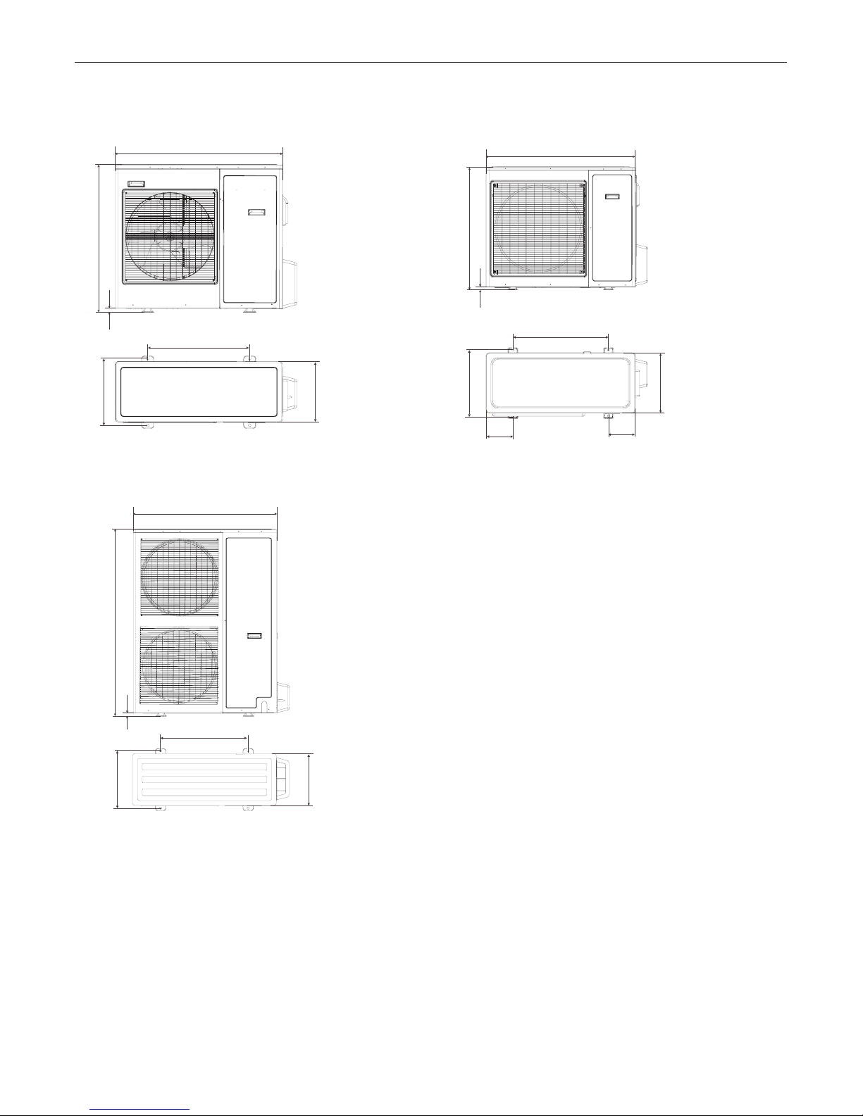
Installation of Outdoor Unit
3. Installation dimension (Unit:mm)
580
1U28HS1ERA 1U36HS1ERA
1U48LS1ERA 1U48LS1ERB 1U48LS1EAB
1U48IS1EAB 1U60IS1ERA 1U60IS1ERB 1U60IS1EAB
AU60NAIESA
380
340
25
580
340
380
948
840
447
410
648
180
180
25
830
1008
25
1250
948
Installation Procedure
13
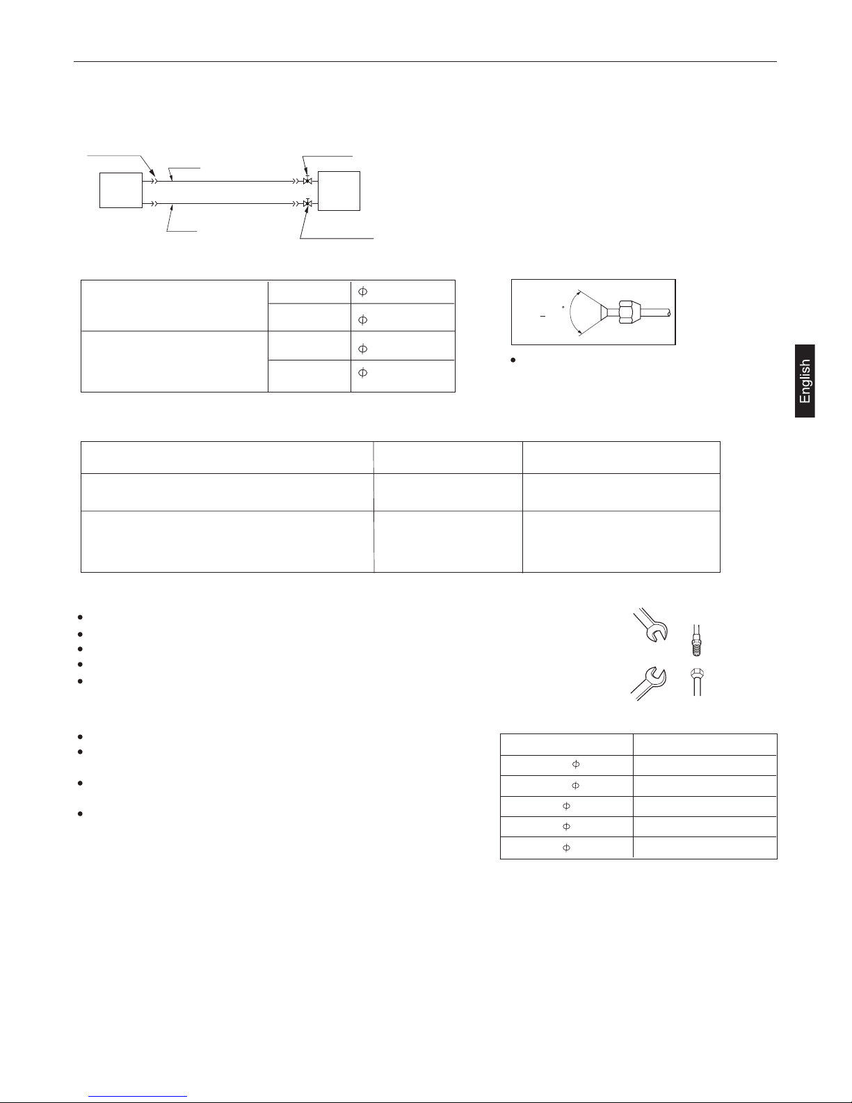
Piping Connection
2. Piping size
3. Limitations for one way piping length and vertical height difference
Precautions for refrigerant piping
Do not twist or crush piping.
Be sure that no dust is mixed in piping.
Bend piping with as wide angle as possible.
Keep insulating both gas and liquid piping.
Check flare-connected area for gas leakage.
Apply refrigerant oil to the joint and the flange.
To bend a pipe, give the roundness as possible not to crush
the pipe.
When connecting pipe, hold the pipe centre to centre and then
screw nut on by hand, refer to Fig.
Be careful not to let foreign matters, such as sands enter
the pipe.
4. Piping connection method
Forced fastening without centering may damage the threads and cause a gas leakage.
Mo de l
One way piping length
Vertical height difference
(between indoor and outdoor)
Install the removed flare nuts to the pipes
to be connected, then flare the pipes.
Gas pipe
15.88x1.0mm
Liquid pipe
Gas pipe
9.52x0.8mm
19.05x1.0mm
Liquid pipe
9.52x0.8mm
90+0.5
1U48LS1ERA 1U48LS1ERB
1U48LS1EAB 1U48IS1EAB
1U60IS1ERA 1U60IS1ERB
1U60IS1EAB AU60NAIESA
1U28HS1ERA 1U36HS1ERA
Pipe diameter Fastening torque (N.m)
Liquid pipe 6.35mm
Gas pipe 15.88mm
Liquid pipe 9.52mm
Gas pipe 19.05mm
14.2-17.2
61.8-75.4
32.7-39.9
97.2-118.6
Gas pipe 12.7mm
49.5-60.3
1. Piping diagram
Outdoor
unit
Gas pipe
Liquid
pipe
Flare connection
Indoor
unit
3-way stop valve
3-way stop valve
less than 30 m less than 20 m
less than 50 m less than 30 m
1U28HS1ERA 1U36HS1ERA
1U48LS1ERA 1U48LS1ERB 1U48LS1EAB
1U48IS1EAB 1U60IS1ERA 1U60IS1ERB
1U60IS1EAB AU60NAIESA
1U28HS1ERA 1U36HS1ERA 1U48LS1ERA 1U48LS1ERB 1U48LS1EAB
1U48IS1EAB 1U60IS1ERA 1U60IS1ERB 1U60IS1EAB AU60NAIESA
Spanner
Spanner
Nut
Joint
Installation Procedure
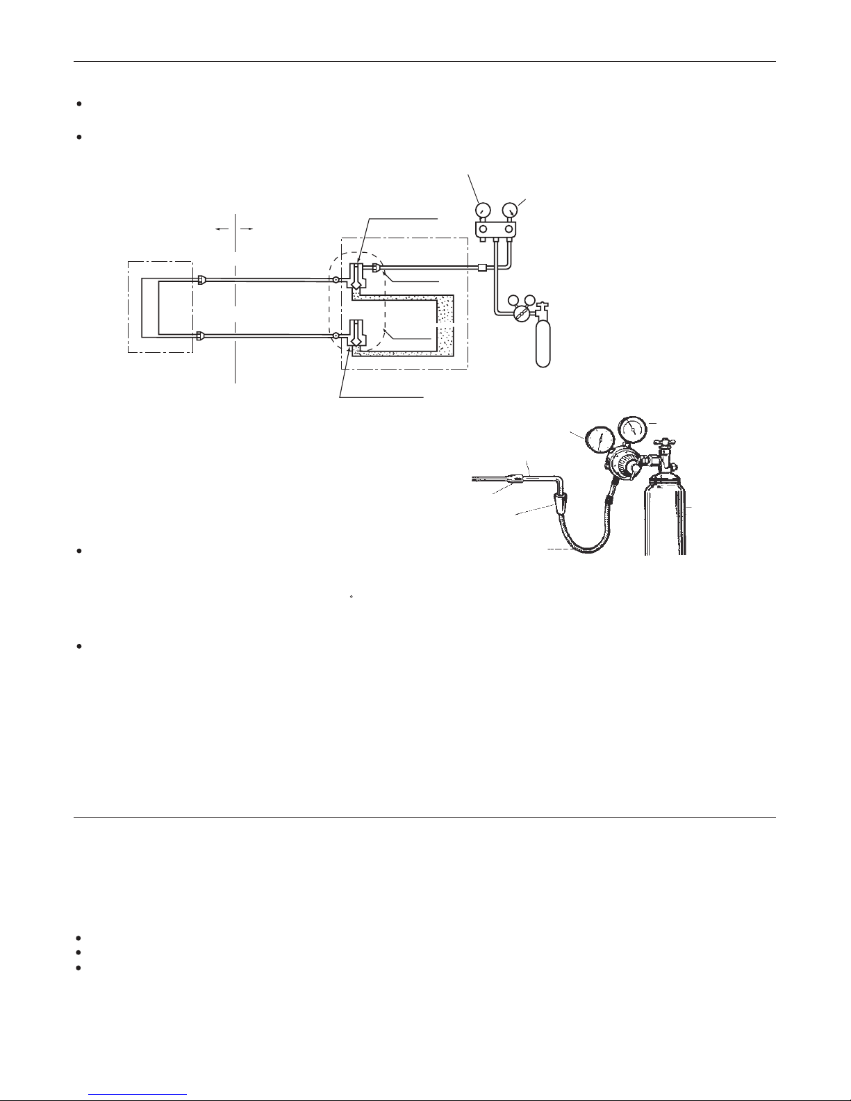
14
The air tightness test adopts nitrogen tank to give pressure according to the pipe connection mode as the following figure
shown.
The gas and liquid valve are all in close state. In order to prevent the nitrogen entering the circulation system of outdoor
unit, tighten the valve rod before giving pressure (both gas and liquid valve rods).
In 1) to 3) steps, if the pressure drops, check the leakage in each joint by listening, touching and using soap water etc.
to identify the leaking point. After confirming the leaking point, welding it again or tighten the nut tightly again.
Checking the leaking point
1) Pressurize for over 3 minutes at 0.3MPa (3.0 kg/cm
2
g).
2) Pressurize for over 3 minutes at 1.5MPa (15 kg/cm2g). A large
leakage will be found.
3) Pressurize for about 24 hours at 3.0MPa (30 kg/cm2g). A small
leakage will be found.
Installation Procedure
When the total length (L) of the two indoor units' connecting pipe is less than 5m, it is unnecessary to charge additional
refrigerant.
If the connecting pipe (L) exceeds 5m, it shall charge M(g) additional refrigerant per meter.
That is: Refrigerant charging amount = (L-5m) x 45 (g/m)
Air Tightness Test
When pressurizing for 24 hours, a variation of 1 C in the ambient temperature will cause a variation of 0.01MPa(0.1kg/cm2g)
in pressure. It shall be corrected during test.
Check if the pressure drops
If the pressure does not drop,
then pass.
If the pressure drops, then please check the leaking point.
Cylinder pressure gauge
Cylinder of nitrogern
Line pressure gauge
Tubing bring brazed
Sweat joint
Large slip-on connector
Service hose
Additional Refrigerant Charge
Outdoor
Completely tightened
Completely tightened
Flare part
Outdoor units
Manhole
Discharging valve
stop valve totally closed
(Gas side)
Low pressure piezometer
High pressure piezometer
Meter separator
Dropping valve
stop valve totally closed
(Liquid side)
Nitrogen tank
VL VH
Indoor units
Indoor
Flare part
After finishing connection of refrigerant pipe, it shall perform air tightness test.
Only in COOLING operation can charge the additional refrigerant.
When charging, the refrigerant shall be charged from the charging nozzle of low pressure valve.
Be carefull when charging refrigerant, do not let the air mix into the system, and must charge the additional refrigerant
in liquid state.
Installation Procedure
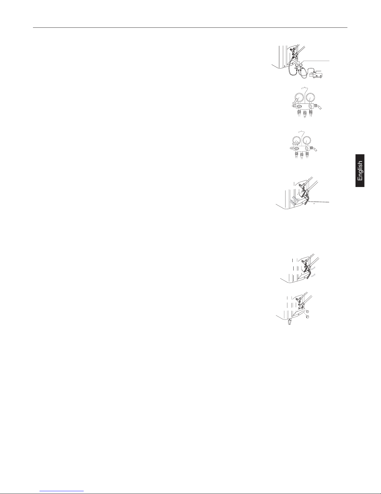
15
Detach the service port's cap of gas stop valve, the valve rod's cap for liquid
stop valve and gas stop valve, and connect the service port into the projection
of charge hose (low) for gaugemanifold. Then connect the projection of
charge hose (center) for gaugemanifold into vacuum pump.
Open the handle at low in gaugemanifold, and operate vacuum pump. If the
scale-moves of gause (low) reach vacuum condition in a moment, check
the step 1 again.
Vacuumize for over 15min. And check the level gauge which should read -
0.1MPa (-76 cm Hg) at low pressure side. After the completion of vacuumizing,
close the handle 'Lo' in the vacuum pump. Check the condition of the scale
and hold it for 1-2min. If the scale-moves back in spite of tightening, make
flaring work again, then return to the beginning of the step 3.
Open the valve rod for the liquid stop valve to an angle of anticlockwise 90
degree. After 6 seconds, close the liquid stop valve and make the inspection
of gas leakge.
No gas leakage? In case of gas leakage, tighten parts of pipe connection. If leakage stops, then proceed the step 6. If it
does not stop gas leakage, discharge whole refrigerants from the service port. After flaring work again and vacuumize,
fill up prescribed refrigerant from the gas cylinder.
Detach the charge hose from the service port, open liquid stop valve and
gas stop valve. Turn the valve rod anticlockwise until hitting lightly.
To prevent the gas leakage, turn the service ports cap, the valve rodis cap
for liquid stop valve and gas stop valve a little more than the point where
the torque increases suddenly.
If the refrigerant of the air conditioner leaks, it is necessary to make all the refrigerant out. Vacuumize first, then charge
the liquid refrigerant into air conditioner according to the amount marked on the nameplate.
Vacuuming
Piping vavuum method: to use vacuum pump
1.
2.
3.
4.
5.
6.
7.
CAUTION:
90
Service port
90 for 6 sec.
Open
Liquid stop valve
Gas stop valve
Gauge manifold(R410A)
Vacuum pump(R410A)
Close
Valve rod cap
Valve rod cap
Service port cap
Liquid stop valve
Gas stop valve
Liquid stop valve
Gas stop valve
Installation Procedure
16
Electrical Wiring
Selection of size of power supply and interconnecting wires
Precautions for Electrical wiring
Electrical wiring work should be conducted only by authorized personnel.
Do not connect more than three wires to the terminal block. Always use round type crimped terminal lugs with insulated
grip on the ends of the wires.
Use copper conductor only.
Select wire sizes and circuit protection from table below. (This table shows 20 m length wires with less than 2% voltage
drop.)
DANGER OF BODILY INJURY OR DEATH
TURN OFF ELECTRIC POWER AT CIRCUIT BREAKER OR POWER SOURCE BEFORE MAKING ANY ELECTRIC
CONNECTIONS.
GROUND CONNECTIONS MUST BE COMPLETED BEFORE MAKING LINE VOLTAGE CONNECTIONS.
WARNING!
Item
Model
Phase
Switch breaker
(A)
Circuit breaker
Overcurrent protector
rated capacity (A)
Power source
wire size
(minimum)
(mm2)
Switch
breaker(A)
Earth leakage breaker
Leak
current(mA)
1U28HS1ERA
1U36HS1ERA
1U48LS1ERA
1U60IS1ERA
301 40 30 6.0 40
3 30 4.0 3020 30
1U48LS1ERB
1U60IS1ERB
AU60NAIESA
1U48LS1EAB
1U48IS1EAB
1U60IS1EAB
3 30 4.0 3020 30
If the supply cord is damaged, it must be replaced by the manufacturer or itsservice agent or a similar qualified person.
If the fuse of control box is broken, please change it with the type of T25A/450VAC;
If the fuse of control PC board is broken, please change it with the type of T3.15A/250VAC. But for 1U28HS1ERA,
1U36HS1ERA,1U48LS1ERA,,1U48LS1ERB,1U60IS1ERA,1U60IS1ERB, AU60NAIESA, the type is T6.3A/250VAC.
The wiring method should be in line with the local wiring standard.
The power cable and connecting cable should be self-provided.
All the cables shall have got the European authentication certificate. During installation, when the connecting cables
break off, it must be assured that the grouding wire is the last one to be broken off.
The breaker of the air conditioner should be all-pole switch; and the distance between its two contacts should not be no
less than 3mm. Such means for disconnection must be incorporation in the fixed wiring.
The distance between its two terminal blocks of indoor unit and outdoor unit should not be over 5m. If exceeded, the
diameter of the wire should be enlarged according to the local wiring standard.
A leakage breaker must be installed.
The specification of power cable
For models 1U28HS1ERA, 1U36HS1ERA,
1U48LS1ERA,1U60IS1ERA
the power cable should be H05RN-F 3G 6.0mm2.
For models 1U48LS1EAB,
1U48IS1EAB,
1U60IS1EAB, 1U48LS1ERB, 1U60IS1ERB, AU60NAIESA, the power cable
should be H07RN-F 5G 4.0mm
2
.

Installation Procedure
17
Installation Procedure
Electrical Wiring
Wiring procedure
1) Remove set screws on the side before taking off the front panel toward the direction.
2) Connect wires to the terminal block correctly and fix the wires with a wire clamp equipped nearby the terminal block.
3) Route the wires in a proper way and penetrate the wires through the opening for electrical wiring on the side panel.
WARNING:
INTERCONNECTING WIRES MUST BE WIRED ACCORDING TO FIGURE BELOW. INCORRECT WIRING MAY CAUSE
EQUIPMENT DAMAGE.
Test Run
CAUTION!
THIS UNIT WILL BE STARTED INSTANTLY WITHOUT "ON" OPERATION WHEN ELECTRIC POWER IS SUPPLIED.
BE SURE TO EXECUTE "OFF" OPERATION BEFORE ELECTRIC POWER IS DISCONNECTED FOR SERVICING.
This unit has a function of automatic restart system after recovering power stoppage.
1. Before starting test run (for all Heat pump models)
Confirm whether the power source breaker (main switch) of the unit has been turned on for over 12 hrs to energize the
crankcase heater in advance of operation.
2.Test run
Suction pressure at check joint of service valve for gas pipe.
Discharge pressure at check joint on the compressor discharge pipe.
Temperature difference between return air and supply air for indoor unit.
Run the unit continuously for about 30 minutes, and check the following.
Power supply :1PH,220-230V~,50Hz
Outdoor unit
terminal block
To indoor unit
Y/G
1 2 3L N
1U28HS1ERA 1U36HS1ERA 1U48LS1ERA 1U60IS1ERA
1U48LS1ERB 1U48LS1EAB 1U48IS1EAB 1U60IS1ERB 1U60IS1EAB AU60NAIESA
Outdoor unit
terminal block
Indoor unit
terminal block
Power supply:380-400V, 3N~,50Hz
Y/G
1 2 3
Y/G
1 2 3
R S T N
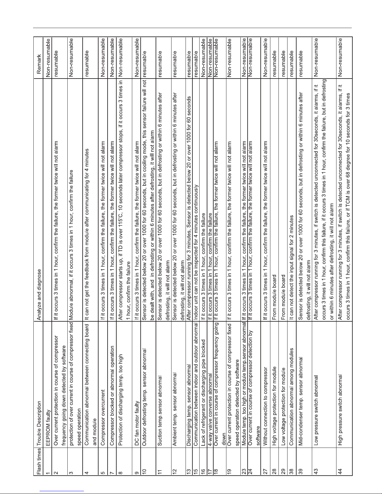
Troubleshooting
18
1U28HS1ERA/1U36HS1ERA/1U48LS1ERA/1U48LS1ERB/1U60IS1ERA/1U60IS1ERB/AU60NAIESA
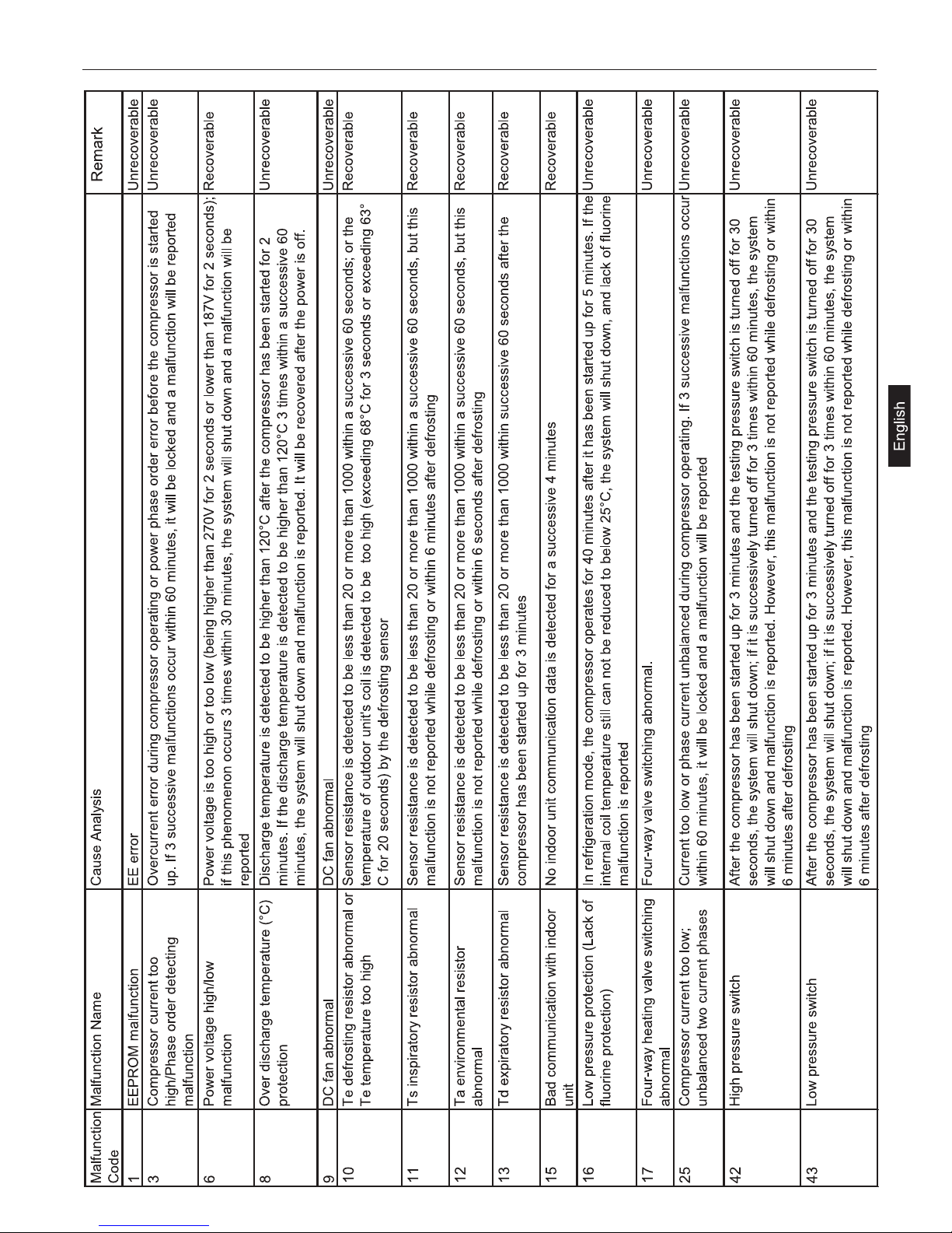
Troubleshooting
19
1U48LS1EAB/1U48IS1EAB/1U60LS1EAB
MANUAL DE INSTALACIÓN DEL APARATO DE AIRE
ACONDICIONADO DE TIPO SINGLE SPLIT
l
Lea detenidamente este manual antes de instalar el aparato.
Guarde este manual de uso para futuras consultas.
Precauciones de seguridad 3
Denominación de los componentes 7
Tuberías refrigerante 8
Instalación de la unidad exterior 10
Medidas 11
Tuberías refrigerante 12
Test de estanquidad 13
Carga adicional de refrigerante 13
Realización
del vacío 14
Conexiones eléctricas 15
Prueba de funcionamiento 16
Diagnóstico 17
Contenido
Español
1U28HS1ERA
1U36HS1ERA
1U48IS1EAB
1U60IS1ERA
1U60IS1ERB
1U60IS1EAB
AU60NAIESA
1U48LS1ERA
1U48LS1ERB
1U48LS1EAB
CONFORMIDAD DE LOS MODELOS
SEGÚN LAS NORMATIVAS EUROPEAS
CE
Todos los productos cumplen los requisitos de las siguientes
normas europeas:
- Directiva de baja tensión 73/23/CEE
- Directiva de baja tensión 2006/95/CE
- Compatibilidad electromagnética 89/336/CEE
- Compatibilidad electromagnética 2004/108/CE
ROHS
Los productos cumplen los requisitos de la directiva 2002/95/
CEE establecida por el Parlamento Europeo y el Consejo sobre
la Restricción del uso de determinadas sustancias peligrosas en
aparatos eléctricos y electrónicos (Directiva RoHS de la Unión
Europea).
WEEE
De acuerdo con la directiva 2002/96/CE del Parlamento Europeo,
se informa al consumidor acerca de los requisitos que han de
cumplirse para deshacerse de productos eléctricos y electrónicos.
REQUISITOS DE DESECHO:
Su aparato de aire acondicionado ha sido
marcado con este símbolo que significa que
los productos de tipo eléctrico y electrónico
no deben mezclarse con la basura doméstica
sin clasificar. No intente desmontar el sistema
por sí mismo: tanto el desmontaje del sistema de aire
acondicionado como la manipulación del refrigerante, el
aceite y cualquier otro componente deben ser llevados
a cabo por un instalador cualificado, de acuerdo con la
legislación local y nacional aplicable. Los aparatos de aire
acondicionado deben ser tratados en instalaciones de
manipulación especializadas para su reutilización, reciclado
y recuperación. Al garantizar la correcta eliminación de
este producto, estará contribuyendo a evitar las posibles
consecuencias negativas que podría provocar sobre el
medioambiente y la salud humana. Póngase en contacto
con el instalador o la autoridad local pertinente si desea
obtener más información. Las pilas deben ser extraídas del
mando a distancia y eliminadas de forma independiente, de
acuerdo con la legislación local y nacional aplicable.
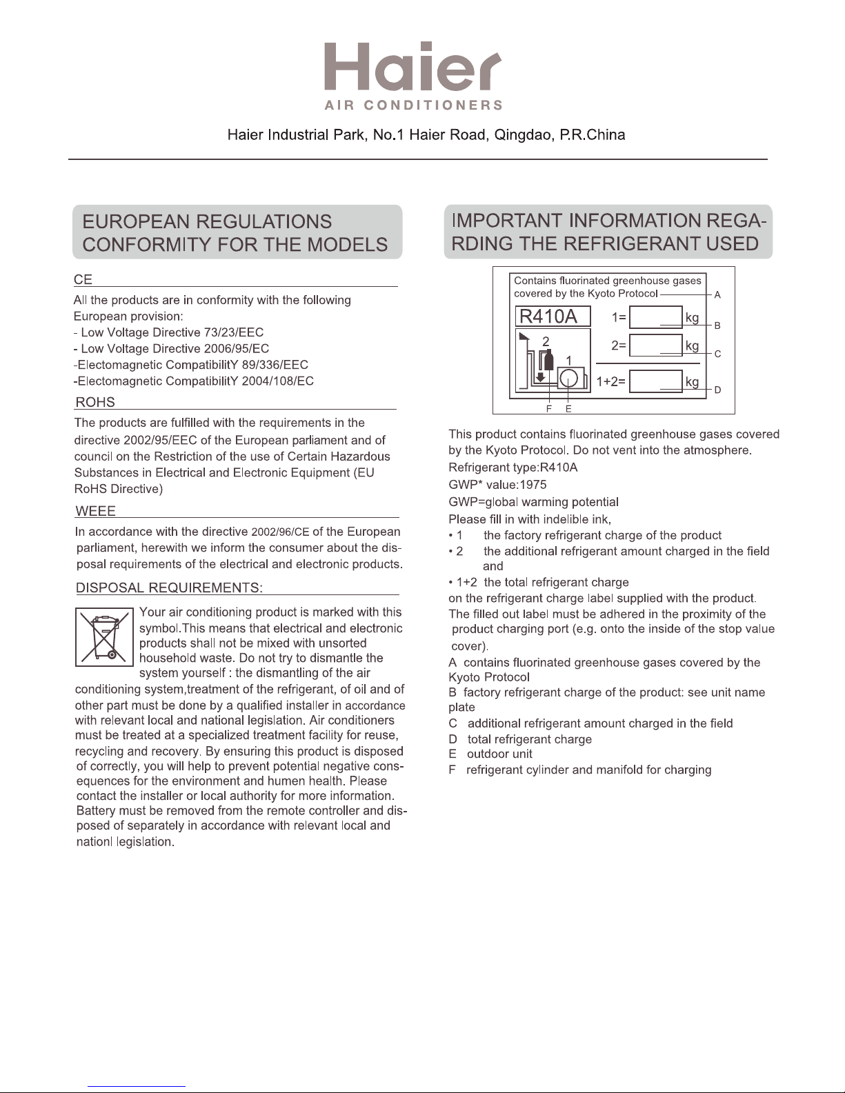
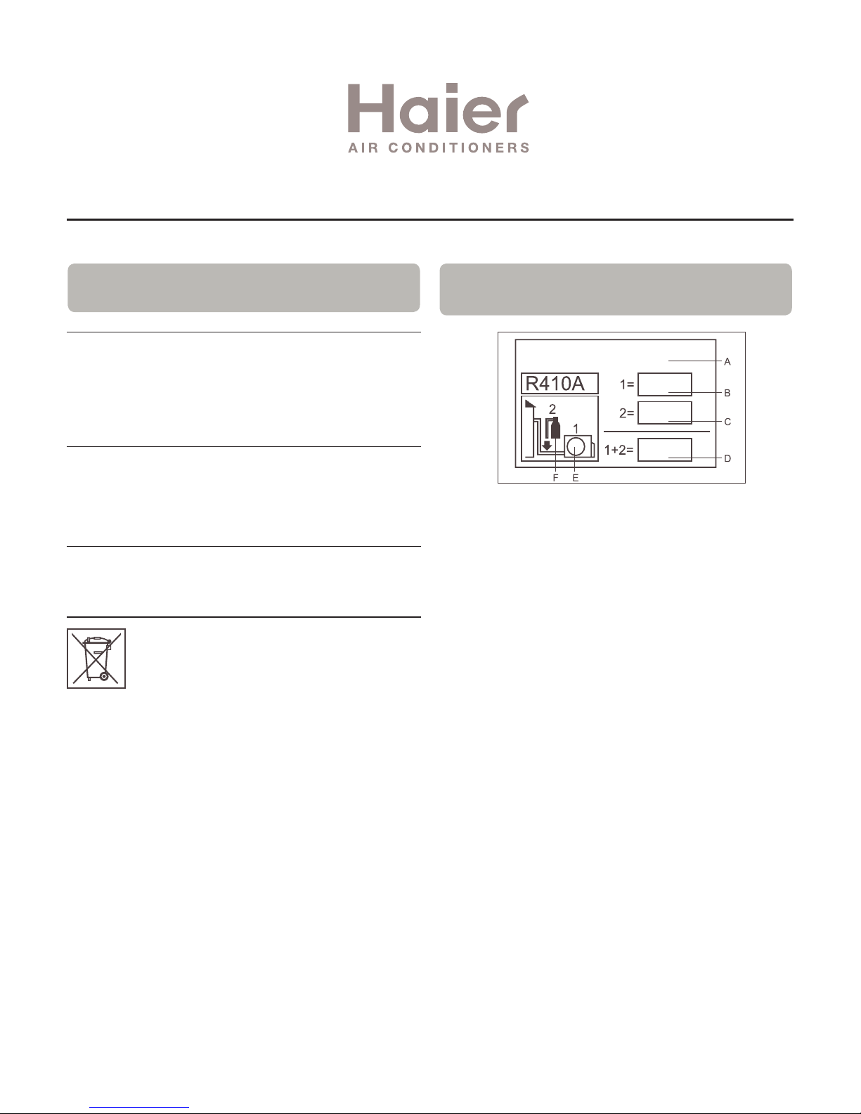
INFORMACIÓN IMPORTANTE ACERCA DEL REFRIGERANTE UTILIZADO
Este producto contiene gases fluorados de efecto invernadero
regulados por el Protocolo de Kioto. No los libere a la atmósfera.
Tipo de refrigerante: R410A
Valor GWP*: 1975 1975
GWP = Potencial de contribución al calentamiento global
Escriba con tinta indeleble:
• 1 La carga de refrigerante que contiene el producto de fábrica
• 2 La cantidad de refrigerante adicional cargada in situ y
• 1+2 La carga total de refrigerante en la etiqueta de refrigerante
suministrada con el producto. Una vez escritos los datos
correspondientes, la etiqueta deberá adherirse cerca de la
conexión de carga del producto (por ejemplo, sobre la parte interna
de la cubierta de la válvula de retención).
A Contiene gases fluorados de efecto invernadero regulados por
el Protocolo de Kioto.
B Carga de refrigerante que contiene el producto de fábrica:
consulte la placa de características de la unidad.
C Cantidad de refrigerante adicional cargada in situ.
D Carga total de refrigerante.
E Unidad exterior.
F Botella de refrigerante y analizador para carga.
Haier Industrial Park, No.1 Haier Road, Qingdao, República Popular China
Contiene gases fluorados de efecto invernadero
regulados por el Protocolo de Kioto.
Kg
Kg
Kg
3
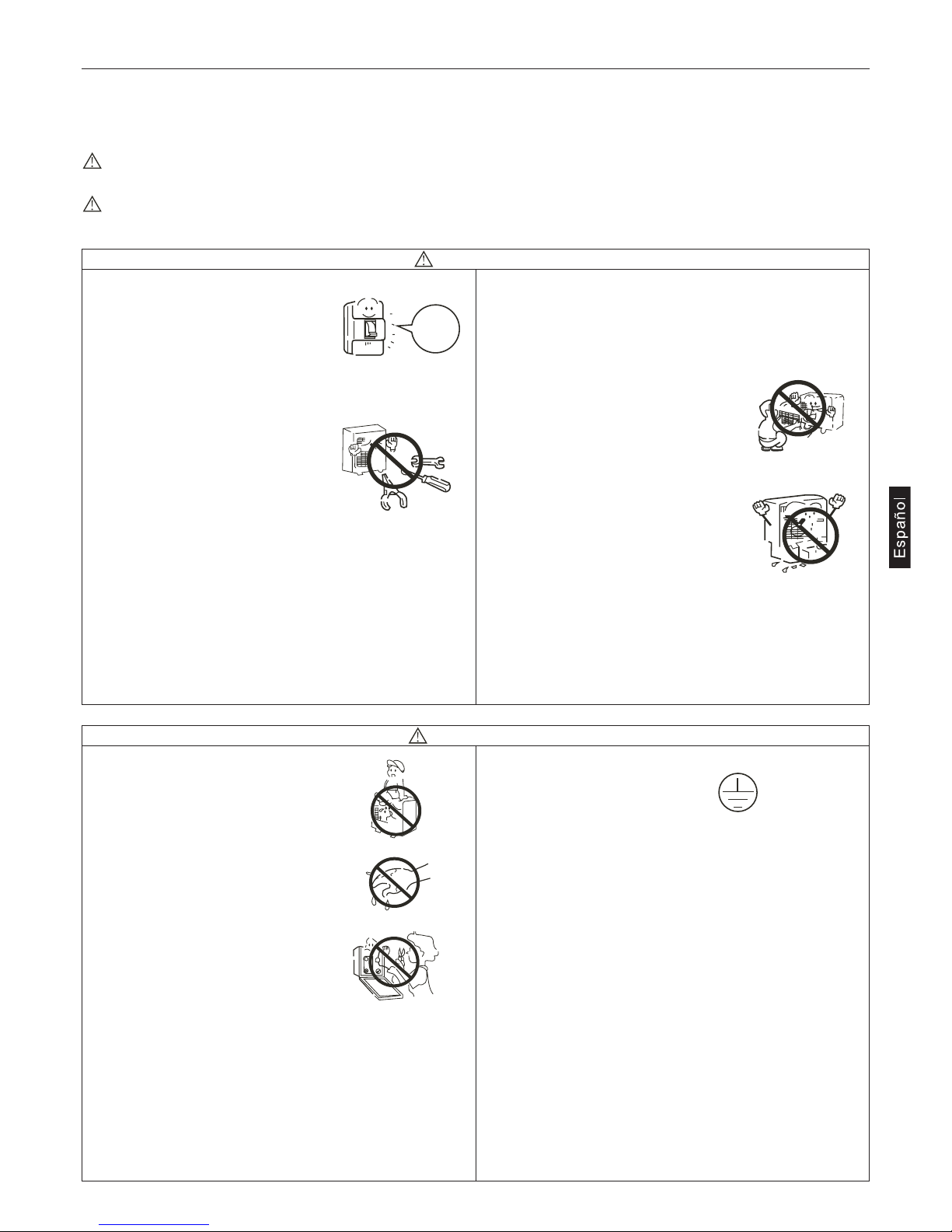
• No apoye ningún objeto sobre el
aparato ni se suba encima del mismo.
• No toque el aparato con las manos
mojadas.
• Use un fusible con las especificaciones
adecuadas.
• No coloque o use gases inflamables
cerca del aparato, ya que podrían producirse incendios.
• Antes de limpiar el aparato, apague el climatizador y
desconecte la alimentación.
• No vierta agua sobre el climatizador para limpiarlo.
• Conecte el cable de toma de
tierra.
• Instale el tubo de desagüe del agua de condensación en
modo correcto, ya que en caso contrario podrían
producirse pérdidas de agua.
• No instala el climatizador en lugares en los que pudieran
producirse pérdidas de gas inflamable.
• Puede ser útil instalar un magnetotérmico de protección
para evitar descargas eléctricas.
• Le recordamos que la instalación de los aparatos debe
realizarse de acuerdo con las normas para permitir el
acceso directo a los mismos para su mantenimiento.
Queda excluido de la cobertura de la garantía el uso
eventual de andamiajes, grúas, etc. para realizar el
mantenimiento.
Antes de usar el climatizador lea las siguientes precauciones de seguridad.
Las precauciones de seguridad que figuran a continuación se subdividen en PELIGRO y ATENCIÓN
La palabra “PELIGRO” corresponde a precauciones que, en caso de no observarse, pueden comportar serias consecuencias
como muerte, lesiones graves, etc.
La palabra “ATENCIÓN” también corresponde a precauciones que, en caso de no observarse, pueden causar serios
problemas, según la situación.
• En caso de anomalías como olor de
quemado, desconecte inmediatamente
el suministro eléctrico y contacte con el
servicio de asistencia. Si el aparato
siguiera funcionando, se podría dañar y
se podrían producir descargas eléctricas o incendios.
• Póngase en contacto con el Servicio de
Asistencia para eventuales reparaciones. Las reparaciones incorrectas pueden ocasionar pérdidas de agua, electrocuciones o incendios.
• Mentre l'apparecchio è in funzione, non inserire dita o altri
oggetti nelle griglie di aspirazione e di uscita. La ventola all'interno gira ad alta velocità ed è molto pericolosa.
• Mientras el aparato esté funcionando no introduzca los
dedos u otros objetos en las rejillas de aspiración o de salida.
La turbina gira dentro a alta velocidad y es muy peligrosa.
• Póngase en contacto con el servicio de asistencia en caso de
pérdida de refrigerante. Si la concentración de refrigerante en
el aire supera una determinada cantidad, puede ser peligroso respirarlo, sobretodo si las dimensiones de la estancia son
reducidas.
• No retire la rejilla de salida de la unidad exterior: Un eventual contacto
con la turbina puede ser muy peligroso.
• Después de que el climatizador haya
estado instalado durante mucho
tiempo verifique la solidez de la base
de soporte de la unidad exterior.
Si la base de soporte está dañada, el aparato puede caer y
ocasionar daños a personas y cosas.
PELIGRO
Precauciones de seguridad
OFF
ATENCIÓN

Se ruega que lean las presentes “Precauciones de Seguridad” antes de proceder a la atenta ejecución del trabajo de instalación.
Después de la instalación, explique al cliente el funcionamiento y las normas para el mantenimiento del aparato.
Las precauciones que se reúnen en la columna “ATENCIÓN” indican que un comportamiento impropio podría tener serias consecuencias como la muerte, lesiones graves, etc. De todos modos, también las precauciones agrupadas en la columna “ADVERTENCIAS” se refieren a situaciones que podrían comportar consecuencias muy graves.
ATENCIÓN
• Póngase en contacto con el Servicio de Asistencia para eventuales reparaciones. Las reparaciones de carácter eléctrico deberán ser
realizadas por electricistas cualificados. Las operaciones inadecuadas pueden ocasionar graves daños al usuario.
• Se ruega que confíen la instalación a la empresa que ha vendido el aparato o a un instalador profesional. Defectos debidos a una
instalación inadecuada podrían provocar pérdidas de agua, descargas eléctricas e incendios, una vez caducada la garantía.
• Realice la instalación con cuidado, siguiendo las indicaciones del manual de instalación.
Una instalación inadecuada podría ocasionar pérdidas de agua, descargas eléctricas e incendios, una vez caducada la garantía.
• Para la instalación, verifique que el lugar de instalación pueda sostener con facilidad el peso de la unidad.
Si el soporte es insuficiente, una caída del aparato podría ocasionar heridas graves.
• Respete las instrucciones de instalación prescritas para la eventualidad de que se den condiciones atmosféricas adversas. Una instalación inadecuada puede provocar incidentes debidos a la violenta caída del aparato
• Para las conexiones eléctricas, se ruega que sea un electricista autorizado quien realice la instalación, siguiendo las normas de seguridad relativas a los equipos eléctricos, las normas locales y las instrucciones de instalación, y que se usen circuitos adecuados. Una
capacidad insuficiente del circuito y una instalación defectuosa pueden ser la causa de descargas eléctricas y de incendios.
• Todos los circuitos deben estar provistos de toma de tierra. Asegúrese que la fuerza exterior del cable no descargue sobre la caja
de conexiones, fijándolo adecuadamente. Una conexión o una fijación inadecuadas podrían ocasionar un recalentamiento o un
incendio.
• Conecte correctamente el cable de conexión entre la unidad interior y la exterior. Fije fuertemente la tapa de la caja de bornes ara
evitar recalentamiento, descargas eléctricas o incendios.
ADVERTENCIAS
• Realice una toma de tierra adecuada. No conecte el cable de toma de tierra a tubos del gas, tubos del agua o cables del teléfono.
Una toma de tierra insuficiente puede provocar descargas eléctricas.
• En clase A es necesario instalar un disyuntor de corriente para evitar descargas eléctricas accidentales.
• Realice el desagüe del agua de condensación de acuerdo con lo que se indica en el presente manual, de lo contrario pueden producirse pérdidas de agua.
• Realice el aislamiento térmico de las tuberías del gas y del líquido. Si el aislamiento térmico no fuera el adecuado, se podría formar
agua de condensación con la consiguiente pérdida de agua.
• Ubicar el aparato lejos de televisores, radios o aparatos que generen ondas electromagnéticas u ondas de alta frecuencia.
• No instale la unidad en las siguientes ubicaciones:
a) Posición expuesta a salpicaduras de aceite o emisiones de vapor (cocina), para evitar pérdidas de agua o envejecimiento de las par-
tes de plástico.
b) Lugares donde se produzcan gases corrosivos, para no dañar las tuberías de cobre.
c) Lugar sujeto a fuertes radiaciones, que pueden perturbar el control de la unidad.
d) Lugar en el que haya gases inflamables o sustancias volátiles (gasolina), para evitar riesgos de incendio.
Precauciones de seguridad
4
ATENCIÓN
• No toque el intercambiador de calor con las manos sin pro-
tección, está afilado y es peligroso.
• En caso de pérdida de gas refrigerante ventile adecuadamen-
te la estancia. Si se expone a fuentes de calor, el refrigerante
derramado puede provocar gases tóxicos.
• No intente modificar los dispositivos de seguridad de la insta-
lación. No use recambios distintos a los originales, puede ocasionar incendios o explosiones.
• En caso de instalación en locales reducidos, prevenir los ries-
gos de asfixia debidos a la pérdida de refrigerante.
Consulte con el personal cualificado y autorizado.
• En caso de traslado, consulte con el personal cualificado y
autorizado. Una instalación inadecuada puede ocasionar pérdidas de gas, agua, electrocuciones, humo, incendios.
• Una vez completada la instalación, compruebe que no haya
pérdidas de refrigerante. Si se expone a fuentes de calor, el
refrigerante derramado puede provocar gases tóxicos.
• Use sólo recambios originales. La instalación debe ser realiza-
da por personal cualificado y autorizado. Una instalación
inadecuada puede ocasionar pérdidas de gas, agua, electro-
cuciones, humo, incendios.
PRECAUCIONES PARA EL USO DE UNIDADES CON
GAS R410A
No use las tuberías refrigerantes existentes.
• El refrigerante antiguo y el aceite refrigerante en las tuberías
existentes contienen una gran cantidad de cloro que puede
deteriorar el aceite refrigerante de la nueva unidad.
• El gas R410A es un refrigerante de alta presión y el uso de
tuberías existentes puede provocar explosiones.
Mantenga las superficies exteriores e interiores de los tubos lim-
pias y libres de azufre, óxidos, polvo, residuos del embridado,
grasa y humedad.
• Eventuales contaminaciones dentro de las tuberías del gas
provocan el deterioro del refrigerante.
Para el vacío use una bomba con electroválvula que impida el
retorno del aceite a la instalación en caso de interrupción accidental del suministro eléctrico.
• En caso de uso de bombas con otros tipos de válvulas, el
aceite de la bomba volverá a estar en circulación con el refrigerante ocasionando el deterioro del mismo.
Use instrumentos exclusivamente para refrigerante R410A.
No use los siguientes instrumentos que han sido usados por
otros tipos de refrigerante: látigos, llave dinamométrica, detector pérdidas de gas, bomba para el vacío cuando está desprovista de electroválvula, cilindro recarga, grupo manométrico,
instrumentos para intervenciones en el refrigerante.
• Si el refrigerante y/o aceite residual que se halla en estos instrumentos entra en contacto con el gas R410A provocan su
deterioro.
• Los detectores de pérdida de gas convencionales no funcionan en presencia de gas R410A ya que no contiene cloro.
Deje aparte las tuberías que deberá usar para la instalación de las
unidades interiores y mantenga ambos extremos bien sellados
hasta el momento del uso. (mantenga también embaladas las
juntas)
• Si el polvo, suciedad o agua entran en contacto con el ciclo
del refrigerante, pueden ocasionar el deterioro del aceite y
malos funcionamientos del compresor.
Use una pequeña cantidad de éter o benceno que untará sobre
los empalmes y la brida.
• Grandes cantidades de aceite mineral pueden provocar el
deterioro del aceite de la unidad.
Use refrigerante líquido para cargar el sistema.
• No use gas refrigerante para cargar la unidad porque la composición del gas sufre una modificación en los cilindros que
causa disminuciones de prestaciones.
No use cilindros para la carga.
• El uso de cilindros para la carga modifica la composición del
refrigerante.
Preste especial atención mientras se usan los instrumentos
para la instalación.
• La introducción de cuerpos extraños, como polvo, suciedad
o agua, en el ciclo del refrigerante provocan el deterioro del
aceite de la unidad.
Use sólo refrigerante R410A.
El uso de los refrigerantes que contienen cloro (p. ej.: R22) provocan el deterioro del refrigerante.
Precauciones de seguridad
5

No instale la unidad en lugares con posibles escapes de gas
inflamable.
• La acumulación de gas en los alrededores de la unidad puede provocar un incendio.
No use el aparato para conservar comida, obras de arte, apa-
ratos de precisión, para la cría de animales o el cultivo de plantas.
• El climatizador no es adecuado para usos distintos a la climatización del local.
No use el aparato en condiciones de contaminación excepcional.
• El uso del aparato en presencia de grandes cantidades de
aceite, vapor, ácido, disolventes o tipos especiales de spray
puede comportar una notable pérdida de prestaciones y/o
malos funcionamientos y riesgo de incendio o electrocuciones.
• La presencia de disolventes orgánicos y gases corrosivos
(como amoníaco, compuestos de azufre y ácidos) pueden
provocar pérdidas de gas o de agua.
En caso de instalación del aparato en hospitales, adopte las
medidas necesarias contra el ruido.
• Los instrumentos médicos de alta frecuencia pueden interferir con el normal funcionamiento del climatizador y viceversa.
No instale la unidad sobre objetos que teman la humedad.
• Cuando el nivel de humedad superar el 80%, o cuando el sistema de drenaje es obstruido las unidades interiores pueden
gotear. En caso de instalación de un sistema de drenaje centralizado por las unidades exteriores considere la necesidad
de prevenir el goteo de las unidades interiores.
PRECAUCIONES PARA LA INSTALACIÓN, LA REUBICACIÓN DE LA UNIDAD O INTERVENCIONES EN LAS INSTALACIONES ELÉCTRICAS
Realice una toma de tierra adecuada.
• No conecte el cable de toma de tierra a tubos del gas, tubos
del agua o cables del teléfono. Una toma de tierra insuficiente
puede provocar descargas eléctricas o incendios y el ruido
causado por una toma de tierra inadecuada puede provocar
malos funcionamientos.
Asegúrese de que los cables no estén sujetos a tensiones.
• Si los cables están demasiado tensos se pueden romper o
generar recalentamientos, humo e incendios.
Instale un detector de dispersión eléctrica (interruptor diferencial
Clase A) para evitar electrocuciones, humo e incendios.
Use interruptores y materiales eléctricos conformes con las
especificaciones técnicas declaradas en el manual.
• El uso de fusibles sobredimensionados, cables de acero o de
cobre pueden dañar la unidad y ocasionar humo e incendios.
No salpique agua sobre el aparato ni lo sumerja en agua.
• El contacto del aparato con el agua puede provocar electrocuciones.
Controle periódicamente los soportes sobre los que está montado el aparato para prevenir la caída del mismo.
• Si el aparato está montado sobre soportes defectuosos puede caer y provocar daños.
Para la instalación de los desagües del agua de condensación,
siga atentamente las instrucciones y asegúrese de que drenan
correctamente el agua para evitar la formación de agua de condensación.
• Una instalación inadecuada puede ocasionar pérdidas de
agua y daños en el mobiliario
Elimine los materiales del embalaje de modo adecuado.
• Los embalajes pueden contener clavos, elimínelos de modo
adecuado para evitar daños y heridas. Las bolsas de plástico
suponen un riesgo de asfixia para los niños, rómpalas antes
de eliminarlas para evitar accidentes.
PRECAUCIONES PARA LA PRUEBA DE FUNCIONAMIENTO
No toque los interruptores con las manos mojadas.
No toque las tuberías refrigerantes con las manos desprotegidas durante e inmediatamente después del funcionamiento.
• En base al estado del refrigerante en el sistema, algunas partes como las tuberías y el compresor pueden estar muy frías
o calientes y causar heridas y quemaduras.
No ponga en aparato en funcionamiento sin el panel y la rejilla
de seguridad.
• Estos dispositivos de seguridad sirven para prevenir heridas
debidas al contacto accidental con el ventilador, elevadas
temperaturas o voltaje.
No interrumpa el suministro eléctrico inmediatamente después
del apagado de la unidad.
• Espere como mínimo 5 minutos después del apagado para
evitar pérdidas de agua u otros problemas.
Nunca ponga en funcionamiento el aparato sin filtro del aire.
• Partículas de polvo presentes en el aire pueden obstruir el sistema y causar malos funcionamientos.
COMPRUEBE
1. El tipo de refrigerante usado por la unidad que desea insta-
lar. Tipo de refrigerante: R410A.
2. Las indicaciones para la instalación que figuran en el siguien-
te manual.
3. Las precauciones de seguridad contenidas en el siguiente
manual.
4. En caso de pérdida de gas o de refrigerante expuesto a lla-
mas libres, pueden formarse gases y ácidos nocivos.
Mantenga el local bien ventilado.
Precauciones para la instalación
6
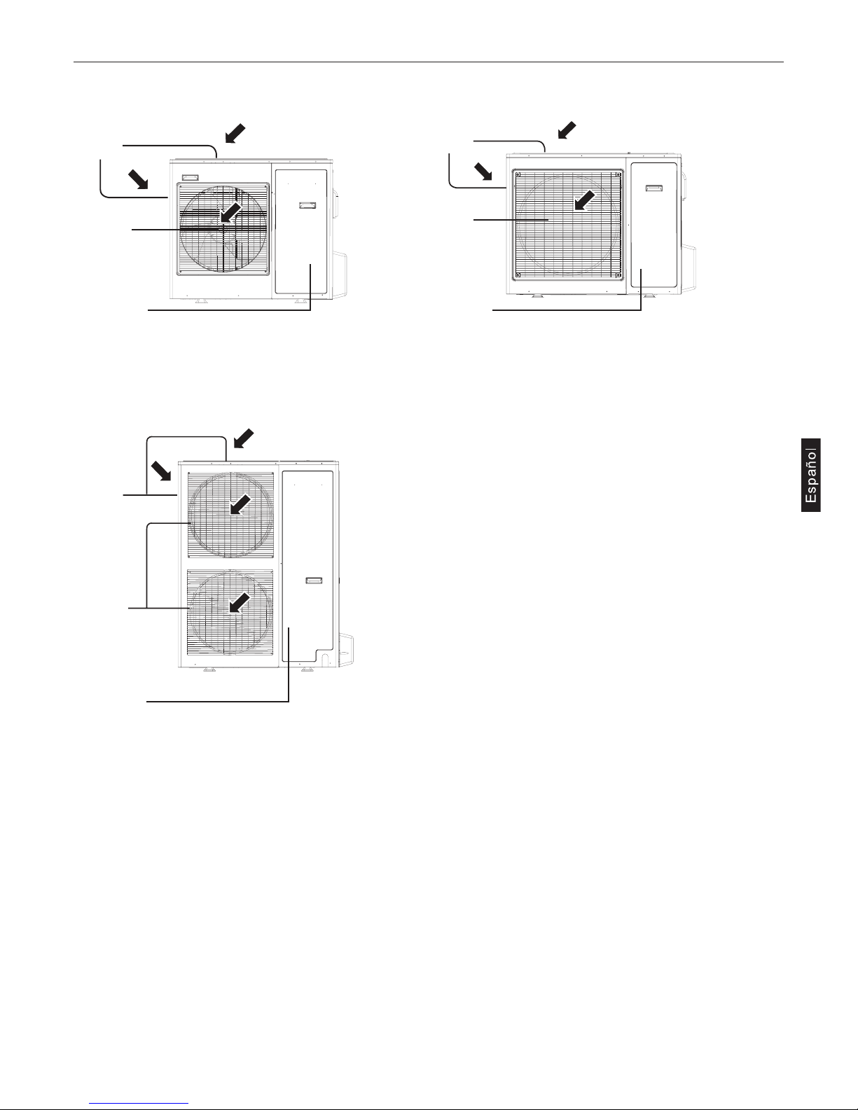
Denominación de los componentes
7
Compresor
(en el interior)
Compresor
(en el interior)
Compresor
(en el interior)
Rejilla
de salida
Rejilla
de salida
Rejilla
de salida
Rejilla de
aspiración
Rejilla de
aspiración
Rejilla de
aspiración
1U28HS1ERA 1U36HS1ERA 1U48LS1ERA 1U48LS1ERB
1U48IS1EAB 1U60IS1ERA 1U60IS1ERB 1U60IS1EAB
AU60NAIESA
1U48LS1EAB
ATENCIÓN
• En caso de sustitución, instale las tuberías nuevas inmediatamente después de haber retirado las viejas para evitar humedad en el
circuito del refrigerante.
• El cloro contenido en algunos tipos de refrigerante como por ejemplo R22 puede causar el deterioro del aceite del aparato.
Los instrumentos para gas R410A deben ser manejados con cuidado, evite el contacto con humedad y polvo.
MATERIAL PARA LAS TUBERÍAS
Use tuberías que cumplan con los estándares locales.
Características de las tuberías de cobre
Grosor radial
Use tubos de cobre desoxidados al fósforo del grosor que se indica en la tabla.
La tabla indica los estándares usados en Japón, haciendo referencia a los datos que figuran elija las tuberías que cumplan con el estándar local. (No use tubos con un grosor radial igual o inferior a 0,7 mm)
Embridado de los tubos
Para aumentar la tensión, el embridador usado para las unidades en R410A es mayor que el usado para las unidades en R22.
Dimensioni flangiatore (mm)
Si se usa un embridador manual por unidad en R410A, deje que sobresalga del tubo entre 1,5 y 2,0 mm.
Tuercas
Para aumentar la resistencia se usan tuercas del tipo que figura en la tabla.
Medidas de las tuercas
La tabla indica los estándares usados en Japón, haciendo referencia a los datos que figuran elija las tuberías que cumplan con el estándar local.
Tubería refrigerante
Presión máxima Refrigerante
3,4MPa R22, R407C
4,15MPa R410A
Medida (mm) Medida (pollici) Grosor radial (mm)
Ø 6,35 1/4’’ 0,8t
Ø 9,52 3/8’’ 0,8t
Ø 12,7 1/2’’ 0,8t
Ø 15,88 5/8’’ 1,0t
Ø 19,05 3/4’’ 1,0t
Medidas embridador Medida Dimensión A R410A
Ø 6,35 1/4’’ 9,1
Ø 9,52 3/8’’ 13,2
Ø 12,7 1/2’’ 16,6
Ø 15,88 5/8’’ 19,7
Ø 19,05 3/4’’ 24,0
A
B
Medidas exteriores tubos Medida Medidas B R410A (Tipo 2)
Ø 6,35 1/4’’ 17,0
Ø 9,52 3/8’’ 22,0
Ø 12,7 1/2’’ 26,0
Ø 15,88 5/8’’ 29,0
Ø 19,05 3/4’’ 36,0
8
 Loading...