

Haier AU482FIBHA, AU48NFIBIA Service Manual
2003.12
MANUAL CODE: SYJS-026-03 rev.0
Haier Group
AC Inverter
Auto-restart function
Group control(if with a group controller)
Auto-changeover
The Outdoor unit can match with max. 8 indoor unit
Electronic expansion valve out to MP3(MP2),more silence
Healthy negative ion generation function(optional)
Features
Service Manual
Commercial Air Conditioning
Home MRV
AU48NFIBIA
AU482FIBHA

CONTENTS
- 1 -
CONTENTS
1. Description of Products & Features
2. Specifications
3. Safety precaution
4. Net dimensions of indoor and outdoor unit
5. Installation instructions
6. Parts and functions
7. Remote controller functions
8. Refrigerant diagram
9. Electrical control functions
10. Diagnostic information(trouble shooting)
11. Electrical data
12. Exploded views and parts lists
13. Perdormance curves
14. Noise level charts
15. Air velocity distribution
Contents
1 DESCRIPTION OF PRODUCTS & FEATURES
l Indoor unit:
Model of indoor unit
A S 09 2 F M B H A
1 2 34 5 6 7 8 9 10
1 Product symbol (A stands for air conditioner)
2 Product mode (S stands for split type air conditioner)
3 , 4 Product specification (09 stands for cooling/heating capacity is 9000BTU/h)
5 Applicable voltage (2 stands for 220-240V/50Hz)
6 Product series (F stands for free combination)
7 Appearance character (M stands for 28 large arc normal air inlet grille 1232084
back frame )
8 Product type (B stands for heat pump type, refrigerant is R407C)
9 Design number (H stands for inverter heat pump air conditioner)
10 Climate type (A stands for T1 climate)
Model of indoor unit
A P 18 2 F A B H A
1 2 3 4 5 6 7 8 9 10
1 Product symbol (A stands for air conditioner)
2 Product mode (P stands for packaged type air conditioner)
3 , 4 Product specification (18 stands for cooling/heating capacity is 18,000BTU)
5 Applicable voltage (2 stands for 220-240V/50Hz)
6 Product series (F stands for free combination)
7 Appearance character (A stands for appearance of inverter packaged type air
conditioner)
8 Product type (B stands for heat pump type, refrigerant is R407C)
9 Design number (H stands for inverter heat pump air conditioner)
10 Climate type (A stands for T1 climate)
l Outdoor unit:
Model of outdoor unit
A U 48 2 F I B H A
1 2 3 4 5 6 7 8 9 10
1 Product symbol (A stands for air conditioner)
2 Product mode (U stands for split type air conditioner outdoor unit)
3 , 4 Product specification (48 stands for cooling/heating capacity is 48,000BTU)
5 Applicable voltage (2 stands for 220-240V/50Hz, N stands for 380~400V/Hz)
6 Product series (F stands for free combination)
7 Appearance character (H stands for 5HP outdoor unit)
8 Product type (B stands for heat pump type, refrigerant is R407C)
9 Design number
10 Climate type (A stands for T1 climate)
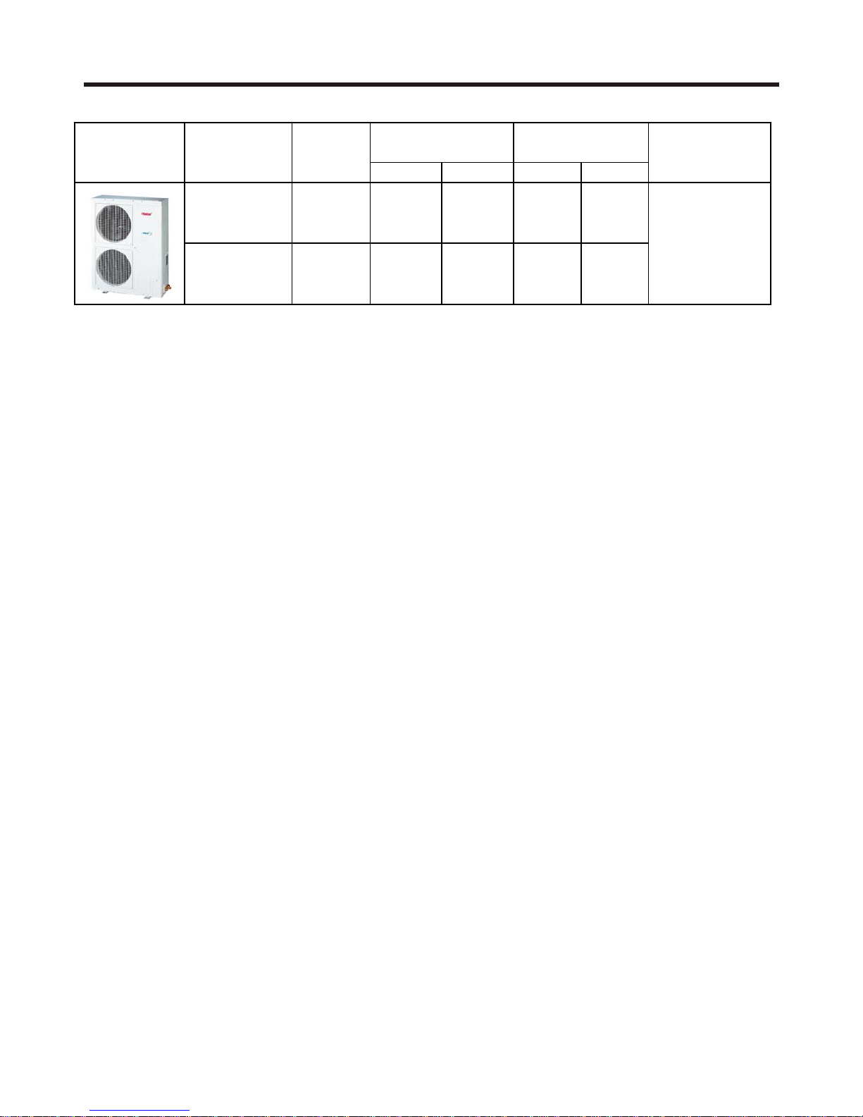
1. Nomenclature
coolin
g
heatin
g
Min. Max
.
AU482FIBHA R407C 48000 61000 2.5 6.5
AU48NFIBIA R407C 48000 61000 2.5 6.5
8
outdoor units
capacity(BTU/h)
connect
ca
p
acity(HP
)
appearance model
refrigeran
t
Max. indoo
r
units can be
connected
indoor units
coolin
g
heatin
g
coolin
g
heatin
g
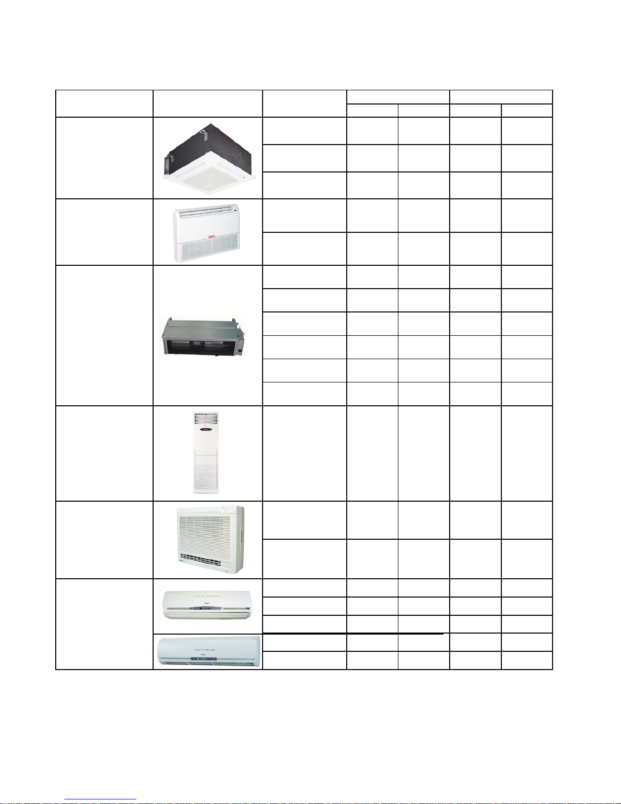
AB092FCBHA
9000 12000 2600 3500
AB142FCBHA
14000 16000 4100 4700
AB182FCBHA
18000 20000 5300 5900
AC142FCBHA
14000 16000 4100 4700
AC182FCBHA
18000 21000 5300 6200
AE072FCBKA
7000 9000 2100 2600
AE092FCBKA
9000 10000 2600 2900
AE122FCBKA
12000 14000 3500 4100
AE142FCBKA
14000 16000 4100 4680
AE182FCBKA
18000 21000 5300 6200
AE242FCBKA
24000 27000 7000 7900
Cabinet
AP182FABHA
18000 21000 5300 6200
AF092FCBHA
9000 11000 2600 3200
AF122FCBHA
12000 13500 3500 4000
AS072FCBHA
7000 7500 2000 2200
AS092FCBHA
9000 10000 2600 2900
AS122FCBHA
12000 14000 3500 4100
AS142FCBHA
14000 16000 4100 4680
AS182FCBHA
18000 21000 5300 6200
Four way cassette
Wall-mounted
Console
Ceiling concealed
Convertible
capacity(BTU/h) capacity(W)
type appearance model
(colorful screen)

4. Character of Products
1) The length of horizontal refrigerant pipe can reach 70m,the total pipe length can reach
100m, the height difference between indoors unit and outdoor unit can reach 50m, the
height difference between indoor units can reach 10m.
2) 1000m super far distance communication between indoor and outdoor units, convenient
control and easy to enlarge the scale of units assembly.
3) Indoor unit can be controlled separately.
4) Equipped with computer-checking interface, conveniently for service work.
5) Far distance sending of refrigerant, and distribute refrigerant intelligently and reasonably
according to the needs of each room, high efficient and energy saving.
6) Display of automatic test of trouble.
7) Healthy negative ion generation function can refresh the air and excite the oxygen,it is optional.
8) The AE and AS indoor units move the indoor electronic expansion valve out to
MP3 (electronic expansion valve box), completely avoid the flow sound of EEV,
extremely lower noise, and realize super-silence running in deed.
9) The ceiling concealed models all have return air box, it will be set back return air
when out of factory. When installation, bottom plate 2 can be removed and installed
on the back, consequently, return air mode has been ransferred to down return
air.
10) In order to remain the best running state of indoor unit, control the refrigerant flow
by MP3 (MP2), so as to realize energy saving for every unit and the most
comfortable operation.
11) The units except for convertible model are all wired controller and remote controller
models.If you want a wired control unit or a remote control unit, please inform us ahead of
schedule.
The unit with remote controller is matched with receive display.
The unit with wired controller equipped with wired controller, can make remote operation on
wired controller with remote controller such as YR-H71, but the remote controller is
additionally purchased.
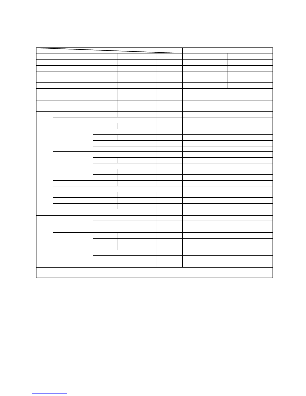
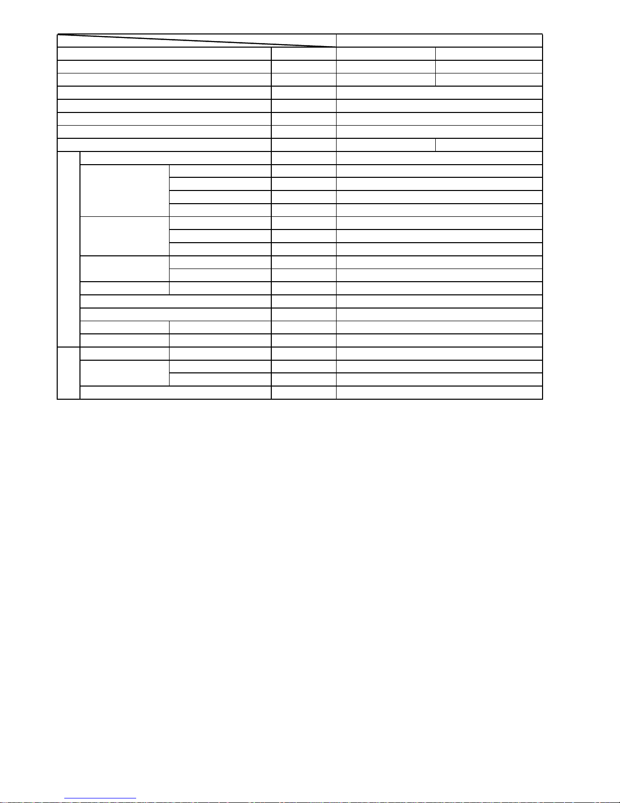
Function
cooling heating
Capacity kW
14000 18000
Capacity BTU/h
48000 61000
W
6500 6000
W
7500 7500
EER or COP W/W
2.15 3.0
Power cabl
e
Power source
N,V,Hz
A / A
Start Current A
Unit model
(
color
)
Model / Manufacture
Type
Type × Number
Speed r/min
Fan motor output power kW
A
ir-flow(H-M-L
)
m³/h
Type / Diameter mm
Total area m²
Temp. scope
℃
External
(L×W×H)
mm×mm×mm
Package
(L×W×H)
mm×mm×mm
Refrigerant control method mm/mm
Volume of Accumulator L
Noise level dB(A)
material of reduce noise
kg / kg
T
yp
e / Charge
g
Recharge quantity g/m
Liquid mm
Gas mm
Connecting Method
m
m
m
Defrosting
Weight (Net / Shipping)
Norminal condition: indoor temperature (cooling): 27 ℃DB/19℃WB, indoor temperature (heating): 20 ℃DB
Outdoor temperature(cooling): 35℃DB/24℃WB, outdoor temperature(heating): 7 ℃DB/6℃WB
φ19.05
flared
Between I.D &O.D
MAX.Dro
p(
indoor&outdoor
)
30
MAX.Piping length
100
Compressor
Fan
Heat exchanger
Dimension
R407C/4200
φ9.52 liquid pipe:65g×actual length,φ6.35
liquid pipe:30g×actual length
φ9.52
PIPING
Refrigerant
Pipe
XPE
120/135
PMV and capillary
auto
3
55
1075X1260X445
7480/6490/4370
TP2M/φ9.52
0.92
item Model
AU482FIBHA
cooling: 34A/42 A heating: 30A/40A
axial flow*2
AU482FIBHA( white)
EEV48FAL1 MITSUBISHIELECTRIC
scroll
7A
Running /Max.Running
Outdoor unit
1PH~,220V,50Hz
MAX.Drop(indoor&indoor
)
10
Total power input
Max. power input
8mm2
H:1060±30; M:920±40; L:620±50
120*2
43-60
948X1125X380
SPECIFICATIONS:
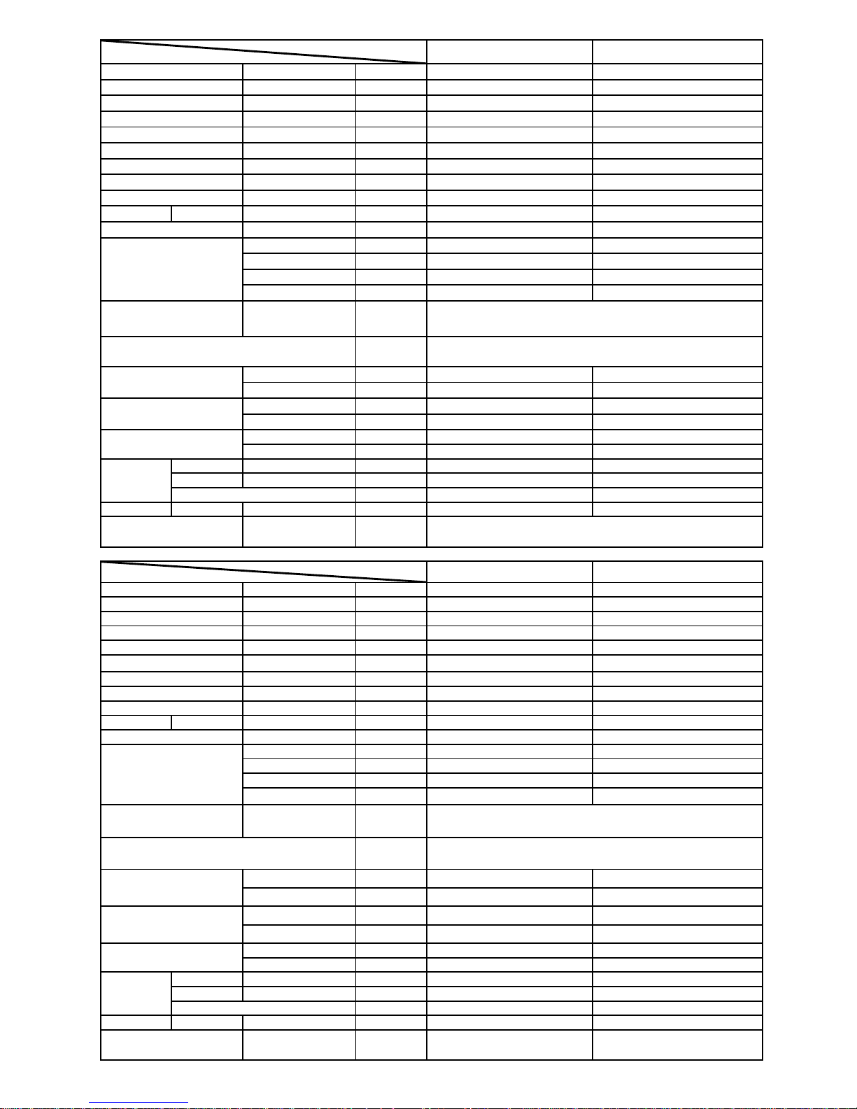
AB092FCBHA AB142FCBHA
Cooling capacity
Btu/h 9000 14000
Heating capacity
Btu/h 12000 16000
Cooling capacity W
2600 4100
Heating capacity W
3500 4700
Dehumidifying capacity
10‐³×m³/h 1.6 2.1
Power source
N,V,Hz 1PH 220V-230V 50HZ 1PH 220V-230V 50HZ
Power consumption W
15 15
Running current A
0.07 0.07
Starting current A
0.2 0.2
Refrigerant
R407C R407C
Noise level(H/M/L) dB(A)
42.6/35.0/31.7 42.6/35.0/31.7
Type × Number
centrifugal fan×1 centrifugal fan×1
Air-flow(H-M-L) m³/h
705/624/511 705/624/511
Fan motor output W
15 15
starting mothod
Relay control Relay control
Heat exchanger
Refrigerant control method
External
mm×mm×mm
570×570×27
6
570×570×27
6
Shipping mm×mm×mm
715×715×361 715×715×361
External
mm×mm×mm
630×630×8
0
630×630×8
0
Shipping mm×mm×mm
685×685×15
0
685×685×15
0
Net kg / kg
26/4.2 26/4.2
Shipping kg / kg
28/6.3 28/6.3
Liquid mm (inch)
6.35
(
1/4"
)
6.35 (1/4"
)
Gas mm (inch)
9.52
(
3/8"
)
12.7 (1/2"
)
Connection method
flared flared
Suited area m2
12~23 17~27
Controller type
AB182FCBHA AC142FCBHA
Cooling capacity
Btu/h 18000 14000
Heating capacity
Btu/h 21000 16000
Cooling capacity W
5300 4100
Heating capacity W
6200 4700
Dehumidifying capacity
10‐³×m³/h 2.1 2.1
Power source
N,V,Hz
1PH 220V-230V 50HZ 1PH 220V-230V 50HZ
Power consumption W
20 70
Running current
A
0.09 0.3
Starting current
A
0.3 0.9
Refrigerant
R407C R407C
Noise level(H/M/L) dB(A)
42.6/35.0/31.7 48/44/38
Type × Number
centrifu
g
al fan×1 centrifugal fan×1
A
ir-flow(H-M-L) m³/h
705/624/511 900/815/704
Fan motor output W
20 70
starting mothod Relay control Relay control
Heat exchanger
Refrigerant control method
External
mm×mm×mm 570×570×276 990×655×199
Shipping
mm×mm×mm 715×715×361 1160×760×310
External
mm×mm×mm 630×630×80 /
Shipping
mm×mm×mm 685×685×150 /
Net kg / kg
26/4.2 30
Shipping kg / kg
28/6.3 39
Liquid mm (inch)
9.52
(
3/8"
)
9.52(3/8"
)
Gas mm (inch)
15.88
(
5/8"
)
15.88(5/8"
)
Connection method
flared flared
Suited area m2
22~33 16~23
Controller type
wired controller or remote
controller
remote controller
Combination of wave cranny radiation fin and copper
pipe
Capillary + Electronic expansion valve
Combination of wave cranny radiation fin and copper
pipe
Capillary + Electronic expansion valve
wired controller or remote controller
Piping
Piping
Item model
Fan
Panel dimension (L×W×
H)
Weight(unit/panel)
Weight(unit/panel)
Dimension (L×W×H)
Fan
Item model
Dimension (L×W×H)
Panel dimension (L×W×
H
)
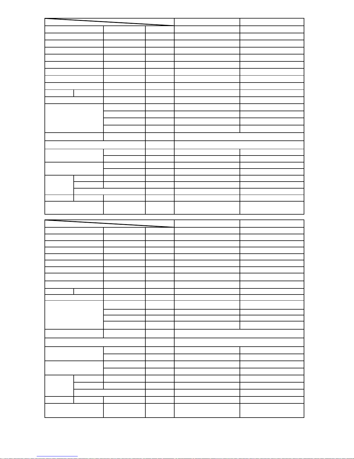
AC182FCBHA AP182FABHA
Cooling capacity
Btu/h
18000 18000
Heating capacity
Btu/h
21000 21000
Cooling capacity W 5300 5300
Heating capacity W 6200 6200
Dehumidifying capacity
10‐³×m³/h
2.1 2.6
Power source
N,V,Hz
1PH 220V-230V 50HZ 1PH 220V-230V 50HZ
Power consumption W 70 100
Running current A 0.3 0.6
Starting current A 0.9 2.0
Refrigerant R407C R407C
Noise level(H/M/L) dB(A) 48/44/38 48/45/39
Type × Number centrifugal fan×1 centrifugal fan×1
Air-flow(H-M-L) m³/h 900/815/704 820/725/630
Fan motor output W 70 70
starting mothod Relay control Relay control
Heat exchanger
Refrigerant control method
External mm×mm×mm
990×655×19
9
1746×500×25
0
Shipping mm×mm×mm
1160×760×31
0
1862×610×40
5
Net kg / kg 30 36
Shipping kg / kg 39 49
Liquid mm (inch)
9.52(3/8") 9.52(3/8")
Gas mm (inch)
15.88(5/8") 15.88(5/8")
Connection method
flared flared
Suited area m2 22~33 23~36
Controller type
remote controller wired controller or remote
controller
AF092FCBHA AF122FCBHA
Cooling capacity
Btu/h
9000 12000
Heating capacity
Btu/h
11000 13500
Cooling capacity W 2600 3500
Heating capacity W 3200 4000
Dehumidifying capacity
10‐³×m³/h
1.6 1.6
Power source
N,V,Hz 1PH 220V-230V 50HZ 1PH 220V-230V 50HZ
Power consumption W
40 40
Running current A 0.2 0.2
Starting current A 0.6 0.6
Refrigerant
R407C R407C
Noise level(H/M/L) dB(A) 37/34/30 37/34/30
Type × Number
cross-flow fan×2 cross-flow fan×2
Air-flow(H-M-L) m³/h 620/530/480 620/530/480
Fan motor output W 20+11 20+11
starting mothod
Relay control Relay control
Heat exchanger
Refrigerant control method
External
mm×mm×mm 783×225×440 783×225×440
Shipping
mm×mm×mm 936×298×533 936×298×533
Net kg / kg 17 17
Shipping kg / kg 17.7 17.7
Liquid mm (inch) 6.35(1/4") 6.35(1/4")
Gas mm (inch) 12.7(1/2") 12.7(1/2")
Connection method flared flared
Suited area m2 12~23 17~27
Controller type
wired controller or remote
controller
wired controller or remote
controller
Combination of wave cranny radiation fin and copper
Capillary + Electronic expansion valve
Combination of wave cranny radiation fin and copper
Capillary + Electronic expansion valve
Piping
Piping
Item model
Fan
Dimension (L×W×H)
Weight(unit/panel)
Item model
Fan
Dimension (L×W×H)
Weight(unit/panel)
——
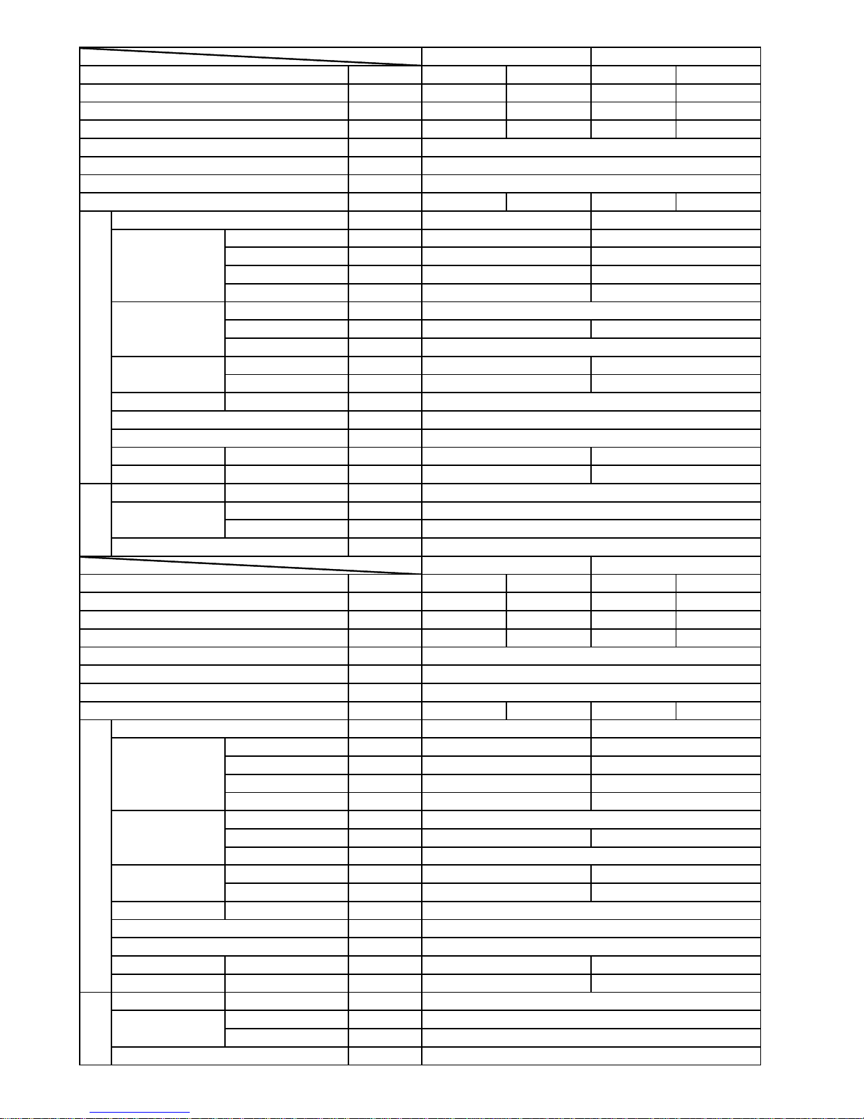
Cooling Heating Cooling Heating
BTU/h
7000 9500 9000 10000
W
2000 2800 2600 3200
10‐³×m³/h
1.0 / 1.0 /
——
——
N, V, Hz
A / A 0.10 0.10 0.10 0.10
——
Type × Number ——
Speed r/min
Motor output power W
Air-flows (H/M/L) m³/h
Type / Diameter mm
Total area m²
Temp. scope
℃
External mm
Package mm
Drainage pipe material, diameter mm
——
——
Noise level H/M/L dB(A)
Weight Net / Shipping kg / kg
Refrigerant
Type ——
Liquid mm
Gas mm
——
——
Cooling Heating Cooling Heating
BTU/h
12000 15000 14000 17000
W
3500 4500 4000 5000
10‐³×m³/h
1.6 / 2.0 /
——
——
N, V, Hz
A / A 0.15 0.15 0.15 0.15
——
Type × Number ——
Speed r/min
Motor output power W
Air-flows (H-M-L) m³/h
Type / Diameter mm
Total area m²
Temp. scope
℃
External mm
Package mm
Drainage pipe material, diameter mm
——
——
Noise level H/M/L dB(A)
Weight Net / Shipping kg / kg
Refrigerant
Type ——
Liquid mm
Gas mm
——
Piping
Pipe
Connecting method
12.7
Flared
R407C
6.35
Dimension
(L×W×H)
cooling: 6~7 / heating: 43~60
PVC, 11.4/16.4
795×197×265 928×197×265
880×315×330 1025×309×330
Indoor unit
Unit model (color)
Fan
Heat exchanger
Dimension
(L×W×H)
Controller type
Refrigerant control
Controller type Phone type infrared
Refrigerant control Capillary tube
25
39/37/30 44/41/38
7.6/10.6 11/14
CROSS×1 CROSS×1
about 0.20 about 0.20
1250/1050/900 1250/1050/900
630/520/410 640/570/450
TP2M / 6.35×0.7
25
3 × 0.75mm
2
Communication cable
1, 220~230, 50
AS122FCBHA (white) AS142FCBHA (white)
Running current
Indoor unit
Unit model (color)
Fan
Heat exchanger
Capacity
Capacity
Dehumidifying capacity
Power source
Power cable
Item Model
AS122FCBHA AS142FCBHA
Function
Flared
Piping
Pipe
Connecting method
R407C
6.35
12.7
7.6/10.6 7.6/10.6
36/33/29 37/35/30
Capillary tube
Phone type infrared
795×197×265 795×197×265
880×315×330 880×315×330
25
520/410/300 600/500/410
PVC, 11.4/16.4
about 0.15 about 0.15
cooling: 6~7 / heating: 43~60
Running current
AS072FCBHA (white) AS092FCBHA (white)
2x
(
0.75~1.25mm2
)
TP2M / 6.35×0.7
CROSS×1 CROSS×1
1050/900/800 1250/1050/900
25
3 ×
(
1.0~1.5mm2
)
Communication cable
Power source 1, 220~230, 50
2x
(
0.75~1.25mm2
)
Capacity
Capacity
Dehumidifying capacity
Power cable
Item Model
AS072FCBHA AS092FCBHA
Function
——
Cooling Heating
BTU/h
18000 20000
W
5200 5800
10‐³×m³/h
——
——
N, V, Hz
A / A 0.10 0.10
——
Type × Number ——
Speed r/min
Motor output power W
Air-flows (H/M/L) m³/h
Type / Diameter mm
Total area m²
Temp. scope
℃
External mm
Package mm
Drainage pipe material, diameter mm
——
——
Noise level H/M/L dB(A)
Weight Net / Shipping kg / kg
Refrigerant
Type ——
Liquid mm
Gas mm
——
Capacity
Dehumidifying capacity 2.0
Power cable
3 × (1.0~1.5mm2 )
Item Model
A
S182FCBH
A
Function
Capacity
Communication cable
2x(0.75~1.25mm2 )
Power source 1, 220~230, 50
Running current
Indoor unit
Unit model (color) AS182FCBHA (white)
Fan CROSS×1
1350/1150/900
25
760/630/560
Heat exchanger
TP2M / 6.35×0.7
about 0.15
cooling: 6~7 / heating: 43~60
Dimension
(L×W×H)
928×197×265
1025×309×330
PVC, 11.4/16.4
Controller type
Phone type infrared
Refrigerant control
Capillary tube
Note:
1.Norminal condition: indoor temperature (cooling): 27℃DB/19℃WB, indoor temperature (heating): 20℃DB
Outdoor temperature(cooling): 35℃DB/24℃WB, outdoor temperature(heating): 7℃DB/6℃WB
2.The noise level is sound pressure level value. And it is measured in the following conditions: 1meter beneath
the unit and in front of the unit 1meter in the anechoic chamber.
44/41/38
11/14
Piping
R407C
Pipe
6.35
12.7
Connecting method
Flared
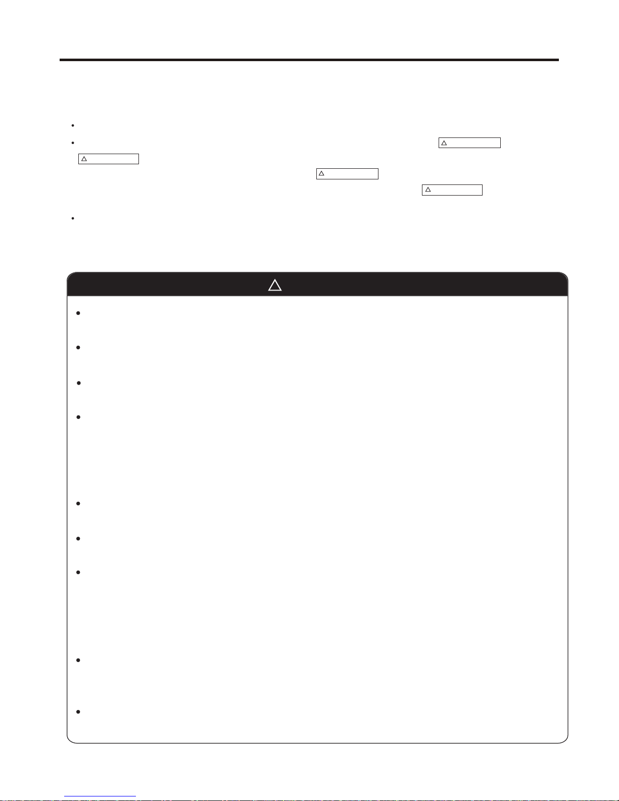
WARNING
CAUTION
WARNING
CAUTION
This system should be applied to places of office, restaurant, residence and the like. Appliaction to inferior
environment such as engineering shop could cause equipment malfunction.
Please entrust installation to either the company which sold you the equipment or to a professional contractor.
Defects from improper installations can be the cause of water leakage, electric shocks and fires.
Execute the installation accurately, based on following the installation manual. Again, improper installations can
result in water leakage, electric shocks and fires.
When a large air-conditioning system is installed to a small room, it is necessary to have a prior planned
countermeasure for the rare case of a refrigerant leakage, to prevent the exceeding of threshold concentration.
In regards to preparing this countermeasure, consult with the company from which you purchased the equipment,
and make the installation accordingly. In the rare event that a refrigerant leakage and exceeding of threshold
concentration does occur,there is the danger of a resultant oxygen deficiency accident.
For installation, confirm that the installation site can sufficiently support heavy weight. When strength is insufficient,
injury can result from a falling of the unit.
Execute the prescribed installation construction to prepare for earthquakes and the strong winds of typhoons and
hurricanes, etc. Improper installations can result in accidents due to a violent falling over of the unit.
For electrical work, please see that a licensed electrician executes the work while following the safety standards
related to electrical equipment, and local regulations as well as the installation instructions, and that only exclusive
use circuits are used.
Insufficient power source circuit capacity and defective installment execution can be the cause of electric shocks and
fires.
Accurately connect wiring using the proper cable, and insure that the external force of the cable is not conducted to
the terminal connection part, through properly securing it. Improper connection or securing can result in heat
generation or fire.
Take care that wiring does not rise upward, and accurately install the lid/service panel. Its improper installation can
also result in heat generation or fire.
WARNING
In either case, important safety related information is indicated, so by all means, properly observe all that is mentioned.
After completing the installation, along with confirming that no abnormalities were seen from the operation tests, please
explain operating methods as well as maintenance methods to the user (customer) of this equipment, based on the owner's
manual.
Moreover, ask the customer to keep this sheet together with the owner's manual.
Please read these "Safety Precautions" first then accurately execute the installation work.
Though the precautionary points indicated herein are divided under two headings, and
those points which are related to the strong possibility of an installation done in error
resulting in death or serious injury are listed in the section. However, there is also a
possibility of serious consequences in relationship to the points listed in the section as well.
- 10 -
SAFETY PRECAUTIONS
3 SAFETY PRECAUTIONS
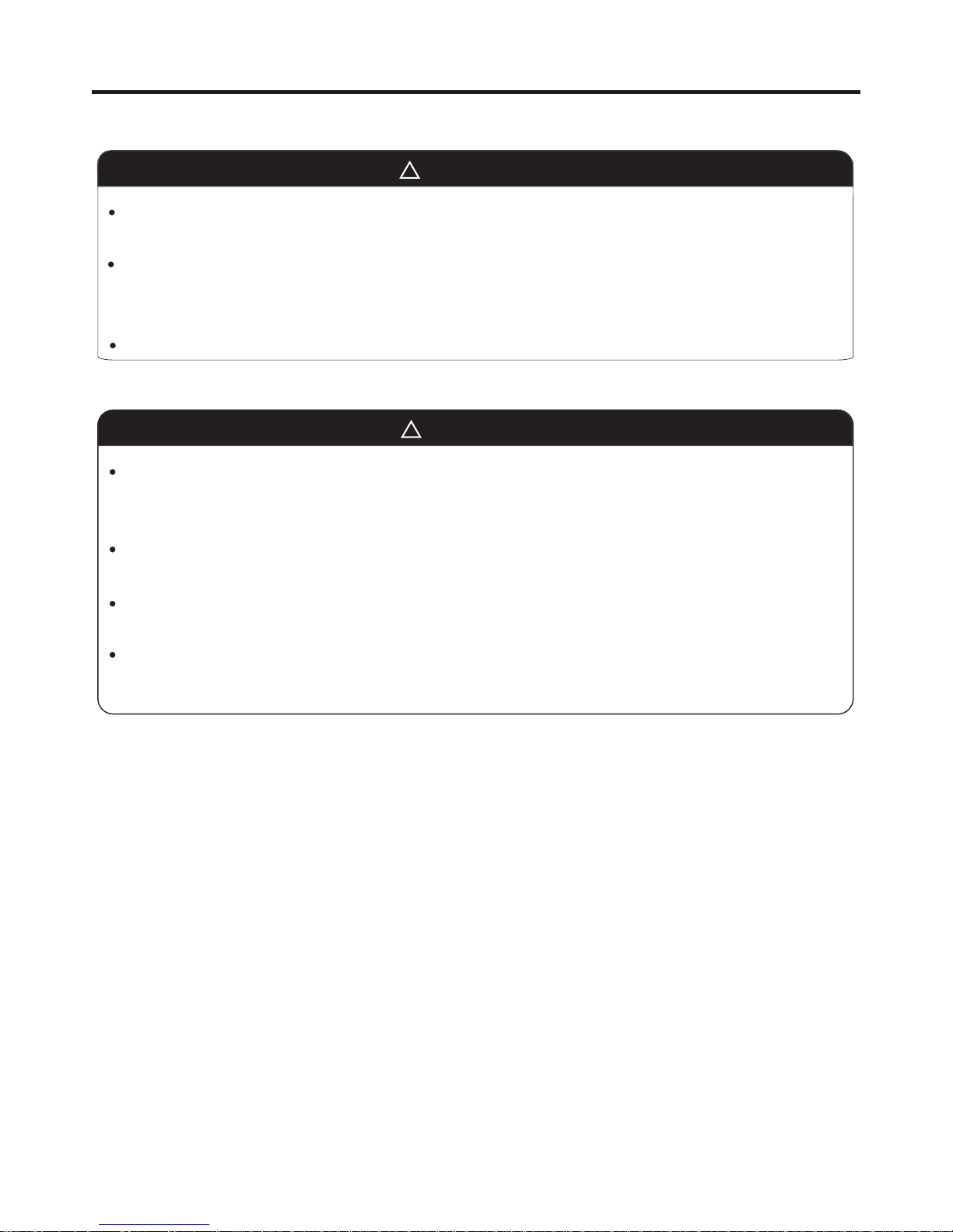
When setting up or moving the location of the air conditioner, do not mix air etc. or anything other than the designated
refrigerant (please see nameplate) within the refrigeration cycle.
Rupture and injury caused by abnormal high pressure can result from such mixing.
Always use accessory parts and authorized parts for installation construction. Using parts not authorized by this
company can result in water leakage, electric shock, fire and refigerant leakage.
The position of indoor unit must be above the floor 2.5m.
WARNING
Execute proper grounding. Do not connect the ground wire to a gas pipe, water pipe, lightening rod or a telephone
ground wire.
Improper placement of ground wires can result in electric shock.
The installation of an earth leakage breaker is necessary depending on the established location of the unit. Not
installing an earth leakage breaker may result in electric shock.
Do not install the unit where there is a concern about leakage of combustible gas.
The rare event of leaked gas collecting around the unit could result in an outbreak of fire.
For the drain pipe, follow the installation manual to insure that it allows proper drainage and thermally insulate it to
prevent condensation. Inadequate plumbing can result in water leakage and water damage to interior items.
CAUTION
- 11 -
SAFETY PRECAUTIONS
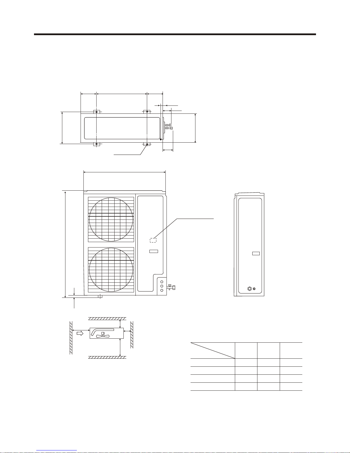
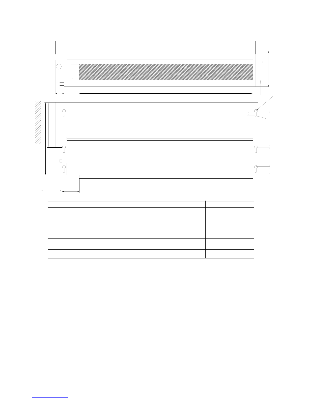
Note : (1). Fix the parts with screws
(2).Don't intake the strong wind directly
to the outlet air-flow hole.
(3).A one meter distance should be
kept from the unit top
(4).Don't block the surroundings of the unit with sundries
Installation Servicing Space(at Least)
Unit:mm
Installation
I
300
100
0
0
150
0
500
100
0
II III
Dimension
L1
Leave space Leave space
Leave space
L2
L3
L4
190 190
30
52
88
Screw Hole
(M10)
580
948
340
380
1125
25
L1
L2
L3
L4
Back Air-flow Hole
Back Airflow Hole
Outlet Air-flow Hole
Repairing Space
Net dimensions of indoor and outdoor
A. model: AU48-
Power wiring Terminal
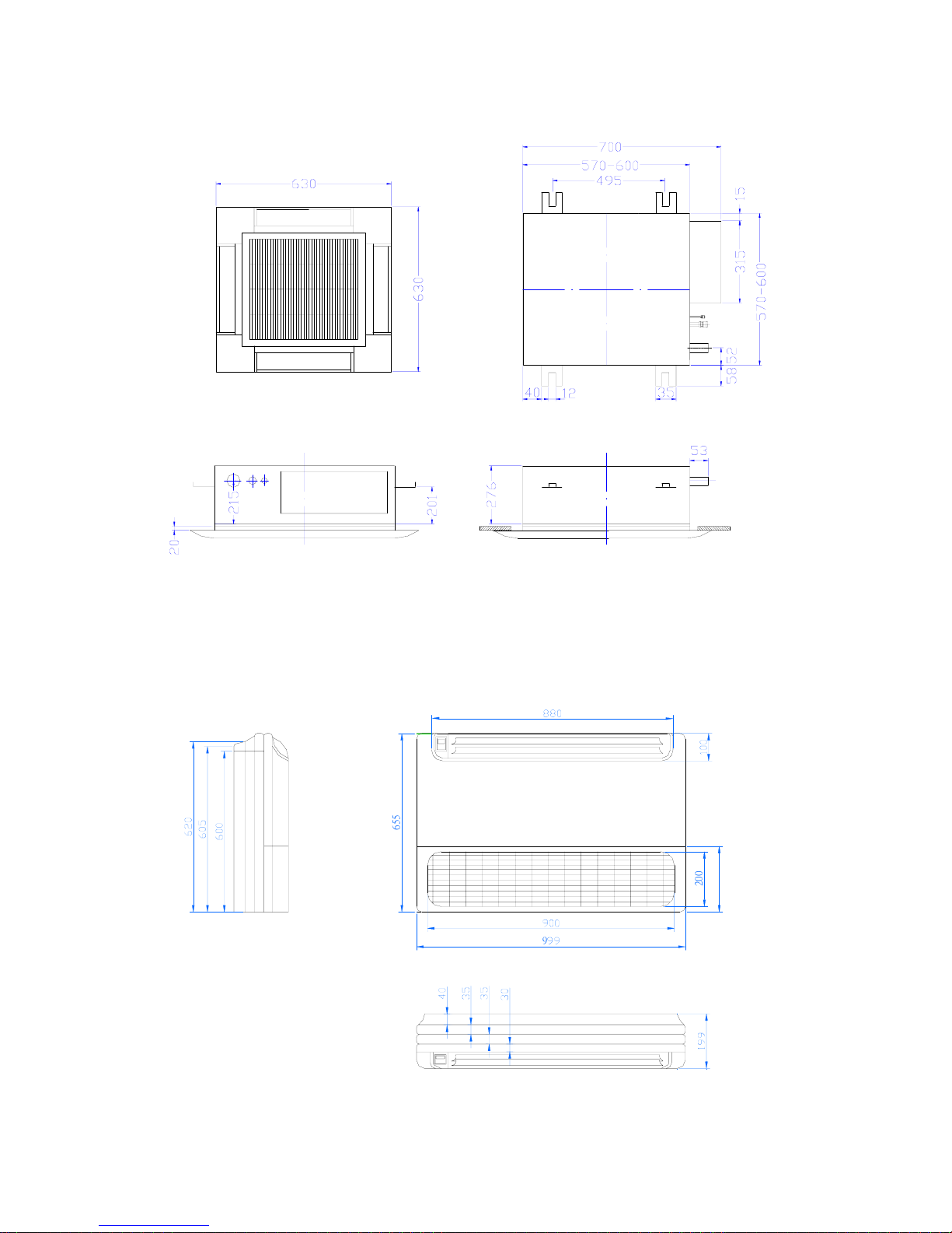
Model: cassette type
6
5
5
240
2
0
0
9
Model: convertible type
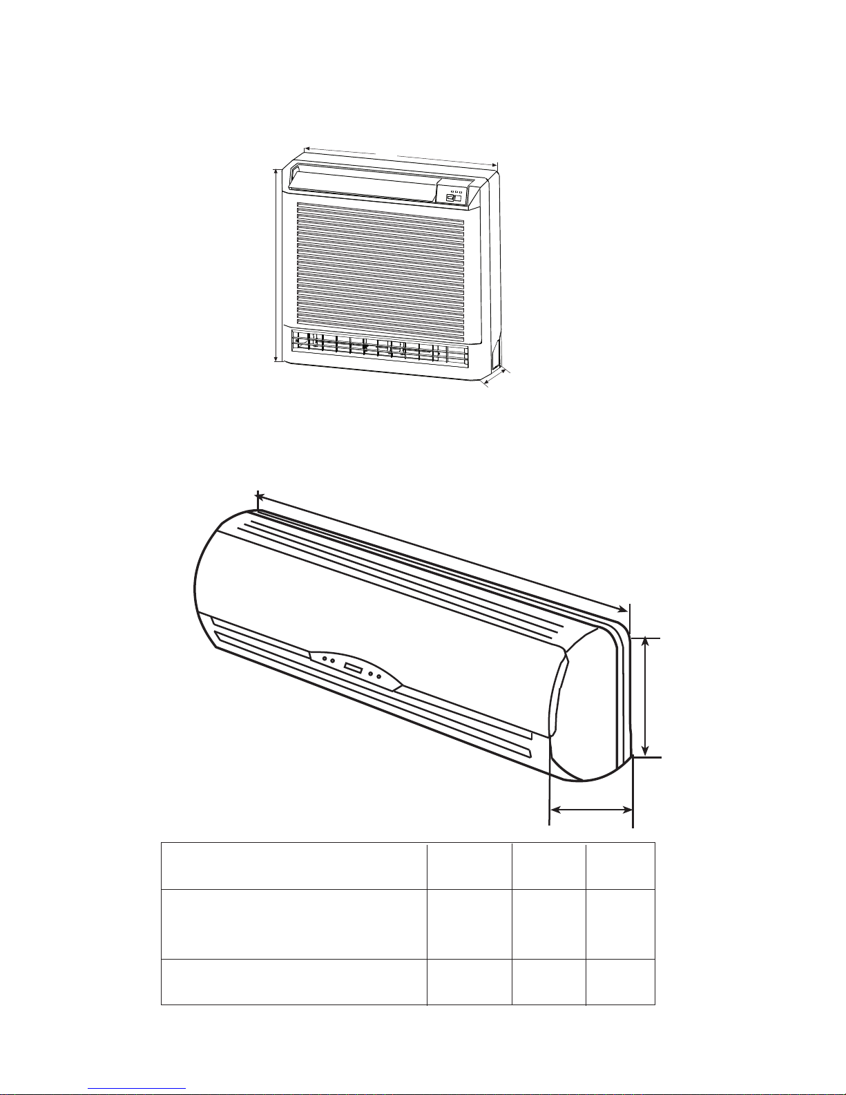
Model: CONSOLE TYPE
783
440
225
Model: WALL MOUNTED TYPE
a
b
c
Fresh air conditioner
Haier
model
a
b c
AS072FCBHA AS092FCBHA
AS122FCBHA
AS142FCBHA AS182FCBHA
795
265
197
197
265
928
Model: ceiling concealed
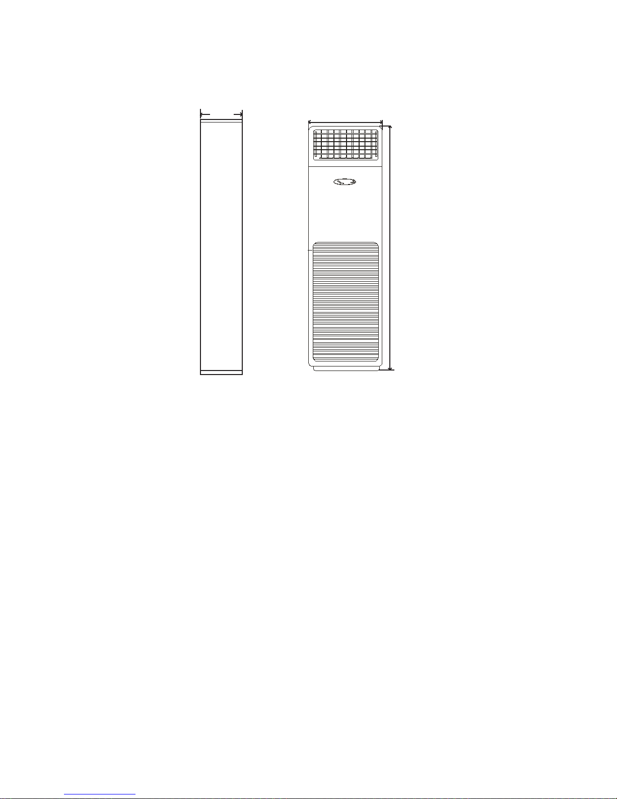
Model: AP182FABHA
500
250
OVER 250
93
1
0
0
1
2
2
5
5
2
2
5
2
2
5
R
5
R
1
0
3
0
2
5
2
5
54
2
4
0
C
b
a
unit model
abc
AE072FCBKA
AE092FCBKA
615
650
452
452
704
800
AE122FCBKA
AE142FCBKA
AE242FCBKA
990
1350
452
858
1020
452
AE182FCBKA
5
Model: AP182FABHA
500
1746
250

9.52
6.35
12.7
9.52
75
12.7
9.52
9.52
12.7
15.88
12.7
15.9
9.52
15.88
9.52
12.7
75
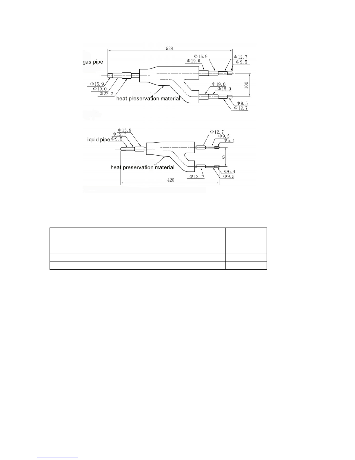
model: FQG-B120
<gas side>
<liquid side>
heat preservation
material
heat preservation
material
Dimension is the out diameter connecting to the tubing.
5 INSTALLATION STRUCTION
5.1 Piping dimensions charts
5.2 Y-shape manifold pipe
model
mm inch mm inch
AU48 9.52 3/8" 19.05 3/4"
AB09 6.35 1/4" 12.7 1/2"
AB14 6.35 1/4" 12.7 1/2"
AB18 6.35 1/4" 12.7 1/2"
AC14 9.52 3/8" 15.88 5/8"
AC18 9.52 3/8" 15.88 5/8"
AE07 6.35 1/4" 9.52 3/8"
AE09 6.35 1/4" 9.52 3/8"
AE12 6.35 1/4" 12.7 1/2"
AE14 6.35 1/4" 12.7 1/2"
AE18 9.52 3/8" 15.88 5/8"
AE24 9.52 3/8" 15.88 5/8"
AF09 6.35 1/4" 12.7 1/2"
AF12 6.35 1/4" 12.7 1/2"
AP18 9.52 3/8" 15.88 5/8"
AS07 6.35 1/4" 9.52 3/8"
AS09 6.35 1/4" 9.52 3/8"
AS12 6.35 1/4" 12.7 1/2"
AS14 6.35 1/4" 12.7 1/2"
AS18 9.52 3/8" 15.88 5/8"
liquid pipe gas pipe
gas pipe
heat preservation material
liquid pipe
heat preservation material
FQG-B180
Refrigerant pipes between manifold pipes
Total refrigerating amount of indoor unit
g
roup after the manifold pipe
Gas side Liquid side
Less than 38220Btu/h 15.9 9.52
38220~61157Btu/h 19.05 9.52
61157~126137Btu/h 25.4 12.7
Note: 1. Y-shape manifold pipe can be placed in horizontal or vertical
direction
2. The manifold pipes must be welded with hard-solder
3. Pay attention to cut off the unnecessary part from its middle
parts of each joint, and to remove burr.
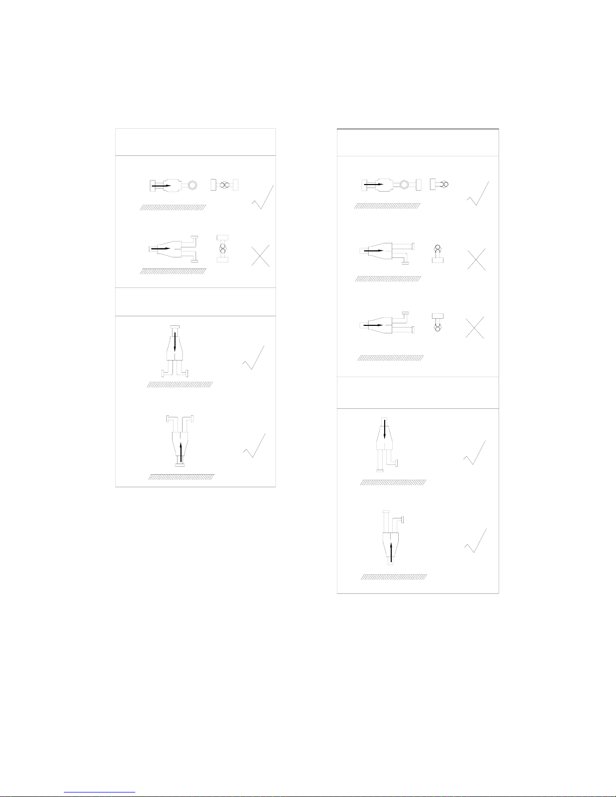
In the file, the figure marked with "√" is permitted, and the figure marked with "×" is prohibited.
You can confirm the position according to the actual condition.
The refrigerant flow direction is always from the collective side to the divided side.
vertical
floor surface
floor surface
floor surface
floor surface
horizontal
floor surface
floor surface
floor surface
floor surface
floor surface
vertical
horizontal
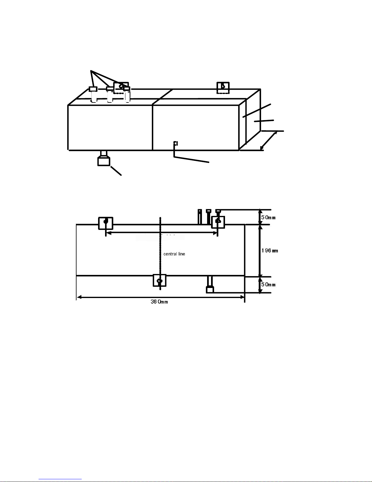
Connect with indoor liquid pipe
Connect with outdoor liquid pipe
Bottom
Cover
Fetch out the power line and the connecting line.
Pay attention to fix firmly with wiring clamp.
1 2 3
80mm
MP3、MP2 Electronic Expansion Valve Box figure:
MP3、MP2 installation dimension:
MP3(MP2)installation procedure:
1、Installation of MP3(MP2)can be used for CEILING CONCEALED MODEL
A、Piping connection
a、When connecting with indoor unit,refrigerant pipe and the connection wire must be
corresponding with the code(A、B、C…) on the device.
NOTE: When using two or more than two MP3 devices (need two or more than two
MP3 devices on connecting more than three indoor units), MUST mark definitely
Room code of connected indoor unit on the MP3 label, so as to air conditioner
maintain conveniently.
b 、 When connecting indoor unit, firstly please weld MP3 with the corresponding
contribution pipe in the accessories table, then connect MP3 with corresponding indoor
connection pipe.
c、MP3 can only be connected with liquid pipe of the unit, the gas pipe connection is the
same as the old ceiling concealed model.
B、MP3(MP2) device installation position
a、MP3(MP2) device should be counted on the vertical wall, maintenance cover panel
must be to the outer, and open a maintenance door over 600mm out of the panel.
b、Indoor distribution pipe must be fetched out from up of MP3 to any direction.
c、Lean must be in the range of ±5°.
C、Wiring connection:
a、Power wiring、communication wiring of the same indoor unit must correspond with its
connection pipe、electronic expansion valve (refer to the wiring diagram on the indoor
electric box cover and MP3).
b、After wiring connection, the wiring must be fixed firmly with wire clip.
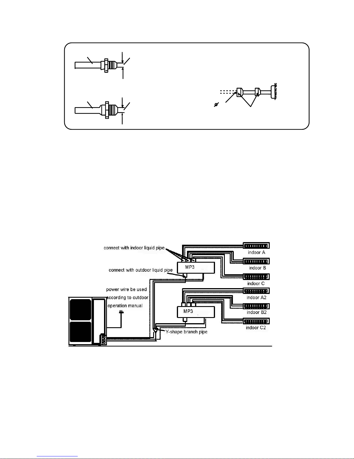
2、MP3(MP2) refrigerant circuit can be used for ceiling concealed model (only show
out liquid pipe connection)
Note: Cutoff the pipe of standard
accessories according to indoor
distribute pipe diameter, then connect it
with MP3
Outer diameter 6.35mm Inner diameter 9.52mm
.
Inner
diameter
6.35mm
Wax sealed
9.52
C
onnect w
ith pi
pe diameter 9.52mm on
li
q
uid side
For example:
Outer diameter
6.35mm

TOTAL
COOLING
CAPACITY
TOTAL
HEATING
CAPACITY
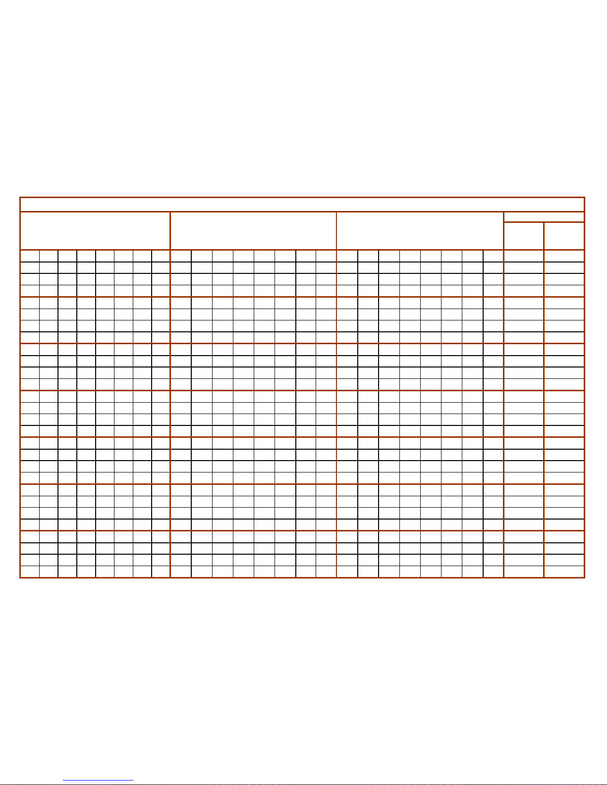
18 18 18 18 18 18 18 18 1.75 1.75 1.75 1.75 1.75 1.75 1.75 1.75 2.00 2.00 2.00 2.00 2.00 2.00 2.00 2.00 14.00 16.00
18 18 18 18 18 18 71 1.41 1.41 1.41 1.41 1.41 1.41 5.54 1.61 1.61 1.61 1.61 1.61 1.61 6.35 14.00 16.00
18 18 18 18 18 18 60 1.50 1.50 1.50 1.50 1.50 1.50 5.00 1.71 1.71 1.71 1.71 1.71 1.71 5.71 14.00 16.00
18 18 18 18 18 18 56 1.54 1.54 1.54 1.54 1.54 1.54 4.76 1.76 1.76 1.76 1.76 1.76 1.76 5.46 14.00 16.00
18 18 18 18 18 18 56 18 1.38 1.38 1.38 1.38 1.38 1.38 4.34 1.38 1.58 1.58 1.58 1.58 1.58 1.58 4.92 1.58 14.00 16.00
18 18 18 18 18 18 50 1.59 1.59 1.59 1.59 1.59 1.59 4.46 1.82 1.82 1.82 1.82 1.82 1.82 5.06 14.00 16.00
18 18 18 18 18 18 50 18 1.43 1.43 1.43 1.43 1.43 1.43 3.99 1.43 1.64 1.64 1.64 1.64 1.64 1.64 4.55 1.64 14.00 16.00
18 18 18 18 18 18 40 1.70 1.70 1.70 1.70 1.70 1.70 3.80 1.95 1.95 1.95 1.95 1.95 1.95 4.32 14.00 16.00
18 18 18 18 18 18 40 18 1.52 1.52 1.52 1.52 1.52 1.52 3.36 1.52 1.73 1.73 1.73 1.73 1.73 1.73 3.86 1.73 14.00 16.00
18 18 18 18 18 18 32 1.80 1.80 1.80 1.80 1.80 1.80 3.20 2.06 2.06 2.06 2.06 2.06 2.06 3.66 14.00 16.00
18 18 18 18 18 18 32 18 1.59 1.59 1.59 1.59 1.59 1.59 2.87 1.59 1.82 1.82 1.82 1.82 1.82 1.82 3.24 1.82 14.00 16.00
18 18 18 18 18 18 25 1.89 1.89 1.89 1.89 1.89 1.89 2.66 2.17 2.17 2.17 2.17 2.17 2.17 3.01 14.00 16.00
18 18 18 18 18 18 25 18 1.67 1.67 1.67 1.67 1.67 1.67 2.31 1.67 1.91 1.91 1.91 1.91 1.91 1.91 2.65 1.91 14.00 16.00
18 18 18 18 18 18 40 1.70 1.70 1.70 1.70 1.70 1.70 3.80 1.95 1.95 1.95 1.95 1.95 1.95 4.32 14.00 16.00
18 18 18 18 18 18 40 32 1.40 1.40 1.40 1.40 1.40 1.40 3.11 2.49 1.60 1.60 1.60 1.60 1.60 1.60 3.56 2.84 14.00 16.00
18 18 18 18 18 18 40 25 1.46 1.46 1.46 1.46 1.46 1.46 3.24 2.00 1.66 1.66 1.66 1.66 1.66 1.66 3.70 2.31 14.00 16.00
18 18 18 18 18 18 32 25 1.53 1.53 1.53 1.53 1.53 1.53 2.72 2.10 1.75 1.75 1.75 1.75 1.75 1.75 3.10 2.42 14.00 16.00
18 18 18 18 18 18 32 1.80 1.80 1.80 1.80 1.80 1.80 3.20 2.06 2.06 2.06 2.06 2.06 2.06 3.66 14.00 16.00
18 18 18 18 18 18 25 25 1.59 1.59 1.59 1.59 1.59 1.59 2.23 2.23 1.82 1.82 1.82 1.82 1.82 1.82 2.53 2.53 14.00 16.00
18 18 18 18 18 18 25 1.89 1.89 1.89 1.89 1.89 1.89 2.66 2.17 2.17 2.17 2.17 2.17 2.17 3.01 14.00 16.00
18 18 18 18 18 18 18 2.00 2.00 2.00 2.00 2.00 2.00 2.00 2.29 2.29 2.29 2.29 2.29 2.29 2.29 14.00 16.00
18 18 18 18 18 71 1.57 1.57 1.57 1.57 1.57 6.15 1.79 1.79 1.79 1.79 1.79 7.06 14.00 16.00
18 18 18 18 18 60 25 1.44 1.44 1.44 1.44 1.44 4.80 2.00 1.65 1.65 1.65 1.65 1.65 5.49 2.29 14.00 16.00
18 18 18 18 18 60 1.68 1.68 1.68 1.68 1.68 5.60 1.92 1.92 1.92 1.92 1.92 6.40 14.00 16.00
18 18 18 18 18 56 32 1.42 1.42 1.42 1.42 1.42 4.40 2.50 1.62 1.62 1.62 1.62 1.62 5.03 2.88 14.00 16.00
18 18 18 18 18 56 25 1.47 1.47 1.47 1.47 1.47 4.58 2.07 1.68 1.68 1.68 1.68 1.68 5.24 2.34 14.00 16.00
18 18 18 18 18 56 1.73 1.73 1.73 1.73 1.73 5.35 1.97 1.97 1.97 1.97 1.97 6.14 14.00 16.00
18 18 18 18 18 50 40 1.40 1.40 1.40 1.40 1.40 3.89 3.11 1.60 1.60 1.60 1.60 1.60 4.44 3.56 14.00 16.00
ADMISSIBLE COMBINATION EXAMPLES OF MULTIFLEX INVERTER
REAL COOLING CAPACITY
(OF EACH UNIT IN COMBINATION)
Kw
kW
Type of INDOOR UNITS CIRCUIT (×100W)
REAL HEATING CAPACITY
(OF EACH UNIT IN COMBINATION)
kW

TOTAL
COOLING
CAPACITY
TOTAL
HEATING
CAPACITY
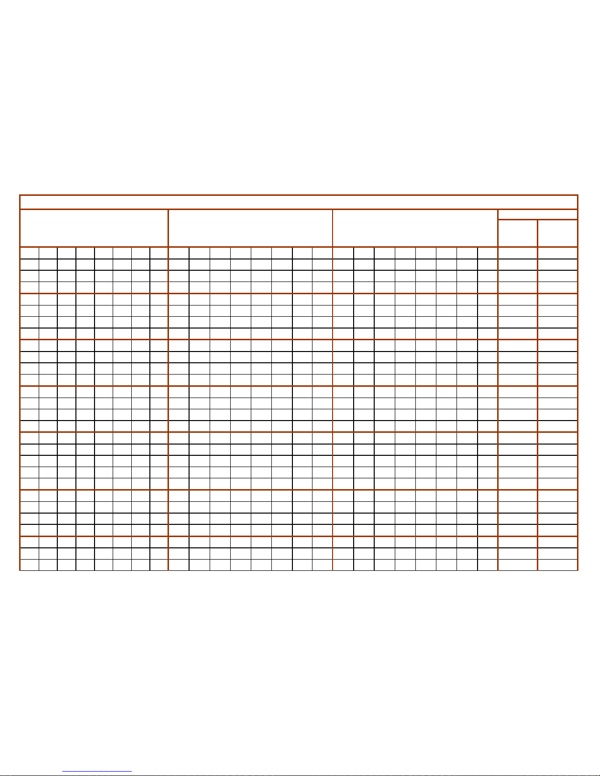
ADMISSIBLE COMBINATION EXAMPLES OF MULTIFLEX INVERTER
REAL COOLING CAPACITY
(OF EACH UNIT IN COMBINATION)
Kw
kW
Type of INDOOR UNITS CIRCUIT (×100W)
REAL HEATING CAPACITY
(OF EACH UNIT IN COMBINATION)
kW
18 18 18 18 18 50 32 1.46 1.46 1.46 1.46 1.46 4.07 2.63 1.67 1.67 1.67 1.67 1.67 4.65 2.98 14.00 16.00
18 18 18 18 18 50 25 1.53 1.53 1.53 1.53 1.53 4.24 2.11 1.75 1.75 1.75 1.75 1.75 4.85 2.42 14.00 16.00
18 18 18 18 18 40 50 1.40 1.40 1.40 1.40 1.40 3.11 3.89 1.60 1.60 1.60 1.60 1.60 3.56 4.44 14.00 16.00
18 18 18 18 18 40 40 1.48 1.48 1.48 1.48 1.48 3.29 3.29 1.69 1.69 1.69 1.69 1.69 3.76 3.76 14.00 16.00
18 18 18 18 18 40 32 1.56 1.56 1.56 1.56 1.56 3.46 2.74 1.78 1.78 1.78 1.78 1.78 3.95 3.16 14.00 16.00
18 18 18 18 18 40 25 1.63 1.63 1.63 1.63 1.63 3.61 2.24 1.86 1.86 1.86 1.86 1.86 4.13 2.58 14.00 16.00
18 18 18 18 18 40 1.94 1.94 1.94 1.94 1.94 4.31 2.22 2.22 2.22 2.22 2.22 4.92 14.00 16.00
18 18 18 18 18 32 32 1.64 1.64 1.64 1.64 1.64 2.91 2.91 1.87 1.87 1.87 1.87 1.87 3.32 3.32 14.00 16.00
18 18 18 18 18 32 25 1.71 1.71 1.71 1.71 1.71 3.05 2.40 1.96 1.96 1.96 1.96 1.96 3.48 2.72 14.00 16.00
18 18 18 18 18 32 2.06 2.06 2.06 2.06 2.06 3.70 2.34 2.34 2.34 2.34 2.34 4.16 14.00 16.00
18 18 18 18 18 25 25 1.80 1.80 1.80 1.80 1.80 2.50 2.50 2.06 2.06 2.06 2.06 2.06 2.86 2.86 14.00 16.00
18 18 18 18 18 18 2.33 2.33 2.33 2.33 2.33 2.33 2.66 2.66 2.66 2.66 2.66 2.66 14.00 16.00
18 18 18 32 40 56 1.38 1.38 1.38 2.46 3.08 4.31 1.58 1.58 1.58 2.81 3.52 4.92 14.00 16.00
18 18 18 32 40 50 1.43 1.43 1.43 2.55 3.18 3.98 1.64 1.64 1.64 2.91 3.64 4.55 14.00 16.00
18 18 18 32 40 40 1.52 1.52 1.52 2.70 3.37 3.37 1.73 1.73 1.73 3.08 3.86 3.86 14.00 16.00
18 18 18 32 40 32 1.59 1.59 1.59 2.84 3.55 2.84 1.82 1.82 1.82 3.24 4.05 3.24 14.00 16.00
18 18 18 32 40 25 1.67 1.67 1.67 2.97 3.71 2.31 1.91 1.91 1.91 3.39 4.24 2.65 14.00 16.00
18 18 18 32 40 18 1.75 1.75 1.75 3.11 3.89 1.75 2.00 2.00 2.00 3.56 4.44 2.00 14.00 16.00
18 18 18 32 40 2.00 2.00 2.00 3.56 4.44 2.29 2.29 2.29 4.06 5.08 14.00 16.00
18 18 18 32 32 60 1.42 1.42 1.42 2.51 2.51 4.72 1.62 1.62 1.62 2.88 2.88 5.39 14.00 16.00
18 18 18 32 32 50 1.50 1.50 1.50 2.67 2.67 4.16 1.71 1.71 1.71 3.05 3.05 4.76 14.00 16.00
18 18 18 32 32 40 1.59 1.59 1.59 2.84 2.84 3.55 1.82 1.82 1.82 3.24 3.24 4.05 14.00 16.00
18 18 18 32 32 32 1.68 1.68 1.68 2.99 2.99 2.99 1.92 1.92 1.92 3.41 3.41 3.41 14.00 16.00
18 18 18 32 32 25 1.76 1.76 1.76 3.13 3.13 2.46 2.01 2.01 2.01 3.58 3.58 2.80 14.00 16.00
18 18 18 32 32 18 1.85 1.85 1.85 3.29 3.29 1.85 2.12 2.12 2.12 3.76 3.76 2.12 14.00 16.00
18 18 18 32 32 2.14 2.14 2.14 3.80 3.80 2.44 2.44 2.44 4.34 4.34 14.00 16.00
18 18 18 32 25 71 1.38 1.38 1.38 2.46 1.92 5.46 1.58 1.58 1.58 2.81 2.20 6.24 14.00 16.00
18 18 18 32 25 60 1.47 1.47 1.47 2.62 2.05 4.91 1.68 1.68 1.68 2.99 2.34 5.61 14.00 16.00

TOTAL
COOLING
CAPACITY
TOTAL
HEATING
CAPACITY
ADMISSIBLE COMBINATION EXAMPLES OF MULTIFLEX INVERTER
REAL COOLING CAPACITY
(OF EACH UNIT IN COMBINATION)
Kw
kW
Type of INDOOR UNITS CIRCUIT (×100W)
REAL HEATING CAPACITY
(OF EACH UNIT IN COMBINATION)
kW
18 18 18 32 25 56 1.51 1.51 1.51 2.68 2.10 4.69 1.72 1.72 1.72 3.07 2.40 5.37 14.00 16.00
18 18 18 32 25 50 1.57 1.57 1.57 2.78 2.17 4.35 1.79 1.79 1.79 3.18 2.48 4.97 14.00 16.00
18 18 18 32 25 40 1.67 1.67 1.67 2.97 2.32 3.71 1.91 1.91 1.91 3.39 2.65 4.24 14.00 16.00
18 18 18 32 25 25 1.85 1.85 1.85 3.29 2.57 2.57 2.12 2.12 2.12 3.76 2.94 2.94 14.00 16.00
18 18 18 32 25 18 1.95 1.95 1.95 3.47 2.71 1.95 2.23 2.23 2.23 3.97 3.10 2.23 14.00 16.00
18 18 18 32 25 2.27 2.27 2.27 4.04 3.15 2.59 2.59 2.59 4.61 3.60 14.00 16.00
18 18 18 32 71 18 1.44 1.44 1.44 2.56 5.68 1.44 1.65 1.65 1.65 2.93 6.49 1.65 14.00 16.00
18 18 18 32 71 1.61 1.61 1.61 2.85 6.33 1.83 1.83 1.83 3.26 7.24 14.00 16.00
18 18 18 32 60 18 1.54 1.54 1.54 2.73 5.12 1.54 1.76 1.76 1.76 3.12 5.85 1.76 14.00 16.00
18 18 18 32 60 1.73 1.73 1.73 3.07 5.75 1.97 1.97 1.97 3.51 6.58 14.00 16.00
18 18 18 32 56 18 1.58 1.58 1.58 2.80 4.90 1.58 1.80 1.80 1.80 3.20 5.60 1.80 14.00 16.00
18 18 18 32 56 1.77 1.77 1.77 3.15 5.52 2.03 2.03 2.03 3.61 6.31 14.00 16.00
18 18 18 32 50 18 1.64 1.64 1.64 2.91 4.55 1.64 1.87 1.87 1.87 3.32 5.19 1.87 14.00 16.00
18 18 18 32 50 1.85 1.85 1.85 3.29 5.15 2.12 2.12 2.12 3.76 5.88 14.00 16.00
18 18 18 32 40 18 1.75 1.75 1.75 3.11 3.89 1.75 2.00 2.00 2.00 3.56 4.44 2.00 14.00 16.00
18 18 18 32 40 2.00 2.00 2.00 3.56 4.44 2.29 2.29 2.29 4.06 5.08 14.00 16.00
18 18 18 25 71 1.68 1.68 1.68 2.33 6.63 1.92 1.92 1.92 2.67 7.57 14.00 16.00
18 18 18 25 60 1.81 1.81 1.81 2.52 6.04 2.07 2.07 2.07 2.88 6.91 14.00 16.00
18 18 18 25 56 1.87 1.87 1.87 2.59 5.81 2.13 2.13 2.13 2.96 6.64 14.00 16.00
18 18 18 25 50 1.95 1.95 1.95 2.71 5.43 2.23 2.23 2.23 3.10 6.20 14.00 16.00
18 18 18 25 40 2.12 2.12 2.12 2.94 4.71 2.42 2.42 2.42 3.36 5.38 14.00 16.00
18 18 18 25 32 2.27 2.27 2.27 3.15 4.04 2.59 2.59 2.59 3.60 4.61 14.00 16.00
18 18 18 25 25 2.34 2.34 2.34 3.25 3.25 2.77 2.77 2.77 3.85 3.85 13.52 16.00
18 18 18 25 18 2.34 2.34 2.34 3.25 2.34 2.97 2.97 2.97 4.12 2.97 12.61 16.00
18 18 18 50 2.34 2.34 2.34 6.50 2.77 2.77 2.77 7.69 13.52 16.00
18 18 18 50 71 1.44 1.44 1.44 4.00 5.68 1.65 1.65 1.65 4.57 6.49 14.00 16.00
18 18 18 50 60 1.54 1.54 1.54 4.27 5.12 1.76 1.76 1.76 4.88 5.85 14.00 16.00
18 18 18 50 56 1.58 1.58 1.58 4.38 4.90 1.80 1.80 1.80 5.00 5.60 14.00 16.00

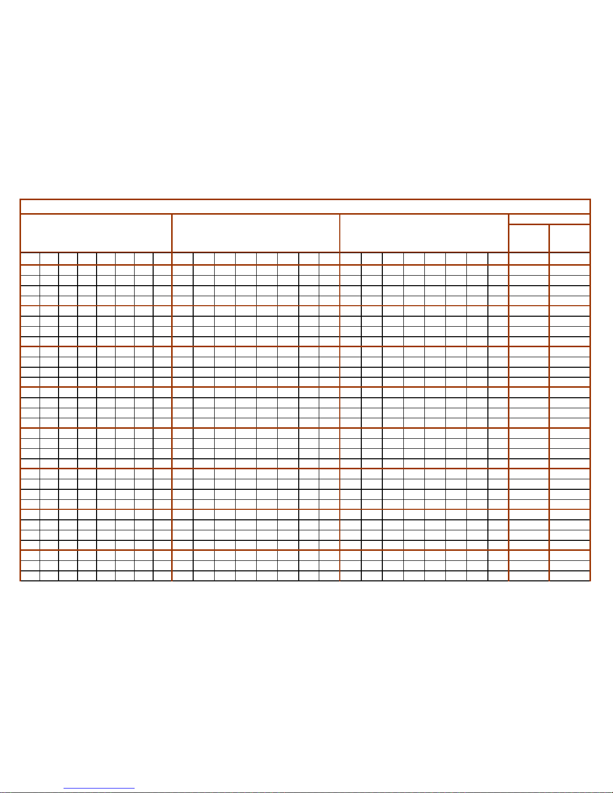
TOTAL
COOLING
CAPACITY
TOTAL
HEATING
CAPACITY
ADMISSIBLE COMBINATION EXAMPLES OF MULTIFLEX INVERTER
REAL COOLING CAPACITY
(OF EACH UNIT IN COMBINATION)
Kw
kW
Type of INDOOR UNITS CIRCUIT (×100W)
REAL HEATING CAPACITY
(OF EACH UNIT IN COMBINATION)
kW
18 18 18 50 40 1.75 1.75 1.75 4.86 3.89 2.00 2.00 2.00 5.56 4.44 14.00 16.00
18 18 18 50 32 1.85 1.85 1.85 5.15 3.29 2.12 2.12 2.12 5.88 3.76 14.00 16.00
18 18 18 50 25 1.95 1.95 1.95 5.43 2.71 2.23 2.23 2.23 6.20 3.10 14.00 16.00
18 18 18 50 18 2.07 2.07 2.07 5.74 2.07 2.36 2.36 2.36 6.56 2.36 14.00 16.00
18 18 18 40 71 1.53 1.53 1.53 3.39 6.02 1.75 1.75 1.75 3.88 6.88 14.00 16.00
18 18 18 40 60 1.64 1.64 1.64 3.64 5.45 1.87 1.87 1.87 4.16 6.23 14.00 16.00
18 18 18 40 56 1.68 1.68 1.68 3.73 5.23 1.92 1.92 1.92 4.27 5.97 14.00 16.00
18 18 18 40 18 2.25 2.25 2.25 5.00 2.25 2.57 2.57 2.57 5.71 2.57 14.00 16.00
18 18 18 40 2.34 2.34 2.34 5.20 3.06 3.06 3.06 6.81 12.22 16.00
18 18 18 71 18 1.76 1.76 1.76 6.95 1.76 2.01 2.01 2.01 7.94 2.01 14.00 16.00
18 18 18 71 2.02 2.02 2.02 7.95 2.30 2.30 2.30 9.09 14.00 16.00
18 18 18 60 60 1.45 1.45 1.45 4.83 4.83 1.66 1.66 1.66 5.52 5.52 14.00 16.00
18 18 18 60 56 1.48 1.48 1.48 4.94 4.61 1.69 1.69 1.69 5.65 5.27 14.00 16.00
18 18 18 60 40 1.64 1.64 1.64 5.45 3.64 1.87 1.87 1.87 6.23 4.16 14.00 16.00
18 18 18 60 18 1.91 1.91 1.91 6.36 1.91 2.18 2.18 2.18 7.27 2.18 14.00 16.00
18 18 18 60 2.21 2.21 2.21 7.37 2.53 2.53 2.53 8.42 14.00 16.00
18 18 18 56 71 1.39 1.39 1.39 4.33 5.49 1.59 1.59 1.59 4.95 6.28 14.00 16.00
18 18 18 56 25 1.87 1.87 1.87 5.81 2.59 2.13 2.13 2.13 6.64 2.96 14.00 16.00
18 18 18 56 18 1.97 1.97 1.97 6.13 1.97 2.25 2.25 2.25 7.00 2.25 14.00 16.00
18 18 18 56 2.29 2.29 2.29 7.13 2.62 2.62 2.62 8.15 14.00 16.00
18 18 71 60 1.51 1.51 5.95 5.03 1.72 1.72 6.80 5.75 14.00 16.00
18 18 71 56 1.55 1.55 6.10 4.81 1.77 1.77 6.97 5.50 14.00 16.00
18 18 71 50 25 1.38 1.38 5.46 3.85 1.92 1.58 1.58 6.24 4.40 2.20 14.00 16.00
18 18 71 50 1.61 1.61 6.33 4.46 1.83 1.83 7.24 5.10 14.00 16.00
18 18 71 40 32 1.41 1.41 5.55 3.13 2.50 1.61 1.61 6.35 3.58 2.86 14.00 16.00
18 18 71 40 25 1.47 1.47 5.78 3.26 2.03 1.67 1.67 6.60 3.72 2.33 14.00 16.00
18 18 71 40 1.71 1.71 6.76 3.81 1.96 1.96 7.73 4.35 14.00 16.00
18 18 71 32 40 1.41 1.41 5.55 2.50 3.13 1.61 1.61 6.35 2.86 3.58 14.00 16.00
TOTAL
COOLING
CAPACITY
TOTAL
HEATING
CAPACITY
ADMISSIBLE COMBINATION EXAMPLES OF MULTIFLEX INVERTER
REAL COOLING CAPACITY
(OF EACH UNIT IN COMBINATION)
Kw
kW
Type of INDOOR UNITS CIRCUIT (×100W)
REAL HEATING CAPACITY
(OF EACH UNIT IN COMBINATION)
kW
18 18 71 32 32 1.47 1.47 5.81 2.62 2.62 1.68 1.68 6.64 2.99 2.99 14.00 16.00
18 18 71 32 25 1.54 1.54 6.06 2.73 2.13 1.76 1.76 6.93 3.12 2.44 14.00 16.00
18 18 71 32 1.81 1.81 7.15 3.22 2.07 2.07 8.17 3.68 14.00 16.00
18 18 71 25 25 1.61 1.61 6.33 2.23 2.23 1.83 1.83 7.24 2.55 2.55 14.00 16.00
18 18 71 25 1.91 1.91 7.53 2.65 2.18 2.18 8.61 3.03 14.00 16.00
18 18 71 2.34 2.34 9.23 2.69 2.69 10.40 13.91 15.78
18 18 60 60 25 1.39 1.39 4.64 4.64 1.93 1.59 1.59 5.30 5.30 2.21 14.00 16.00
18 18 60 60 1.62 1.62 5.38 5.38 1.85 1.85 6.15 6.15 14.00 16.00
18 18 60 56 25 1.42 1.42 4.75 4.43 1.98 1.63 1.63 5.42 5.06 2.26 14.00 16.00
18 18 60 56 1.66 1.66 5.53 5.16 1.89 1.89 6.32 5.89 14.00 16.00
18 18 60 50 32 1.42 1.42 4.72 3.93 2.52 1.62 1.62 5.39 4.49 2.88 14.00 16.00
18 18 60 50 25 1.47 1.47 4.91 4.09 2.05 1.68 1.68 5.61 4.68 2.34 14.00 16.00
18 18 60 50 1.73 1.73 5.75 4.79 1.97 1.97 6.58 5.48 14.00 16.00
18 18 60 40 32 1.50 1.50 5.00 3.33 2.67 1.71 1.71 5.71 3.81 3.05 14.00 16.00
18 18 60 40 25 1.57 1.57 5.22 3.48 2.17 1.79 1.79 5.96 3.98 2.48 14.00 16.00
18 18 60 40 1.85 1.85 6.18 4.12 2.12 2.12 7.06 4.71 14.00 16.00
18 18 60 32 32 1.58 1.58 5.25 2.80 2.80 1.80 1.80 6.00 3.20 3.20 14.00 16.00
18 18 60 32 25 1.65 1.65 5.49 2.93 2.29 1.88 1.88 6.27 3.35 2.61 14.00 16.00
18 18 60 32 1.97 1.97 6.56 3.50 2.25 2.25 7.50 4.00 14.00 16.00
18 18 60 25 25 1.73 1.73 5.75 2.40 2.40 1.97 1.97 6.58 2.74 2.74 14.00 16.00
18 18 60 25 2.08 2.08 6.94 2.89 2.38 2.38 7.93 3.31 14.00 16.00
18 18 60 2.34 2.34 7.80 3.00 3.00 9.10 12.48 15.10
18 18 56 56 1.70 1.70 5.30 5.30 1.95 1.95 6.05 6.05 14.00 16.00
18 18 56 50 1.77 1.77 5.52 4.93 2.03 2.03 6.31 5.63 14.00 16.00
18 18 56 40 1.91 1.91 5.94 4.24 2.18 2.18 6.79 4.85 14.00 16.00
18 18 56 32 2.03 2.03 6.32 3.61 2.32 2.32 7.23 4.13 14.00 16.00
18 18 56 25 2.15 2.15 6.70 2.99 2.46 2.46 7.66 3.42 14.00 16.00
18 18 56 2.34 2.34 7.28 3.12 3.12 8.45 11.96 14.69
TOTAL
COOLING
CAPACITY
TOTAL
HEATING
CAPACITY
ADMISSIBLE COMBINATION EXAMPLES OF MULTIFLEX INVERTER
REAL COOLING CAPACITY
(OF EACH UNIT IN COMBINATION)
Kw
kW
Type of INDOOR UNITS CIRCUIT (×100W)
REAL HEATING CAPACITY
(OF EACH UNIT IN COMBINATION)
kW
18 18 50 50 1.85 1.85 5.15 5.15 2.12 2.12 5.88 5.88 14.00 16.00
18 18 50 40 2.00 2.00 5.56 4.44 2.29 2.29 6.35 5.08 14.00 16.00
18 18 50 32 2.14 2.14 5.93 3.80 2.44 2.44 6.78 4.34 14.00 16.00
18 18 50 25 2.27 2.27 6.31 3.15 2.59 2.59 7.21 3.60 14.00 16.00
18 18 50 2.34 2.34 6.50 3.12 3.12 7.80 11.18 14.04
18 18 40 40 2.17 2.17 4.83 4.83 2.48 2.48 5.52 5.52 14.00 16.00
18 18 40 32 2.33 2.33 5.19 4.15 2.67 2.67 5.93 4.74 14.00 16.00
18 18 40 25 2.34 2.34 5.20 3.25 2.85 2.85 6.34 3.96 13.13 16.00
18 18 40 2.34 2.34 5.20 3.12 3.12 6.50 9.88 12.74
18 18 32 32 2.34 2.34 4.16 4.16 2.88 2.88 5.12 5.12 13.00 16.00
18 18 32 25 2.34 2.34 4.16 3.25 3.10 3.10 5.51 4.30 12.09 16.00
18 18 32 2.34 2.34 4.16 3.12 3.12 5.20 8.84 11.44
18 18 25 25 2.34 2.34 3.25 3.25 3.12 3.12 3.90 3.90 11.18 14.04
18 18 18 18 71 32 1.44 1.44 1.44 1.44 5.68 2.56 1.65 1.65 1.65 1.65 6.49 2.93 14.00 16.00
18 18 18 18 71 25 1.50 1.50 1.50 1.50 5.92 2.08 1.71 1.71 1.71 1.71 6.76 2.38 14.00 16.00
18 18 18 18 71 1.76 1.76 1.76 1.76 6.95 2.01 2.01 2.01 2.01 7.94 14.00 16.00
18 18 18 18 60 50 1.38 1.38 1.38 1.38 4.62 3.85 1.58 1.58 1.58 1.58 5.27 4.40 14.00 16.00
18 18 18 18 60 40 1.47 1.47 1.47 1.47 4.88 3.26 1.67 1.67 1.67 1.67 5.58 3.72 14.00 16.00
18 18 18 18 60 25 1.61 1.61 1.61 1.61 5.35 2.23 1.83 1.83 1.83 1.83 6.11 2.55 14.00 16.00
18 18 18 18 60 1.91 1.91 1.91 1.91 6.36 2.18 2.18 2.18 2.18 7.27 14.00 16.00
18 18 18 18 56 50 1.42 1.42 1.42 1.42 4.40 3.93 1.62 1.62 1.62 1.62 5.03 4.49 14.00 16.00
18 18 18 18 56 40 1.50 1.50 1.50 1.50 4.67 3.33 1.71 1.71 1.71 1.71 5.33 3.81 14.00 16.00
18 18 18 18 56 25 1.65 1.65 1.65 1.65 5.12 2.29 1.88 1.88 1.88 1.88 5.86 2.61 14.00 16.00
18 18 18 18 50 50 1.47 1.47 1.47 1.47 4.07 4.07 1.67 1.67 1.67 1.67 4.65 4.65 14.00 16.00
18 18 18 18 50 2.07 2.07 2.07 2.07 5.74 2.36 2.36 2.36 2.36 6.56 14.00 16.00
18 18 18 18 40 40 1.66 1.66 1.66 1.66 3.68 3.68 1.89 1.89 1.89 1.89 4.21 4.21 14.00 16.00
18 18 18 18 32 2.42 2.42 2.42 2.42 4.31 2.77 2.77 2.77 2.77 4.92 14.00 16.00
18 18 18 18 32 32 1.85 1.85 1.85 1.85 3.29 3.29 2.12 2.12 2.12 2.12 3.76 3.76 14.00 16.00
TOTAL
COOLING
CAPACITY
TOTAL
HEATING
CAPACITY
ADMISSIBLE COMBINATION EXAMPLES OF MULTIFLEX INVERTER
REAL COOLING CAPACITY
(OF EACH UNIT IN COMBINATION)
Kw
kW
Type of INDOOR UNITS CIRCUIT (×100W)
REAL HEATING CAPACITY
(OF EACH UNIT IN COMBINATION)
kW
18 18 18 18 25 25 2.07 2.07 2.07 2.07 2.87 2.87 2.36 2.36 2.36 2.36 3.28 3.28 14.00 16.00
18 18 18 18 18 2.34 2.34 2.34 2.34 2.34 3.12 3.12 3.12 3.12 3.12 11.70 15.60
18 18 18 32 2.34 2.34 2.34 4.16 3.12 3.12 3.12 5.20 11.18 14.56
18 18 18 25 2.34 2.34 2.34 3.25 3.12 3.12 3.12 3.90 10.27 13.26
18 18 18 18 2.34 2.34 2.34 2.34 3.12 3.12 3.12 3.12 9.36 12.48
25 25 25 25 25 25 25 2.00 2.00 2.00 2.00 2.00 2.00 2.00 2.29 2.29 2.29 2.29 2.29 2.29 2.29 14.00 16.00
25 25 25 25 25 25 18 2.08 2.08 2.08 2.08 2.08 2.08 1.50 2.38 2.38 2.38 2.38 2.38 2.38 1.71 14.00 16.00
25 25 25 25 25 40 18 1.91 1.91 1.91 1.91 1.91 3.06 1.38 2.19 2.19 2.19 2.19 2.19 3.50 1.57 14.00 16.00
25 25 25 25 25 40 2.12 2.12 2.12 2.12 2.12 3.39 2.42 2.42 2.42 2.42 2.42 3.88 14.00 16.00
25 25 25 25 25 32 2.23 2.23 2.23 2.23 2.23 2.85 2.55 2.55 2.55 2.55 2.55 3.26 14.00 16.00
25 25 25 25 25 32 18 2.00 2.00 2.00 2.00 2.00 2.56 1.44 2.29 2.29 2.29 2.29 2.29 2.93 1.65 14.00 16.00
25 25 25 25 25 25 2.33 2.33 2.33 2.33 2.33 2.33 2.67 2.67 2.67 2.67 2.67 2.67 14.00 16.00
25 25 25 25 25 18 18 2.17 2.17 2.17 2.17 2.17 1.57 1.57 2.48 2.48 2.48 2.48 2.48 1.79 1.79 14.00 16.00
25 25 25 25 25 18 2.45 2.45 2.45 2.45 2.45 1.76 2.80 2.80 2.80 2.80 2.80 2.01 14.00 16.00
25 25 25 25 40 40 1.94 1.94 1.94 1.94 3.11 3.11 2.22 2.22 2.22 2.22 3.56 3.56 14.00 16.00
25 25 25 25 40 32 2.03 2.03 2.03 2.03 3.26 2.60 2.33 2.33 2.33 2.33 3.72 2.98 14.00 16.00
25 25 25 25 40 18 18 1.99 1.99 1.99 1.99 3.18 1.43 1.43 2.27 2.27 2.27 2.27 3.64 1.64 1.64 14.00 16.00
25 25 25 25 40 18 2.22 2.22 2.22 2.22 3.54 1.59 2.53 2.53 2.53 2.53 4.05 1.82 14.00 16.00
25 25 25 25 40 2.50 2.50 2.50 2.50 4.00 2.86 2.86 2.86 2.86 4.57 14.00 16.00
25 25 25 25 32 50 1.92 1.92 1.92 1.92 2.46 3.85 2.20 2.20 2.20 2.20 2.81 4.40 14.00 16.00
25 25 25 25 32 32 2.13 2.13 2.13 2.13 2.73 2.73 2.44 2.44 2.44 2.44 3.12 3.12 14.00 16.00
25 25 25 25 32 18 2.33 2.33 2.33 2.33 2.99 1.68 2.67 2.67 2.67 2.67 3.41 1.92 14.00 16.00
25 25 25 25 32 2.65 2.65 2.65 2.65 3.39 3.03 3.03 3.03 3.03 3.88 14.00 16.00
25 25 25 25 25 56 1.93 1.93 1.93 1.93 1.93 4.33 2.21 2.21 2.21 2.21 2.21 4.95 14.00 16.00
25 25 25 25 25 50 2.00 2.00 2.00 2.00 2.00 4.00 2.29 2.29 2.29 2.29 2.29 4.57 14.00 16.00
25 25 25 25 18 2.97 2.97 2.97 2.97 2.14 3.39 3.39 3.39 3.39 2.44 14.00 16.00
25 25 25 71 32 1.97 1.97 1.97 5.58 2.52 2.25 2.25 2.25 6.38 2.88 14.00 16.00
25 25 25 71 25 2.05 2.05 2.05 5.81 2.05 2.34 2.34 2.34 6.64 2.34 14.00 16.00
25 25 25 71 18 18 1.92 1.92 1.92 5.46 1.38 1.38 2.20 2.20 2.20 6.24 1.58 1.58 14.00 16.00
25 25 25 71 18 2.13 2.13 2.13 6.06 1.54 2.44 2.44 2.44 6.93 1.76 14.00 16.00
25 25 25 71 2.40 2.40 2.40 6.81 2.74 2.74 2.74 7.78 14.00 16.00
25 25 25 60 40 2.00 2.00 2.00 4.80 3.20 2.29 2.29 2.29 5.49 3.66 14.00 16.00
 Loading...