

Haier AU482FIERA, AU282FHERA, AU48NFIERAG, AU60NFIERA, AU60NFIERAG Installation & Maintenance Instructions Manual
...
SYJS-11-2015REV.D Edition: 11-2015
R410A HEAT PUMP
MRVIII-S (G)
Design, Installation &
Maintenance instruction
AU282FHERA
AU482FIERA (G)
AU48NFIERA (G)
AU60NFIERA (G)

CONTENTS
1. General Information .................................................................................................................. 1
2. Specication ............................................................................................................................. 2
3. Indoor Model List ...................................................................................................................... 6
4. Refrigerant Circuit..................................................................................................................... 7
5. Dimension............................................................................................................................... 10
6. Wiring Diagram ....................................................................................................................... 12
7. Performance Curves............................................................................................................... 15
8. Outdoor Installation ................................................................................................................ 18
9. Electric Installation.................................................................................................................. 29
10. Trial Operation and The Performance .................................................................................. 34
11. Failure Code ......................................................................................................................... 43
12. Troubleshooting .................................................................................................................... 45
APPENDIX............................................................................................................................58

1
1. General Information
MRVllI-S adopts refrigerant R410a, which is the new generation of H-MRV. It is with DC inverter technology, high
efciency and energy saving, intelligent control, etc. All indoor units are with EEV to adjust the refrigerant ow,
collect the data by the precise temp. sensor. lndoors adopt the indoors of MRVllI-C below 48000BTU/h, add the
central control, room card function on the basis of original H-MRV. The system can realize max. 1 to 9.
Features:
1. High efciency and energy saving
1.1 Precise control, optimum operation
a. Simulate pressure control, to realize every indoor unit energy-saving and optimum operation.
b. Adopt inverter technology, adjust outdoor total load according to the actual request.
1.2 Indoor individual control, economic running
1.3 Advanced technology, high efciency, and energy saving
1.4 High efcient rotary compressor
a. Precise control EEV
b. Excellent piping system design
c. Long distance of refrigerant piping
1.5 Inverter operation, temperature sensor technology, reduce power consumption
2. Beautiful and comfortable
a. Compact outdoor appearance design
b. Perfect cooling and heating, more comfortable
c. Super slim design, t for the decor
3. Healthy and environment friendly
a. Adopt environment friendly refrigerant R410a, protect ozone layer against the earth being warmed up
b. Intelligent healthy module for removing formaldehyde, easily resolve the decoration pollution
c. Strong ultraviolet radiation to kill the bacteria, make indoor air more healthy
4. More convenient
a. Flexible control indoors
One outdoor can control multiple indoors at the same time
b. Multiple indoor control types
Infrared control, wired control, infrared control + wired control, central control
c. Free combination
Due to the different space, select indoor type freely
d. Multiple air sending, air return types
5. Easy installation
Super long piping system, free installation
2
2. Specication
Model AU282FHERA AU482FIERA (G)
Power supply Ph/V/Hz 1/220~230/50 1/220~230/50/60
Cooling
Rated capacity kW 8 15
Rated capacity kBtu/h 27.3 51.2
Rated power input kW 2.2 4.2
Max. power input kW 4.1 6.2
EER 3.64 3.57
Rated current A 10.5 21.2
Max. current A 20.7 31.3
Heating
Rated capacity kW 9.5 17
Rated capacity kBtu/h 32.4 58
Rated power input kW 2.15 4
Max. power input kW 3.9 5.8
COP 4.42 4.25
Rated current A 10.3/19.8 20.2
Max. current A 19.8 29.3
Compressor
Brand MITSUBISHI ELECTRIC MITSUBISHI ELECTRIC
Model TNB220FLHMC LNB42F
Type Rotary Rotary
Compressor quantity 1 INV 1 INV
Capacity W 7130 13980W
Power input W 2200 4240W
Rated current (RLA) A 9.7 16.1
Speed rps 60 60
Crankcase heater W 27 28
Refrigerant oil brand IDEMITSUKOSAN CO.,LTD IDEMITSUKOSAN CO.,LTD
Refrigerant oil type FV50S FV50S
Refrigerant oil charge ml 870 1400
Outdoor fan motor
Brand BROAD OCEAN PANASONIC
Model Y6S443C81 EHDS80BAS
Voltage 208-230 208-230
IP class IP44 IP23
Type AC DC
Insulation class F E
Safe class I I
Power input W 260 124
Output W 110 100*2
Rated current A 1.2 0.4
Capacitor μF 5 /
Speed rpm 1000 960
Outdoor fan
Brand HONG MING SHUNWEI
Model / /
Material Plastic Plastic
Type Axial Axial
Diameter mm 450 450
Height mm 148 148

3
Model AU282FHERA AU482FIERA (G)
Outdoor coil
Number of rows 2 2
Tube pitch (a)×row pitch (b) mm 19.05×22 19.05×22
Fin spacing mm 1.70 1.5
Fin type (code)
HYDROPHILIC
ALUMINIUM
HYDROPHILIC
ALUMINIUM
Fin coating type Optional Clear lacquer Clear lacquer
Salt spray test duration Hour 168 168
Tube outside dia. and type
INNERGROOVE TUBE INNERGROOVE TUBE
mm Ф8 Ф8
Coil length×height mm 955×792 970×1200
Number of circuits 4 6
Cabinet coating
Coating type Powder coating Powder coating
Salt spray test duration Hour 72 72
Sheet metal material Hot zinc plate Hot zinc plate
Sheet metal thickness mm 0.8 0.8
Control panel enclosure IP class Standard IP24 IP24
Outdoor air ow m
3
/h 3500 6500
Outdoor sound level (sound pressure level ) dB (A) 55 59
Outdoor sound level (sound power level ) dB (A) 66 70
Outdoor unit
Dimension (W*H*D) mm 960×380×830 960×380×1250
Packing (W*H*D) mm 1095×410×985 1095×410×1400
Net weight kg 74 105
Gross weight kg 89 113
Refrigerant
Type R410A R410A
Charged volume kg 2.6 3.6
Throttle type EXV EXV
Design pressure MPa 4.15 4.15
Refrigerant piping
Liquid pipe mm 9.52 9.52
Gas pipe mm 15.88 19.05
Total pipe length m 50 100
Max. pipe length
(Equivalent/ Actual)
m 35 70
Max. Diff. indoor/outdoor unit m
30 (Outdoor higher than indoor)
20 (Indoor higher than outdoor)
Max. Diff. indoor/indoor unit m 10 10
Connectable indoor unit ratio % 50%~130% 50%~130%
Maximum indoor units Piece 4 8
Connection wiring
Power wiring mm
2
6 10
Signal wiring mm
2
Shield wire: (0.75-2)*2 Shield wire: (0.75-2)*2
Operation range °C
Cooling: 10~43
Heating: -15~21
Cooling: -15~43
Heating: -15~21
Nominal condition:
Indoor temperature (cooling): 27 DB(°C)/19 WB(°C), indoor temperature (heating): 20 DB(°C)/14.5 WB(°C).
Outdoor temperature (cooling): 35 DB(°C)/24 WB(°C), outdoor temperature (heating): 7 DB(°C)/6 WB(°C).
The data is measured with 7.5m equivalent pipe and 0m height difference.
The noise level will be measured in the third octave band limited values in the semi-anechoic chamber, using a real
time analyser calibrated sound intensity meter. It is a sound pressure noise level.

4
Model AU48NFIERA (G) AU60NFIERA (G)
Power supply Ph/V/Hz 3/380~400/50/60 3/380~400/50/60
Cooling
Rated capacity kW 15 18
Rated capacity kBtu/h 51.2 61.4
Rated power input kW 4.2 5.5
Max. power input kW 6.2 7.3
EER 3.57 3.27
Rated current A 6.7 9.8
Max. current A 10 13
Heating
Rated capacity kW 17 20
Rated capacity kBtu/h 58 68.2
Rated power input kW 4 5.25
Max. power input kW 5.8 6.7
COP 4.25 3.81
Rated current A 6.4 9.4
Max. current A 9.6 12
Compressor
Brand MITSUBISHI ELECTRIC MITSUBISHI ELECTRIC
Model LNB42F LNB42F
Type Rotary Rotary
Compressor quantity 1 INV 1 INV
Capacity W 13980W 13980W
Power input W 4270W 4270W
Rated current (RLA) A 12 12
Speed rps 60 60
Crankcase heater W 28 28
Refrigerant oil brand IDEMITSUKOSAN CO.,LTD IDEMITSUKOSAN CO.,LTD
Refrigerant oil type FV50S FV50S
Refrigerant oil charge ml 1400 1400
Outdoor fan motor
Brand PANASONIC PANASONIC
Model EHDS80BAS EHDS80BAS
Voltage 208-230 208-230
IP class IP23 IP23
Type DC DC
Insulation class E E
Safe class I I
Power input W 124 124
Output W 100*2 100*2
Rated current A 0.4 0.4
Capacitor μF / /
Speed rpm 960 960
Outdoor fan
Brand SHUNWEI SHUNWEI
Model / /
Material Plastic Plastic
Type Axial Axial
Diameter mm 450 450
Height mm 148 148
5
Model AU48NFIERA (G) AU60NFIERA (G)
Outdoor coil
Number of rows 2 2
Tube pitch (a)×row pitch (b) mm 19.05×22 19.05×22
Fin spacing mm 1.5 1.5
Fin type (code)
HYDROPHILIC
ALUMINIUM
HYDROPHILIC
ALUMINIUM
Fin coating type Optional Clear lacquer Clear lacquer
Salt spray test duration Hour 168 168
Tube outside dia. and type
INNERGROOVE TUBE INNERGROOVE TUBE
mm Ф8 Ф8
Coil length×height mm 970×1200 970×1200
Number of circuits 6 6
Cabinet coating
Coating type Powder coating Powder coating
Salt spray test duration Hour 72 72
Sheet metal material Hot zinc plate Hot zinc plate
Sheet metal thickness mm 0.8 0.8
Control panel enclosure IP class Standard IP24 IP24
Outdoor air ow m
3
/h 6500 6500
Outdoor sound level (sound pressure level ) dB (A) 59 60
Outdoor sound level (sound power level ) dB (A) 70 71
Outdoor unit
Dimension (W*H*D) mm 960×380×1250 960×380×1250
Packing (W*H*D) mm 1095×410×1400 1095×410×1400
Net weight kg 105 105
Gross weight kg 11 3 113
Refrigerant
Type R410A R410A
Charged volume kg 4 4
Throttle type EXV EXV
Design pressure MPa 4.15 4.15
Refrigerant piping
Liquid pipe mm 9.52 9.52
Gas pipe mm 19.05 19.05
Total pipe length m 100 100
Max. pipe length
(Equivalent/ Actual)
m 70 70
Max. Diff. indoor/outdoor unit m
30 (Outdoor higher than indoor)
20 (Indoor higher than outdoor)
Max. Diff. indoor/indoor unit m 10 10
Connectable indoor unit ratio % 50%~130% 50%~130%
Maximum indoor units Piece 8 9
Connection wiring
Power wiring mm
2
4 4
Signal wiring mm
2
Shield wire: (0.75-2)*2 Shield wire: (0.75-2)*2
Operation range °C
Cooling: -15~43
Heating: -15~21
Cooling: -15~43
Heating: -15~21
Nominal condition:
Indoor temperature (cooling): 27 DB(°C)/19 WB(°C), indoor temperature (heating): 20 DB(°C)/14.5 WB(°C).
Outdoor temperature (cooling): 35 DB(°C)/24 WB(°C), outdoor temperature (heating): 7 DB(°C)/6 WB(°C).
The data is measured with 7.5m equivalent pipe and 0m height difference.
The noise level will be measured in the third octave band limited values in the semi-anechoic chamber, using a
real time analyser calibrated sound intensity meter. It is a sound pressure noise level.

6
3. Indoor Model List
4-WAY CASSETTE TYPE/PB-700lB
AB092MCERA
AB122MCERA
AB162MCERA
HIGH WALL EEV INSIDE
AS072MGERA AS162MGERA
AS092MGERA AS182MGERA
AS122MGERA AS242MGERA
4-WAY CASSETTE TYPE/PB-950JB
AB182MCERA
AB242MCERA
AB282MCERA
AB302MCERA
AB382MCERA
AB482MCERA
MED ESP DUCT TYPE (80/120Pa)
AD182MZERA
AD242MZERA
AD282MZERA
AD302MNERA
AD382MNERA
AD482MNERA
LOW ESP DUCT TYPE
AD072MLERA
AD092MLERA
AD122MLERA
AD162MLERA
AD182MLERA
AD242MLERA
MED ESP DUCT TYPE (50/96Pa)
AD182MMERA
AD242MMERA
AD282MMERA
AD302MMERA
AD382MMERA
AD482MMERA
HlGH ESP DUCT TYPE
AD182MHERA
AD242MHERA
AD282MHERA
AD302MHERA
AD382MHERA
AD482MHERA
AD722MHERA
AD962MHERA
CONVERTlBLE TYPE
AC092MCERA
AC122MCERA
AC162MCERA
AC182MCERA
AC242MCERA
AC282MFERA
AC302MFERA
AC382MFERA
AC482MFERA
SLIM LOW ESP DUCT
AD072MSERA
AD092MSERA
AD122MSERA
AD162MSERA
AD182MSERA
AD242MSERA
BUILIT-IN FLOOR STANDING
AE072MLERA
AE092MLERA
AE122MLERA
AE162MLERA
AE182MLERA
AE242MLERA
2-WAY CASSETTE/1055IB
AB072MBERA
AB092MBERA
AB122MBERA
AB162MBERA
AB182MBERA
CONSOLE TYPE
AF072MAERA
AF092MAERA
AF122MAERA
AF182MAERA
FRESH AIR DUCT TYPE
AD482MPERA
AD722MPERA
AD962MPERA
7
4. Refrigerant Circuit
Ta
Liquid pipe
Tc
Strainer P MV Strainer
Strainer
Te S
4-way valve
Gas pipe
Oil segregator
SV1
OP
Oil return capillary
Ts
Td
Compressor
LP
Gas-liquid
Segregator
Legend
Connected
Disconnected
2cT PMV
Outdoor unit
Ta
Indoor unit
Tc1
Strainer
Strainer
Strainer
AU282FHERA
SV2
8
Ta
One-way valve Liquid pipe
室外 HEX T e
Tc Strainer
Strainer PMV Strainer S
Accumulator
4-way valve Gas pipe
Strainer SV1
Strainer
Oil segregator Strainer
OP Oil return capillary
Td Ts
LP
Gas-liquid
Segregator
Legend
Connected PMV
Tc2
Disconnected Ta Tc1
Outdoor
Indoor
Compressor
T
AU482FIERA (G), AU48NFIERA (G), AU60NFIERA (G)
SV2
9
Part name Model Sign Function Date
Compressor
AU282
Capacity control, meet indoor load
request by adjusting the frequency
Motor resistance
(at 20°C): 0.88Ω
AU482
Motor resistance
(at 20°C): 0.29Ω
AU48/60N
Motor resistance
(at 20°C): 0.53Ω
Pressure switch ALL
HP High pressure protection 4.15Mpa, OFF
LP Low pressure protection 0.05Mpa, OFF
Electronic expansion
valve
ALL PMV In heating, refrigerant ow control
¢
2.4
Solenoid valve ALL
SV1
Keep balance of high/low pressure
when compressor starts up or stops
AC220V
SV2
Refrigerant jet protection when
discharging temp. is too high
4-way valve ALL 4WV
Change over between cooling and
heating
AC220V, electried in heat;
not electried in cooling or
defrosting
Temp. sensor ALL
Te
Check frost condition of outdoor
heat exchanger
R (25°C)=10K B
(25/50°C)=3700K
Ts
Detect the suction temp. of
compressor
Tc
Check the temp. of main pipe of
condenser gas pipe control PMV in
heating
Ta
Detect ambient temp. set primary
setting for fan speed target
pressure and PMV open angle
Td
Detect the discharging temp. of
compressor
R (80°C)=50K B
(25/80°C)=4450K
Heater
AU282
HEATER Used to heat oil in compressor
25W, 220V
AU482/48N/60N 28W, 220V
10
5. Dimension
AU282FHERA
AU482FIERA (G), AU48NFIERA (G), AU60NFIERA (G)
11
1. Single unit scenario
Over
Over
Over
OverOver
Over
Over
Over
Over
Over
Over
The top and two side surfaces must be exposed to open space, and obstacles on at least one side of the front
and back shall be lower than the outdoor unit.
※
2. Multiple units scenario:
Over
Over
Over
Over Over Over Over
Over Over
Obstacles shall be lower than the outdoor unit.
※
3. Front-and-back: Standard size
Over Over Over Over Over
.
The top and two side
surfaces must be exposed
to open space, and
obstacles on at least one
side of the front and back
shall be lower than the
outdoor unit
Back
Front
Front and prole
Obstacles
shall be
lower than
the outdoor
unit
Front and back
Front and back
Back and prole
When there are obstacles above
12
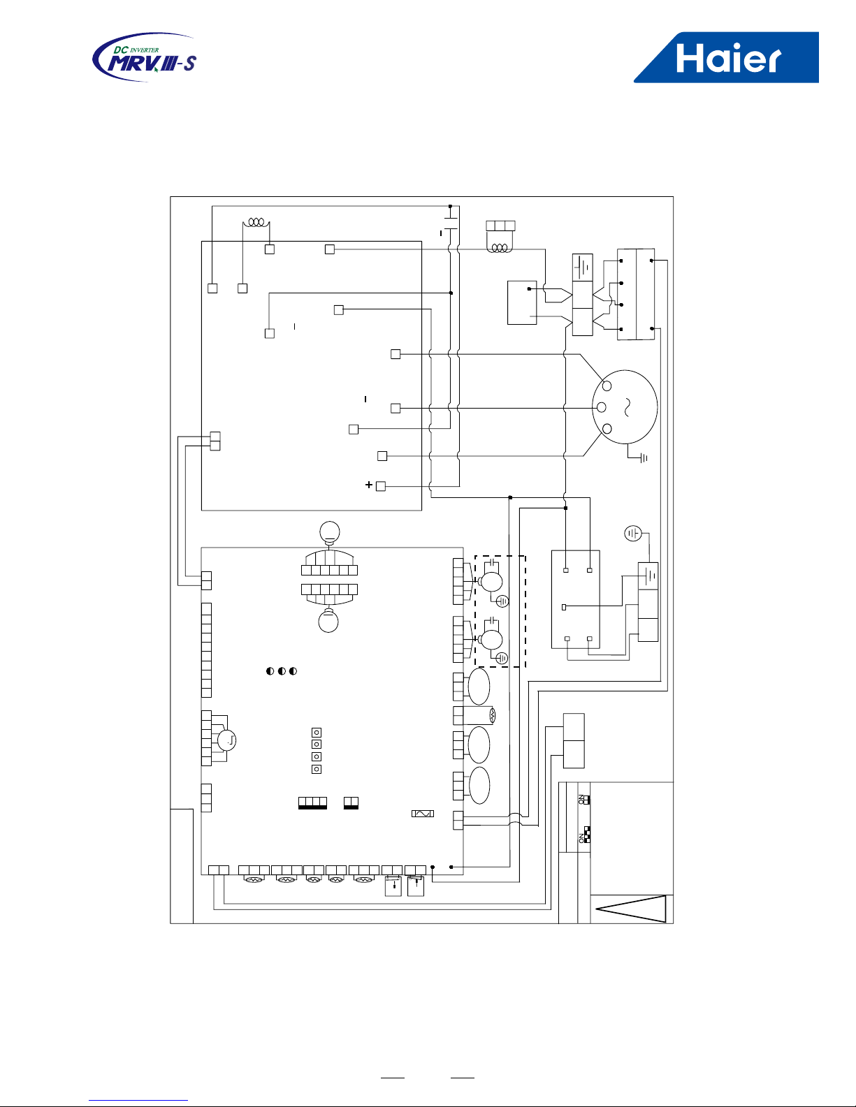
6. Wiring Diagram
Control board
I P M
NOISE FILTER
CN11
CN6
NO
COM
CN5
LN
CN1
CN2
CN3
CN4(PTC)
CON2
CON3
CN2
CN1
HP
LP
CN5
CN4
CN7
CN6
CN3
TCTETD
TS
TA
(OUT/IN_COM )CN21
P
Q
PMV
CN8
MODULE_COM
CN10
4-WAYS V2
HEATER
CN14
ACFAN1
FAN MOTOR
STARTUP CAPACITOR
CN9
CN2C N1
CN3
CN4
CN5(U)
CN6(V)
CN7(W)
P M V
U
W
V
COMP
HEATER
4-WAY VALVE
SPRAY VALVE
ISPM TEMPERATURE SENSOR
0150503461
Communication wire
with indoor unit
POWER SUPPLY
Y: yellow G: green
B: black BL: blue
W: white R: red
CN19
B
W
W
B
R
W
WB
B
Y/G
Y/G
WB
AU282FHERA
13
AU482FIERA (G)
P
SV2
P Q
SV1 4WV
HEATER
P
L
N
1
6
2 3 4
5
L
N
CN603 CN609
V
W
L
ACL
ACN
L
L
N
LINE
LOAD
L
N
+
U
Y
/
G
U
V
W
R W B
.
CURRENT
B W
B W
ACL
ACN
PTC
UP
M
DCFAN
SW01
CN20
CN8
CN24 CN11
EEV
M
LED_DISPLAY MODULE_COM
CN21
CN7
CN6
CN5
CN4
CN3
CN2
OUT/IN
TS
TE
TD
LP
CN1
CN19 CN18 CN17 CN25 CN16 CN15 CN14
(DOWN)
T6.3A/250VAC
ACFAN2 ACFAN1
(UP)
HP
TC
TA
SW02
M
DOWN
CN13
CN12
B
M
M
B
B
W
W
W
NOISE FILTER
SW01
SW02
482
TYPE
SETTING
COMMUNICATION WIRE
WITH INDOOR UINIT
Note:
Parts in dashed line are
optional. Arrow on current
transducer aims at side of
compressor
B:Black W:White R:Red
Y:Yellow G:Green
0150510341
1 2 3
1 2 3 4 5 6
1 2 3 4 5 6 7 8 9
10 A B
CN19
1 2
CN615
CN614
CN616
CN612
CN610
CN608
CN602
CN20
PTC
CN613
CN611
DC+
DC
DC
DC
SW4 SW3 SW2 SW1
ON
1 21 2 3 4
ON
DIP
6 5 4 3 2 1
6 5 4 3 2 1
Y
/
G
1 2
1 2 3 1 2 3
1 2
1 2 3
1 2 3 4 5 1 2 3 4 5
1 2
1 2
1 2 3 1 2 1 2 1 2 3
1 2 3 1 2
Reactor
LED3
LED2
LED1
Capacitance
123
!
Control Board
Inverter Module
When first powered up,the LED2
flicker times by 1Hz frequency ind-
icate model 482 flicker 4 times).
The LED2 flicker times by 2Hz freq-
uency indicate the searched indoor
numbers. When make sure correct,
SW01_4 dip is set on,or the machi-
ne can't run.
DC FAN SW01-1 dip switch is set ON
AC FAN SW01-1 dip switch is set OFF
14
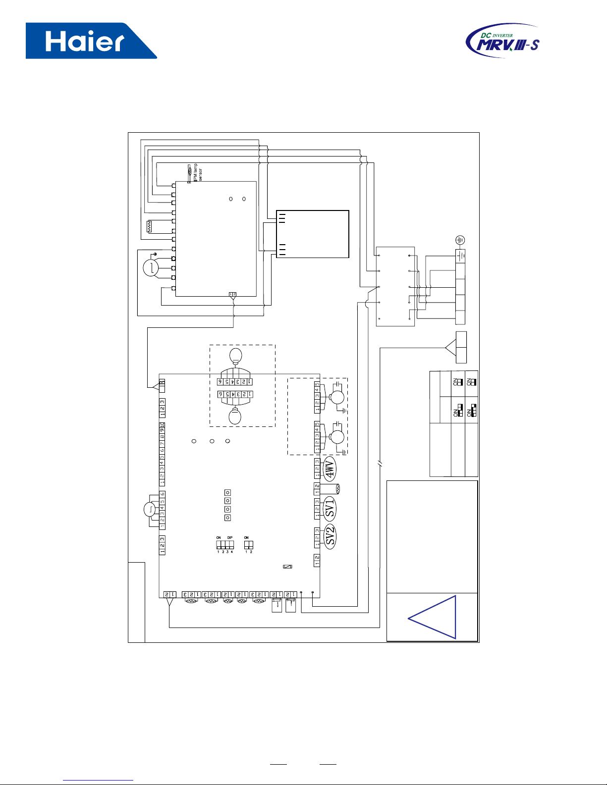
AU48NFIERA (G), AU60NFIERA (G)
SW02
T
S
R
DC+L2 L1 DC-T S R
CN604
LED601
LED602
IGBT
R
W B
BL
Y/G
E
N L3
L2
L1
NOISE FILTER
E
N
L3
L2
L1
P
Q
R
S T
N
W
B
G
R
W
W
W
SW01
SW02
!
U
R
V
W
W
B
COMP
P W V U N
CN607
+CD +CD
P
P
M
M
CN12
(DOWN)
(DOWN)
(UP)
(UP)
M
CN7
TA
CN6
TS
CN2
LP
CN1
HP
CN21
OUT/IN
CN20
CURRENT
EEV
CN24
LED_DISPLAY
ACL
ACN
CN19 CN18 CN17 CN25 CN16
PTC
CN15 CN14
CN13
DCFAN2
ACFAN1
M
SW01
SW4 SW3 SW2 SW1
DCFAN1
ACFAN2
A
T6.3A-250VAC
FUSE1
LED1 LED2 LED3
R
G
R
CN3
TD
CN4
TE
CN5
TC
CN10
CN11
MODULE_COM
HEATER
CN8
B
B
W
WW
AU48NFIERA(G)
Note:
Parts in dashed line are optional.
Arrow on current transducer aims at
side of compressor
TYPE
SETING
REACTOR
IPM temp
sensor
0150510342
The LED2 flicker times by 2Hz frequency indic-
ate the searched indoor numbers. When make
sure correct,SW01_4 dip is set on,or the machi-
ne can't run.
B:Black W:White R:Red Y:Yellow G:Green
DC FAN SW01-1 dip switch is set ON
AC FAN SW01-1 dip switch is set OFF
When first powered up, please make
sure SW01 dip switch is accord with
the right excel. The LED2 flicker times
by 1HZ frequency indicate model(48N
flicker 5 times, 60N flicker 6 times)
AU60NFIERA(G)
Control Board
15
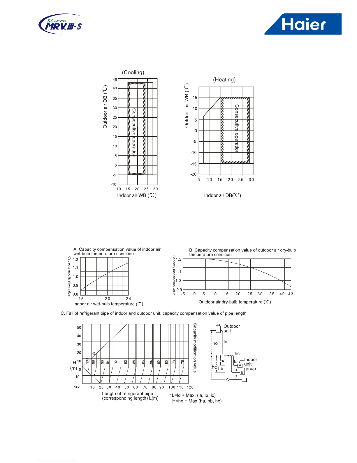
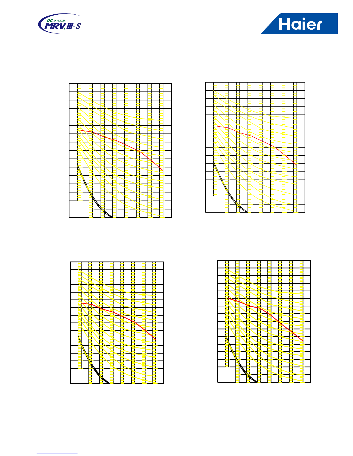
7. Performance Curves
7.1 Running range
Note
: AU282FHERA lowest cooling temperature is 10.
7.2 Calculation method
(1) Calculation method of refrigerating capacity---Refrigerating capacity to be known
=Refrigerating capacity×(A×B×C×D×E) W
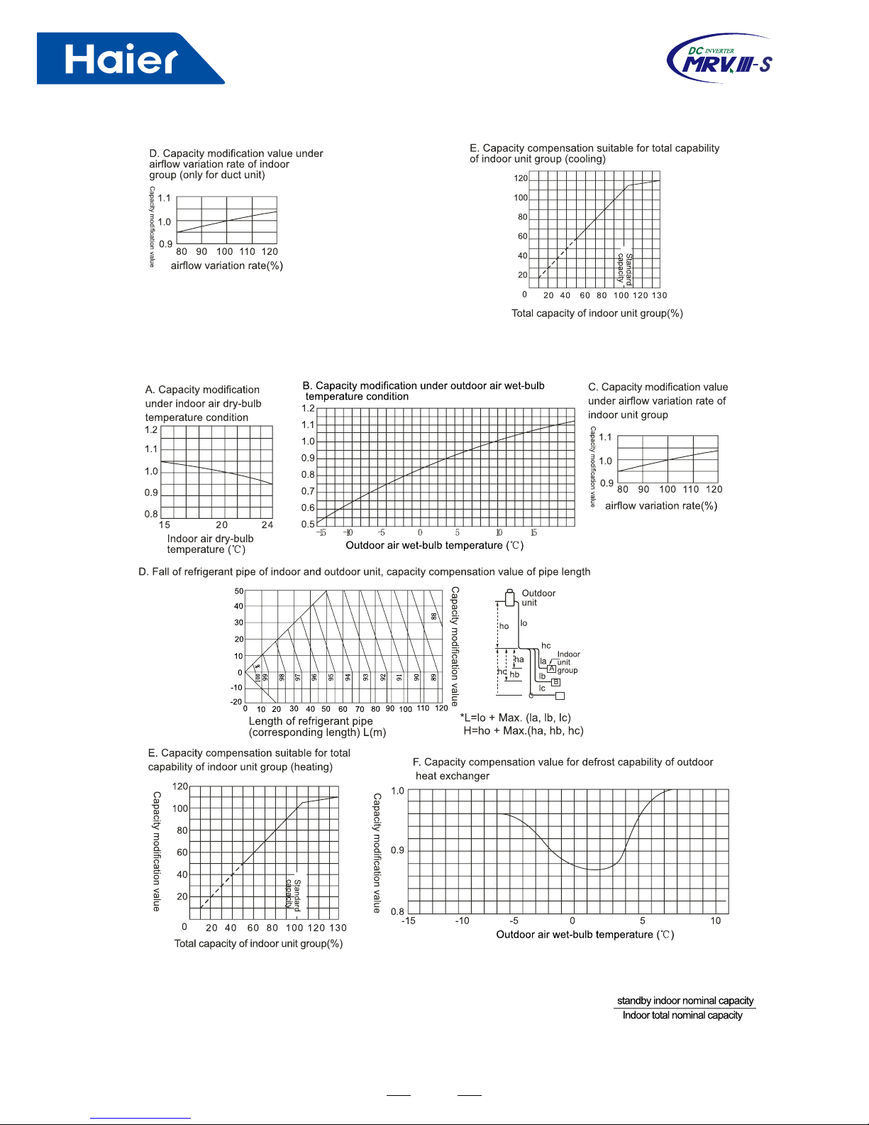
16
(2) Calculation method of heating capacity---Heating capacity to be known
= Heating capacity×(A×B×C×D×E×F) W
Outdoor modied capacity with a single indoor running = outdoor modied capacity *
(3) Calculation method of refrigerating capacity---Only one indoor unit running
(Outdoor modied capacity: heating or cooling capacity after modify item 1 and 2)
unit
17
20
30
40
50
60
80
70
AU282FHERA
1252 50 500 1000 2000 4000 800063
NC-20
NC-30
NC-40
NC-50
NC-60
NC-70
Octave band center frequency
Octave band sound pressure level
dB
Limit of audible
continuous
noise
20
30
40
50
60
80
70
AU482FIERA(G)
63 1252 50 500 1000 2000 4000 8000
NC-20
NC-30
NC-40
NC-50
NC-60
NC-70
Octave band center frequency (Hz)
Octave band sound pressure level
dB
Limit of audible
continuous
noise
20
30
40
50
60
80
70
00010 0020 0040 008365 210 520 05
NC-20
NC-30
NC-40
NC-50
NC-60
NC-70
20
30
40
50
60
80
70
00010 0020 0040 008365 210 520 05
NC-20
NC-30
NC-40
NC-50
NC-60
NC-70
Octave band center frequency
Octave band center frequency
Octave band sound pressure level dB
Octave band sound pressure level
dB
Limit of audible
continuous
noise
Limit of audible
continuous
noise
AU48NFIERA(G)
AU60NFIERA(G)
(Hz)
(Hz)
(Hz)
7.3 Noise level
18
8. Outdoor Installation
8.1 Installation cautions
SAFETY PRECAUTIONS
■ Please read these "Safety Precautions" rstly then accurately execute the installation work.
■ Though the precautionary points indicated herein are divided under two headings, "WARNING" and "CAUTION",
those points which are related to the strong possibility of an installation done in error resulting in death or
serious injury are listed in the "WARNING" section. However, there is also a possibility of serious consequences
in relationship to the points listed in the "CAUTION" section as well. In either case, important safety related
information is indicated, so by all means, properly observe all that is mentioned.
■ After completing the installation, along with conrming that no abnormalities were seen from the operation tests,
please explain operating methods as well as maintenance methods to the user (customer) of this equipment,
based on the owner's manual.
■ Moreover, ask the customer to keep this sheet together with the owner's manual.
WARNING
■ This system should be applied to places of ofce, restaurant, residence and the like. Application to inferior
environment such as engineering shop could cause equipment malfunction.
■ Please entrust installation to either the company which sold you the equipment or to a professional contractor.
Defects from improper installations can be the cause of water leakage, electric shocks and res.
■ Execute the installation accurately, based on following the installation manual. Again, improper installations can
result in water leakage, electric shocks and res.
■ When a large air-conditioning system is installed to a small room, it is necessary to have a prior planned
countermeasure for the rare case of a refrigerant leakage, to prevent the exceeding of threshold concentration. In
regards to preparing this countermeasure, consult with the company from which you purchased the equipment,
and make the installation accordingly. In the rare event that a refrigerant leakage and exceeding of threshold
concentration does occur, there is the danger of a resultant oxygen deciency accident.
■ For installation, conrm that the installation site can sufciently support heavy weight. When strength is
insufcient, injury can result from a falling of the unit.
■ Execute the prescribed installation construction to prepare for earthquakes and the strong winds of typhoons and
hurricanes, etc. Improper installations can result in accidents due to a violent falling over of the unit.
■ For electrical work, please see that a licensed electrician executes the work while following the safety standards
related to electrical equipment, and local regulations as well as the installation instructions, and that only
exclusive use circuits are used. Insufcient power source circuit capacity and defective installment execution can
be the cause of electric shocks and res.
■ Accurately connect wiring using the proper cable, and insure that the external force of the cable is not conducted
to the terminal connection part, through properly securing it. Improper connection or securing can result in heat
generation or re.
■ Take care that wiring does not rise upward, and accurately install the lid/service panel. Its improper installation
can also result in heat generation or re.
■ When setting up or moving the location of the air conditioner, do not mix air etc. or anything other than the
designated refrigerant (please see nameplate) within the refrigeration cycle.
■ Rupture and injury caused by abnormal high pressure can result from such mixing.
■ Always use accessory parts and authorized parts for installation construction. Using parts not authorized by this
company can result in water leakage, electric shock, re and refrigerant leakage.
19
CATUION
■ Execute proper grounding. Do not connect the ground wire to a gas pipe, water pipe, lightening rod or a
telephone ground wire.
■ Improper placement of ground wires can result in electric shock.
■ The installation of an earth leakage breaker is necessary depending on the established location of the unit.
■ Not installing an earth leakage breaker may result in electric shock.
■ Do not install the unit where there is a concern about leakage of combustible gas. The rare event of leaked gas
collecting around the unit could result in an outbreak of re.
■ For the drain pipe, follow the installation manual to insure that it allows proper drainage and thermally insulate it
to prevent condensation. Inadequate plumbing can result in water leakage and water damage to interior items.
8.2 Refrigerant piping
Outdoor
Indoor 1
Indoor 2
Indoor 3
Indoor 4
a. Pipe "a" diameter (between indoor and branch pipe) (depends on indoor pipe)
Indoor(×100W) 07~09 Gas pipe φ9.52 Liquid pipe φ6.35
12~18 φ12.7 φ6.35
24 φ15.88 φ9.52
b. Pipe "b" diameter (between branch pipe)
The branch pipe diameter depends on the total capacity of indoors connected with it. If indoor capacity is more than
outdoor capacity, it is conrmed by the outdoor capacity.
Total indoor capacity after the branch pipe (100W) Gas pipe Liquid pipe
<112 φ15.88 φ9.52
112<X<234 φ19.05 φ9.52
 Loading...