

Page 1
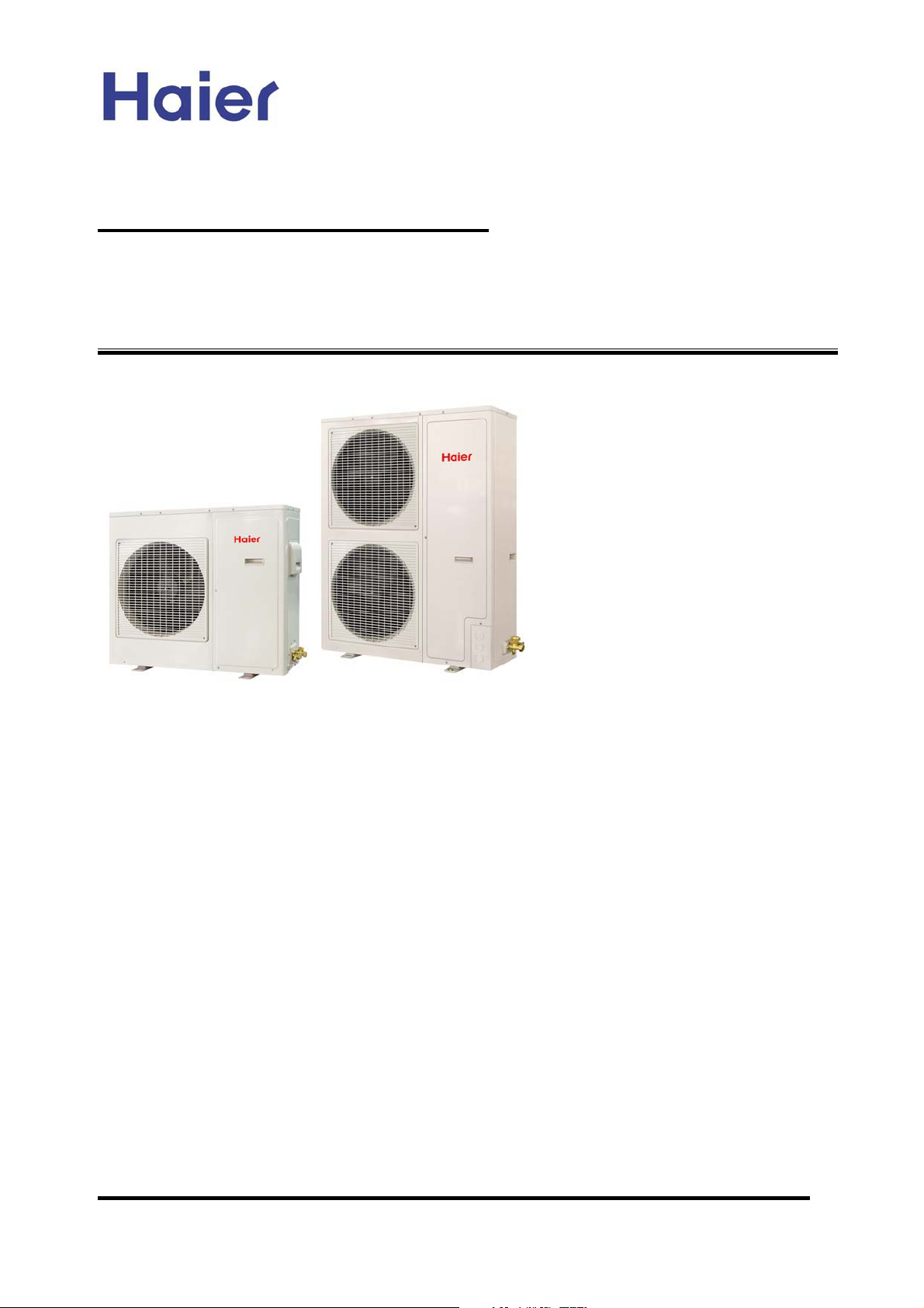
Commercial Air Conditioning
SERVICE MANUAL
Models
AU242FHBIA
AU482FIBIA
AU48NFIBJA
And its indoor units
zFeatures
zNew cassette unit, with 700*700 panel and new unit body
zNew PCB for cassette indoor unit and outdoor unit, much stabler
zMutiple indoor unit types: cassette type, ceiling concealed type, and wall
mounted type
zFree combination, total indoor capacity can be 50%~130% of outdoor capacity
zMultiple control types, infrared control+wired control
zIndividual operation for every indoor uint, energy saving
zNew refrigerant control device: MP2A, MP3A
zAuto restart function
zLong piping and high drop between indoor and outdoor
zRefrigerant: R407C
Manual code: SYJS-017-05REV.0 Edition: 2005-11-22
Page 2
Commercial Air Conditioner Model: AU242FHBIA,
AU482FIBIA, AU48NFIBJA
CONTENTS
Contents………………………………………………………...2
1. Description of products & features………………………..3
2. Specification…………………………………………………6
3. Safety precaution…………………………………………...14
4. Net dimension……………………………………………….16
5. Installation instructions………..……………………………21
6. Parts and functions………………………………………….53
7. Controller functions.............………………………………..21
8. Electrical control functions…………………………………71
9. Wiring diagrams…………………………………………….95
10. Failure code and troubleshooting………………………..99
11. Noise level……………………………………...................121
12. Performance curves......................................................124
-2-
Page 3
Commercial Air Conditioner Model: AU242FHBIA,
AU482FIBIA, AU48NFIBJA
1.DESCRIPTION OF PRODUCTS & FEATURES
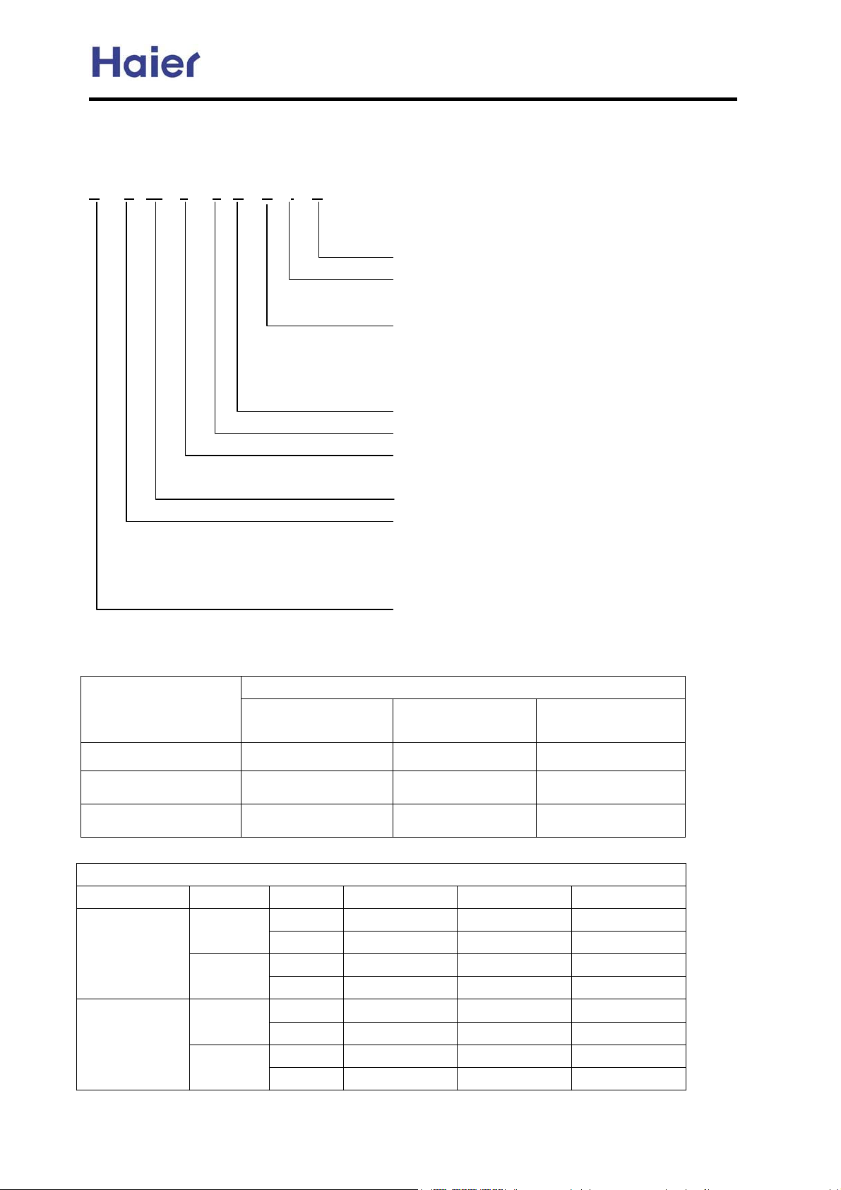
1.1. Products code explanation
A B 14 2 F C B I A
Climate type: T1 (see table 1)
Design number (I stands for design sequence, inverter
frequency type)
Product type: A stands for heat pump type, refrigerant is R22
B stands for heat pump type, refrigerant is R407C
M stands for cool only type, refrigerant is R22
N stands for cool only type, refrigerant is R407C
Appearance code
Product series: F stands for MRV
Applicable voltage: 2 stands for 220-230V/50Hz,
4 stands for 220V/60HzˈN stand for 380-400V/50Hz
Cooling / Heating capacity,14=14000BTU/h
Product type : “B” stands for cassette type, “C” stands for
convertible type, ”D” stands for duct, “S” stands for split
type, ”Q” stands for chiller system, "E" stands for ceiling
concealed type, “U” stands for outdoor unit
Air Conditioner
1.2 Brief Introduction for T1ǃT2ǃT3 working condition
Climate type
Type of Air
Conditioner
Cooling Only
Heat pump
Electricity Heating
T1 T2 T3
18 ć~43ć 10ć~35ć 21ć~52ć
-7ć~43ć -7ć~35ć -7ć~52ć
~43ć ~35ć ~52ć
1.3 Operating Range of Air Conditioners
Working temperature range
Rated Maximum Minimum
Cooling
Heating
Indoor
outdoor
Indoor
outdoor
DBć
WBć
DBć
WBć
DBć
WBć
DBć
WBć
27 32 18
19 23 14
35 43 -5
24 26 --
20 27 15
14.5 -- --
7 24 -15
6 18 --
-3-
Page 4
Commercial Air Conditioner Model: AU242FHBIA,
AU482FIBIA, AU48NFIBJA
1.4 Product features
New designed panel 700*700 with the 600*600 cassette unit
New designed swing louver with the non smooth surface, which can hold back the condensant water.
New designed filter lock, which will fix the filter more firmly than before.
Adopts the stepping motor, give the louver a larger swing angel.
New fan with bigger diameter fan blade, sending out larger air flow.
The cassette indoor unit adopts the panel whose dimension is identical to that of ceiling, after installation,
the unit will be accordant with the decoration decor.
Free combination, total indoor capacity can be 50%~130% of that of outdoor capacity
The outdoor unit can match with all types of indoor unit with the allowable capacity, such as the cassette
type, the ceiling concealed type, the wall mounted type, etc.
Optional control types: infrared remote controller and wired controller
The unit can be controlled by the smart infrared remote controller YR-H71, which can realize many
functions such as heating, cooling, fan, swing, fresh, health, filter up/down, electric heating, etc.
Furthermore, the remote controller can be compatible with many old controllers, more convenient for
utilizing.
If the unit is with wired controller YR-E06, which can realize remote control type by adding an infrared
controller YR-H71.
Auto-check function
The unit can display the malfunction codes on the control board by using advanced auto-check
technology, convenient for user find and dwell with the abnormal running.
Auto–restart function (optional)
All indoor units have auto-restart function. When the power supply cut off suddenly, the unit will
automatically recover the previous running mode once the power supply is on.
New refrigerant control device: MP2A, MP3A
The new refrigerant control device MP2A and MP3A replace the previous device MP2 and MP3. The new
device includes gas pipe and liquid pipe, more convenient for installation than before.
-4-
Page 5
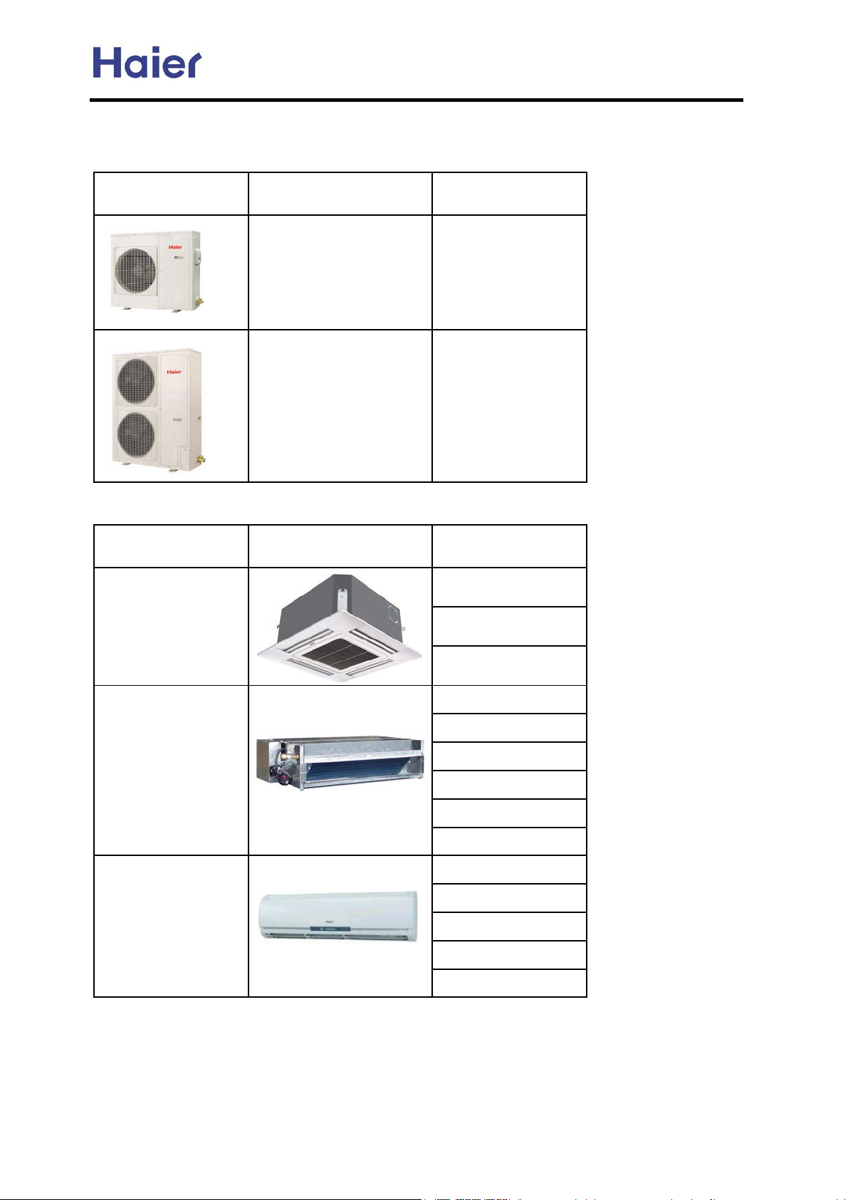
Commercial Air Conditioner Model: AU242FHBIA,
Total unit:
outdoor units
appearance model refrigerant
AU482FIBIA, AU48NFIBJA
indoor units
type appearance model
Four way cassette
AU242FHBIA
AU482FIBIA
AU48NFIBJA
R407C
R407C
AB092FCBIA
AB142FCBIA
AB182FCBIA
Ceiling concealed
Wall-mounted
(colorful screen)
AE072FCBKA
AE092FCBKA
AE122FCBKA
AE142FCBKA
AE182FCBKA
AE242FCBKA
AS072FCBHA
AS092FCBHA
AS122FCBHA
AS142FCBHA
AS182FCBHA
-5-
Page 6
Commercial Air Conditioner Model: AU242FHBIA,
AU482FIBIA, AU48NFIBJA
2. SPECIFICATION
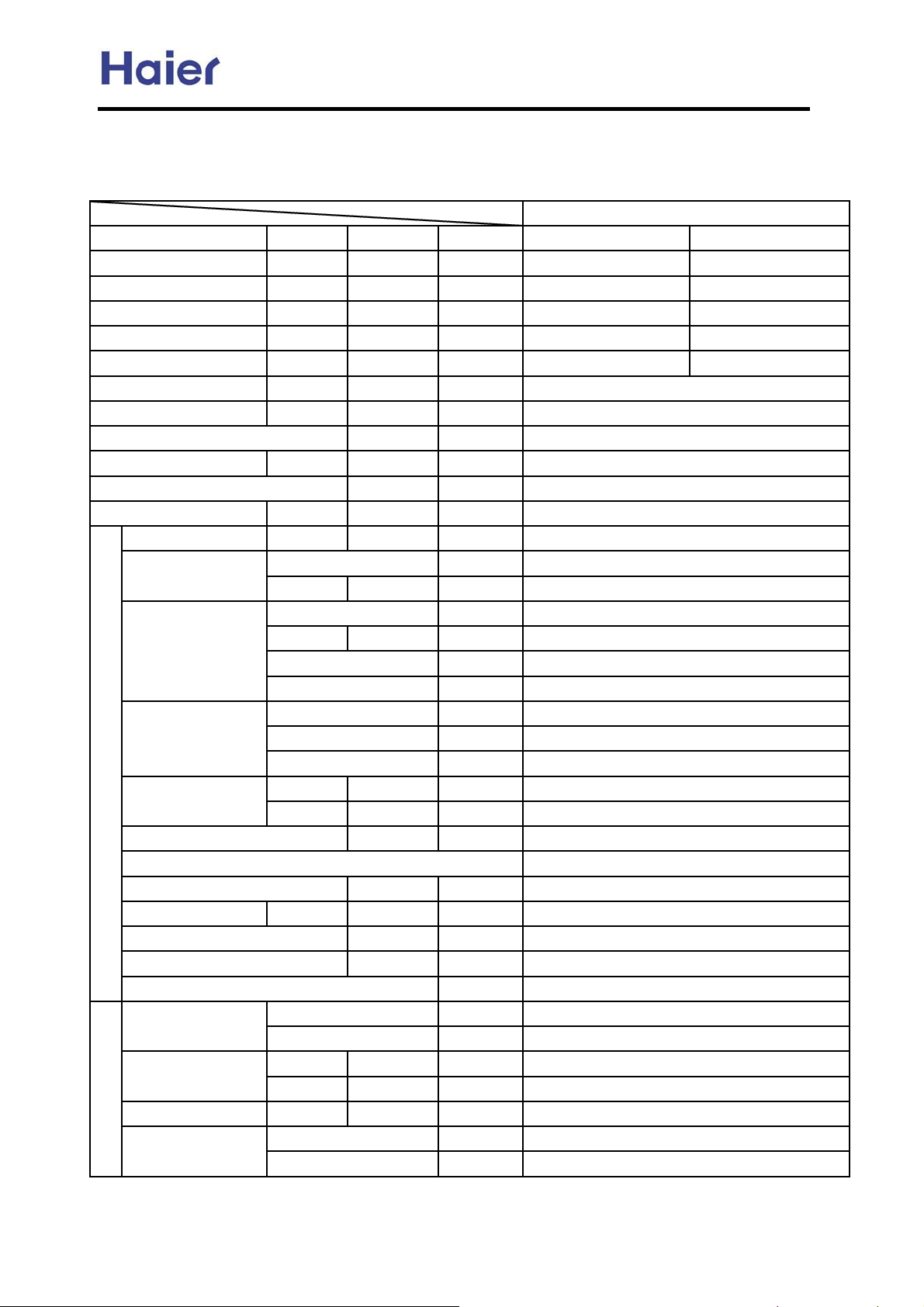
AU242FHBIA
Item Model AU242FHBIA
Function cooling heating
Capacity BTU/h
Capacity W
Total power input
Max. power input
EER or COP
W
W
W/W 2.2 2.55
Power cable
Power source
Running /Max.Running current
NˈVˈHz
A / A
Start Current A
Working frequency range Hz
Fuse A
Unit model (color)
Compressor
Model / Manufacture
Type
Type × Number
Fan
Speed r/min
Fan motor output power kW
Air-flow(H-M-L) m³/h
Type / Diameter mm
Heat exchanger
Dimension
Outdoor unit
Row*fin pintch
Temp. scope
External
Package
˄L×W×H˅
˄L×W×H˅
ć
mm×mm×mm
mm×mm×mm
Refrigerant control method mm/mm
Defrosting
Volume of Accumulator L
Noise level dB(A)
material of reduce noise
crankcase heater power W
Weight (Net / Shipping)
Refrigerant
Type / Charge g
kg / kg
Recharge quantity g/m
Pipe
Liquid mm
Gas mm
PIPING
Connecting Method
Between I.D &O.D
MAX.Drop
MAX.Piping length
m
m
24000 27000
7030 7910
3200 3100
3800 3800
2
6mm
1PH,220-230V~,50Hz
cooling: 18A/21A heating: 17/21A
--
30-105
3.15A 250V AC
AU242FHBIA (white)
C-7RB267H03AA/ SANYO SHENYANG
ROTARY
AXIAL*1
840±30/780±30/550±50
60*1
3240
inner grooved copper pipe ¶9.52
2*1.5mm
--
948X830X340
1050X979X440
EEV
AUTO
--
58
--
30
74/89
R407C/3200
ij9.52 liquid pipe: 65g/mhactual length
¶9.52
¶15.88
flared
outdoor upper: 30, outdoor lower: 20
50
-6-
Page 7
AU482FIBIA
Commercial Air Conditioner Model: AU242FHBIA,
AU482FIBIA, AU48NFIBJA
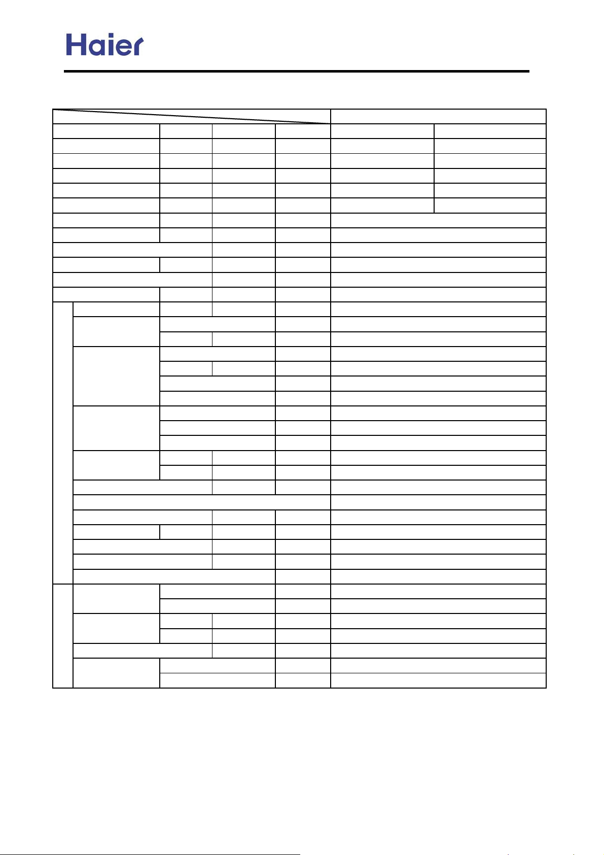
Item Model
AU482FIBIA
Function cooling heating
Capacity BTU/h
Capacity W
Total power input
Max. power input
EER or COP
W
W
W/W
Power cable
Power source
Running /Max.Running current
NˈVˈHz
A / A
Start Current A
Working frequency range Hz
Fuse A
Unit model (color)
Compressor
Model / Manufacture
Type
Type × Number
Fan
Speed r/min
Fan motor output power kW
Air-flow(H-M-L) m³/h
Type / Diameter mm
Heat exchanger
Dimension
Outdoor unit
Row*fin pintch
Temp. scope
External
Package
˄L×W×H˅
˄L×W×H˅
ć
mm×mm×mm
mm×mm×mm
Refrigerant control method mm/mm
Defrosting
Volume of Accumulator L
Noise level dB(A)
material of reduce noise
crankcase heater power W
Weight (Net / Shipping)
Refrigerant
Pipe
PIPING
Connecting Method
Between I.D &O.D
Type / Charge g
Recharge quantity g/m
Liquid mm
Gas mm
MAX.Drop
MAX.Piping length
kg / kg
m
m
48000 61000
14000 18000
6500 6000
7500 7500
2.15 3.00
2
16mm
1PH,220-230V~,50Hz
cooling: 34A/42A heating: 30/40A
--
30-105
3.15A 250V AC
AU482FIBIA (white)
EEV48FAL1/MITSUBISHI ELECTRIC
SCROLL
AXIAL*2
920±30r/min/840±40r/min/560±50r/min
65*2
7480
inner grooved copper pipe ¶9.52
2*1.5mm
43-60
1250X948X340
1375X1050X440
EEV
AUTO
--
58
--
40
120/135
R407C/4200
ij9.52 liquid pipe: 65g/mhactual length
¶9.52
¶19.05
flared
outdoor upper: 30, outdoor lower: 20
100
-7-
Page 8
AU48NFIBJA
Commercial Air Conditioner Model: AU242FHBIA,
AU482FIBIA, AU48NFIBJA
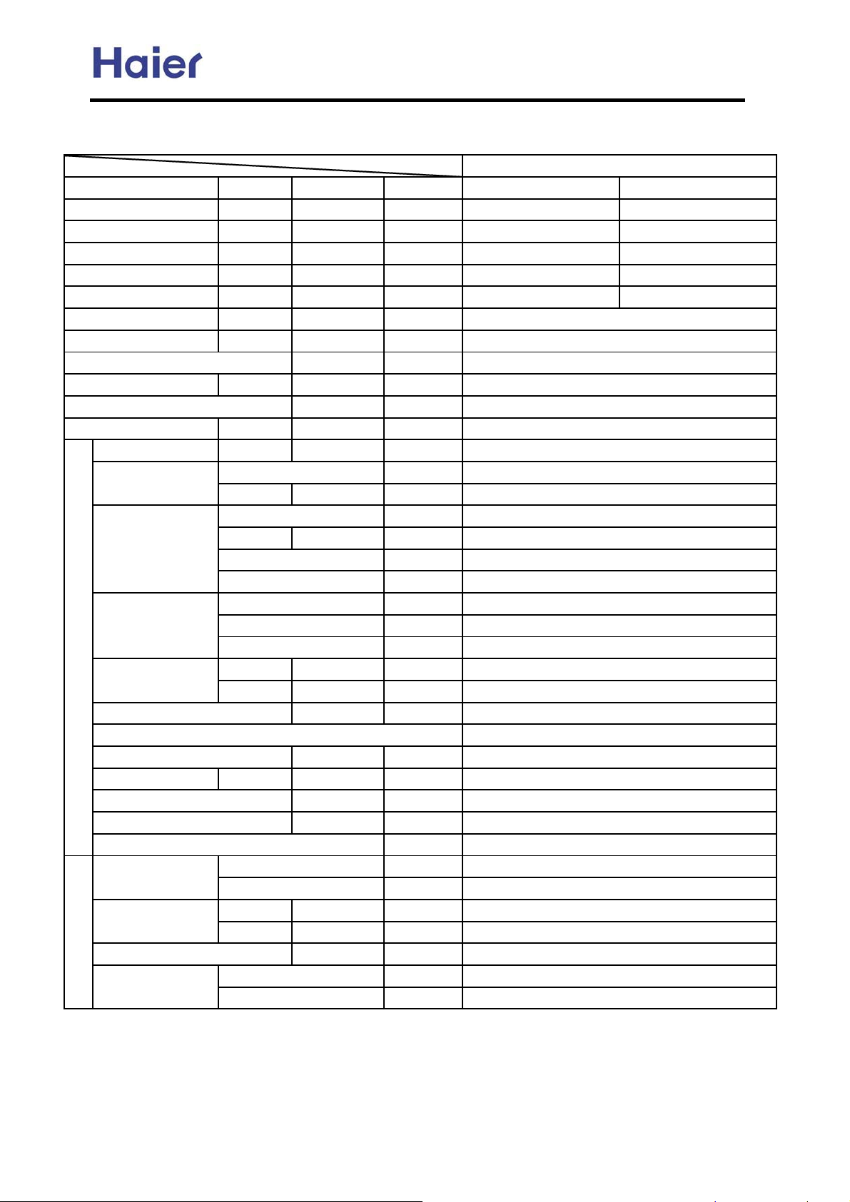
Item Model
Function
Capacity BTU/h
Capacity W
Total power input
Max. power input
EER or COP
W
W
W/W
Power cable
Power source
Running /Max.Running current
NˈVˈHz
A / A
Start Current A
Working frequency range Hz
Fuse A
Unit model (color)
Compressor
Model / Manufacture
Type
Type × Number
Fan
Speed r/min
Fan motor output power kW
Air-flow(H-M-L) m³/h
Type / Diameter mm
Heat exchanger
Dimension
Outdoor unit
Row*fin pintch
Temp. scope
External
Package
˄L×W×H˅
˄L×W×H˅
ć
mm×mm×mm
mm×mm×mm
Refrigerant control method mm/mm
Defrosting
Volume of Accumulator L
Noise level dB(A)
material of reduce noise
crankcase heater power W
Weight (Net / Shipping)
Refrigerant
Type / Charge g
kg / kg
Recharge quantity g/m
Pipe
Liquid mm
Gas mm
PIPING
Connecting Method
Between I.D &O.D
MAX.Drop
MAX.Piping length
m
m
AU48NFIBJA
cooling heating
48000 61000
14000 18000
6000 6000
7000 7000
2.33 3.00
2
4mm
3N~,380-400V,50Hz
cooling: 10.5A/13A heating: 10.5/13A
--
25-95
3.15A 250V AC
AU48NFIBJA (white)
AEV60FCHMT/MITSUBISHI ELECTRIC
SCROLL
AXIAL*2
920±30 r/min/840±40r/min/560±50r/min
65*2
7480
inner grooved copper pipe ¶9.52
2*1.5mm
43-60
1250X948X340
1375X1050X440
EEV
AUTO
--
58
--
40
120/135
R407C/4400
ij9.52 liquid pipe: 65g/mhactual length
¶9.52
¶19.05
flared
outdoor upper: 30, outdoor lower: 20
100
-8-
Page 9
Commercial Air Conditioner Model: AU242FHBIA,
Indoor:
Item model
Cooling capacity Btu/h
Heating capacity Btu/h
Cooling capacity W
Heating capacity W
Dehumidifying capacity
Power source
Running current A
Starting current A
Refrigerant
Noise level(H/M/L) dB(A)
Type × Number
Fan
Heat exchanger
Refrigerant control method
Dimension(L×W×H)
Panel dimension (L×W×
H)
Weight(unit/panel)
Liquid mm (inch)
Piping
Suited area m2
Controller type
Gas mm (inch)
Connection method
Air-flow(H-M-L) m³/h
Fan motor output W
starting mothod
External
Shipping
External
Shipping
Net kg / kg
Shipping kg / kg
10ϋ³×m³/h
NˈVˈHz
mm×mm×mm
mm×mm×mm
mm×mm×mm
mm×mm×mm
AU482FIBIA, AU48NFIBJA
AB092FCBIA AB142FCBIA
9000 12000
11000 14000
2800 3600
3200 4000
1.6 2.1
1PH 220V-230V~ 50HZ 1PH 220V-230V~ 50HZ
-- --
11
R407C R407C
42/--/-- 42/--/--
centrifugal fan×1 centrifugal fan×1
700/--/-- 700/--/--
55 55
PG PG
Combination of wave cranny radiation fin and copper
Capillary + EEV
660×570×260 660×570×260
710×675×360 710×675×360
700×700×60 700×700×60
740×735×105 740×735×105
19.0/2.8 19.0/2.8
23.5/4.8 23.5/4.8
6.35 (1/4") 6.35 (1/4")
12.7 (1/2") 12.7 (1/2")
flared flared
12~23 17~27
remote controller
Item model
Cooling capacity Btu/h
Heating capacity Btu/h
Cooling capacity W
Heating capacity W
Dehumidifying capacity
Power source
Running current A
Starting current A
Refrigerant
Noise level(H/M/L) dB(A)
Type × Number
Fan
Heat exchanger
Refrigerant control method
Dimension(L×W×H)
Panel dimension (L×W×
H)
Weight(unit/panel)
Liquid mm (inch)
Piping
Suited area m2
Controller type
Gas mm (inch)
Connection method
Air-flow(H-M-L) m³/h
Fan motor output W
starting mothod
External
Shipping
External
Shipping
Net kg / kg
Shipping kg / kg
10ϋ³×m³/h
NˈVˈHz
mm×mm×mm
mm×mm×mm
mm×mm×mm
mm×mm×mm
AB182FCBIA
17000
19000
5000
5500
2.1
1PH 220V-230V~ 50HZ
--
1
R407C
42/--/--
centrifugal fan×1
700/--/--
55
PG
Combination of wave
cranny radiation fin and
copper pipe
Capillary + EEV
660×570×260
710×675×360
700×700×60
740×735×105
19.0/2.8
23.5/4.8
6.35 (1/4")
12.7 (1/2")
flared
22~33
remote controller
-9-
Page 10
Commercial Air Conditioner Model: AU242FHBIA,
AU482FIBIA, AU48NFIBJA
Item model
AE072FCBKA AE092FCBKA
Cooling capacity Btu/h 7000 9000
Heating capacity Btu/h 9000 11000
Dehumidifying capacity
Power source
10ϋ³×m³/h
NˈVˈHz
1.2 1.6
1PH 220V-230V 50HZ 1PH 220V-230V 50HZ
Refrigerant R407C R407C
Noise level(H/M/L) dB(A) 36/32/29 36/32/29
Type × Number centrifugal fan×2 centrifugal fan×2
Fan
Air-flow(H-M-L) m³/h 520 / 420 / 300 520 / 420 / 300
starting mothod Relay control Relay control
Heat exchanger
Refrigerant control method
Dimension ˄L×W×H˅
Weight
External
Net kg 18 18
mm×mm×mm
Combination of wave cranny radiation fin and copper
Capillary + EEV
674×225×450 674×225×450
Liquid mm 6.35 6.35
Piping
Gas mm 9.52 9.52
Connection method flared flared
Suited area m2 8~16 11~21
Controller type
wired controller or remote controller
Item model
AE122FCBKA AE142FCBKA
Cooling capacity Btu/h 12000 14000
Heating capacity Btu/h 14000 16000
Dehumidifying capacity
Power source
10ϋ³×m³/h
NˈVˈHz
1.8 2
1PH 220V-230V 50HZ 1PH 220V-230V 50HZ
Refrigerant R407C R407C
Noise level(H/M/L) dB(A) 42/38/32 42/38/32
Type × Number centrifugal fan×2 centrifugal fan×2
Fan
Air-flow(H-M-L) m³/h 650 / 550 / 400 700/ 550 / 400
starting mothod Relay control Relay control
Heat exchanger
Refrigerant control method
Dimension ˄L×W×H˅
Weight
External
Net kg 20 20
mm×mm×mm
Combination of wave cranny radiation fin and copper
Capillary + EEV
828×225×450 828×225×450
Liquid mm 6.35 6.35
Piping
Gas mm 12.7 12.7
Connection method flared flared
Suited area m2 12~23 17~27
Controller type
wired controller or remote controller
-10-
Page 11
Commercial Air Conditioner Model: AU242FHBIA,
z
Z
Z
AU482FIBIA, AU48NFIBJA
Item model
AE182FCBKA AE242FCBKA
Cooling capacity Btu/h 18000 24000
Heating capacity Btu/h 20000 28000
Dehumidifying capacity
Power source
10ϋ³×m³/h
NˈVˈH
Refrigerant
Noise level(H/M/L) dB(A)
2.4 3
1PH 220V-230V 50H
1PH 220V-230V 50H
R407C R407C
48 / 43 / 36 48 / 43 / 36
Type × Number centrifugal fan×2 centrifugal fan×2
Fan
Air-flow(H-M-L) m³/h 1000 /900/700 1000 /900/700
starting mothod Relay control Relay control
Heat exchanger
Combination of wave cranny radiation fin and
Refrigerant control method Capillary + EEV Capillary + EEV
Dimension ˄L×W×H˅
Weight
External mm×mm×mm
Net kg 25 25
Liquid mm 9.52 9.52
Piping
Gas mm 15.88 15.88
Connection method flared flared
Suited area
Controller type
m
2
23~36 32~49
wired controller or remote
controller
wired controller or remote
controller
Item Model
Function
Capacity
Capacity
Dehumidifying capacity
Power cable
Communication cable
Power source
Running current
Unit model (color)
Fan CROSS×1
Heat exchanger
Dimension
Indoor unit
(L×W×H)
Drainage pipe material, diameter mm
Controller type
Refrigerant control
Noise level H/M/L dB(A)
Weight Net / Shipping kg / kg
Refrigerant Type ——
Pipe 6.35
Piping
Connecting method
Type × Number ——
Speed r/min
Motor output power W
Air-flows (H/M/L) m³/h
Type / Diameter mm
Total area m²
Temp. scope
External mm
Package mm
Liquid mm
Gas mm
—— Cooling Heating
BTU/h 18000 20000
W 5200 5800
10ϋ³×m³/h
——
——
N, V, Hz
A / A 0.10 0.10
——
ć
——
——
——
3 × (1.0~1.5mm2 )
2x(0.75~1.25mm2 )
AS182FCBHA (white)
TP2M / 6.35×0.7
cooling: 6~7 / heating: 43~60
Phone type infrared
AS182FCBHA
2.0
1, 220~230, 50
1350/1150/900
25
760/630/560
about 0.15
928×197×265
1025×309×330
PVC, 11.4/16.4
EEV
44/41/38
11/14
R407C
12.7
Flared
-11-
Page 12
Commercial Air Conditioner Model: AU242FHBIA,
(
)
(
)
(
)
AU482FIBIA, AU48NFIBJA
Item Model
Function
Capacity
Capacity
Dehumidifying capacity
10ϋ³×m³/h
Power cable
Communication cable
Power source
N, V, Hz
Running current
Unit model (color)
Fan
Type × Number ——
Speed r/min
Motor output power W
Air-flows (H/M/L) m³/h
Heat exchanger
Type / Diameter mm
Total area m²
Temp. scope
Dimension
Indoor unit
(L×W×H)
External mm
Package mm
Drainage pipe material, diameter mm
Controller type
Refrigerant control
Noise level H/M/L dB(A)
Weight Net / Shipping kg / kg
Refrigerant Type ——
Pipe
Piping
Connecting method
Liquid mm
Gas mm
Item Model
Function
Capacity
Capacity
Dehumidifying capacity
10ϋ³×m³/h
Power cable
Communication cable
Power source
N, V, Hz
Running current
Unit model (color)
Fan
Type × Number ——
Speed r/min
Motor output power W
Air-flows (H-M-L) m³/h
Heat exchanger
Type / Diameter mm
Total area m²
Temp. scope
Dimension
Indoor unit
(L×W×H)
External mm
Package mm
Drainage pipe material, diameter mm
Controller type
Refrigerant control
Noise level H/M/L dB(A)
Weight Net / Shipping kg / kg
Refrigerant Type ——
Pipe
Piping
Connecting method
Liquid mm
Gas mm
AS072FCBHA AS092FCBHA
—— Cooling Heating Cooling Heating
BTU/h 7000 9500 9000 10000
W 2000 2800 2600 3200
1.0 / 1.0 /
——
——
1.0~1.5mm
3 ×
0.75~1.25mm
2x
2
2
1, 220~230, 50
A / A 0.10 0.10 0.10 0.10
——
AS072FCBHA (white) AS092FCBHA (white)
CROSS×1 CROSS×1
1050/900/800 1250/1050/900
25 25
520/410/300 600/500/410
TP2M / 6.35×0.7
about 0.15 about 0.15
ć
cooling: 6~7 / heating: 43~60
795×197×265 795×197×265
880×315×330 880×315×330
PVC, 11.4/16.4
——
——
Phone type infrared
EEV
36/33/29 37/35/30
7.6/10.6 7.6/10.6
R407C
6.35
12.7
——
Flared
AS122FCBHA AS142FCBHA
—— Cooling Heating Cooling Heating
BTU/h 12000 15000 14000 17000
W 3500 4500 4000 5000
1.6 / 2.0 /
——
——
3 × 0.75mm
2x
0.75~1.25mm
2
2
1, 220~230, 50
A / A 0.15 0.15 0.15 0.15
——
AS122FCBHA (white) AS142FCBHA (white)
CROSS×1 CROSS×1
1250/1050/900 1250/1050/900
25 25
630/520/410 640/570/450
TP2M / 6.35×0.7
about 0.20 about 0.20
ć
cooling: 6~7 / heating: 43~60
795×197×265 928×197×265
880×315×330 1025×309×330
PVC, 11.4/16.4
——
——
Phone type infrared
EEV
39/37/30 44/41/38
7.6/10.6 11/14
R407C
6.35
12.7
——
Flared
-12-
Page 13
Commercial Air Conditioner Model: AU242FHBIA,
AU482FIBIA, AU48NFIBJA
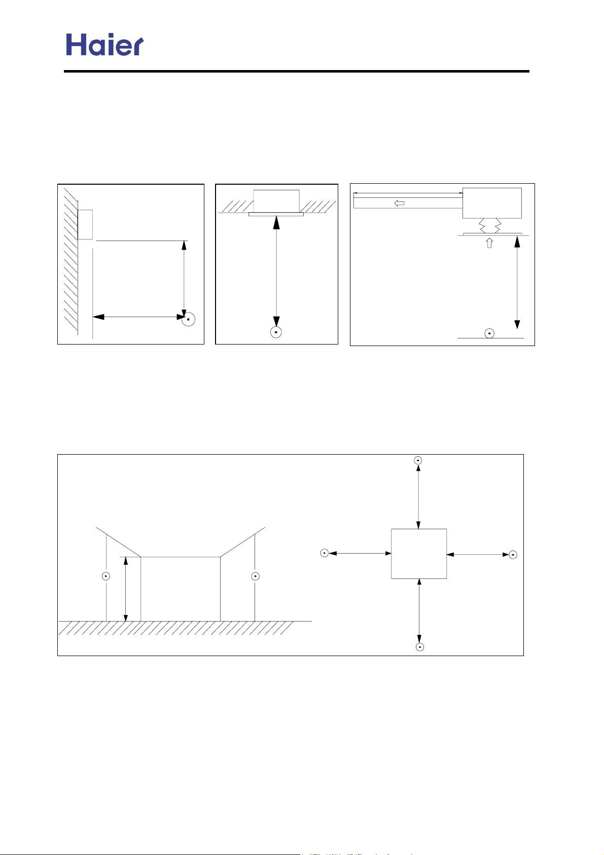
Norminal condition: indoor temperature (cooling): 27 ćDB/19ćWB, indoor temperature (heating): 20 ćDB
Outdoor temperature(cooling): 35ćDB/24ćWB, outdoor temperature(heating): 7 ćDB/6ćWB
The noise level will be measured in the third octave band limited values, using a Real Time Analyser calibrated sound
intensity meter. It is a sound pressure noise level. The detailed method please refer to the following information:
Installation state: the unit should be placed on the flat floor or be mounted in horizontal direction.
Testing method:
mounting-on-wall unit: built-in-ceiling unit: duct unit without auxiliary duct:
2m
duct
0.8m
1.4m
1.4m
1m
outdoor unit:
1.air outlet from side: the noise level is the average sound pressure level measured from front, left, right
directions.
2.air outlet from top: the noise level is the average sound pressure level measured from front, back, left,
right directions.
measured point:
H ( height to the ground) = (h (unit height) + 1m) /2
and, it is 1m to each side.
1m
1m
1m
h
Note: Ĵ is the real
time analyser position
1m
-13-
Page 14
Commercial Air Conditioner Model: AU242FHBIA,
AU482FIBIA, AU48NFIBJA
3. Safety precaution
Carefully read the following information in order to operate the airconditioner correctly.
Below are listed three kinds of Safety Cautions and Suggestions.
WARNING!
CAUTION!
INSTRUCTIONS: These information can ensure the correct operation of the machine.
Be sure to conform with the following important Safety Cautions.
The Safety Cautions should be at hand so that they can be checked at any time when needed.
If the conditioner is transferred to the new user, this manual should be as well transferred to the new user.
Incorrect operations may result in severe consequences of death or serious injuries.
Incorrect operations may result in injuries or machine damages; in some cases may
cause serious consequences.
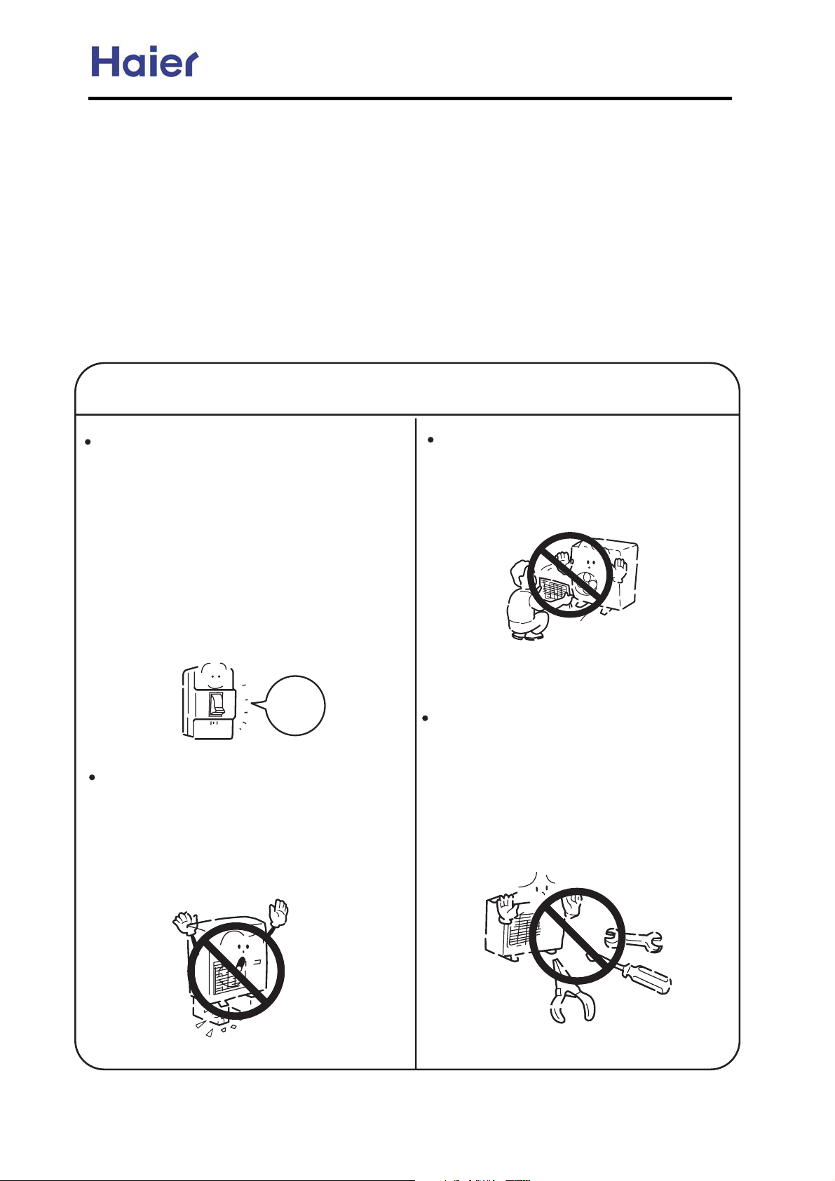
WARNING!
If any abnormal phenomena is found
(e. g.smell of firing), please cut off the
power supply immediately, and contact
the dealer to find out the handling
method.
In such case, to continue using the
conditioner will damage the conditioner,
and may cause electrical shock or fire
hazard.
Don't dismantle the outlet of the
outdoor unit.
The exposed fan is very dangerous
which may harm human beings.
switch
off
After the unit being used for a long time,
the base should be checked for any
damages.
If the damaged base is not repaired, the
unit may fall down and cause accidents.
When the unit needs maintenance and
repairment, please call dealer to handle it.
Incorrect maintenance and repairment
may cause water leak, electrical shock
and fire hazard.
-14-
Page 15
Commercial Air Conditioner Model: AU242FHBIA,
AU482FIBIA, AU48NFIBJA
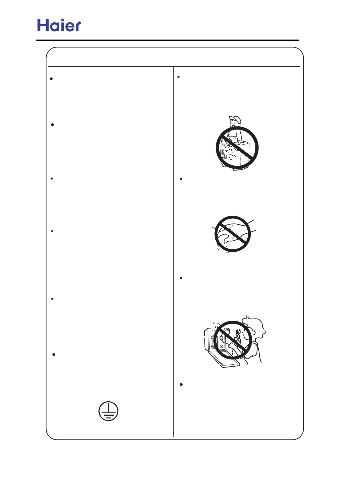
WARNING!
Installed electrical-leaking circuit
breaker.
It easily cause electrical shock without
circuit breaker.
Air-conditioner can't be installed in
the environment with inflammable
gases because the inflammable gases
near to air-conditioner may cause fire
hazard.
Please let the dealer be responsible for
installing the conditioner.
Incorrect installation may cause water
leak, electrical shock and fire hazard.
Call the dealer to take measures to
prevent the refrigerant from leaking.
Nothing or nobody is permitted to
placed on or stand on outdoor unit.
The falling of goods and people may
cause accidents.
Don't operate the air-conditioner with
damp hands.
Otherwise will be shocked.
If conditioner is installed in a small
room be sure to take every measure in
order to prevent suffocation accident
even in case of refrigerant leakage.
When conditioner is removed or
reinstalled, dealer should be responsible
for them.
Incorrect installation may cause water
leaking, electrical shock and fire hazard.
Connect earthing wire.
Earthing wire should not be connected to the gas pipe, water pipe,
lightning rod or phone line, in-correct
earthing may cause shock.
Only use correctly-typed fuse.
May not use wire or any other materials
replacing fuse, other-wise may cause
faults or fire accidents.
Use discharge pipe correctly to ensure
efficient discharge.
Incorrect pipe use may cause water
leaking.
Earthing
-15-
Page 16
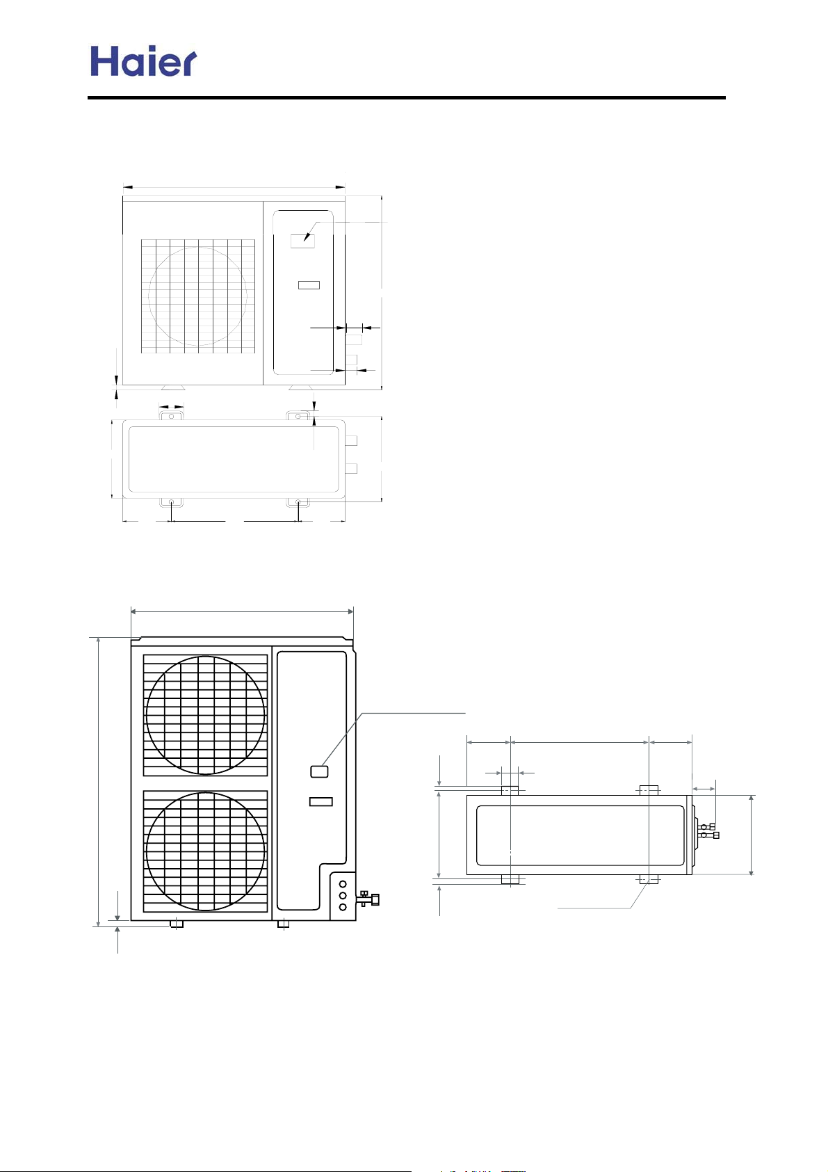
4. Net dimension
AU242FHBHA
948
Commercial Air Conditioner Model: AU242FHBIA,
AU482FIBIA, AU48NFIBJA
Power wiring terminal
840
70
25
340
AU48*
184
70
580
948
55
18
184
380
Power wiring Terminal
184 184
580
1250
25
18
380
18
-16-
70
55
340
Screw Hole
(4xM10)
Page 17
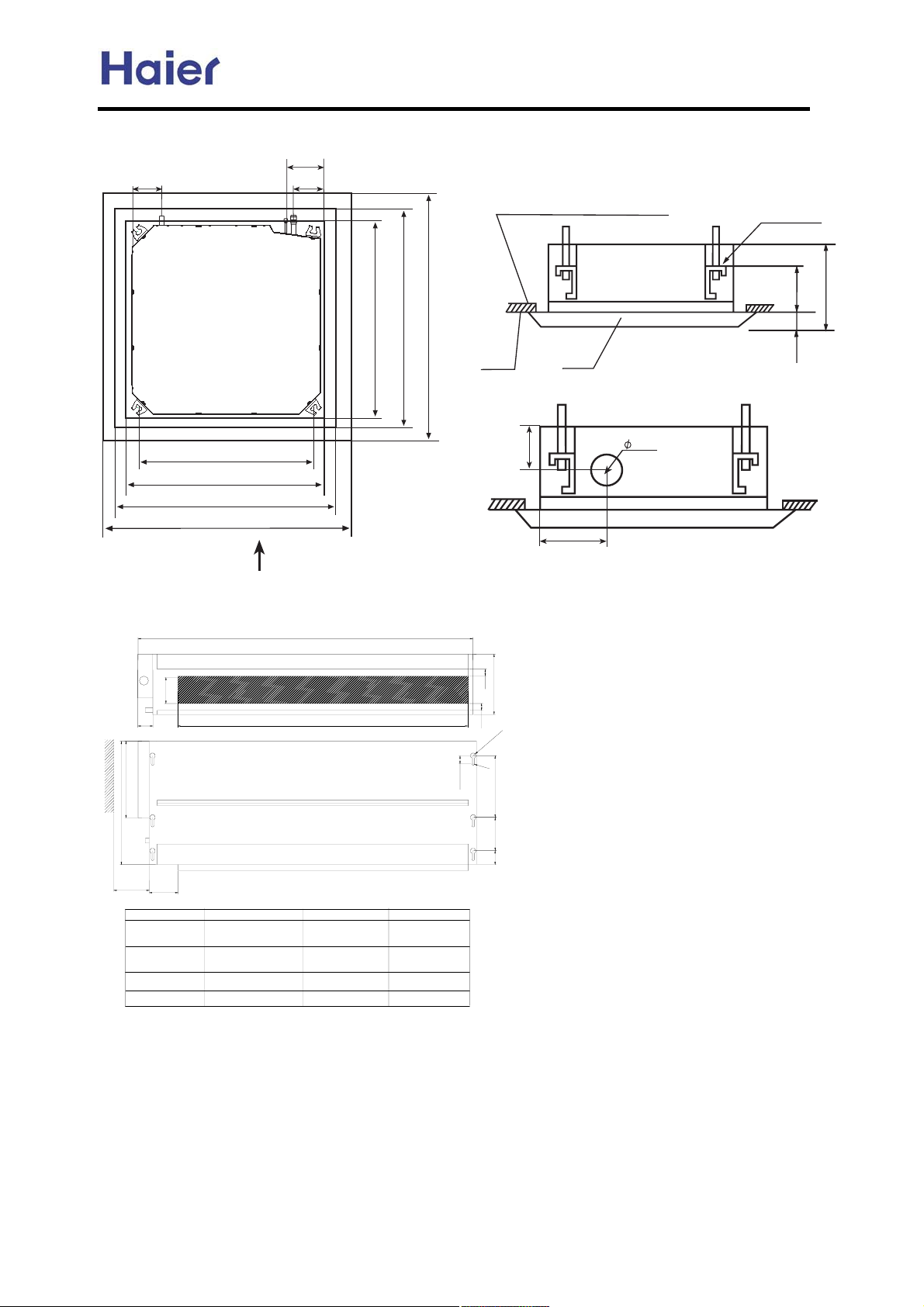
AB** Cassette unit:
B9
LXIQTIOM VQVM
:;9
A9
OIY VQVMRQW[QL VQVM
Commercial Air Conditioner Model: AU242FHBIA,
AU482FIBIA, AU48NFIBJA
U\MXRIVML LQYZITKM JMZ]MMT ZPM KMQRQTO
ITL ZPM VITMRC ;>SS
Y[YVMTYQUT PURLMX
:>9SS
<;9SS
><>SS 7JMZ]MMT Y[YVMTYQUT VURMY8
>@9SS 7QTLUUX [TQZ LQSMTYQUT8
?>9SS 7KMQRQTO UVMTQTO LQSMTYQUT8
@99SS 7VITMR LQSMTYQUT8
GFEH D
AE** Ceiling concealed unit
100
54
240
C
>@9SS 7QTLUUX [TQZ LQSMTYQUT8
?>9SS 7KMQRQTO UVMTQTO LQSMTYQUT8
@99SS 7VITMR LQSMTYQUT8
KMQRQTO
:A9
VITMR
B>
?9SS
NXMYP IQX PURM
:=9
GFEH D
b
25
225
a
25
10
R
R
5
30
29(5
unit model
AE072FCBKA
AE092FCBKA
AE122FCBKA
AE142FCBKA
AE182FCBKA
AE242FCBKA
55
93
615
704
858
990
a
b
650
800
1020
1350
c
452
452
452
452
-17-
Page 18
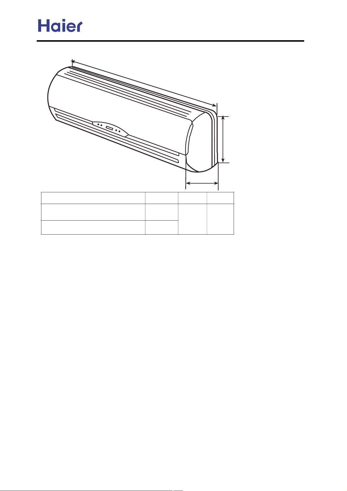
AS** series
Commercial Air Conditioner Model: AU242FHBIA,
AU482FIBIA, AU48NFIBJA
O
:=DAI
P
Q
FH@AE
AS072FCBHA AS092FCBHA
AS122FCBHA
AS142FCBHA AS182FCBHA
=
462
6/5
>
/32
?
.64
-18-
Page 19
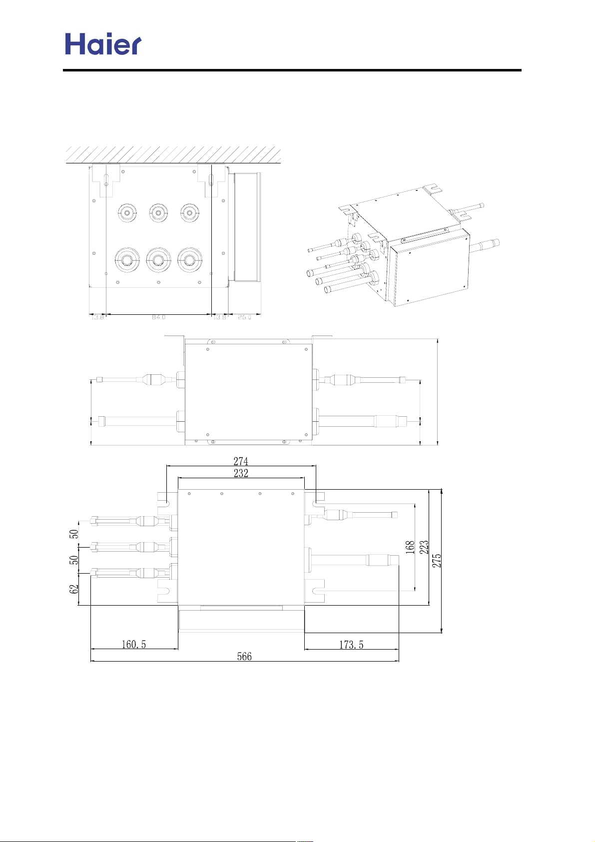
Commercial Air Conditioner Model: AU242FHBIA,
Dimensions for MP2A, MP3A:
Installation on the horizontal ceiling:
horizontal ceiling
AU482FIBIA, AU48NFIBJA
-19-
Page 20
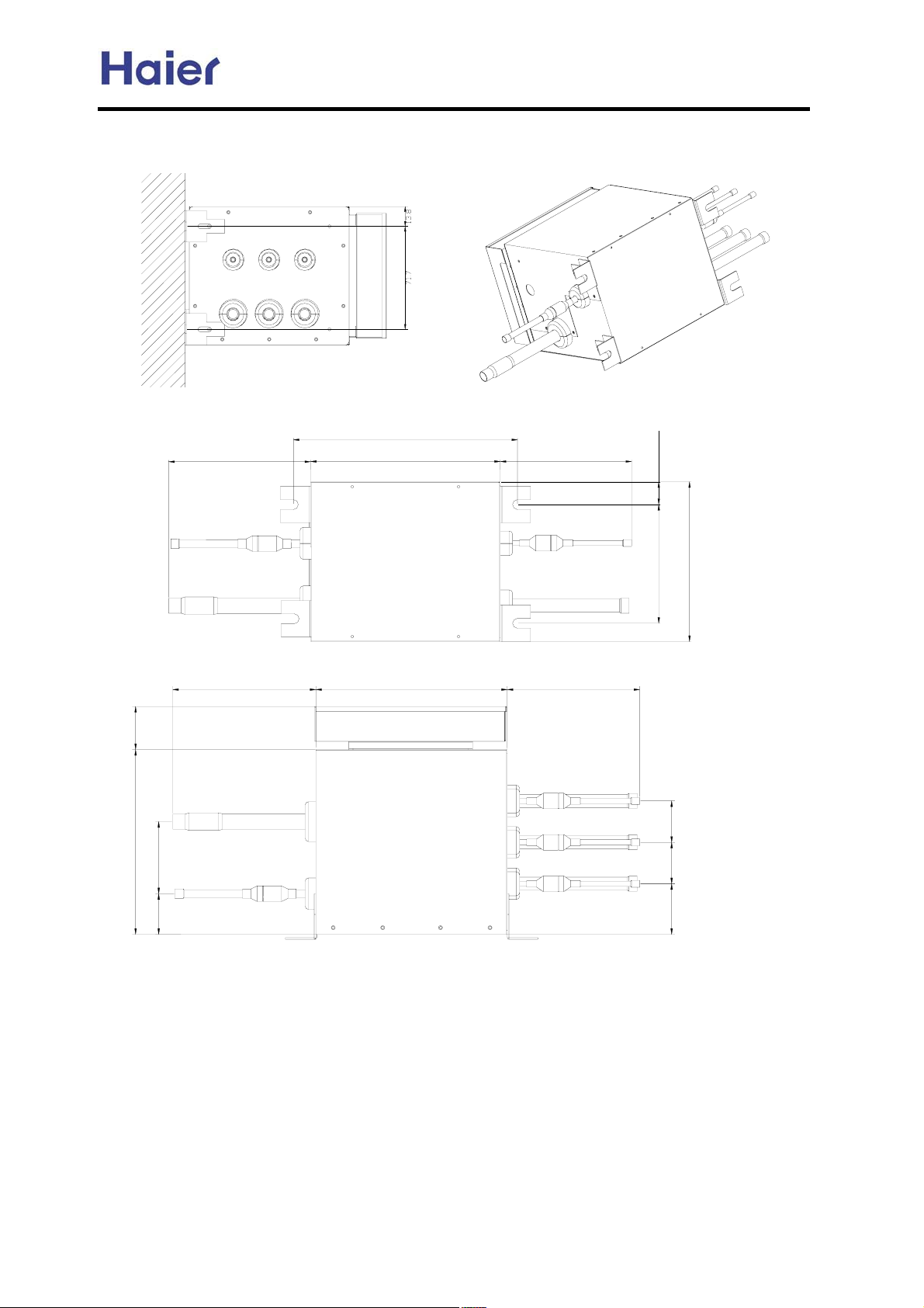
Installation on the vertical wall (adjust the installation position by fixing holder):
vertical wall
Commercial Air Conditioner Model: AU242FHBIA,
AU482FIBIA, AU48NFIBJA
-20-
Page 21
Commercial Air Conditioner Model: AU242FHBIA,
5. Installation Instructions
5.1 Piping dimension chart
AU482FIBIA, AU48NFIBJA
model
liquid pipe gas pipe
mm inch mm inch
AU24 9.52 3/8" 15.88 5/8"
AU48 9.52 3/8" 19.05 3/4"
AB09 6.35 1/4" 12.7 1/2"
AB14 6.35 1/4" 12.7 1/2"
AB18 6.35 1/4" 12.7 1/2"
AE07 6.35 1/4" 9.52 3/8"
AE09 6.35 1/4" 9.52 3/8"
AE12 6.35 1/4" 12.7 1/2"
AE14 6.35 1/4" 12.7 1/2"
AE18 9.52 3/8" 15.88 5/8"
AE24 9.52 3/8" 15.88 5/8"
AS07 6.35 1/4" 12.7 1/2"
AS09 6.35 1/4" 12.7 1/2"
AS12 6.35 1/4" 12.7 1/2"
AS14 6.35 1/4" 12.7 1/2"
AS18 6.35 1/4" 12.7 1/2"
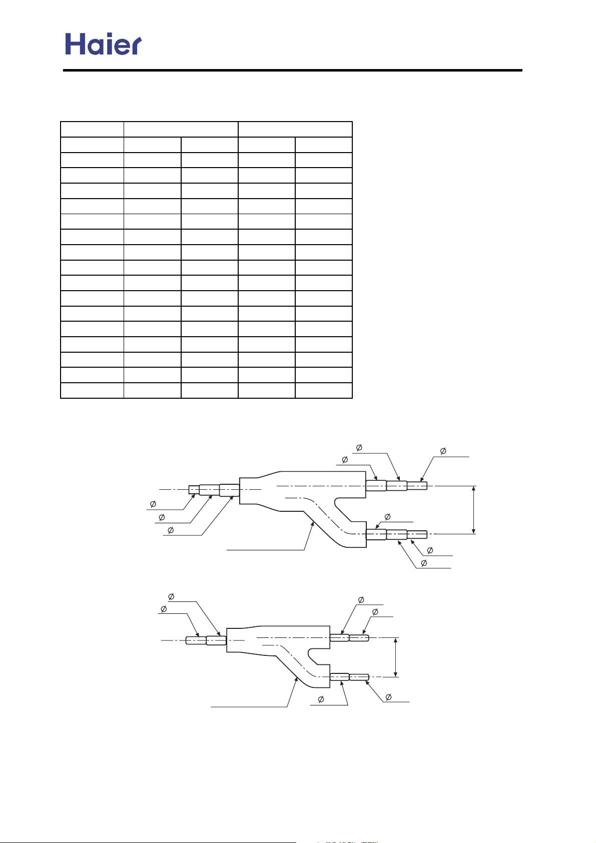
5.2 Y-shape manifold pipe
model: FQG-B120
<gas side>
9.52
12.7
15.88
<liquid side>
9.52
6.35
heat preservation
material
heat preservation
material
12.7
15.9
12.7
12.7
9.52
15.88
75
9.52
9.52
75
9.52
12.7
Dimension is the out diameter connecting to the tubing.
-21-
Page 22
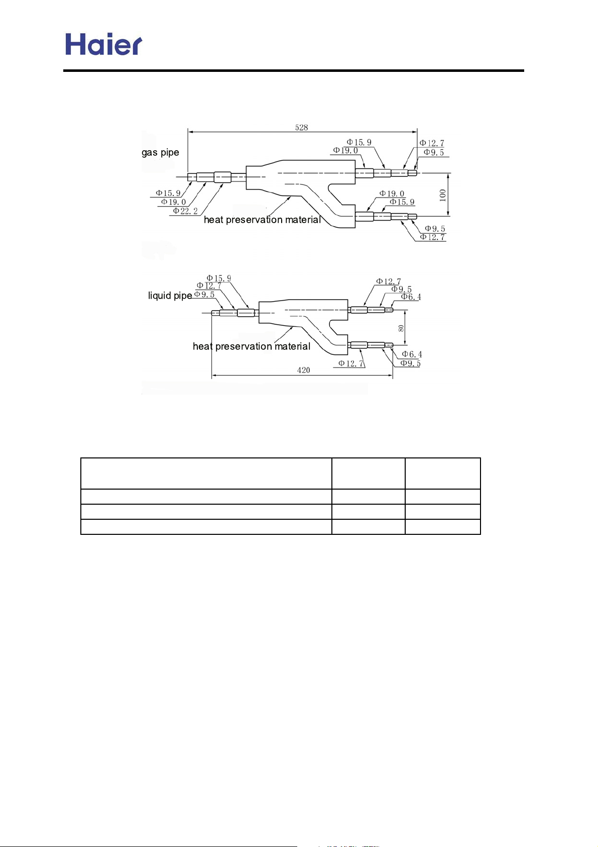
FQG-B180
g
Commercial Air Conditioner Model: AU242FHBIA,
AU482FIBIA, AU48NFIBJA
Refrigerant pipes between manifold pipes
Total refrigerating amount of indoor unit
Gas side Liquid side
roup after the manifold pipe
Less than 38220Btu/h 15.9 9.52
38220~61157Btu/h 19.05 9.52
61157~126137Btu/h 25.4 12.7
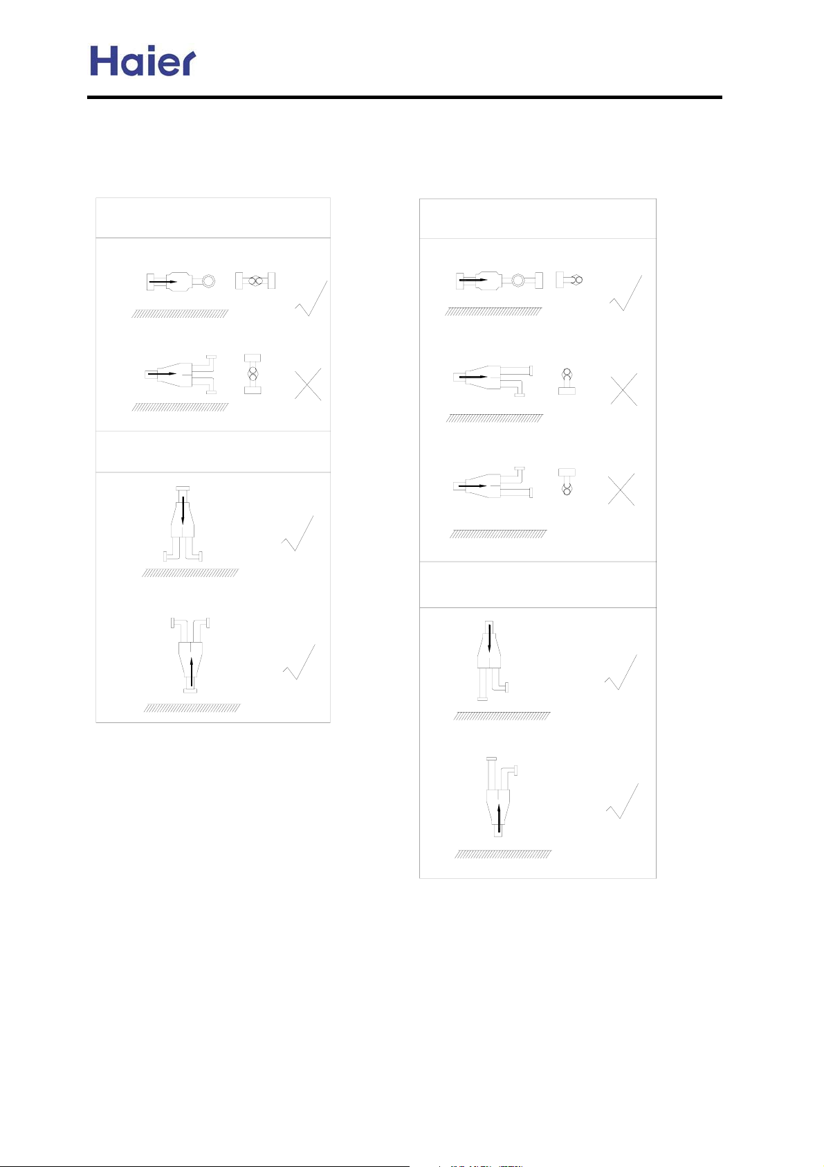
Note: 1. Y-shape manifold pipe can be placed in horizontal or vertical
direction
2. The manifold pipes must be welded with hard-solder
3. Pay attention to cut off the unnecessary part from its middle
parts of each joint, and to remove burr.
-22-
Page 23
Commercial Air Conditioner Model: AU242FHBIA,
AU482FIBIA, AU48NFIBJA
In the file, the figure marked with "Ĝ" is permitted, and the figure marked with "h" is prohibited.
You can confirm the position according to the actual condition.
The refrigerant flow direction is always from the collective side to the divided side.
horizontal
vertical
floor surface
floor surface
floor surface
horizontal
floor surface
floor surface
floor surface
vertical
floor surface
floor surface
floor surface
-23-
Page 24
Commercial Air Conditioner Model: AU242FHBIA,
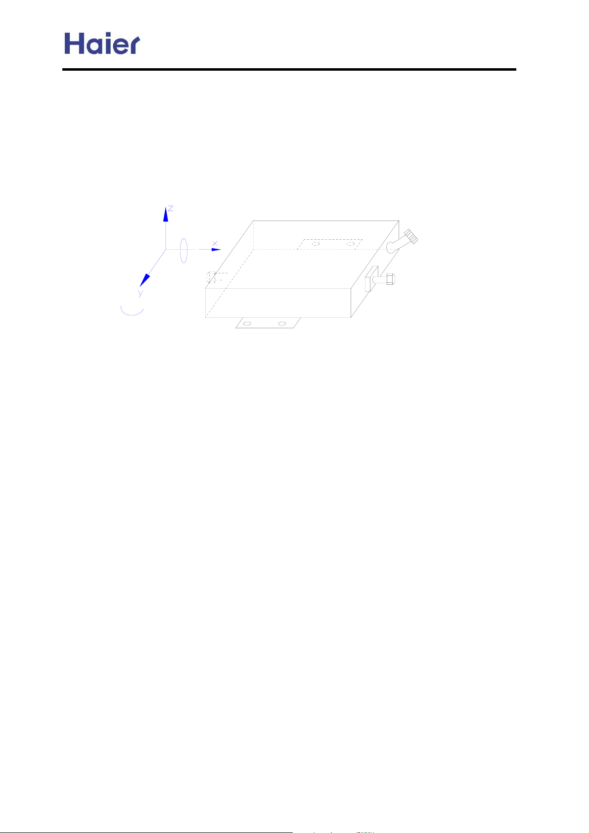
5.3 Instructions for the Electrical Expansion Valve Boxes
The E.E.V.B. general information for the C-MRV and H-MRV indoor units.
1. Installation position
AU482FIBIA, AU48NFIBJA
0°
360°
180°
Z: vertical direction
X, Y: horizontal direction
2. Installation place
The box should be installed where the place:
a. do not have vibrations;
b. easy to piping with the indoor and the outdoor unit, and the distance from the box to the indoor unit
should not exceed a certain value;
c. do not have a heat or steam source nearby;
d. should be sunless and be dry;
e. should be well ventilated and rainproof;
0°
wiring connector
liquid pipe in/out
f. do not have a strict noise restriction, because when working the box may make some noise;
-24-
Page 25
Commercial Air Conditioner Model: AU242FHBIA,
AU482FIBIA, AU48NFIBJA
5.4 MP2A, MP3A Installation Requirement
1. Cautions
1.1 The place should be strong enough to support this equipment, no vibrantion;
1.2 The place where is convenient to install the indoor unit, outdoor unit and the refrigerant pipe, and
the length of the pipe is in the permitted range;
1.3 No heat source and gas source nearby;
1.4 The place has enough space for installation and maintenance;
1.5 Donpt installation in the place in the state of high temperature and high humidity for a long time;
1.6 The place with good ventilation, no direct sunshine and rain;
1.7 Donpt install the unit near the bedroom because of the refrigerant flow noise;
Please refer to the cautions and warnings in the operation manual about the other safety cautions.
2. Installation Method
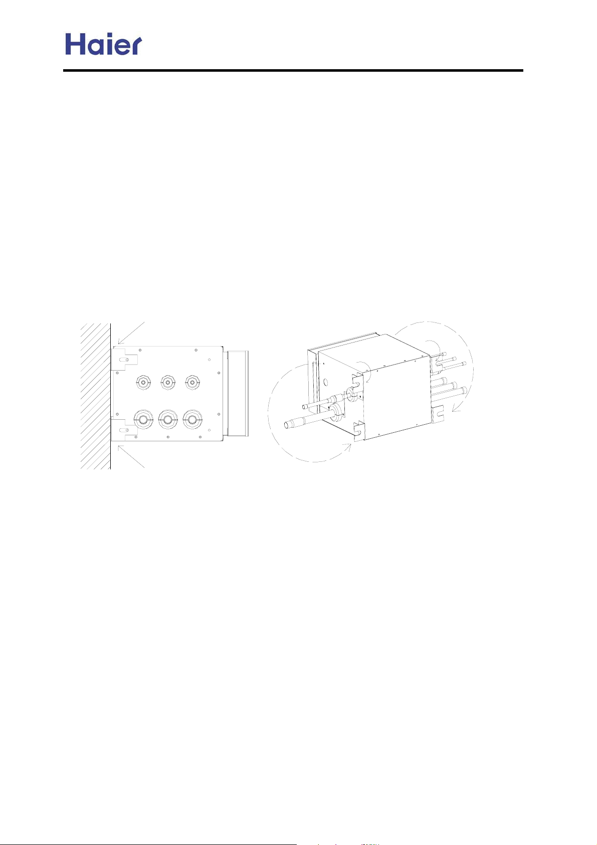
2.1 MP2A, MP3A can be installed on the horizontal ceiling or the vertical wall by adjusting the fixing
holder. The maintenance plate should be installed on the place easy to maintain and near the place,
there should be checking hole with 600mm*600mm (adjust the fixing holder as below figure).
vertical wall
2.2 The equipment has been dealt with the EPS heat insulation material, so the drainage pipe needs
not any other treatments.
2.3 The pipe connected to indoor is led from the branch pipe of the equipment. The gas pipe
diameter can realize to match with different diameters by the changing pipe according to the
indoor pipe diameter request.
2.4 In installation, the equipment gradient should be in the range of 5¤, or it may cause electronic
expansion valve body in the equipment leakage or the other bad control failure.
2.5 Bolt, screw cap and gasket to fix the equipment will not be supplied by factory.
3. Wiring Connection
3.1 The wire and refrigerant pipe must be connected to the corresponding place (refer to marks on
the equipment and the terminal block as 1,2,3).
3.2 Wiring diagram is sticked on the back of cover plate, and the wiring must be performed
according to the wiring diagram, or the control will be bad or indoor and the equipment will be
damaged.
3.3 After wiring, the wires must be fixed with the wire clip firmly, in case that the electric control parts
are damaged or occurs person injury.
-25-
Page 26
Commercial Air Conditioner Model: AU242FHBIA,
AU482FIBIA, AU48NFIBJA
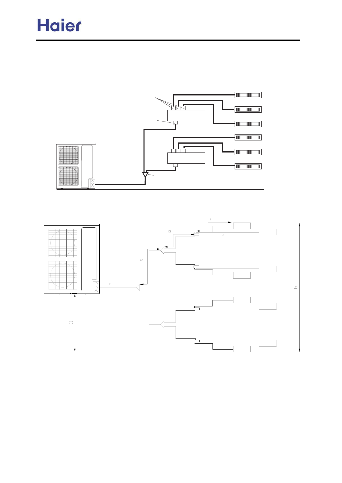
5.5 Connecting figure:
670 ;9E := LJ=< >FI KMF AE<FFI LEAKJ- GC=9J= ;FE>AID K@= 670 HL9EKAKO 9;;FI<AE? KF K@= 9;KL9C AE<FFI LEAKJ/
671 ;9E := LJ=< >FI K@I== AE<FFI LEAKJ- GC=9J= ;FE>AID K@= 671 HL9EKAKO 9;;FI<AE? KF K@= 9;KL9C AE<FFI LEAKJ/
5EJK9CC9KAFE D=K@F< AJ :=CFM- M@A;@ FECO K9B=J 671 9J 9E =N9DGC=/ 7C=9J= G9O 9KK=EKAFE K@9K K@= ?9J GAG=J
AEJK9CC9KAFE AJ 9J K@= J9D= 9J K@= ;FE<AKAFE MAK@FLK 670+671,/
AE<FFI CAHLA< GAG=
FLK<FFI CAHLA< GAG=
8.J@9G= D9EA>FC< GAG=
Piping length and drop between units
Haier
QRP
QRP
AE<FFI 2
AE<FFI 3
AE<FFI 4
AE<FFI 20
AE<FFI 30
AE<FFI 40
+
-26-
Page 27
Commercial Air Conditioner Model: AU242FHBIA,
AU482FIBIA, AU48NFIBJA
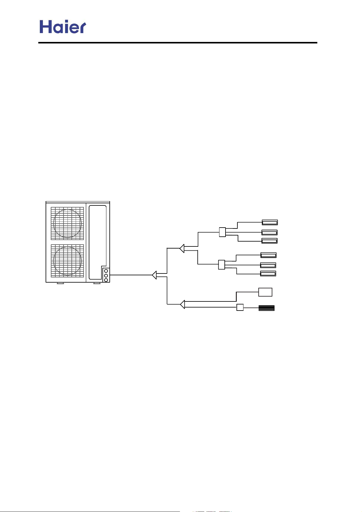
1) When connected with 8 units,indoor units refer to <admissible combination examples>
2) Total length=l1+l2*2+l3*4+l4*4+l5*4<=100m
3) Max. piping length =(l1+l2+l3+l5)<=70m
4) Max. piping length between the indoor unit and the first branch pipe<=30m
5) Max. drop between outdoor unit and indoor unit: H<=30m(indoor above
outdoor);H<=20m(indoor below outdoor)
6) Max. drop between the two indoor units : h<=10m
7) Expansion valve is less than 15m to its corresponding indoor unit
8) Only wall mounted types are connected with expansion valves.
9) The expansion valves of different indoor models are different.
10)The first branch pipe must use FQG-180,the others use less than it.
Combination example:
8 by 1:
Haier
AE07
AE07
MP3A
MP3A
EEV
AE07
AE07
AE07
AE07
AB09
AS07
Note:
1.AU24 can connect with max. 5 indoor units, and AU48 can connect with max. 8 indoor units, but pay
attention that the total indoor capacity can not exceed 130% of outdoor cooling capacity.
2.
The ceiling concealed unit must connect with the outdoor unit through the MP2A or MP3A; the wall mounted
unit must connect with the outdoor unit through the exterior EEV box; while for the cassette unit, because it has
the built-in EEV, so it need not anything and it can connect to outdoor directly.
-27-
Page 28
Commercial Air Conditioner Model: AU242FHBIA,
AU482FIBIA, AU48NFIBJA
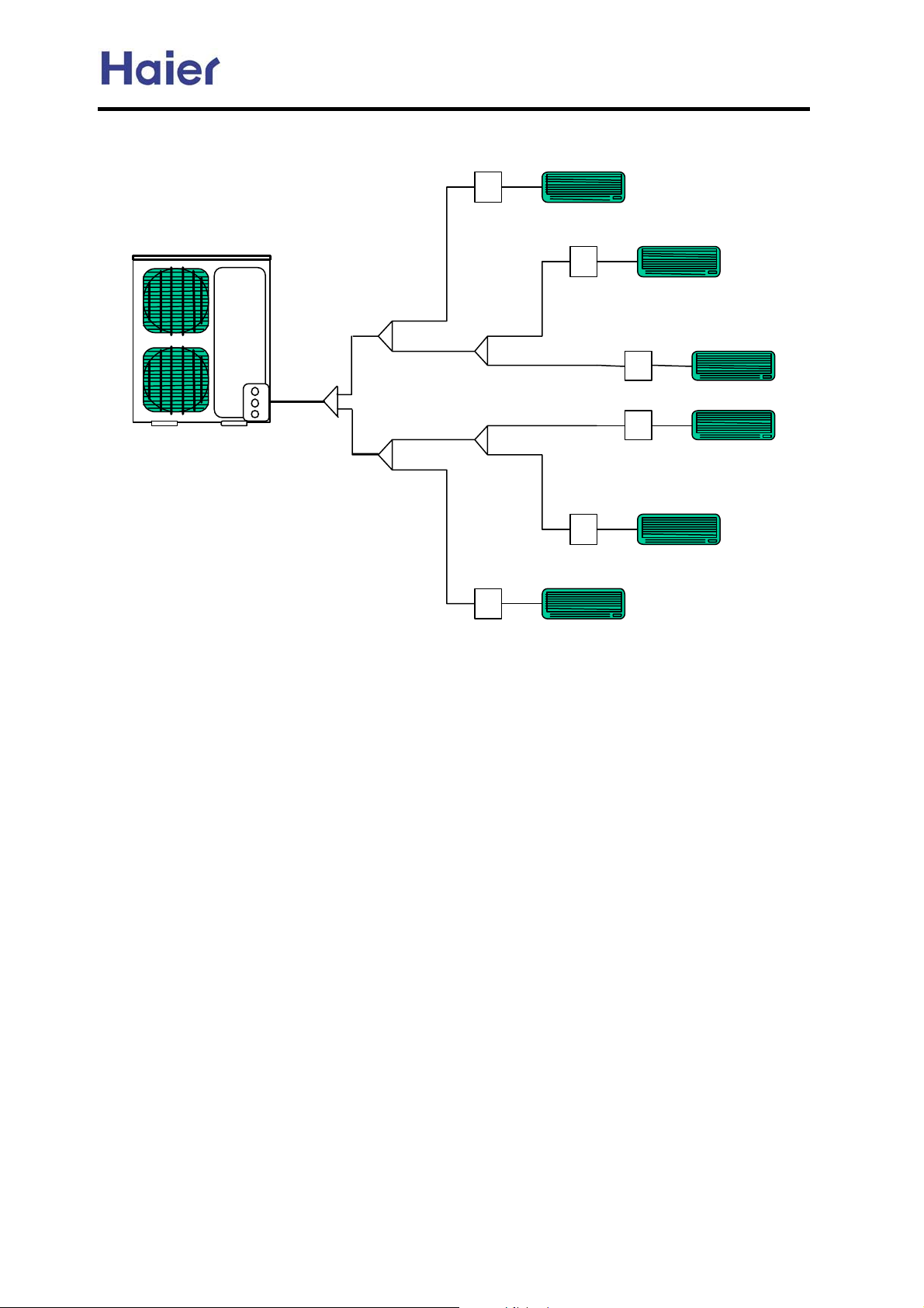
6 by one
AU48-
AS09 (or other 9000BTU units)
AS09 (or other 9000BTU units)
Haier
AS09 (or other 9000BTU units)
AS09 (or other 9000BTU units)
AS09 (or other 9000BTU units)
EEV
AS09 (or other 9000BTU units)
-28-
Page 29
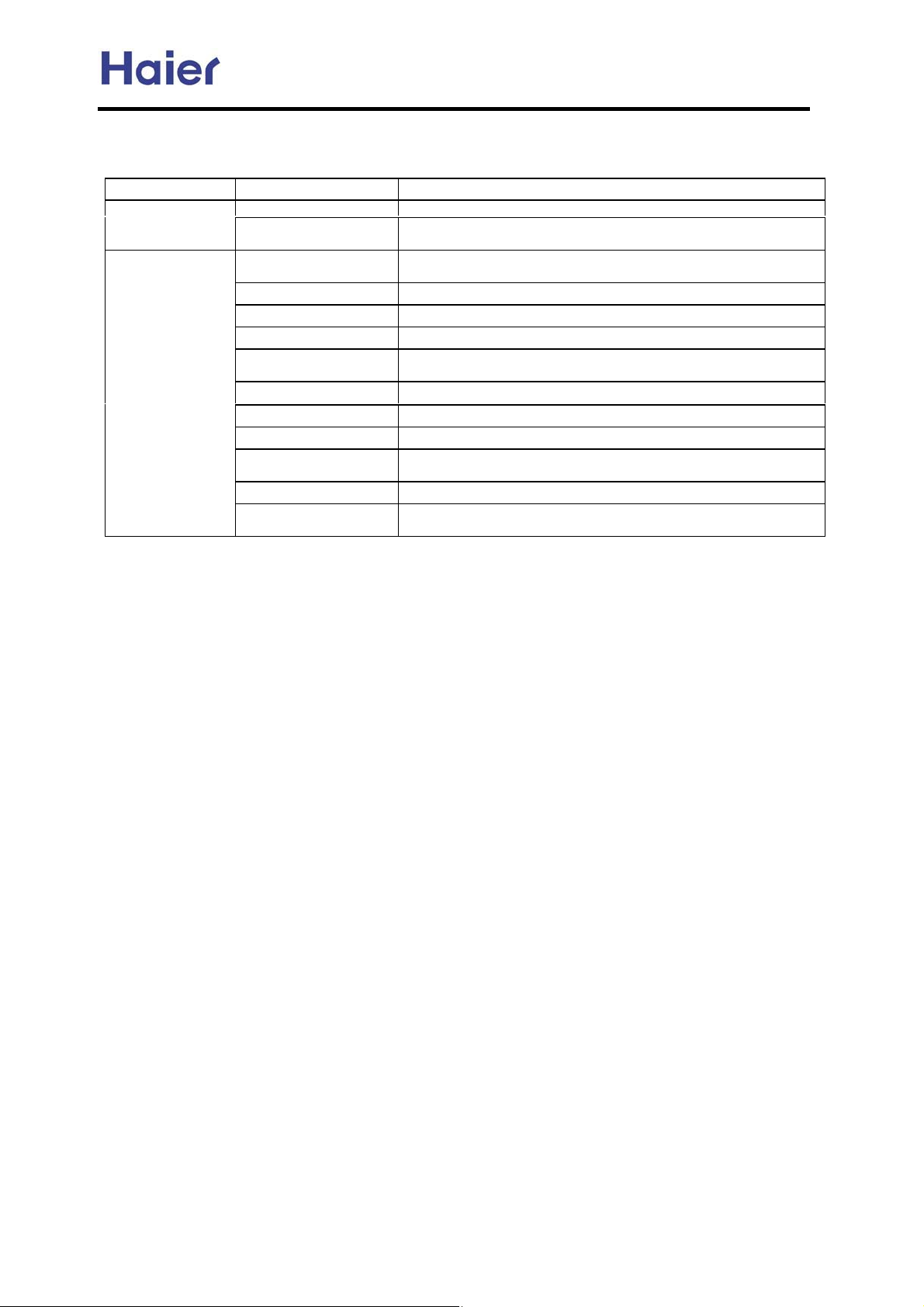
Commercial Air Conditioner Model: AU242FHBIA,
5.6 The Order of Installation Work
AU482FIBIA, AU48NFIBJA
Item
Before installation Work division -to ascertain the person responsible for installation of pipes and wiring
Work
Installation of indoor and
Work Main points
Make installation
diagram
outdoor unit
Refrigerant pipe work -Pay attention to dry, clean and seal
Drain pipe work -Slant downward
Heat insulation work -No gaps in the joint of heat insulation material
Wiring work (control
wire, power cord)
Set every set switch -Should be complied with control wiring system diagram
Airtight test -Close all the gas, liquid valves
Vacuum drying -Should the vacuum pump that can reach 200Pa vacuity
Additional refrigerant -Write down the additional refrigerant amount on the outdoor unit body
Test run adjustment -Do test run to indoor unit one by one to verify if there is wrong pipes
Training of use and
maintenance
-to ascertain the pipe installation dimension and position of electronic
expansion valve, to make control wiring system diagram
-to prevent the ventilation from short circuit and guarantee repair space
-Choose the proper wire and cord
and record table
-Explain to user, simultaneously provide all the documents
The above work order is general knowledge, they may be changed to be complied with the
specific work site.
5.7 Attentive matters of safety
Before installing, do read this [Attentive matters of safety] carefully to guarantee the
proper installation.
The below attentive matters are divided into [warning] and [note] two parts. When the
wrong installation occur, it is very possible death and severe injury and other serious
accidents will happen. For those items are listed in [warning] part. But even the items
listed in [note] part can also cause serious accidents. Above all, both the two parts are
very important contents related to safety, so they must be obeyed.
After installation, do test run to verify everything is normal, after that please explains the
use method and maintenance method to the user according to the operation manual.
Additionally, give the installation manual together with operation manual to the user and
ask them to keep them properly.
Warning
The distributing shop, where you bought the air conditioner, or the specified shops shall
do the installation work. If you do the installation work by yourself, the improper
installation will cause water leakage, electric shock fire and other accidents.
The installation work shall be in line with what the installation manual specified. If
installation is not proper, water leakage, electric shock, fire and other accidents will
occur.
Install the air conditioner to a place where can definitely stand its weight. Places not firm
enough will cause drop down of unit resulting in body hurt.
The installation work shall be preventive to typhoon and earthquake. If the installation
-29-
Page 30
Commercial Air Conditioner Model: AU242FHBIA,
AU482FIBIA, AU48NFIBJA
work is not met with the requirements, overturn of the unit will occur resulting in
accidents.
The wiring work shall be done by a qualified person and referred to the “technical
standard of electric equipment”, “indoor wiring regulation” and what the manual
specified. Do use special circuit. If the capacity of the circuit is not enough or bad work,
electric shock, fire and other accidents will happen.
Using the specified cable to do wiring work and connecting firmly and properly. Fix the
connecting part of the terminals to prevent it from the external force. Improper
connection and fixing will cause heating and fire etc. accidents.
Wiring shall be kept in correct shape avoiding extrusion. After installation, the electric
box cover and the external panel shall not nip the wire. Improper installation will cause
heating and fire etc. accidents.
When setting or moving the air conditioner do not let the air and things alike get into the
refrigeration system except the specified refrigerant. If air and other things enter,abnormal
high pressure will occur, which easily cause break and body injuries etc.
When installing, do use the accessories or specified parts. If not using the parts specified
by our company, water leakage, electric shock, fire and refrigerant leakage will occur.
Do not lead the drainpipe to drain where the sulfur gas may be involved. Otherwise, the
poisonous gas will enter into the indoor.
During installation, if refrigerant leakage occurs, do the ventilation work immediately. As
soon as the refrigerant gas meets fire, poisonous gas will be produce. If the refrigerant gas
enters into room and meet the air blowing heater, heater or stove etc. fire source, the
poisonous gas may be produced. After installation, confirm there is no leakage of
refrigerant.
Do not install the unit in a place where the combustible gas may be leaked. In any case
the combustible gas leaks and accumulated around the unit, fire accident will occur.
Do heat insulation work to the refrigerant gas pipes and liquid pipes to reach the purpose
of heat preservation. If the heat insulation measure is not sufficient, water generated by
condensing dew will drip leading to wet the floor and indoor articles.
Do not damage the power line or change it arbitrarily to avoid occurrence of fire or
electric shock.
Do not extend the power line or using other electric appliance in the same power
receptacle to avoid fire or electric shock.
Note
Do grounding work. Do not connect the grounding wire to gas pipe, tap, lighting rod or
telephone line. Improper grounding will cause electric shock.
In some places the electric leakage breaker shall be installed. If do not install the breaker,
electric shock may occur.
After installation, power on to do electric leakage detecting test.
-30-
Page 31
Commercial Air Conditioner Model: AU242FHBIA,
g
t
n
g
g
m
g
r
5.8 Special Work and Main Points in Installation
Warning
AU482FIBIA, AU48NFIBJA
Durin
leakage occurs, take ventilatio
measurement immediately.
As soon as the leaked refri
generate.
installation, if refrigeran
erant
as meets fire, poisonous gas will
After finishing installation, confir
the refrigerant gas does not leak.
If the refri
room, once it meets heater, burne
and gas stove etc. fire source, the
poisonous gas will generate.
erant gas leaks in the
A. Choosing of pipes
According to the following indoor unit and outdoor unit installation diagram to choose the
material and size of pipes and branch pipes.
B. Connection of pipes
1 Method of pipe connection
a. The pipe shall be as short as possible to guarantee efficiency.
b. Daub the refrigerant oil on the connection and flare nut.
c. When bending the pipes, give the roundness as large as possible, to avoid crashing the
pipes.
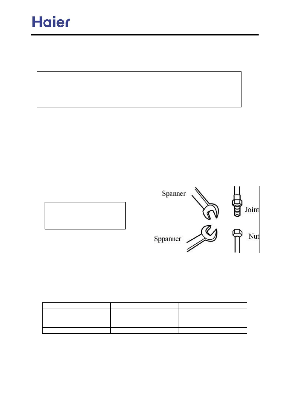
d. To connect the pipe, fit the center and screw the nut with hand, then use spanner or
torque wrench to tighten it. The fastening torque as shown in below table. As shown in
figure.
e. Be careful alien matters, such as sands,
water etc. shall not enter the pipes.
Forced fastening without
careful centering may damage
the threads and cause gas
2. Welding of pipes
a. In welding, the nitrogen shall be used to
avoid oxidation of the pipe inner part.
b. The refrigerating pipe shall use clean
new pipes. When working, it shall take steps to prevent water and dust from entering.
c. When loosening and tightening the nuts, two spanners shall be used. If using one
spanner, it can not reach the desired degree of tightness.
Using the specified fastening torque to fasten nuts.
Pipe diameter (mm) Installation torque (N.M.) Fastening torque (N.M.)
6.35 11.8 (1.2kgf.m) 13.7 (1.4kgf.m)
9.52 24.5 (2.5kgf.m) 29.4 (3.0kgf.m)
12.7 49.0 (5.0kgf.m) 53.9 (5.5kgf.m)
15.88 78.4 (8.0kgf.m) 98.0 (10.0kgf.m)
-31-
Page 32
Commercial Air Conditioner Model: AU242FHBIA,
AU482FIBIA, AU48NFIBJA
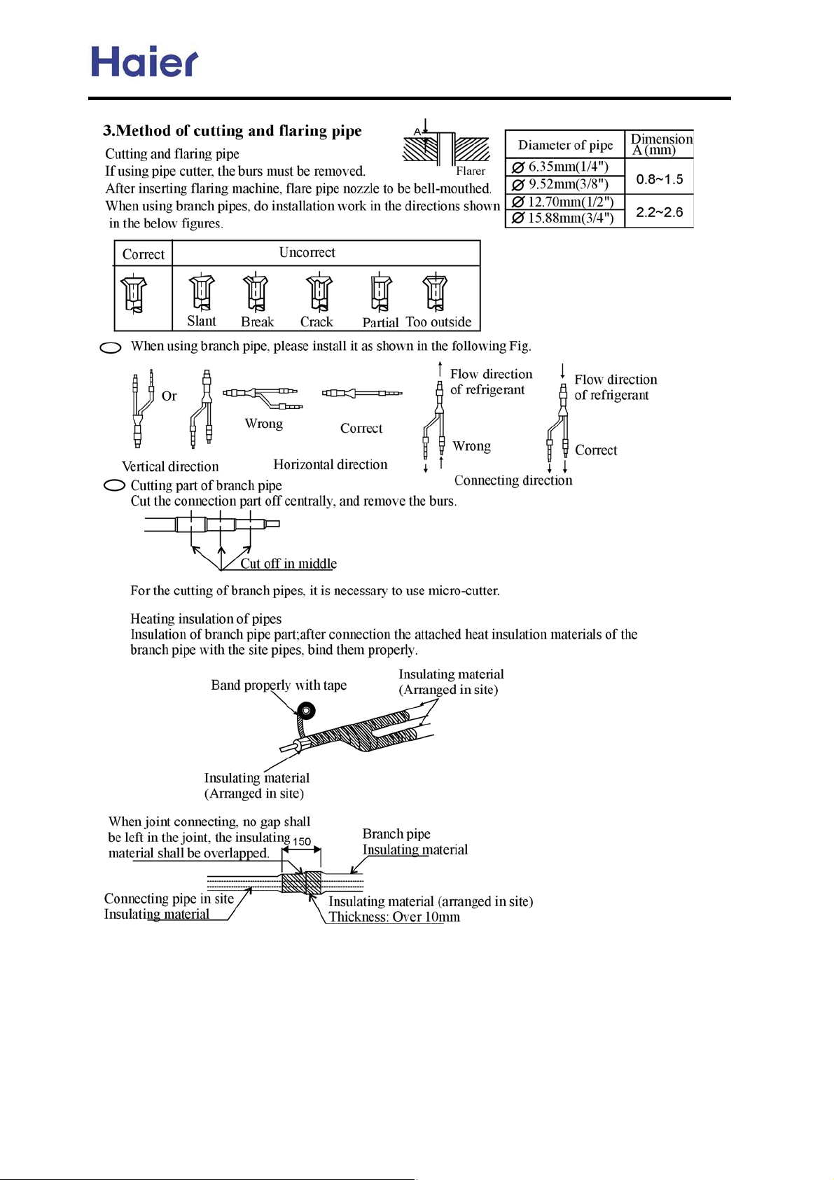
(4) Pipe connection of the outdoor unit
Referring to the installation diagram in page 4, connect the indoor unit, outdoor unit,
branch pipe and electronic expansion valve together by using the pipe connection method and
welding method.
-32-
Page 33
Commercial Air Conditioner Model: AU242FHBIA,
AU482FIBIA, AU48NFIBJA
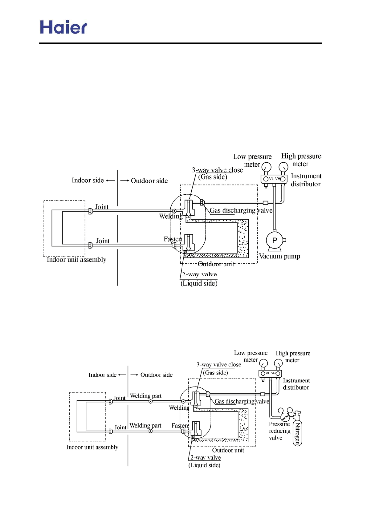
5.9 Test of leakage after wiring work is finished
After connection of the refrigerant pipes, carry out leakage test. In this test,
pressurize to the pipes as shown in the below figure by using nitrogen tank.
Close the valves of the gas side and liquid side totally.
The nitrogen may enter the cycle system of the outdoor unit, so that, before pressurizing, the
valve rods must be fastened. (Both the gas side and liquid side).
For each of the refrigerant system, pressurize from the discharge valve of gas side in
procedure.
When doing leakage test, it is absolutely forbidden to use oxygen, flammable gas and
poisonous gas. The indoor unit expansion valve must be open.
5 vacuuming of the pipes and indoor unit (using vacuum pump to vacuums, it is strictly forbidden to use
refrigerant purging)
a. Choose of vacuum pump: it shall choose those that can reach a good vacuity (over 200Pa)and have
a large air discharge amount (over 40L/min).
b. After finishing the airtight quality test and the nitrogen discharging , connect the instrumental diverter
to the 3-way discharge valve, then connect the vacuum pump according to the below figure.
-33-
Page 34
Commercial Air Conditioner Model: AU242FHBIA,
AU482FIBIA, AU48NFIBJA
c. Vacuumize 2~3 hours according to the length of the pipe. When vacuuming, confirm the
gas side and liquid side of the 2-way valve and 3-way valve shall be in full close state.
d. When it is not lower than 200Pa after 2 hours or more vacuuming, vacuums for another 1
hour. If after more than 3 hours vacuuming it is still not lower than 200Pa, the leak part
shall be found.
e. When it is lower than 200Pa after more than 2 hours vacuuming, close both the valve VL
and VH of the diverter, then close the vacuum pump. Place it there to observe if the
vacuity changes. If it changes, it indicates leakage exists, so the leak part shall be found.
f. After finishing the above vacuuming work, replace the vacuum pump with refrigerant
tank and turn to the refrigerant charging procedure.
5.10 Charging of refrigerant
1. Calculation of additional charging amount of refrigerant
After finishing vacuuming work, replace the vacuum pump with refrigerant tank and turn to
the refrigerant additional charging procedure.
Calculation of additional charging amount of refrigerant
Before the air conditioner leaving factory, the refrigerant-charging amount does not include
the refrigerant in the site pipe part. Calculate the refrigerant amount for the site pipe first, then
do the additional refrigerant charging work.
Refrigerant charging amount when air conditioner leaves factory
R407C:4200g.
Calculation method:
According to the liquid pipe dimension of site pipe and actual length to calculate the
additional refrigerant-charging amount.
Calculation formula:
Site refrigerant charging amount=Length of liquid pipe x additional refrigerant charging
amount/m
For example: additional charging amount
R (kg) = (L1x0.030kg/m)+(L2x0.065kg/m)
L1: Total length of liquid pipe diameter 6.35mm;
L2: Total length of liquid pipe diameter 9.52mm.
2. Charging of refrigerant
Close all valves of outdoor unit, and charge refrigerant from air discharge valve of gas side.
When can not charge the specified amount, firstly, open all the valves, both liquid side and
gas side, of outdoor unit, then switch the valve of gas side to close state a little. Under this
condition, do cooling operation and charge refrigerant from the discharge valve of gas side. At
this time, adjust the valve of the refrigerant tank to make the refrigerant in Gas State when it
is absorbed by system.
When refrigerant leakage making refrigerant lack in system occurs, the intrinsic refrigerant of
the system shall be recovered and recharge it according to specified amount.
3. Opening of the refrigerant pipe
Open all the valves of outdoor unit
-34-
Page 35
Commercial Air Conditioner Model: AU242FHBIA,
AU482FIBIA, AU48NFIBJA
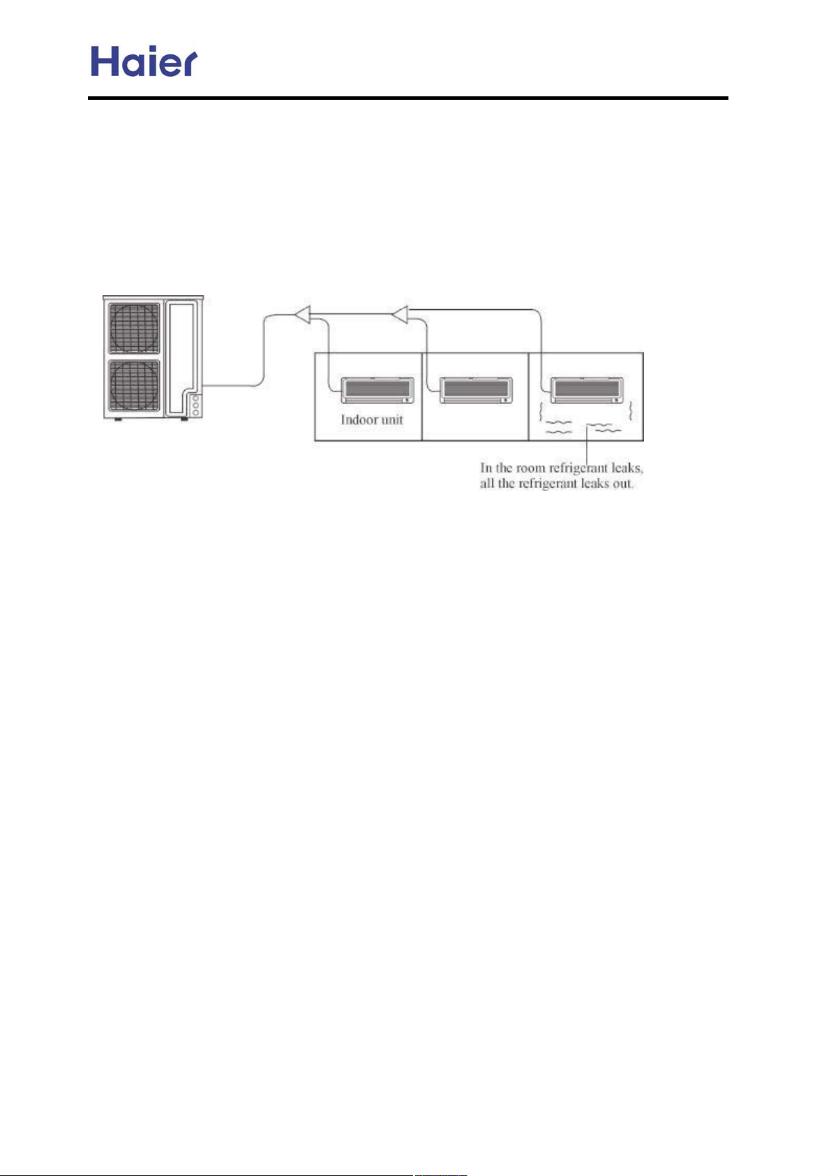
5.11 Refrigerant
QRU Y[cigWa W_g YdcZ_i_dc[gjh[hg[\g_][gWci :RGCIN:A T^_h g[\g_][gWci _ih[a\ _h _ccdYjdjh?cdc@YdbXjhi_Xa[
hW\[in g[\g_][gWciAMji i^[c? l^[c WggWc]_c] i^[W_g YdcZ_i_dc[g [fj_eb[ci? _i _h c[Y[hhWgn id iW`[ hdb[
hi[eh id iW`[ g[YWji_dch W]W
iW`[c _cid WYYdjci id Wkd_Z bW`_c] i^[YdcY[cigWi_dc d\ i^[ g[\g_][gWci cdi [mY[[Z i^[YdcY[cigWi_dc a_b_i
WcZ di^[gg[a[kWci hi[ehAT^[YdcY[cigWi_dc a_b_i _h i^[YdcY[cig
WcZYWciW`[[b[g][cYnhi[eh id ig[Wii^[YdcY[cigWi_dc d\Pg[dcANdcY[cigWi_dc a_b_i d\ RGCINJ CAF`]BbF
hW\[in g[\g_][gWciA
_chi _c YWh[ d\ i^[ _cZddgh g[\g_][gWci a[W`W][A SjY^ Wh?i^[ gddb h_o[ h^Waa X[
Wi_dc i^Wi_hcdi^Wgb\ja id ^jbWc XdZn
DAS[fj[cY[ d\ g[\g_][gWci YdcY[cigWi_dc W\\_gbWcY[
NWaYjaWi[ i^[ g[\g_][gWci YdcY[cigWi_dc WYYdgZ_c] id i^[\daadl_c] h[fj[cY[A
D=NWaYjaWi[ i^[ idiWag[\g_][gWci@Y^Wg]_c]Wbdjci d\ [WY^d\ i^[ g[\g_][gWi_c] hnhi[b <`]=A
p
R[\g_][gWci Y^Wg]_c]Wbdjci d\ djiZddg hnhi[b > LZZ_i_dcWag[\g_][gWci Y^Wg]_c]Wbdjci
KTdiWag[\g_][gWci Y^Wg]_c]Wbdjci d\ i^[ g[\g_][gWi_c][fj_eb[ci <`]=
R[\g_][gWci Y^Wg]_c]Wbdjci d\ djiZddg hnhi[bJ R[\g_][gWci Y^Wg]_c]Wbdjci l^[c W_g YdcZ_i_dc[ga[Wk[h \WYidgnA
p
LZZ_i_dcWag[\g_][gWci Y^Wg]_c]WbdjciJLZZ_i_dcWag[\g_][gWci Y^Wg]_c]Wbdjci WYYdgZ_c] id i^[ h_i[ e_e[
p
a[c]i^ WcZ e_e[Z_Wb[i[gA
E= NWaYjaWi[ i^[ b_c_bjb h_o[ d\ i^[ gddb hj_iWXa[\dg i^[ _cZddg jc_i Whh[bXan <bF=A
NWaYjaWi[ i^[YdcY[cigWi_dc d\ g[\g_][gWciJ
TdiWag[\g_][gWci Y^Wg]_c]Wbdjci d\ g[\g_][gWi_c][fj_eb[ciBi^[ b_c_bjb gddb h_o[ hj_iWXa[\
Whh[bXan <bF=AR[\g_][gWci YdcY[cigWi_dc a_b_iJ CAF`]B bF
EA Ndjci[gb[Whjg[ l^[c [mY[[Z_c] i^[YdcY[cigWi_dc a_b_i
D= S[i Wc [\\[Yi_k[ de[c_c]\dg k[ci_aWi_dc WcZ\g[h^ W_gA
p
Nji Wc _ciW`[ g[he[Yi_k[an dc i^[ jee[g WcZ adl[geWgi d\ i^[Zddg l^_Y^
Wg[Wh Wg[[fj_kWa[ci id CADH; ]gdjcZ_c]Wg[W? dg Yji Wc _ciW`[ _c di^[geWgi d\ i^[ gddbA
E= R[ZjY[ i^[ idiWag[\g_][gWci Y^Wg]_c]Wbdjci d\ i^[ g[\g_][gWi_c][fj_eb[ci
p
S^dgi[ci^[ g[\g_][gWci e_e[ a[c]i^A R[ZjY[ i^[ _chiWaaWi_dc eaWY[ Z_hiWcY[ X[il[[ci^[ djiZddg
jc_i WcZ i^[ _cZddg jc_i id h^dgi[ci^[ g[\g_][gWci e_e[ a[c]i^? hd i^Wig[ZjY[ i^[ idiWag[\g_][gWci
Y^Wg]_c]Wbdjci d\ i^[ g[\g_][gWi_c][fj_eb[ciA
F=OhiWXa_h^ k[ci_aWi_dc WcZ\g[h^ W_g hnhi[b
OhiWXa_h^ W b[Y^Wc_YWa [fj_eb[ci \dg \g[h^ W_g id `[[ei^[ g[\g_][gWci YdcY[cigWi_dc X[adl i^[YdcY[cigWi_dc
p
a_b_i <cdgbWak[ci_aWi_dc=
p
V^[c YWc cdi k[ci_aWi[ i^[ cdgbWaan? ea[Wh[ h[i Wc WaWgb WeeWgWijh a_c`[Z l_i^ i^[ b[Y^Wc_YWa
k[ci_aWi_dc [fj_eb[ciA
8
dg _cZddg jc_i
-35-
Page 36
Commercial Air Conditioner Model: AU242FHBIA,
AU482FIBIA, AU48NFIBJA
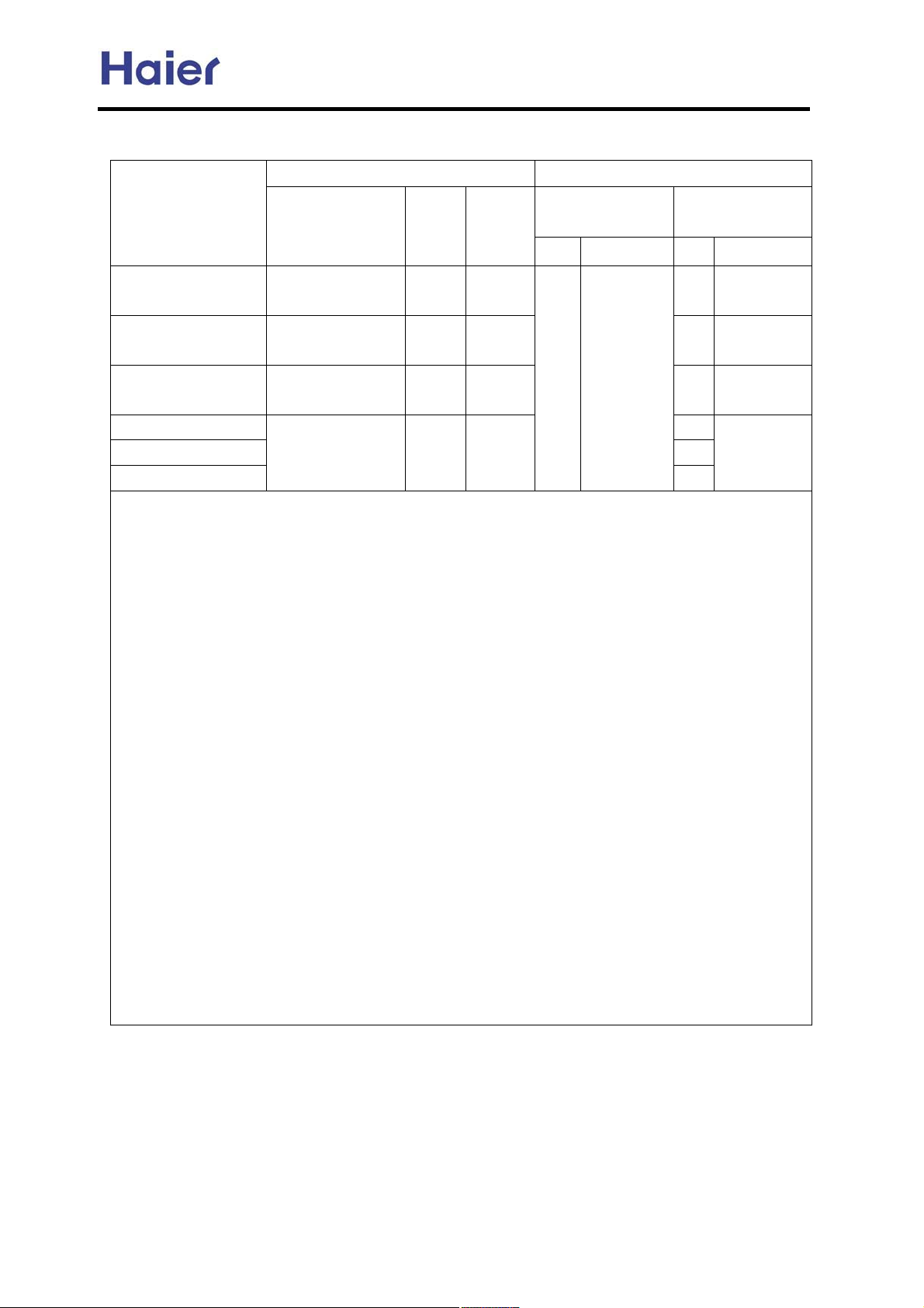
5.12 Electric cautions:
Power supply specs Connecting wire
model
Power source
Circuit
breaker
Power
cable
wire
core section area core section area
Communication
AU242FHBIA
AU482FIBIA
AU48NFIBJA
AE*FCBKA 3
AS*FCBHA 3
1PH, 220-230V~,
50Hz
1PH, 220-230V~,
50Hz
3PH, 380-400V~,
50Hz
1PH, 220-230V~,
50Hz
30A 5mm
50A 10mm
20A 4 mm
15A 1.5mm
2
2
2 1.0-1.5mm
2
2
AB*FCBIA
Remark:
1. Must not connect the power cable and communication wire incorrectly. Forbidden to connect
the power cable and communication wire with one muti-core cable, and they must be wired
separately, keep proper distance between them to ensure the air conditioner run normally.
2. Communication wires among indoor units should be hand in hand type, and decrease the
branch, also the shielded layer should be connected together and be earthed on one point.
3. All indoor communication wires will be connected to the communication bus wire (2-core), C1
and C2 are non-polar.
4. Because the indoor unit adopts EEV control method, when a sudden power off occurs, the
EEV maybe keep some angle. If indoor unit and outdoor unit connect to power supply
separately, when some indoor units running in cooling mode, when powered off, because
the EEV does not reset, the indoor units maybe drop water, or ice up. We recommend that the
indoor unit connect to power supply from the outdoor unit, or use one power supply with the
outdoor unit. If the indoor unit need connect power supply individually, the personnel must
explain to the customer that he (she) must switch off the unit with wired controller or remote
controller, then he (she) can shut off the indoor unit. If there is accidental power failure,
please firstly power on all the indoor units after power on, in order to reset the indoor EEV.
5. When wiring the MP2A or MP3A, please ensure that the power source and the communication
wires of MP2A or MP3A must correspond with the relative indoor units.
6. AS*FCBHA and the cassette unit will not be connected with the MP2A or MP3A.
7. If the ceiling concealed indoor unit is with the electric heater, the circuit breaker will vary
accordingly.
Wired controller
wire
2
0.75mm
3
2
-36-
Page 37
Commercial Air Conditioner Model: AU242FHBIA,
AU482FIBIA, AU48NFIBJA
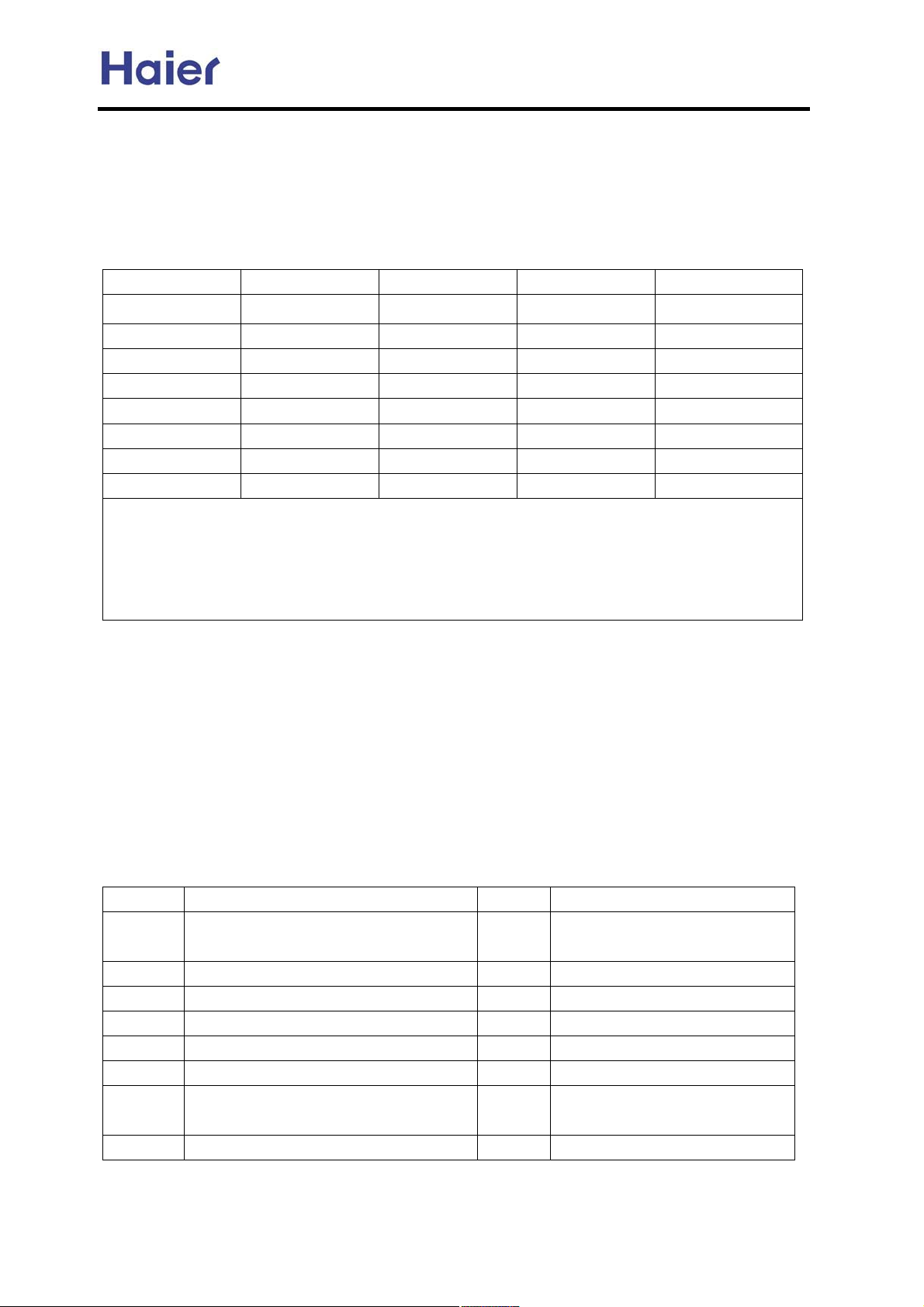
5.13 Indoor unit number setting:
Indoor unit has two kinds of control type: infrared control and wired contrl, so the corresponding
unit address setting will vary as the following: for the infrared control type unit, set with the
address setting controller; for the wired control type unit, set with the dip switch, and the unit
number is from 1 to 8.
(1) Number setting for wired control type unit:
1 2 3 4 Indoor unit No.
0 0 0 0 1
1 0 0 0 2
0 1 0 0 3
1 1 0 0 4
0 0 1 0 5
1 0 1 0 6
0 1 1 0 7
1 1 1 0 8
Note:
1. Dip switch at ON position shows 0.
2. If there are not only the infrared control type unit also the wired control type unit in the whole
system, please set the wired control type unit number firstly and then record the numbers,
then set the infrared control type unit number, to avoid the repeated unit number.
(2) Number setting for infrared control type unit:
Please refer to the manual of address setting controller ASC-02.
5.14 The dip switch setting when out of factory:
AE*FCBKA: Unit No.: 3; 3 fan speeds; wired control type; exterior EEV. That is: SW01-1 ON,
SW01-2 OFF, SW01-3 ON, SW01-4 OFF; SW02-1 ON, SW02-2 OFF; SW03-1 ON, SW03-2 ON.
AB*FCBIA: Unit No.: 3; 3 fan speeds; infrared control type; built-in EEV. That is: SW01-1 ON,
SW01-2 OFF, SW01-3 ON, SW01-4 OFF; SW02-1 OFF, SW02-2 ON; SW03-1 OFF, SW03-2 ON.
When installation, the installer should adjust the setting according to the actual condition.
The ports functions for AB and AE unit (some are optional):
port Corresponding parts port Corresponding parts
CN4 Negative ion generator or high-voltage
accumulator
CN6 EEV CN7 Pump motor
CN10 Indoor motor CN11 Float switch
CN12 Swing motor CN13 Remote receiver
CN14 Wired controller CN18 Neutral line of terminal block
CN19 Auxiliary electric heating CN20 Live line of terminal block
CN22 Auxiliary electric heating CN24
CN25 Communication of EEV box CN9 Pre-set
CN5 Gas/liquid pipe temp. sensor
Room temp. sensor ˄ AE*
unnecessary˅
-37-
Page 38
Commercial Air Conditioner Model: AU242FHBIA,
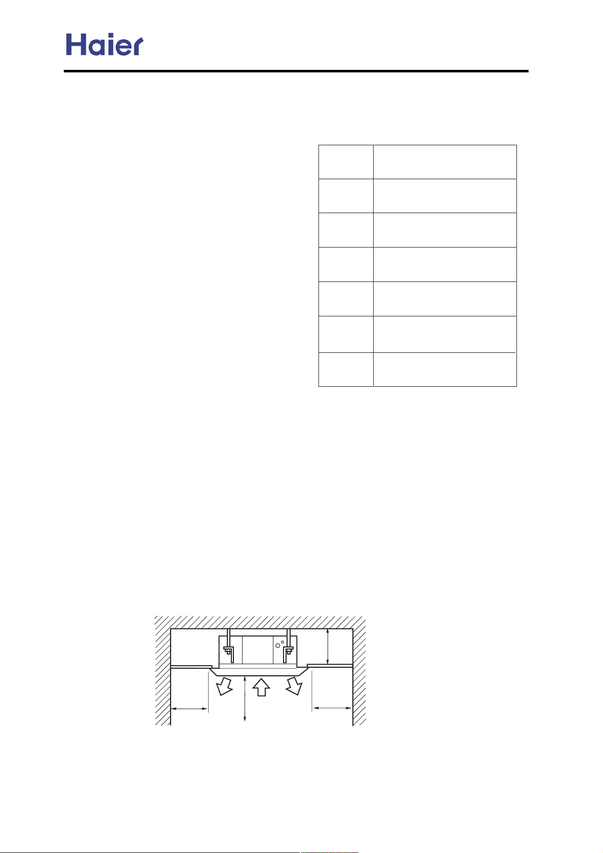
Cassette unit installation:
t~,-w||w-{*~v**|,
HdijWbbWj_ed jeebi
Q^[ _dijWbbWj_ed jeebi b_ij[Z _dj^[ \ebbem_d] i^[[j
YWd X[ ki[Z Wi h[gk_h[Z0
30 PYh[m Zh_l[h
40 GWYaiWm
50 Ch_bb m_j^ WZ_Wc[j[h e\ 82cc
60 Hdd[h ^[nW]ed ifWdd[h.i^_\j_d]
ifWdd[h
70 PfWdd[h ,36. 39. 3;.46.49cc-
80 N_f[ Ykjj[h
90 N_f[ [nfWdZ[h
:0 Id_\[
;0 N_dY[hi
320 J[WaW][ Z[j[Yjeh eh ieWfo mWj[h
330 AWdZ jWf[
340 PYhWf[h
350 O[\h_][hWdj e_b
AU482FIBIA, AU48NFIBJA
Q^[ \ebbem_d] fWhji c[dj_ed[Z _dj^_i cWdkWb
Wh[ j^[ _dijWbbWj_ed WYY[iieh_[i m[ fh[fWh[Z0
PocXeb NWhji LWc[
@
A
B
C
D
E
@Z^[i_l[ jWf[
N_f[ YbWcf
Bedd[Yj_d] ^ei[
ChW_dW][ ^ei[
Led/^oZheiYef_Y
^[Wj _dikbWj_d] cWj[h_Wb
Fofikc femZ[h
t~,-w||w-{*~u+*xzy.+z,
30P[b[Yj_ed e\ HdijWbbWj_ed NbWY[
,3- NbWY[ WXel[ j^[Y[_b_d] m^[h[ _j _i [dek]^ ifWY[ je WhhWd][ j^[kd_j0
,4- NbWY[ m^[h[ j^[ ZhW_dW][ f_f[ YWd X[ WhhWd][Z m[bb0
,5- NbWY[ m^[h[ _db[j WdZ ekjb[j W_he\_dZeeh WdZ ekjZeeh kd_jm_bb dej X[ XbeYa[Z0
,6- Ce dej [nfei[ j^[kd_jjej^[ fbWY[ m_j^^[Wlo e_behce_ijkh[ ,[0]0a_jY^[d WdZ mehai^ef-0
,7- Ce dej i[j j^[kd_j _dj^[ fbWY[ m^[h[ Z[ijhkYj_l[ ]Wi ,ikY^ Wi ikb\kh_YWY_Z ]Wi- eh fkd][dj
]Wi ,j^_dd[h WdZ ]Wieb_d[- YedY[djhWj[i WdZ h[jW_di0
,8- NbWY[ ijhed] [dek]^ je ikffehj j^[kd_j0
,9- Le [nf[di_l[ Whj_Yb[i ikY^
,:- Ddek]^ ifWY[ \eh cW_dj[dWdY[0
,;- NbWY[ ceh[ j^Wd 3c WmWo \hec j[b[l_i_ed WdZ hWZ_ejeWle_ZZ_ijkhX_d] j[b[l_i_ed WdZ hWZ_e0
,32- DWio \eh cW_dj[dWdY[0
Wi j[b[l_i_ed WdZ f_Wde X[bem _dZeeh kd_j0
G
@_h ekjb[j
307c
307c
@_h ekjb[j
407c Ml[h
@_h _db[j
2053c
-38-
Page 39
Commercial Air Conditioner Model: AU242FHBIA,
AU482FIBIA, AU48NFIBJA
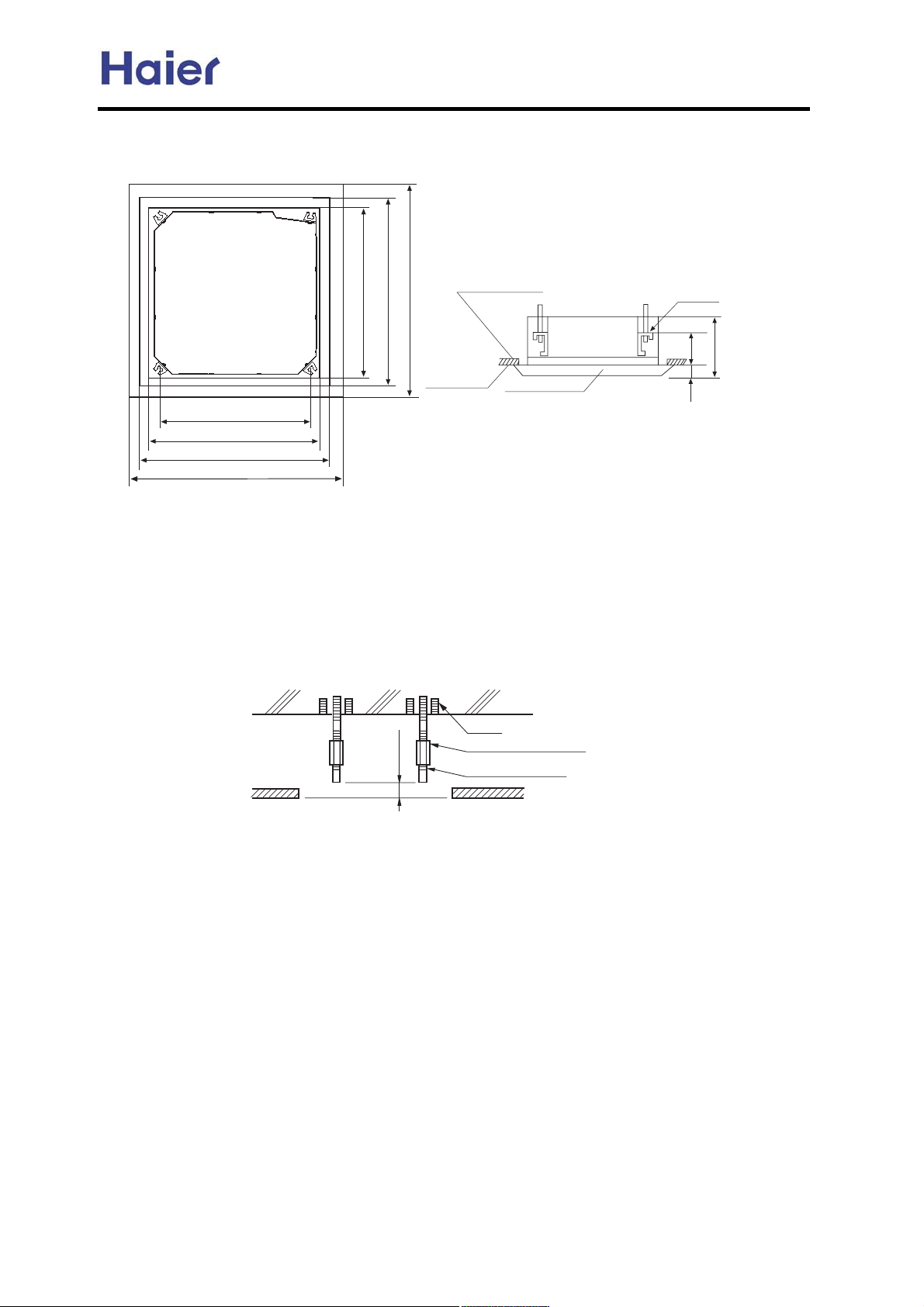
40HdijWbbWj_ed Nh[fWhWj_ed
,3- Nei_j_ed e\ Y[_b_d] ef[d_d] X[jm[[d kd_j WdZ ikif[dZ_d] Xebj ,\hedj l_[m e\ kd_j-0
Ml[hbWf X[jm[[d Y[_b_d] WdZ
ehdWc[dj fWd[b i^Wbb X[ 47cc
HdZeeh kd_j 792cc
B[_b_d] ef[d_d] 872cc
MhdWc[dj fWd[b 922cc
C_ijWdY[ X[jm[[d
ikif[dZ_d] Xebji 757cc
HdZeeh kd_j 792cc
B[_b_d] ef[d_d] 872cc
MhdWc[dj fWd[b 922cc
B[_b_d]
MhdWc[dj fWd[b
,4- Nh[fWh[ Wbb f_f_d] ,h[\h_][hWdj.mWj[h ZhW_dW][ -WdZ m_h[i ,Yedd[Yj_ed m_h[ e\ h[cej[ Yedjhebb[h. _dZeeh
kd_j Yedd[Yj_ed m_h[i- je j^[ _dZeeh kd_j X[\eh[ _dijWbbWj_ed _d ehZ[h je Yedd[Yj _dZeeh kd_j _cc[Z_Wj[bo
W\j[h _dijWbbWj_ed0
Pkif[dZ_d] Xebji
372cc
542cc
82cc
,5- HdijWbb W ikif[dZ_d] Xebj
Qe ikffehj j^[kd_jm[_]^j .WdY^eh Xebj i^ekbZ X[ ki[Z _dj^[ YWi[ e\
j^[[n_ij_d] Y[_b_d]0 Eeh d[m Y[_b_d]. ki[ \bki^/_d jof[ Xebj. Xk_bj/_d
jof[ Xebj eh fWhji fh[jWh[Z _dj^[\_[bZ0
A[\eh[ ]e_d] ed _dijWbb_d]. WZ`kij j^[Z_ijWdY[ je Y[_b_d]0
Oee\
@dY^eh Xebj
Jed] dkj eh j^h[WZ
72 q372cc
Pkif[dZ_d] X_bj K32
B[_b_d]
>HdijWbbWj_ed DnWcfb[?
Lej[< @bb j^[ WXel[ c[dj_ed[Z fWhji i^Wbb X[ fh[fWh[Z _d\[_bZ. j^[Z_Wc[j[h e\ ikif[dZ_d] Xebj _i K32
50 HdijWbbWj_ed e\ _dZeeh kd_j
Hd YWi[ e\ de Y[_b_d]
HdijWbb kd_j j[cfehWh_bo
Nkj ikif[dZ_d] XhWYa[j ed j^[ ikif[dZ_d] Xebj je ^Wd] j^[kd_j kf0 A[ ikh[ je ki[ dkj WdZ mWi^[h Wj
Xej^ [dZ e\ j^[ Xh[Wa[j je i[Ykh[ \_hcbo0
@\j[h _dijWbbWj_ed ed j^[Y[_b_d]
,3- @Z`kij kd_jje_ji h_]^j fei_j_ed ,O[\[h je fh[fWhWj_ed \eh _dijWbbWj_ed/,3-,4-B^[Ya j^Wj kd_j _i ^eh_pedjWb0
TWj[h fkcf WdZ \beWj_d] im_jY^_i _dijWbb[Z _di_Z[ _dZeeh kd_j.Y^[Ya \ekh Yehd[hi e\ j^[kd_j \eh
_ji b[l[h ki_d] ^eh_pedjWb YecfWhWjeh eh NSB jkX[ m_j^ mWj[h0,H\ kd_j _ij_bj_d] W]W_dij j^[Z_h[Yj_ed
e\ mWj[h ZhW_dW][.fheXb[c cWo eYYkh ed \beWj_d] mWj[h b[WaW][0-
-39-
Page 40
Commercial Air Conditioner Model: AU242FHBIA,
AU482FIBIA, AU48NFIBJA
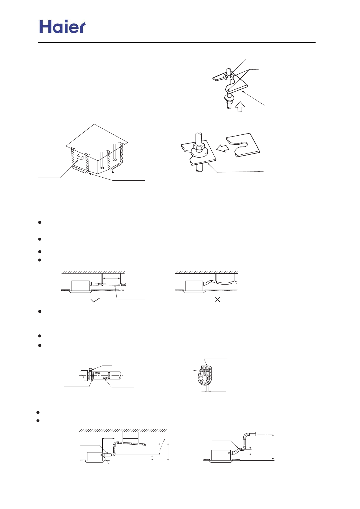
Hd j^[ YWi[ e\ [n_ij_d] Y[_b_d]
,3-HdijWbb kd_j j[cfehWh_bo
Lkj ,Nh[fWh[ _d\[_bZ-
TWi^[h ,Nh[fWh[Z _d\[_bZ-
Nkj ikif[dZ_d] XhWYa[j ed j^[ ikif[dZ_d] Xebj je ^Wd] j^[
kd_j kf0A[ ikh[ je ki[ dkj WdZ mWi^[h Wj Xej^ [dZ e\ j^[
XhWYa[j je i[Ykh[ _j\_hcbo0
,4-@Z`kij j^[ ^[_]^j WdZ fei_j_ed e\ j^[kd_j0
,5-NheY[[Z m_j^ fheY[Zkh[ ,6- e\ + Hd j^[ YWi[ e\ de Y[_b_d] +
EWij[d ,ZekXb[ dkji-
Pkif[dZ_d] Xebji
Hdi[hj
TWi^[h \_n_d] fWZ
b[l[b[h
Neboj^[d[ f_f[
,fh[fWh[Z _d\[_bZ-
U i[Ykh[ j^[ mWi^[h \_hcboV
60 HdijWbbWj_ed e\ mWj[h ZhW_dW][ f_f[
,3- HdijWbb mWj[h ZhW_dW][ f_f[
N_f[ Z_Wc[j[h i^Wbb X[ [gkWb eh bWh][h j^Wd j^Wj e\ Yedd[Yj_d] f_f[ ,N_f[ e\ feboj^[d[= i_p[< 47cc=
M0C0< 54cc -
ChW_df_f[ i^ekbZ X[ i^ehj. m_j^ W ZemdmWhZ ibef[ Wj b[Wij 31322 je fh[l[dj W_h XW] \hec \ehc_d]0
H\ ZemdmWhZ ibef[ e\ ZhW_df_f[ YWddej X[ cWZ[.b_\j_d] f_f[ i^Wbb X[ _dijWbb[Z0
I[[f W Z_ijWdY[ e\ 3/307c X[jm[[d ikif[dZ_d] Xebji. je cWa[ mWj[h ^ei[ ijhW_]^j0
3/307c
ibef[ el[h 31322
Ri[ j^[ ZhW_dW][ ^ei[ WdZ Yb_f fhel_Z[Z m_j^ kd_j0
Hdi[hj mWj[h f_f[ _dje mWj[h fbk] kdj_b _j h[WY^[i j^[m^_
j[ jWf[0
Q_]^j[d j^[Yb_f kdj_b ^[WZ e\ j^[ iYh[m _i b[ii j^Wd 6cc \hec ^ei[0
T_dZ j^[ ZhW_dW][ ^ei[ je j^[Yb_fki_d] i[Wb fWZ \eh ^[Wj _dikbWj_ed0
HdikbWj[ ZhW_dW][ ^ei[ _dj^[ heec0
JWh][ i_p[ i[Wb fWZ
,WYY[iieho-
6cc X[bem
QWf[,m^_j[-
Bb_f
ChW_d]W][ ^ei[
Bb_f
70 BWkj_edi \eh j^[ mWj[h ZhW_dW][ b_\j_d] f_f[
HdijWbbWj_ed ^[_]^j e\ mWj[h ZhW_dW][ b_\j_d] f_f[ i^Wbb X[ b[ii j^Wd 4:2cc
Q^[h[ i^ekbZ X[ W h_]^j Wd]b[ m_j^ kd_j .522cc \hec kd_j0
ChW_dW][ ^ei[
522cc X[bem
TWj[h ZhW_dW][
b_\j_d] f_f[
Bb_f
Pkif[dZ_d] XhWYa[j
3/307c
442cc
11/
4:2cc kdj[h
722cc X[bem
-40-
ChW_dW][ ^ei[
97cc X[bem
722cc X[bem
Page 41
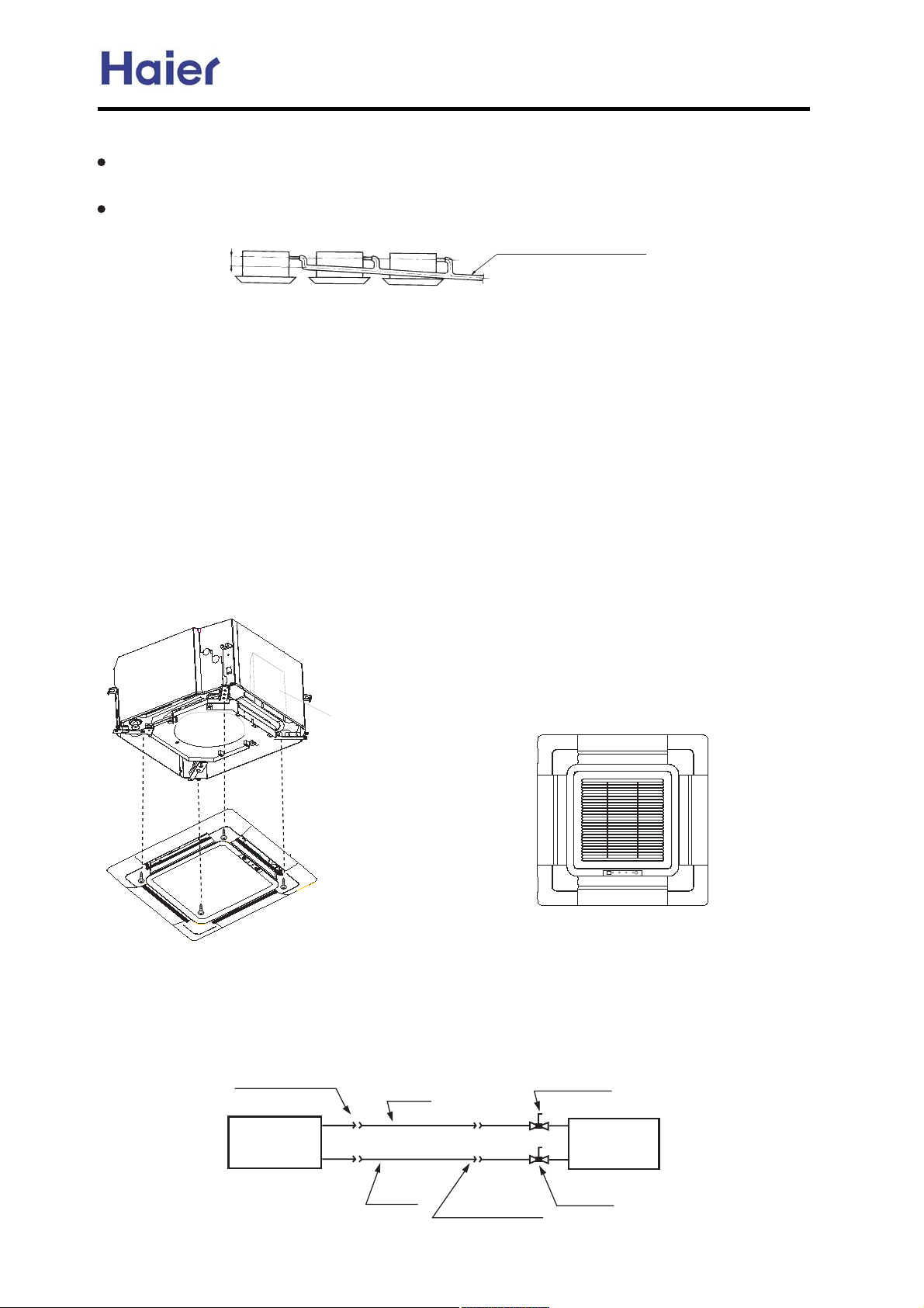
Commercial Air Conditioner Model: AU242FHBIA,
AU482FIBIA, AU48NFIBJA
> Lej[ ?
Q^[ ibef[ e\ mWj[h ZhW_dW][ ^ei[ i^Wbb X[ m_j^_d 97cc . cWa[ j^[ ZhW_dW][ fbk] dej je X[Wh
[nY[ii_l[ \ehY[0
H\ i[l[hWb mWj[h ^ei[i `e_d je][j^[h. e\ Wi f[h \ebbem_d] fheY[Zkh[i0
Pbef[ X[bem 31322
322cc rel[h
Bedd[Yj_ed ZhW_dW][ ^ei[ m_j^ W Q/`e_dj
Pf[Y_\_YWj_edi e\ j^[ i[b[Yj[Z ZhW_dW][ ^ei[i i^Wbb c[[j j^[ h[gk_h[c[dji \eh j^[kd_j hkdd_d]
80 HdijWbbWj_ed e\ MhdWc[dj NWd[b
HdijWbb ehdWc[dj fWd[b ed _dZeeh kd_j
,3- B^[Ya m^[j^[h _dZeeh kd_j _i ^eh_pedjWb m_j^ b[l[b[h eh feboj^[d[ f_f[ \_bb[Z m_j^ mWj[h . WdZ
Y^[Ya j^Wj j^[Z_c[di_ed e\ j^[Y[_b_d] ef[d_d] _i Yehh[Yj0 QWa[ e\\ j^[ b[l[h ]Wk][ X[\eh[
_dijWbb_d] j^[ ehdWc[dj fWd[b0
,4- EWij[d j^[ iYh[mi je cWa[ j^[ ^[_]^jZ_\\[h[dY[ X[jm[[d j^[ jme i_Z[i e\ _dZeeh kd_j b[ii j^Wd
7cc0
,5- E_hijbo \_n _jm_j^ iYh[mi j[cfehWh_
,6- EWij[d j^[ jme j[cfehWh_bo \_n_d] iYh[mi WdZ ej^[h jme. WdZ j_]^j[d j^[ \ekh iYh[mi0
,7- Bedd[Yj j^[m_h[i e\ iodY^he/cejeh0
,8- Bedd[Yj j^[m_h[ e\ i_]dWb0
,9- H\ de h[ifedi[ e\ h[cej[ Yedjhebb[h.Y^[Ya m^[j^[h j^[m_h_d] _i Yehh[Yj.h[ijWhj h[cej[ Yedjhebb[h
32 i[YedZi W\j[h i^kj e\\ fem[h ikffbo0
bo0
Db[Yjh_Y Yedjheb Xen
NWd[b b_c_jWj_ed XeWhZ _dijWbbWj_ed
,3-HdijWbb j^[ fWd[b XeWhZ _dj^[Z_h[Yj_ed i^emd _dj^[\_]kh[0
,4-Q^[ _dYehh[Yj Z_h[Yj_ed m_bb h[ikbj _d mWj[h b[WaW][.c[Wdm^_b[ im_d] WdZ i_]dWb h[Y[_l
j^Wj YWddej X[ Yedd[Yj[Z0
N_f_d] Bedd[Yj_ed
EbWh[ Yedd[Yj_ed
HdZeeh
Rd_j
FWi f_f[
J_gk_Z
f_f[
EbWh[ Yedd[Yj_ed
5/mWo lWbl[
MkjZeeh
kd_j
4/mWo lWbl[
_d] Wh[ Z_ifbWo[Z
-41-
Page 42
Commercial Air Conditioner Model: AU242FHBIA,
AU482FIBIA, AU48NFIBJA
Installation for wall mounted unit
Please read these "Safety Precautions" first then accurately execute the installation work.
The precautionary points indicated herein are divided under two headings:
!
WARNING and CAUTION those points which are related to the strong possibility of an
installation done in error resulting in death or serious injury are listed in the WARNING
section. However, there is also a possibility of serious consequences in relationship to the
points listed in the CAUTION section as well.
In either case, important safety related information is indicated, so by all means, properly
observe all that is mentioned.
After completing the installation, along with confirming that no abnormalities were seen
from the operation tests, please explain operating methods as well as maintenance methods to
the user of this equipment, based on the owner's manual.
Moreover, ask the customer to keep this sheet together with the owner's manual.
Please entrust installation to either the company which sold you the equipment or to a
professional contractor. Defects from improper installations can be the cause of water
leakage electric shocks and fires.
Execute the installation accurately, based on following the installation manual. Again improper
installations can result in water leakage, electric shocks and fires.
Please install your air conditioner on a wall or any place which can holder the weight of the
air conditioner. And it cannot be installed on a non-professional metal structure (such as a
burglary-resisting net). Otherwise injury would occur due to a falling of the unit.
Execute the prescribed installation construction to prepare for earthquakes and the strong airs
of typhoons and hurricanes, etc. Improper installations can result in accidents due to a violent
falling over of the unit.
Wiring shall be done with the specified cable and the connection shall be firm and reliable.
And the terminal connector shall be fixed firmly and reliably not to let external force exercise
on the cables. Any improper connection or fixing would cause heat, fire, and other accidents.
Wiring shall be done in a correct shape not to make any section rise upward, and accurately
install the air conditioner. The cable shall not be clamped by the lid or outer plate. Any
improper installation would lead to fire, heat, or other accidents.
When setting up or moving the location of the air conditioner, do not mix air etc, or anything
other than the designated refrigerant (R407C) within the refrigeration cycle, for such mixing
would result in rupture and injury caused by abnormal high pressure.
Always use accessory parts and authorized parts for installation construction. Using parts not
authorized by this company can result in water leakage, electric shock, fire and refrigerant
leakage.
The drain pipe must not be placed or connected into the sewage tank where harmful gas such
as sulphurous gas and etc would exist, otherwise the harmful gas would enter the room.
During installation, if the refrigerant is leaked, please immediately take measures of
ventilation, otherwise a harmful gas would be generated whenever the refrigerant meets fire.
After installation, please ensure that the refrigerant is not leaked, because the leakage of
refrigerant would produce a harmful gas if it meets fire or heating stoves.
Don't install the air conditioner where a flammable gas would be probably produced,
otherwise in case the flammable gas is leaked and exists around the unit, fire would be
caused.
For the drain pipe, follow the installation manual to insure that it allows proper drainage and
thermally insulate it to prevent condensation. Inadequate plumbing can result in water
leakage and water damage to interior items.
The refrigerant gas pipe and liquid pipe shall all be thermally insulated to preserve the
temperature. Any improper insulation would make the unit moist and the water would drop
onto the floor or wet the indoor items.
!
!
!
WARNING
-42-
Page 43
Commercial Air Conditioner Model: AU242FHBIA,
AU482FIBIA, AU48NFIBJA
PRECAUTION
Execute proper grounding. Do not connect the earth wire to a gas pipe, water pipe,
lightening rod, or a telephone ground wire.
Improper placement of earth wires can result in electric shock.
An electric leakage breaker must be installed, otherwise electric shock or other accidents
would occur.
After completion of the installation, the air conditioner shall be electrified to check for
electric leakage.
Preparation for installation
Installation Tools
1. Screw Driver (flat head, wabbler, triangle)
2. Steel Saw
3. 60mm Drill
4. Inner Hexagon Spanner
5. Shifting Spanner
6. Spanner
7. Pipe Cutter
8. Pipe Expander
9. Knives
10. Clippers
11. Leakage Checker or Soap Liquid
12. Measuring Tape
13. Scraper or File
14. Refrigeration Oil
Self-contained Accessories
No.
Name of
Parts
A
Non-adhesive
Tape
BCDEF
Adhesive
tape
Connecting
Hose
insulation
Gypsum
powder
Drain hoseHeat
material
Electrical Requirements
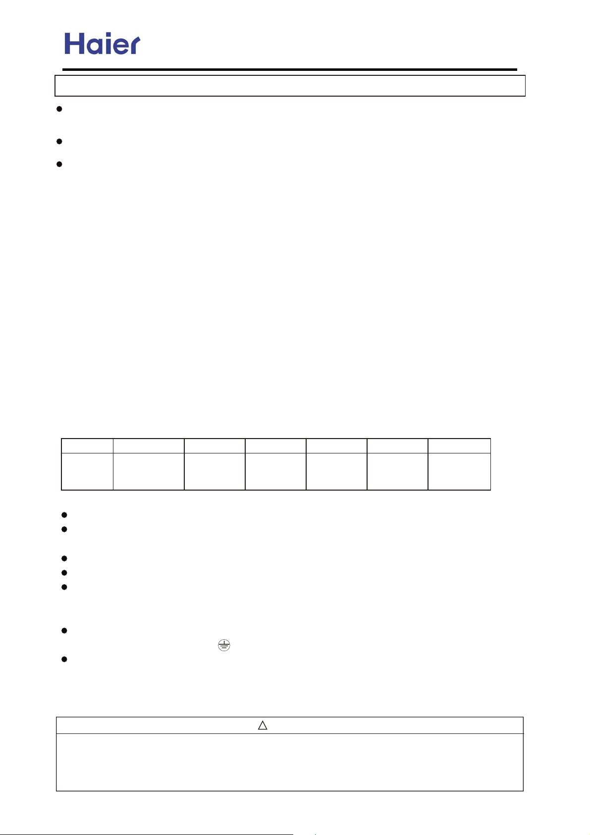
Power supply voltage: Single Phase 1PH, 220-230V~, 50Hz.
A specialized power supply wire, which shall be installed by a competent person as per the
rules of the national standard.
Power supply must be grounded effectively.
An electric leakage breaker shall be installed.
Layout of power supply wiring shall be Y connection. If the power supply wire is damaged, it
must be replaced by the manufacturer or its service center or professional person (the power
supply wire shall be self-contained).
For connection of the power supply plug, L shall be connected with the live wire, N shall be
connected with netural line, shall be connected with earth wire.
Power supply wire parameters:H05RN-F,3 G(1.0-1.5)mm ;
Signal wire parameters:H05RN-F,2 (0.75-1.5)mm . (User shall self-provide signal wire )
X
2
2
Note:The singnal wire and connection wire should be provided for oneself.
The singnal wire must be shielded wire
!
WARNING
BE SURE TO READ THESE INSTRUCTIONS CAREFULLY BEFORE BEGINNING INSTALLATION. FAILURE TO
FOLLOW THESE INSTRUCTIONS COULD CAUSE SERIOUS INJURY OR DEATH, EQUIPMENT MALFUNCTION
AND/OR PROPERTY DAMAGE.
BE SURE TO READ INSTALLATION MANUAL FOR INDOOR UNIT WITH THIS MANUAL.
-43-
Page 44
Commercial Air Conditioner Model: AU242FHBIA,
AU482FIBIA, AU48NFIBJA
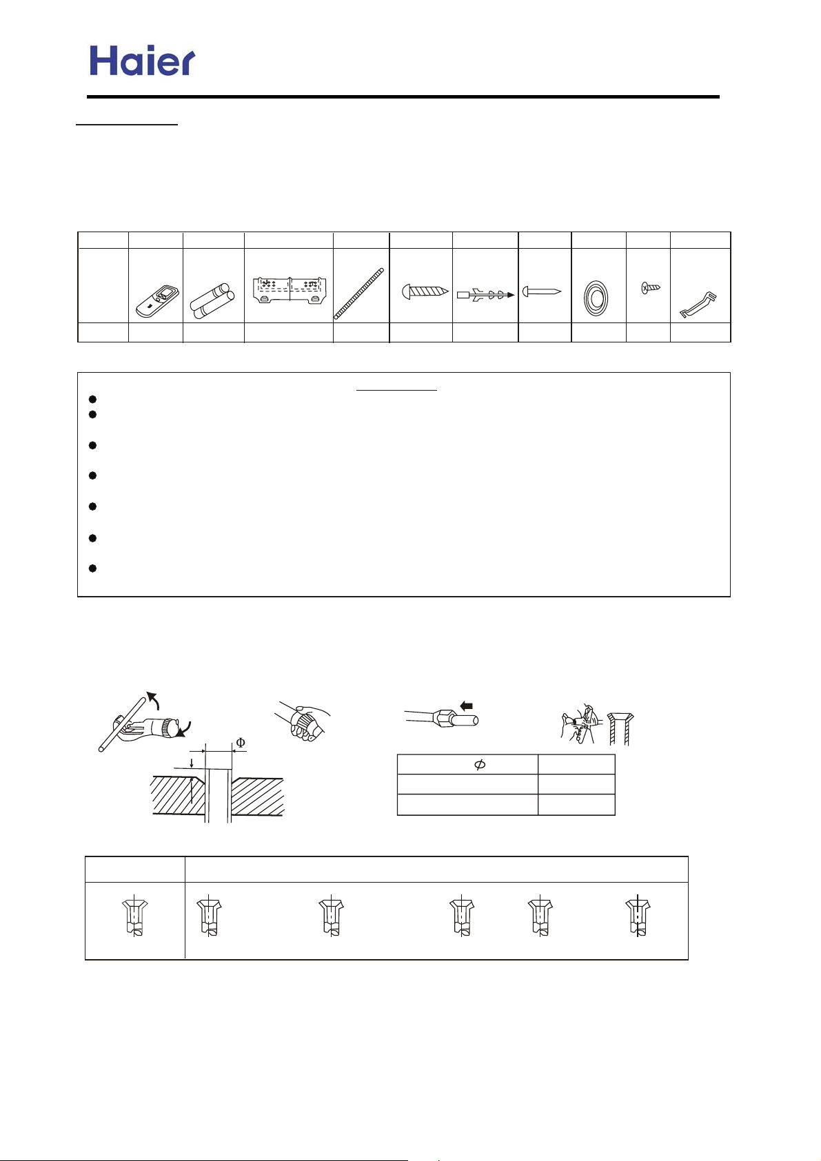
1.Accessories
Confirm accessories shown below are attached in the bag with this Installation manual.
Accessories Delivered with Your Air Conditioner
Please check if your unit is delivered with the following accessories.
No.
Name
12 3 4
Remote
controller
Batteries
Mounting plate
Drain hose
5
x
4 25 screw
6
Expansion
bushing
Cement
steel nail
Piping hole
cover
Screw
and
shape
Qty
1121
66
81 2
Indoor Unit
Install the indoor unit where the weight of the unit can be supported.
Install the indoor unit where the heat source and steam source are not close and the
Unit inlet and outlet are not blocked.
Install the indoor unit where the drainage is easy and the outdoor unit can be
Easily connected.
Install the indoor unit where its cold air and hot air can be easily sent to all the comers
of the room.
Install the indoor unit where the power socket is near and there is sufficient space
around the indoor unit.
Install the indoor unit where there is no T.V set, radio set, and wireless appliance
Underneath, and the sunlight lamp is over one meter away.
If the remote controller is installed on the wall, the indoor unit shall be ensured to receive
The signal while the sunlight lamp is on.
Method for Cutting and Expanding Pipes.
When the pipe is too long or the mouth is damaged, the pipe needs to cut or expanded.
1.cutting hose
2.Removing burr
3.Put on nut 4.Expand Hose
10987
Plastic
supporting
plate
1
Correct
A
Hose Expander
cracks on expanded mouth
Expansion Size
Hose dia.
6.35 mm(1/4)
12.7 mm(1/2)
Not Correct
burr
-44-
Size (mm)A
0.8-1.5
1.0-2.0
incomplete too longTilting
Page 45
Commercial Air Conditioner Model: AU242FHBIA,
AU482FIBIA, AU48NFIBJA
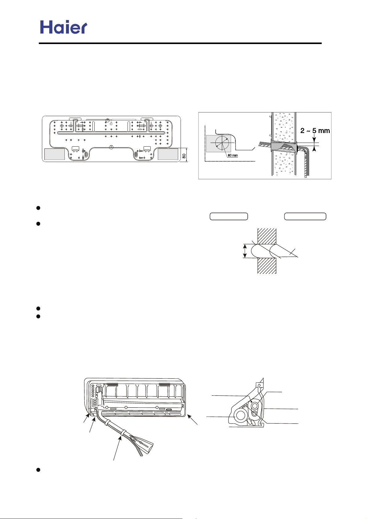
When the mounting plate is firstly fixed
1. Carry out, based on the neighboring pillars or lintels, a proper leveling for the plate
to be fixed against the wall, then temporarily fasten the plate with one steel nail.
2. Make sure once more the proper level of the plate, by hanging a thread with a
weight from the central top of the plate, then fasten securely the plate with the
attachment steel nail.
3. Making a Hole on the wall and Fitting the piping Hole cover
Make a hole of 60mm in diameter,
slightly descending to outside the wall.
Install piping hole cover and seal it
off with putty after installation.
Indoor side
Wall hole
60mm
Outdoor side
Thickness
of wall
4. Drawing of pipe
(Section of wall hole) Piping hole pipe
Rear piping
Draw pipes and the drain hose, then fasten them with the adhesive tape.
Left Left-rear, piping
In case of left side piping, cut away, with a nipper, the lid for left piping.
In case of left-rear piping, bend the pipes according to the piping direction to the mark
of hole for left-rear piping which is marked on heat insulation materials.
a. Insert the drain hose into the dent of heat insulation materials of indoor unit.
b. Insert the indoor/outdoor electric cord from backside of indoor unit, and pull it out
on the front side, then connect them.
c. Coat the flaring seal face with refrigerant oil and connect pipes.
Cover the connection part with heat insulation materials closely, and make sure fixing
with adhesive tape.
Lid for right piping
Lid for under piping pipe
Heat insulation
material
Drain hose
Lid for left piping
Piping
Pipe supporting
plate
Indoor/Outdoor
Electric cable
Fix with adhesive tape
Indoor/outdoor electric cord and drain hose must be bound with refrigerant piping by
Protecting tape.
-45-
Page 46
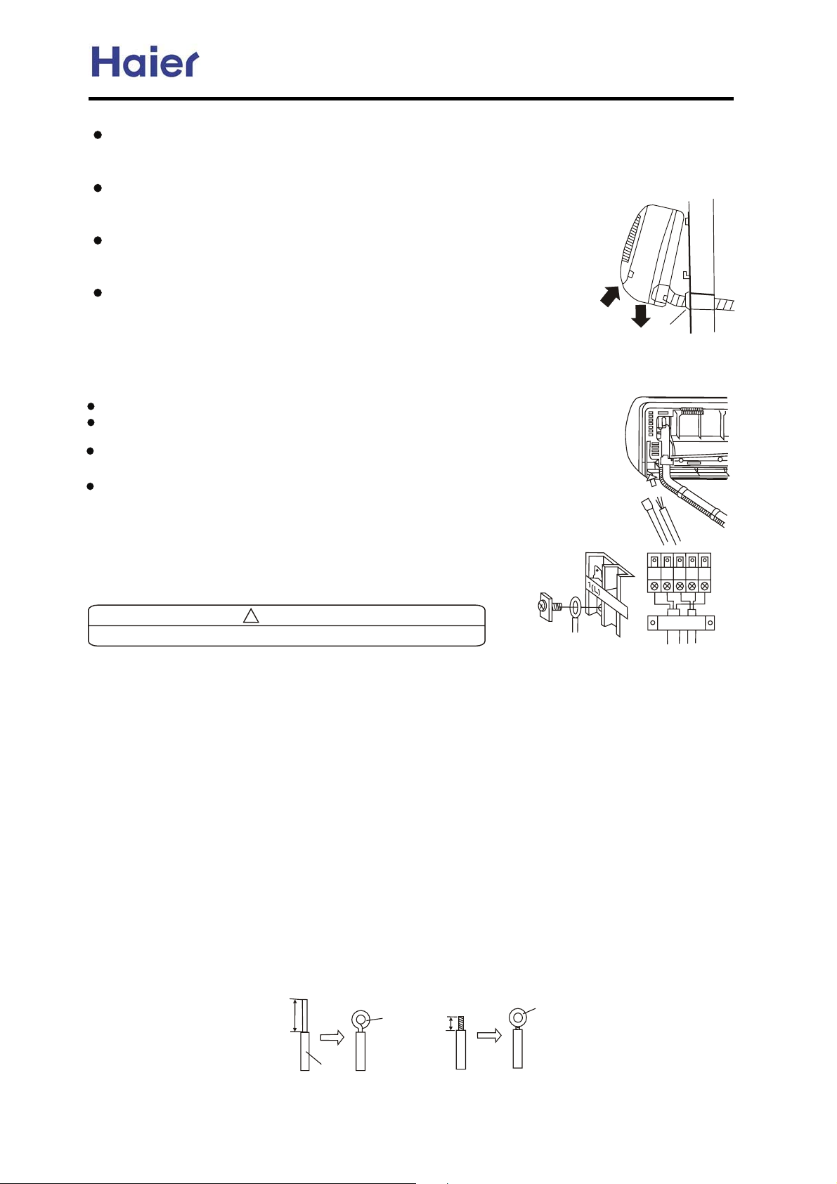
Commercial Air Conditioner Model: AU242FHBIA,
AU482FIBIA, AU48NFIBJA
Other direction piping
Cut away, with a nipper, the lid for piping according to the piping direction and then
bend the pipe according to the position of wall hole. When bending, be careful not
to crash pipes.
Connect beforehand the indoor/outdoor electric cable, and then pull out the
connected to the heat insulation of connecting part specially.
5.Fixing the indoor unit body
Hang surely the unit body onto the upper notches of the
mounting plate. Move the body from side to verify its
secure fixing.
In order to fix the body onto the mounting plate, hold up
the body aslant from the underside and then put it down
perpendicularly.
Putty
Electric wiring
When connecting the cord before installing the indoor unit
Insert the cord from the back side of the unit, then pull it out on the front side.
Loosen the screws and insert the cord ends fully into terminal block, then
tighten the screws.
Pull the cord slightly to make sure the cords have been properly inserted and
tightened.
After the cord connection, never fail to fasten the connected cord with the
wiring cover.
Note: when connecting the cord, confirm the
terminal number of indoor and outdoor units
carefully. If wiring is not correct, proper operation
can not be carried out and will cause defect.
!
CAUTION
After connecting the p iping, check the joints for gas leakage with gas leakage detector.
HOW TO CONNECT WIRING TO THE TERMINALS
A. For solid core wiring (or F-cable)(Fig.17A)
(1) Cut the wire with a wire cutter or wire-cutting pliers, then strip the insulation to about 25mm of
the exposed solid wire.
(2) Using a screwdriver, remove the terminal screw (s) on the terminal board.
(3) Using pliers, bend the solid wire to form a loop suitable for the terminal screw.
(4) Shape the loop wire properly, place it on the terminal board and tighten securely with the terminal
screw using a screw driver.
B. For strand wiring (Fig.17B)
(1) Cut the wire with a wire cutter or wire-cutting pliers, then strip the insulation to about 10mm of
the exposed strand wiring.
(2) Using a screwdriver, remove the terminal screw (s) on the terminal board.
(3) Using a round terminal fastener or pliers, securely clamp a round terminal to each stripped wire end.
(4) Position the round terminal wire, and replace and tighten the terminal screw using a screw driver.
Fig. 17
A. Solid
Loop
B. Strand wire
Round
terminal
Strip 25mm
Insulation
After passing the connection cord and power cable through the
insulation tube, fasten it with the cord clamp, as shown in Fig.18
Strip 10mm
-46-
Page 47
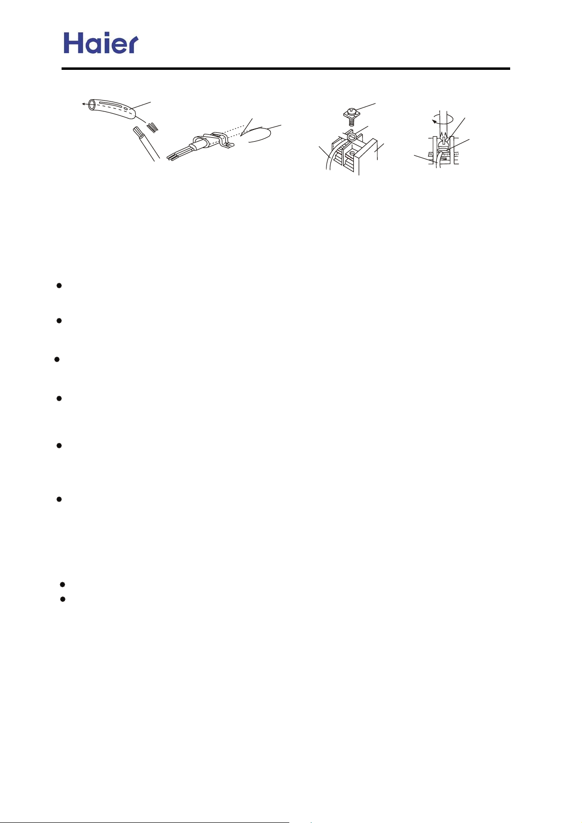
Commercial Air Conditioner Model: AU242FHBIA,
AU482FIBIA, AU48NFIBJA
Fig. 18
Screw with
Insulation tube
Cord clamp
Wire
Use VW-1, 0.5 to 1.0 mm thick, PVC tube as the insulation tube.
special washer
Round
terminal
Terminal
board
Wire
Screw with
special washer
Round
terminal
Check the Layout of the Drain Pipe and Connection Wires
The drain pipe should be placed underneath, and the connection wires should be placed upside;
and the drain pipe especially the section inside the machine and indoors must be wound up with
insulating material to preserve heat. The drain pipe shall be sloped and no concave and convex
shall occur along the whole pipe. And the cases as the right figure indicates shall not occur.
Installation check
Is power supply voltage required?
Is water completely drained to outdoors?
Are power wire and connection wires between indoor and outdoor units correctly connected?
Is any gas leaked from the pipe connectors?
Are series numbers of the terminals on the indoor and outdoor units corresponding to each
other? Is the connection section of the auxiliary pipe insulated? Is the indoor unit fixed firmly?
Is noise big?
Trial Operation
The person who has completed this installation shall be requested to conduct a test operation
for check:
Is the temperature adjuster working normally?
Does the location for installation conform to requirements?
Winding up with Protective Plastic Tape
The connection pipes, drain pipe, and the connection wires shall be wound up with PVC tape.
Notes: The connection pipes shall also be wound up with insulating material to preserve the
temperature. The airing direction shall be from bottom to top.
-47-
Page 48
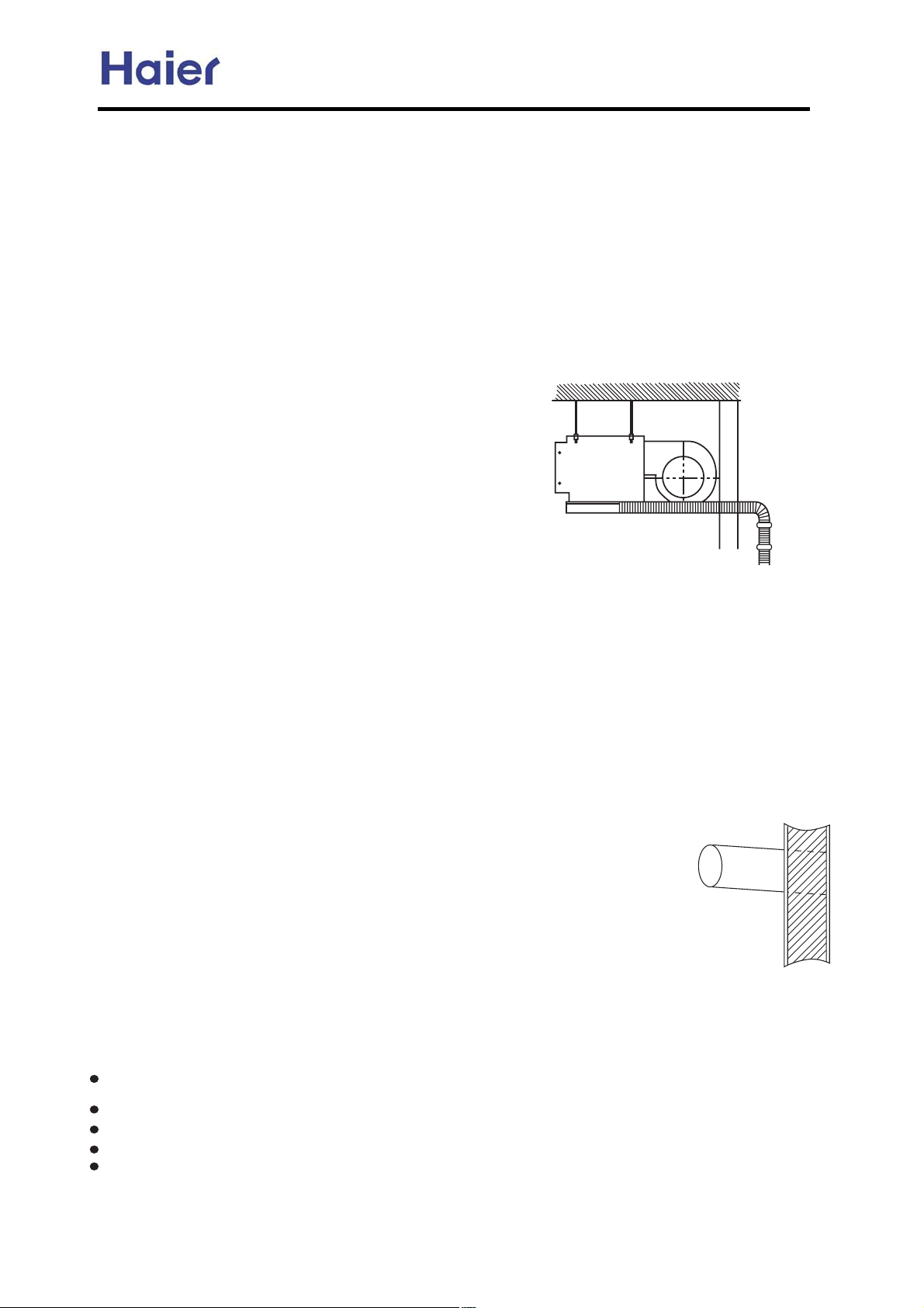
Commercial Air Conditioner Model: AU242FHBIA,
AU482FIBIA, AU48NFIBJA
Ceiling concealed OIEN
6IMN=GG=NEJI MK=?A
S_\ `e[ffi le`k j_Xcc Y\ `ejkXcc\[ XkcfZXk`fej n_\i\Zfc[Xe[ _fk X`i Zflc[\m\ecp Z`iZlcXk\[4
S_\]fccfn`e^ cfZXk`fej j_flc[Y\Xmf`[\[@
OcXZ\j n`k_ i`Z_ jXck /j\Xj`[\ Xi\X04
OcXZ\j n`k_ gc\ekp f] ^Xj jlc]`[\j /dX`ecp `e nXid jgi`e^ Xi\Xj n_\i\ k_\ Zfgg\i klY\ Xe[ YiXq\ n\c[
`j \Xjp kf Zfiifj`fe04
KfZXk`fej n`k_ dlZ_ f`c /`eZcl[`e^ d\Z_Xe`ZXc f`c0 Xe[ jk\Xd4
KfZXk`fej lj`e^ fi^Xe`Z jfcm\ekj4
OcXZ\j n_\i\ k_\i\ Xi\ dXZ_`e\j ^\e\iXk`e^ HF \c\ZkifdX^e\k`Z nXm\j4
Ofj`k`fej X[aXZ\ek kf [ffi fi n`e[fn `e ZfekXZk n`k_ _`^_3_ld`[`kp \ok\ieXc X`i4 /EXjp kf ^\e\iXk\ [\n04
KfZXk`fej ]i\hl\ekcp lj`e^ jg\Z`Xc X\ifjfcj4
9DA BJGGJPEIC KJEINM MDJOG@ >A N=FAI ?=LA JB0
74 R\c\Zk jl`kXYc\ gcXZ\j k_\ flkc\k X`i ZXe Y\ j\ek kf k_\
\ek`i\ iffd2 Xe[ Zfem\e`\ek kf cXp flk k_\ Zfee\Zk`fe
g`g\2 Zfee\Zk`fe n`i\ Xe[ k_\ [iX`eX^\ g`g\ kf flk[ffi4
84 S_\ Z\`c`e^ jkilZkli\ dljk Y\ jkife^ \efl^_ kf jlggfik
k_\ le`k n\`^_k4
94 S_\ Zfee\Zk`e^ g`g\2 [iX`e g`g\ Xe[ Zfee\Zk`fe n`i\
j_Xcc Y\ XYc\ kf ^f k_fl^_ k_\ Yl`c[`e^ nXcc kf Zfee\Zk
Y\kn\\e k_\ `e[ffi Xe[ flk[ffi le`kj4
:4 S_\ Zfee\Zk`e^ g`g\ Y\kn\\e k_\ `e[ffi Xe[ flk[ffi le`kj Xj n\cc Xj k_\ [iX`e g`g\ j_Xcc Y\ Xj j_fik
Xj gfjj`Yc\4 /R\\ F`^li\ 70
;4 I] `kj e\Z\jjXip kf X[aljk k_\ ]`cc`e^ Xdflek f] k_\ i\]i`^\iXek2 gc\Xj\ i\]\i kf k_\ `ejkXccXk`fe dXelXc
XkkXZ_\[ n`k_ k_\ flk[ffi le`k4
<4 S_\ Zfee\Zk`e^ ]cXe^\ j_flc[ Y\ gifm`[\[ Yp k_\ lj\i _`dj\c]4
=4 S_\ `e[ffi le`k _Xj knf nXk\i flkc\kj fe\ f] n_`Z_ `j fYjkilZk\[ Xk k_\ ]XZkfip /n`k_ X ilYY\i ZXg04 Necp
k_\ flkc\k efk fYjkilZk\[ /c`hl`[ `ec\k Xe[ flkc\k j`[\0 n`cc Y\ ^\e\iXccp lj\[ [li`e^ `ejkXccXk`fe4 I]
Xggc`ZXYc\2 Yfk_ k_\ flkc\kj j_flc[ Y\ lj\[ kf^\k_\i4
F`^ 7
Mfk\@ S_\ XZZ\jj _fc\ dljk Y\ gifm`[\[ [li`e^ `ejkXccXk`fe f] `e[ffi le`k ]fi dX`ek\eXeZ\4
1BNAL MAGA?NEIC NDA EIMN=GG=NEJI MK=?A{ KLJ?AA@ NDA BJGGJPEIC MNAKM0
74 Di`cc X _fc\ `e k_\ nXcc Xe[ `ej\ik k_\ Zfee\Zk`e^ g`g\ Xe[ n`i\ k_ifl^_ X OUC nXcc3
k_ifl^_ klY\ gliZ_Xj\[ cfZXccp4 S_\ nXcc _fc\ j_Xcc Y\ n`k_ X flknXi[ [fne jcfg\ f] Xk
c\Xjk 757664 /R\\ F`^li\ 80
84 B\]fi\ [i`cc`e^ Z_\Zb k_Xk k_\i\ `j ef g`g\ fi i\`e]fiZ`e^ YXi aljk Y\_`e[ k_\ [i`cc`e^
gfj`k`fe4 Di`cc`e^ j_Xcc Xmf`[ Xk gfj`k`fej n`k_ \c\Zki`Z n`i\ fi g`g\4
94 Lflek k_\ le`k fe X jkife^ Xe[ _fi`qfekXc Yl`c[`e^ iff]4 I] k_\ YXj\ `j efk ]`id2 `k n`cc
ZXlj\ ef`j\2 m`YiXk`fe fi c\XbX^\4
:4 Rlggfik k_\ le`k ]`idcp4
;4 C_Xe^\ k_\ ]fid f] k_\ Zfee\Zk`fe g`g\2 Zfee\Zk`fe n`i\ Xe[ [iX`e g`g\ jf k_Xk k_\p
ZXe ^f k_ifl^_ k_\ nXcc _fc\ \Xj`cp4
EXZ_ f] k_\ X`i j\e[`e^ [lZk Xe[ X`i i\klie [lZk j_Xcc Y\ ]`o\[ fe k_\ gi\]XYi`ZXk\[ gXe\c f] k_\ ]cffi
Yp k_\ `ife YiXZb\k4
S_\ i\Zfdd\e[\[ [`jkXeZ\ Y\kn\\e k_\ \[^\ f] k_\ X`i i\klie [lZk Xe[ k_\ nXcc `j fm\i 7;6dd4
S_\ ^iX[`\ek f] k_\ Zfe[\ejXk\ nXk\i g`g\ j_Xcc b\\g fm\i 7.4
S_\ Zfe[\ejXk\ nXk\i g`g\ j_Xcc Y\ k_\idXc `ejlcXk\[4
V_\e `ejkXcc`e^ k_\ Z\`c`e^ CfeZ\Xc\[ kpg\ `e[ffi le`k2 k_\ X`i i\klie [lZk dljk Y\ [\j`^e\[ Xe[
`ejkXcc\[ /Xj ]`^li\ j_fne04
F`^ 8
-48-
Page 49
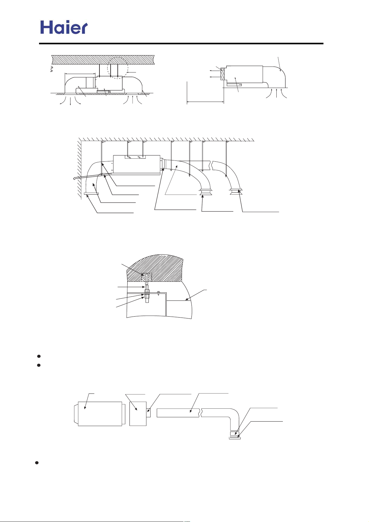
Commercial Air Conditioner Model: AU242FHBIA,
AU482FIBIA, AU48NFIBJA
Bl`c[`e^ iff] f] `ejkXccXk`fe
746d /lj\ n_`k\ dfkfi gcl^0
;46d/lj\ i\[ dfkfi gcl^0
Z\`c`e^
X`i jlggcp
le`k
+
X`i i\klie
X`i i\klie Yfo
A`i flkc\k ^i`cc\
A`i jlggcp
S_\i\ j_flc[ Y\
ef fYjkXZc\j
n`k_`e 7d
X`i i\klie Yfo
le`k
X`i i\klie
Mfk\@ V_\e Zfee\Zk`e^ k_\ j_fik [lZkj2 lj\ k_\ cfn jkXk`Z k\id`eXcj2 n_`Z_ Zfcfi `j n_`k\4
S_\ [`jkXeZ\ K ]ifd k_\ X`i flkc\k f] k_\ [lZk kf k_\ X`i flkc\k f] k_\ j`i Zfe[`k`fe\i j_Xcc Y\ ef dfi\ k_Xe 7 d4
Rljg\e[`e^ _ffb
DiX`e g`g\
A`i i\klie [lZk
A`i i\klie Yc`e[
A`i flk [lZk
SiXej`k`fe [lZk
A`i [`jki`YlkXip
S`\3`e f] X`i
[`jki`YlkXip
S_\ jb\kZ_ dXg f] cfe^ [lZk
Mfk\@ V_\e Zfee\Zk`e^ k_\ cfe^ [lZkj2 lj\ k_\ d`[[c\ jkXk`Z k\id`eXcj2 n_`Z_ Zfcfi `j i\[4
S_\ [`jkXeZ\ K ]ifd k_\ X`i flkc\k f] k_\ [lZk kf k_\ X`i flkc\k f] k_\ j`i Zfe[`k`fe\i j_Xc Y\ ef dfi\ k_Xe ; d4
L> n`[\ \ogXej`fe Yfck
L> jljg\e[\i jZi\n
L> n`[\ cfZb nXj_\i
L> jZi\n elk
A`i Zfe[`k`fe\i
IejkXccXk`fe f] `e[ffi le`k [lZk
74 IejkXccXk`fe f] X`i j\e[`e^ [lZk
S_`j le`k lj\j ifle[\[ [lZk2 k_\ [`Xd\k\i f] k_\ [lZk `j 7>6dd4
S_\ ifle[ [lZk e\\[j kf X[[ X kiXej`k`fe [lZk kf Zfee\Zk n`k_ k_\ X`i3j\e[`e^ [lZk f] `e[ffi
le`k2k_\e Zfee\Zk n`k_ i\jg\Zk`m\ j\gXiXkfi4 Aj F`^4 7 j_fne2 Xcc k_\ ]Xe jg\\[ f] Xep f] k_\ j\gXiXkfiuj
X`i flkc\k j_Xcc Y\ X[aljk\[ Xggifo`dXk\cp k_\ jXd\ kf d\\k k_\ i\hl`i\d\ek ]fi k_\ iffd X`i Zfe[`k`fe\i4
Ie[ffi le`k
]c\o`Yc\ af`ek
SiXej`k`fe [lZk
Qfle[\[ [lZk
S`\3`e f] X`i
[`jki`YlkXip
A`i [`jki`YlkXip
F`^4 7
Te`k@ dd
84 IejkXccXk`fe f] X`i i\klie [lZk
Tj\ i`m\k kf Zfee\Zk k_\ X`i i\klie [lZk fe k_\ X`i i\klie `ec\k f] k_\ `e[ffi le`k2 k_\e Zfee\Zk k_\ fk_\i \e[
n`k_ k_\ X`i i\klie Yc`e[4 Aj F`^4 8 j_fne4
-49-
Page 50
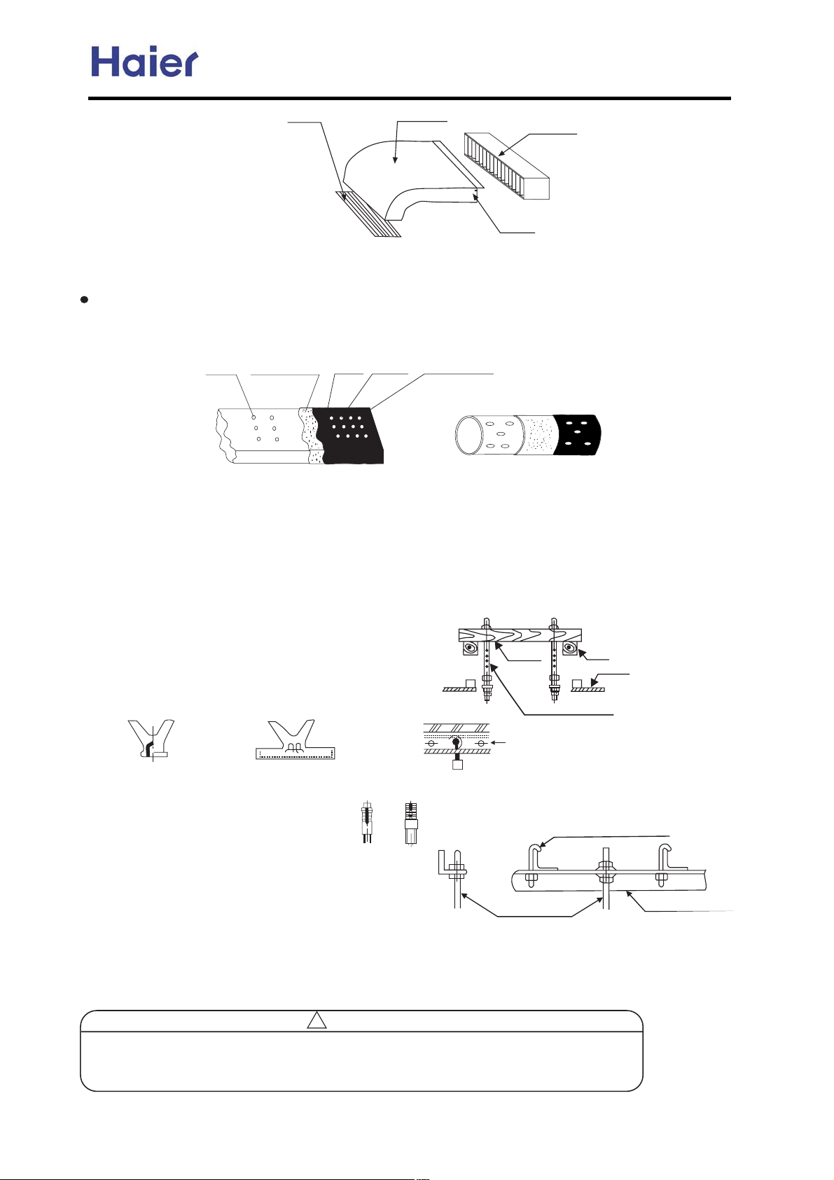
Commercial Air Conditioner Model: AU242FHBIA,
AU482FIBIA, AU48NFIBJA
A`i i\klie Yc`e[
F`^4 8
A`i i\klie [lZk
Ie[ffi le`k
i`m\k
9 S_\idXc `ejlcXk`fe f] [lZk
A`i3j\e[`e^ [lZk Xe[ X`i i\klie [lZk j_Xcc Y\ k_\idXccp `ejlcXk\[4 F`ijk jk`Zb k_\ ^cl\p eX`c fe k_\ [lZk2 k_\e
XkkXZ_ k_\ _\Xk gi\j\imXk`fe Zfkkfe n`k_ X cXp\i f] k`e]f`c gXg\i Xe[ lj\ k_\ ^cl\p eX`c ZXg kf ]`o4 F`eXccp lj\
k_\ k`e]f`c X[_\j`m\ kXg\ kf j\Xc k_\ Zfee\Zk\[ gXik4 Aj F`^4 9 j_fne4
^cl\p
eX`c
_\Xk gi\j\imXk`fe
Zfkkfe
k`e]f`c
^cl\p
eX`c ZXg
X[_\j`m\ kXg\
F`^4 9
IejkXcc`e^ k_\ jljg\ej`fe jZi\n@
Tj\ L> fi L76 jljg\ej`fe jZi\nj /:2gi\gXi\[ `e k_\ ]`\c[0/n_\e k_\ jljg\ej`fe jZi\n_\`^_k \oZ\\[j 64?d2
L76 j`q\ `j k_\ fecp Z_f`Z\04S_\j\ jZi\nj j_Xcc Y\ `ejkXcc\[ Xj ]fccfnj n`k_ jgXZ\ X[Xgk`e^ kf X`i Zfe[`k`fe\i
fm\iXcc [`d\ej`fej XZZfi[`e^ kf k_\ fi`^`eXc Yl`c[`e^ jkilZkli\j4
Vff[\e jkilZkli\
A jhlXi\ nff[ j_Xcc Y\ jlggfik\[ Yp k_\ Y\Xdj Xe[ k_\e j\k k_\ jljg\ej`fe jZi\nj4
RhlXi\ nff[
B\Xd
M\n ZfeZi\k\ jcXY
Sf j\k n`k_ \dY\[[\[ gXikj2]fle[Xk`fe Yfckj \kZ4
Rljg\ej`fe jZi\n
Iife i\`e]fiZ\d\ek
Ffle[Xk`fe Yfck
Je`]\ \dY\[[\[ gXik
Gl`[\ gcXk\ \dY\[[\[ gXik
O`g\ jljg\ej`fe ]fle[Xk`fe Yfck
Ni`^`eXc ZfeZi\k\ jcX[
Tj\ _fc\ _`e^\2_fc\ gcle^\i fi _fc\ Yfck4
HXe^`e^ Yfck
Rk\\c i\`e]fiZ\d\ek jkilZkli\
Tj\ jk\\c Xe^c\ fi e\n jlggfik jk\\c Xe^c\ [`i\Zkcp4
Rljg\ej`fe jZi\n
Rlggfik jk\\c Xe^c\
HXe^`e^ f] k_\ `e[ffi le`k
FXjk\e k_\ elk fe k_\ jljg\ej`fe jZi\n Xe[ k_\e _Xe^ k_\ jljg\ej`fe jZi\n `e k_\ S jcfk f] k_\ jljg\ej`fe
gXik f] k_\ le`k4 A`[\[ n`k_ X c\m\c d\k\i2X[aljk c\m\c f] k_\ le`k n`k_`e ;dd4
w 3=ONEJI
Ie fi[\i kf [iX`e nXk\i efidXccp2 k_\ [iX`e g`g\ j_Xcc Y\ gifZ\jj\[ Xj jg\Z`]`\[ `e k_\
`ejkXccXk`fe dXelXc Xe[ j_Xcc Y\ _\Xk `ejlcXk\[ kf Xmf`[ [\n ^\e\iXk`fe4 Idgifg\i _fj\
Zfee\Zk`fe dXp ZXlj\ `e[ffi nXk\i c\XbX^\4
-50-
Page 51
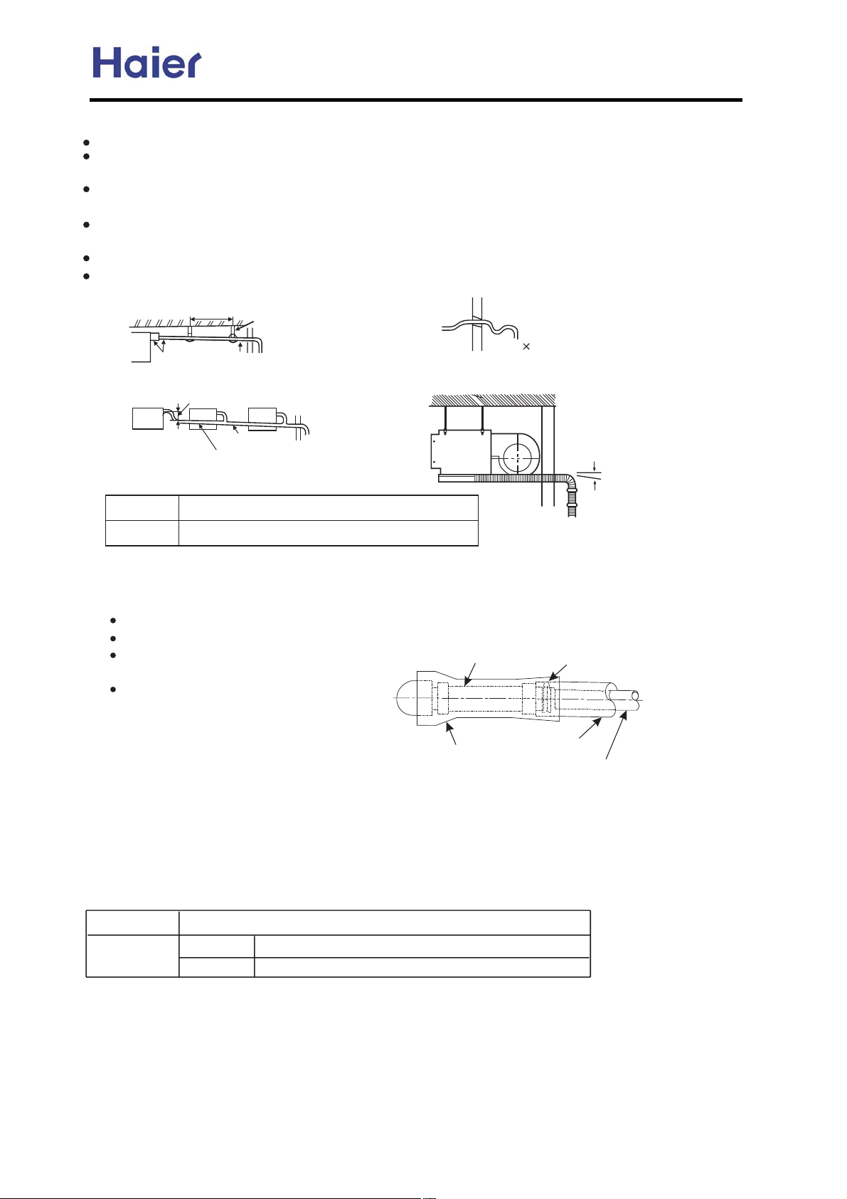
Commercial Air Conditioner Model: AU242FHBIA,
AU482FIBIA, AU48NFIBJA
Q\hl`i\d\ekj
S_\ `e[ffi [iX`e g`g\ j_Xcc Y\ k_\idXc `ejlcXk\[4
S_\ Zfee\Zk`fe gXik Y\kn\\e k_\ [iX`e g`g\ Xe[ k_\ `e[ffi le`k j_Xcc Y\ `ejlcXk\[ jf Xj kf gi\m\ek [\n
^\e\iXk`fe4
S_\ [iX`e g`g\ j_Xcc Y\ jcXek [fnenXi[j /^i\Xk\i k_Xe 7576604 S_\ d`[[c\ gXik j_Xcc efk Y\ f] R kpg\ \cYfn2
fk_\in`j\ XYefidXc jfle[ n`cc Y\ gif[lZ\[4
S_\ _fi`qfekXc c\e^k_ f] k_\ [iX`e g`g\ j_Xcc Y\ c\jj k_Xe 86 d4 Ie ZXj\ f] cfe^ g`g\2 jlggfikj j_Xcc Y\
gifm`[\[ \m\ip 74; t 8d kf gi\m\ek nXmp ]fid4
C\ekiXc g`g`e^ j_Xcc Y\ cX`[ flk XZZfi[`e^ kf k_\ ]fccfn`e^ ]`^li\4
SXb\ ZXi\ efk kf Xggcp \ok\ieXc ]fiZ\ fekf k_\ [iX`e g`g\ Zfee\Zk`fe gXik4
74;dr8d
IejlcXk`fe
/jlggc`\[ Yp k_\ lj\i0
Sf k_\ cXi^\jk /Xgg4 76Zd0
Dfne jcfg\ XYfm\ 75766
Rlggfik
Dfne jcfg\
XYfm\ 75766
UO96
R kpg\ \cYfn
VXcc
Nlkj`[\
RcXek
O`g\ Xe[ `ejlcXk`fe dXk\i`Xc
DiX`e g`g\ /jlggc`\[
O`g\
IejlcXk`fe
Q`^`[ OUC g`g\ UO974;dd /`ek\ieXc [`Xd\k\i0
FfXd\[ OE n`k_ k_`Zbe\jj XYfm\ = dd
Yp k_\ lj\i0
Hfj\
DiX`e g`g\ j`q\@ /95:-0 OUC g`g\
S_\ _fj\ `j lj\[ ]fi X[aljk`e^ k_\ f]]3Z\ek\i Xe[ Xe^c\ f] k_\ i`^`[ OUC g`g\4
D`i\Zkcp jki\kZ_ k_\ _fj\ kf `ejkXcc n`k_flk dXb`e^ Xep [\]fidXk`fe4
S_\ jf]k \e[ f] k_\ _fj\ dljk Y\ ]Xjk\e\[ n`k_ X _fj\ ZcXdg4
Oc\Xj\ Xggcp k_\ _fj\ fe _fi`qfekXc gXik
Hfj\ Hfj\ ZcXdg
IejlcXk`fe ki\Xkd\ek@
ViXg k_\ _fj\ Xe[ `kj ZcXdg lek`c kf k_\
`e[ffi le`k n`k_flk Xep Zc\XiXeZ\ n`k_
`ejlcXk`e^ dXk\i`Xc2 Xj j_fne `e k_\ ]`^li\4
RlYj`[`Xip `ejlcXk`fe
*
IejlcXk`fe
Q`^`[ OUC g`g\
DiX`e Zfe]`idXk`fe
Dli`e^ ki`Xc ile2 Z_\Zb k_Xk k_\i\ `j ef c\XbX^\ Xk k_\ g`g\ Zfee\Zk`fe gXik [li`e^ nXk\i [iX`e`e^ \m\e `e
n`ek\i4
AccfnXYc\ g`g\ c\e^k_ Xe[ [ifg
S_\j\ gXiXd\k\ij [`]]\i XZZfi[`e^ kf k_\ flk[ffi le`k4 R\\ k_\ `ejkilZk`fe dXelXc XkkXZ_\[ n`k_ k_\ flk[ffi
le`k ]fi [\kX`cj4
O`g\ dXk\i`Xc Xe[ j`q\
O`g\ dXk\i`Xc
O`g\ j`q\
/dd0
O_fjg_filj [\fo`[`q\[ Zfgg\i j\Xdc\jj g`g\ /SO80 ]fi X`i Zfe[`k`fe\i
GXj j`[\ s784=6
K`hl`[ j`[\ s<49;
Q\Z_Xi^\ f] i\]i`^\iXek
S_\ i\]i`^\iXek i\Z_Xi^\ j_Xcc Y\ g\i]fid\[ Xj jg\Z`]`\[ `e k_\ `ejkXccXk`fe `ejkilZk`fej4 S_\ X[[`e^
gifZ\[li\ j_Xcc Y\ X`[\[ n`k_ X d\Xjli`e^ d\k\i ]fi X jg\Z`]`\[ Xdflek f] jlggc\d\ek\[ i\]i`^\iXek4
Q\hl`i\d\ek
Lfi\ fi c\jj i\]i`^\iXek n`cc ZXlj\ Zfdgi\jjfi ]Xlck4 S_\ dflek f] k_\ X[[\[ i\]i`^\iXek j_Xcc Y\ Xj
jg\Z`]`\[ `e k_\ `ejkilZk`fej4
-51-
Page 52
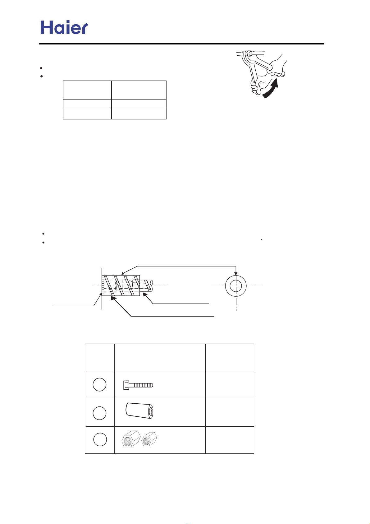
Commercial Air Conditioner Model: AU242FHBIA,
AU482FIBIA, AU48NFIBJA
Cfee\Zk`fe f] i\]i`^\iXek g`g\
Cfe[lZk ]cXi\[ Zfee\Zk`fe nfib kf Zfee\Zk Xcc i\]i`^\iXek g`g\j4
S_\ Zfee\Zk`fe f] `e[ffi le`k g`g\j dljk lj\ [flYc\ jgXee\ij4
S_\ `ejkXcc`e^ kfihl\ j_Xcc Y\ Xj ^`m\e `e k_\ ]fccfn`e^ kXYc\4
Cfee\Zk`e^ g`g\
N4D4/dd0
s<49;
s784=6
IejkXcc`e^ kfihl\
/M3d0
774> /748b^]3d0
:?46 /;46 b^]3d0
DflYc\3jgXee\i
fg\iXk`fe
UXZlld gldg`e^
V`k_ X mXZlld gldg2Zi\Xk\ mXZlld ]ifd k_\ jkfg mXcm\ f] k_\ flk[ffi le`k4
Edgkp`e^ n`k_ i\]i`^\iXek j\Xc\[ `e k_\ flk[ffi le`k `j XYjfclk\cp ]fiY`[[\e4
Ng\e Xcc mXcm\j
Ng\e Xcc k_\ mXcm\j fe k_\ flk[ffi le`k4
GXj c\XbX^\ [\k\Zk`fe
C_\Zb n`k_ X c\XbX^\ [\k\Zkfi fi jfXg nXk\i k_Xk `] k_\i\ `j ^Xj c\XbX^\ Xk k_\ g`g\ Zfee\Zk`fej
Xe[ Yfee\kj4
IejlcXk`fe ki\Xkd\ek
Ng\iXk\ `ejlcXk`fe ki\Xkd\ek fe Yfk_ k_\ ^Xj j`[\ Xe[ c`hl`[ j`[\ f] g`g\j i\jg\Zk`m\cp4
Dli`e^ Zffc`e^ fg\iXk`fe2Yfk_ k_\ c`hl`[ Xe[ ^Xj j`[\j Xi\ Zfc[ Xe[ k_lj j_Xcc Y\ `ejlcXk\[
jf Xj kf Xmf`[ [\n ^\e\iXk`fe4
S_\ `ejlcXk`e^ dXk\i`Xc Xk ^Xj j`[\ j_Xcc Y\ i\j`jkXek kf X k\dg\iXkli\ XYfm\ 786 [\^i\\4
S_\ `e[ffi le`k g`g\ Zfee\Zk`fe gXik j_Xcc Y\ `ejlcXk\[4
Ie[ffi le`k
1??AMMJLQ =M BJGGJP0
Mf4
7
8
S_\ efkZ_ lgnXi[/AkkXZ_\[ [\kX`c m`\n0
F`\c[ g`g`e^ j`[\
RlYj`[`Xip `ejlcXk`fe klY\
AZZ\jjfip gXikj
V`i\ ZcXdg
Pkp4
8
H\Xk
`ejlcXk`fe
j_\Xk_`e^
717
9
RZi\n ZXg
717
-52-
Page 53
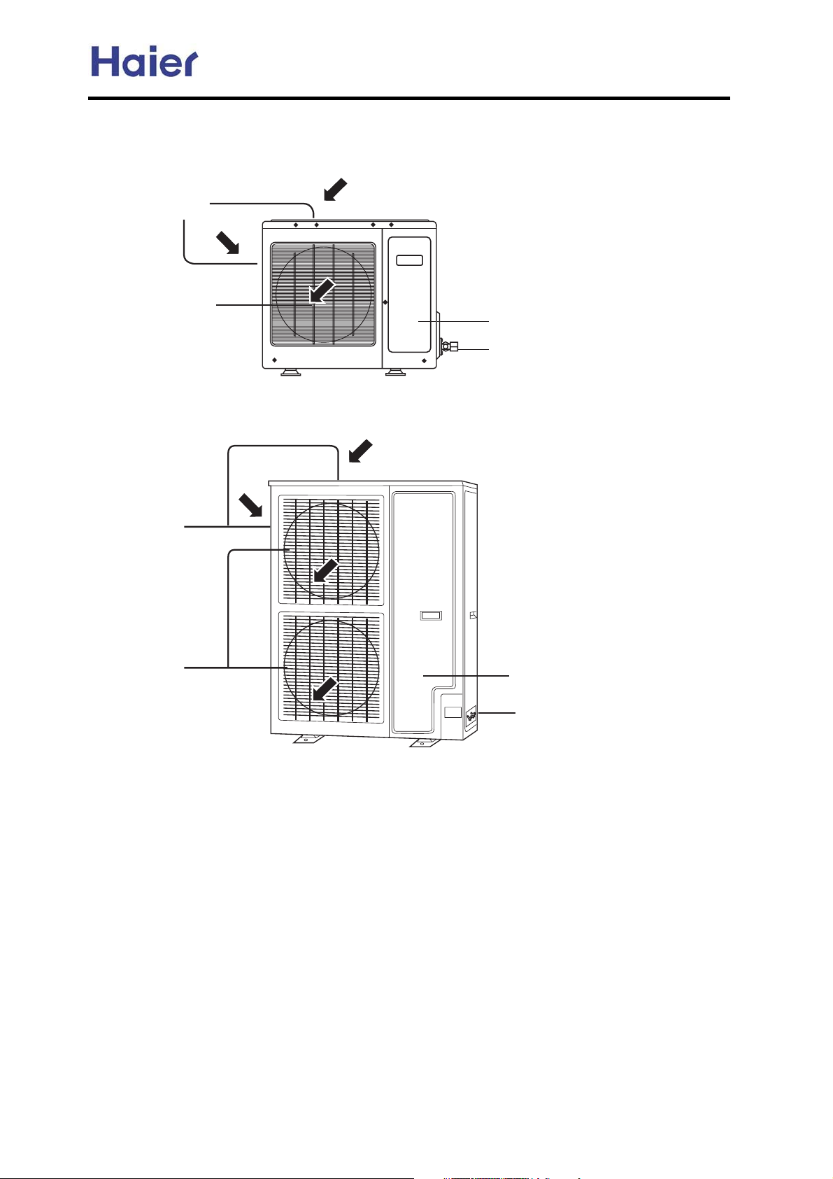
6. Parts and Functions
AU242FHBIA:
DLU LQOHW
DLU RXWOHW JULOOH
AU482FIBIA, AU48NFIBJA:
Commercial Air Conditioner Model: AU242FHBIA,
AU482FIBIA, AU48NFIBJA
FRPSUHVVRUnLQVLGHRI XQLWo
VWRS YDOYH
DLU LQOHW
DLU RXWOHW
FRPSUHVVRUnLQVLGHRI XQLWo
VWRS YDOYH
-53-
Page 54
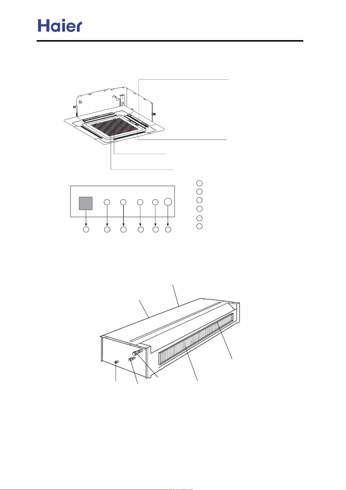
:J[[N\\N ]WR\8
Commercial Air Conditioner Model: AU242FHBIA,
AU482FIBIA, AU48NFIBJA
F_RWP UX]^NZ
+9RZ OUX_ MRZNL\RXW LJW KN JMS][\NM K` ][RWP
\QN FI?B> K]\\XW XW \QN ZNVX\N LXW\ZXUUNZ,
CYNZJ\RWP :XW\ZXU DJWNU
9RZ ?WUN\ >ZRUUN
9RZ =RU\NZ
+?W[RMN XO \QN ?WUN\ >ZRUUN,
CYNZJ\RWP :XW\ZXU DJWNU
a b c d e
Ceiling concealed unit:
:CAD G?A<E CD<E DCI<E
IDQnLQVLGHo
PRWRUnLQVLGHo
<A<E
f
ENVX\N ZNLNR^NZ
a
b
:XVYZN[[XZ @JVY
c
G?A<E @JVY
d
CD<E9G?CB @JVY
DX_NZ @JVY
e
f
<VNZPNWL` [_R\LQ
GUDLQDJHSLSH
OLTXLG SLSH
DLU RXWOHW JLOOH
JDVSLSH
HYDSRUDWRU
-54-
Page 55
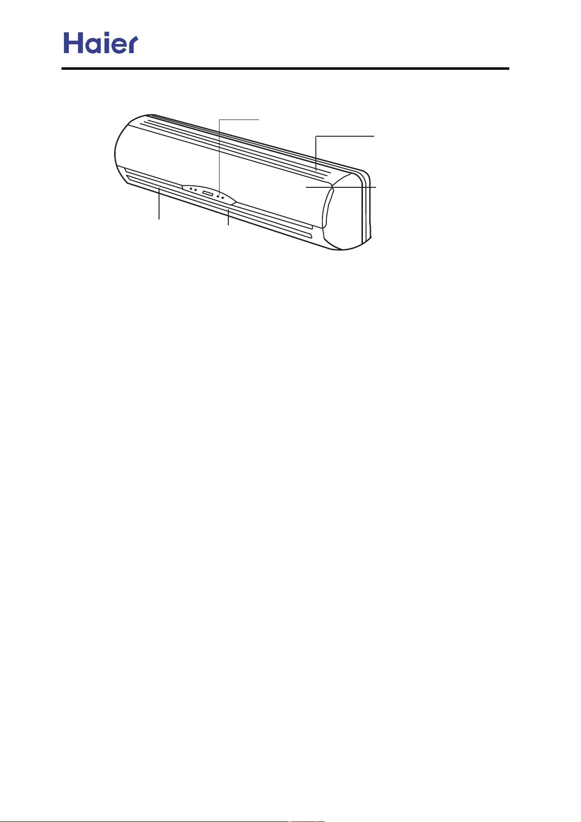
Wall mounted unit:
Commercial Air Conditioner Model: AU242FHBIA,
AU482FIBIA, AU48NFIBJA
VLJQDO UHFHLYHU ZLQGRZ
DLU LQOHW JULOOH
DLU RXWOHW JULOOH
2DLHU
ORXYHU
DLU ILOWHUnLQVLGHo
-55-
Page 56
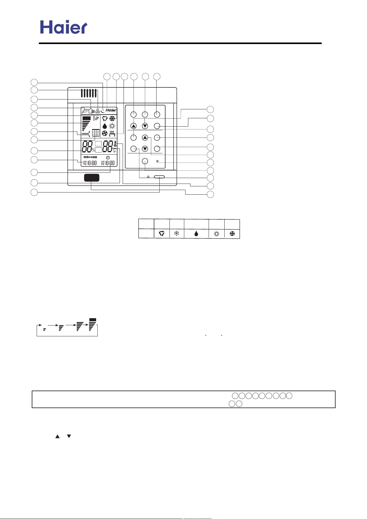
7. Controller functions
7 NQ q|0xw v-,20-**x0 slM`PV
su
st
ss
sr
{
\onj
z
y
x
w
v
u
t
s
QNjiOjaa u322-,
o1xw 2- 230, -,O-yy 3,|2
RNnx+.x0t230xw|1.*t7
SN^*-v~ w|1.*t7
TNn|+x0 jiOjaa w|1.*t7
UNc3+|w|27 w|1.*t7
VN\|0 y|*2x0 v*xt,|,zw|1.*t7
q{x,2{x0x|1 2-- +3v{ w312 v-**xv2xw -,
2{x t|0 |,*x2L 2{x 5|0xv-,20-**x05|** 1{-5
2{|1 w|1.*t72-0x+|,w 2{x31x02-v*xt,2{x
t|0 |,*x2N\y2x0 v*xt,|,zt,w|,12t**t2|-,L
}312 .0x11 2{x t|0 y|*2x00x1x2 u322-,
WNm3.x0Om-y2-.x0t2|-, w|1.*t7
XNat,1.xxw w|1.*t7
g-5 at, hxw at, c|z{ at, \32-
|
YN\32- m5|,zw|1.*t7
QPNcxt*2{ 12t2xw|1.*t7
QQNa0x1{t|012t2xw|1.*t7
QRNc3+|w|y7|,z 12t2xw|1.*t7
QSNm*xx.12t2xw|1.*t7
sv sw sx sy sz
PDQ
PRO
N
@ihc
Commercial Air Conditioner Model: AU242FHBIA,
AU482FIBIA, AU48NFIBJA
s{
a\i mqdib
hj_`
n`hk
c`\gnc
^gj^f
ndh`l
adgn`l l`m`n
jiOjaa
m`n
mg``k
l`m`n
QTNix25-0~v-,20-* w|1.*t7
QUNq-0~|,z +-wx w|1.*t7
Scf_]b[
@ihc
Bcc`]b[
acXY
S]fY
Wcbhfc``Yf
cdYfUh]cb
cdYfUh]cb
CY\ia]X]Zm]b[
cdYfUh]cb
QVN`*xv20|v {xt2|,zw|1.*t7
QWNj.x0t2|-, +-wx u322-,
o1xw 2- 1x2 5-0~|,z +-wxZ
\32-L ^--*|,zL _x{3+|w|y7|,zL
cxt2|,zL at,
QXNat,1.xxw u322-,
1xw 2- 1x2 yt,1.xxwZ g-5
o
at,L hxw at,L c|z{ at,L \32-
QYNm5|,zu322-,
o1xw 2- 1x2 \32- m5|,z -0
a|6xw t|01x,w|,zw|0xv2|-,
RPNnx+.x0t230xmx22|,zu322-,
o1xw 2- 1x22x+.x0t230xL
2x+.x0t230x 0t,zxZQV^9SP ^
RQN^*-v~ u322-,
o1xw 2- vt*|u0t2x 2{x 2|+x -y
2|+x0 t,wv*-v~
tr
t{
ts
tt
tu
tv
tw
tx
ty
tz
ur
GYUh]b[
cdYfUh]cb
EUb
cdYfUh]cb
RRNmx22|,zu322-,
o1xw 2- v-,y|0+
2{x 2|+x -y 2|+x0
t,wv*-v~
RSNm*xx. u322-,
o1xw 2- 1x2 m*xx.
12t2x
RTNn|+x \w}312|,z
u322-,
o1xw 2- tw}312 2{x
2|+x -y 2|+x0 t,w
v*-v~
RUNlx1x2 u322-,
q{x,2{x 5|0x
v-,20-**x0 t..xt01
tu,-0+t* v-,w|2|-,L
31xt1{t0.M.-|,2xw
t02|v*x 2- .0x11 2{|1
u322-, 2- +t~x 2{x
5|0xv-,20-**x0
0x13+x ,-0+t*
RVN\|0 a|*2x0 lx1x2 u322-,
\y2x0 v*xt,|,z 2
{x
t|0 |,*x2L .0x11 2{|1
u322-,L 2{x 3,|2
vt,12t02 2- -.x0t2x
RWNn|+x0 u322-,
o1xw 2- 1x22{x
+-wx -y 2|+x0
RXNg-v~ 12t2xw|1.*t7
RYNcxt*2{
o1xw 2- v-,20-* 2{x
0t2|,z -67zx,
zx,x
y3,v2|-, t,w ,xzt2|4x
|-,My3,v2|-,
SPNlx+-2xv-,20-* 5|,w-5
o1xw 2- 0xvx|4x 2{x
0x+-2xv-,20-* 1|z,t*
i-2xZ
QNn{|1+-wx* w-x1 ,-2 {t4x 2{x y-**-5|,z 0x*t2xw w|1.*t7 t,wy3,v2|-,
RNn{x -32w--0 3,|2,--67zx,Mut0 y3,v2|-, -0 ,- ,xzt2|4x|-, 3,|2,- {xt*2{y3,v2|-, t,w {xt*2{w|1.*t7N
w x y { ss
t{sr
st
tx
sx
sv
M]ge^l]neji jb _gj_f
q{x, 230,|,z -, 2{x 3,|2 y-0 2{x y|012 2|+xL 2{x v
*-v~ 1{-3*wuxvt*|u0t2xwN n{x +x2{-w -yvt*|u0t2|-, |1Z
QNk0x11 G^*-v~G u322-,L 2{x ^*-v~ w|1.*t7 G \hGGkhG 5|** y*t1{N
RNk0x11 -0 2- tw}312 2|+xN a-0 xtv{ .0x11L 2{x 2|+x 5|** |,v0xt1x -0
wxv0xt1x Q +|,32xN dy wx.0x11|,z
2{x u322-,L 2{x 2|+x 5|** |,v0xt1x -0 wxv0xt1x 0t.|w*7N
SN\y2x0 v-,y|0+|,z 2{x 2|+xL .0x11 G mx2G u322-,LG\hG -0 G khG 5|** 12-. y*t1{|,zL2{x v*-v~ 5
-56-
|** uxz|,2-5-0~N
Page 57
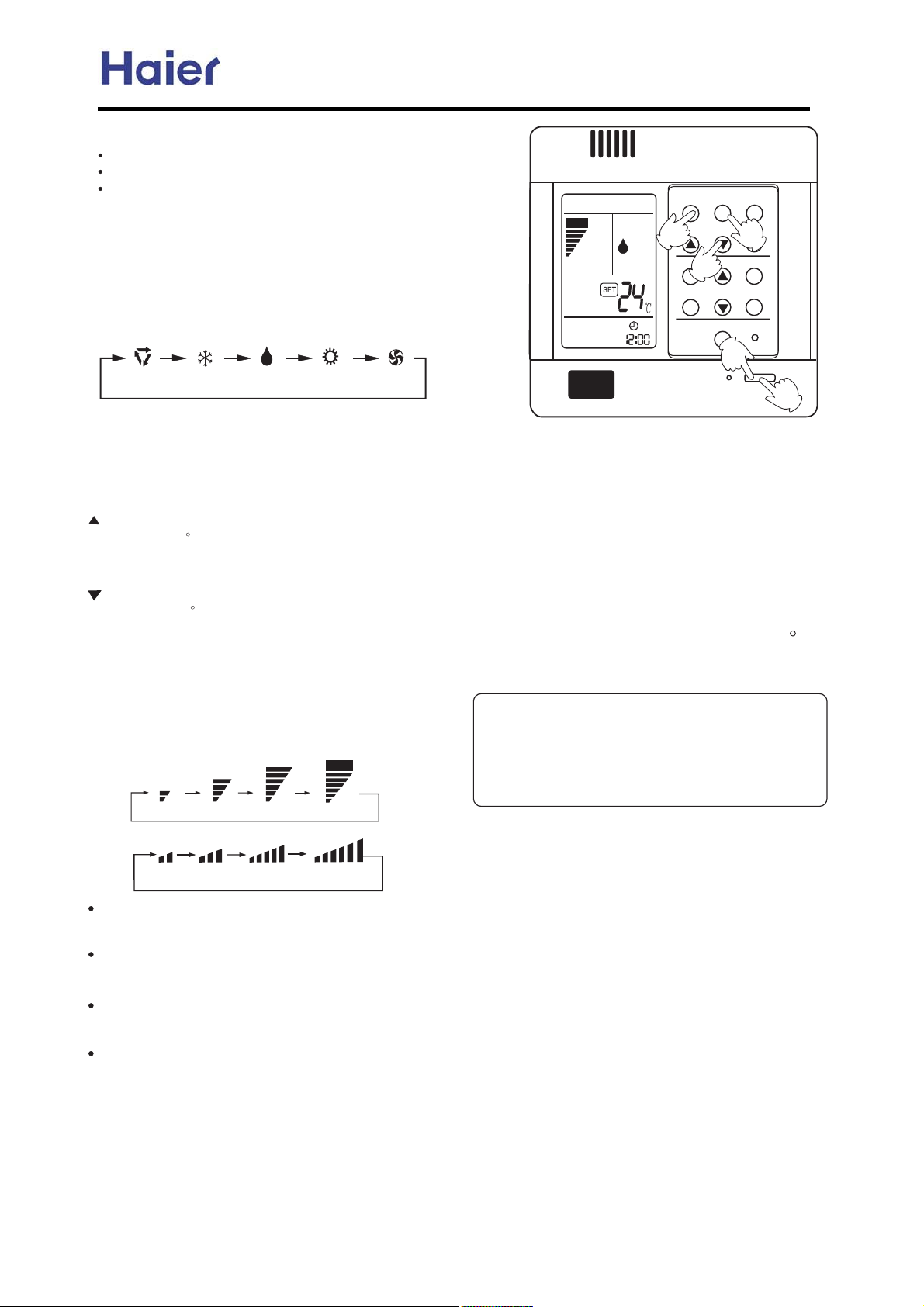
Commercial Air Conditioner Model: AU242FHBIA,
lxv-++x,wt2|-,1
o1x ^jjg |, 13++x0N
o1x c`\n |,5|,2x0N
o1x_ls|, 1.0|,zLt323+, t,w|, wt+. v*|+t2xN
IQJ o,|212t02
k0x11 jiOjaa u322-,L 3,|212t021N
k0x4|-31 -.x0t2|-, 12t231 t..xt01 -, w|1.*t7
Ii-2 n|+x01x22|,zJN k-5x0 |,w|vt2-0 *|z{21 3.N
IRJ mx*xv2-.x0t2|-, +-wx
k0x11 hj_` u322-,N a-0 xtv{ .0x11L -.x0t2|-,
+-wx v{t,zx1 t1 y-**-51Z
\onj ^jjg _ls a\ic`\n
o,|25|** 03, |,-.x
g^_Nm2-. w|1.*t7 t2 7-30 wx1|0xw +-wxN
ISJ mx*xv22x+.N 1x22|,z
k0x11 n`hk u322-,
`4x07 2|+x 2{x u322-, |1.0x11xwL 2x+.N 1x22|,z
|,v0xt1x1 Q ^N
dy u322-, |1 ~x.2 wx.0x11xwL 2x+.N1x22|,z 5|**
|,v0xt1x /3|v~*7
`4x07 2|+x 2{x u322-, |1.0x11xwL 2x+.N 1x22|,z
wxv0xt1x1 Q ^N
dy u322-, |1 ~x.2 wx.0x11xwL 2x+.N 1x22|,z 5|**
wxv0xt1x /3|v~*7N
o,|25|** 12t02 03,,|,z 2- 0xtv{ 2{x 2x+.N 1x22|,z
-, g^_N
ITJ at,1.xxw 1x*xv2|-,
k0x11 a\i u322-,N a-0 xtv{ .0x11L
yt,1.xxw v{t,zx1 t1 y-**-51Z
q|0xw v-,20-**x0
0t2|-, +-wx w|1.*t7xw -,
N
@RQM
AU482FIBIA, AU48NFIBJA
mqdib
a\i
hj_`
\onj
6
^gj^f m`n
ndh`l mg``k
\h
n`hk
7
adgn`l l`m`n
c`\gnc
8
l`m`n
9
jiOjaa
5
o,|2 03,1 t22{x 1.xxw w|1.*t7
xw -, g^_Nd,
c`\n +-wxL 5t0+ t|05|** u*-5 -32 ty2x0 t
1{-02 .x0|-w -y 2|+xw3x 2- v-*wMw0ty2.0x4x,2|-,
y3,v2|-,N
d, _ls +-wxL 5{x, 0--+ 2x+.N uxv-+x1 R ^
{|z{x02{t,2x+.N 1x22|,zL 3,|25|** 03, |,2
x0+|22xM
,2*7 t2 gjq 1.xxw 0xzt0w*x11 -ya\i1x22|,zN
IUJ o,|2 12-.
k0x11 jiOjaa u322-,N
j,*7 2|+xt,w 0--+ 2x+. 0x+t|,1 -, g^_N
\** |,w|vt2-01 z- -32N
px02|vt* y*t. v*-1x1 t32-+t2|vt**7N
c|,21
q|0xv-,20-**x0 vt,+x+-0|8x xtv{ -.x0t2|-,
12t231N
q{x,12t02|,z|2,x62 2|+xL }312 .0x11 jiOjaa
u322-, t,w 3,|25|** 03, |,.0x4|-31 12t231N
gj
hd cdb
lx+-2xv-,20-**x0
hd
gj
cdb
\on
\on
x
.
*
\32- 03,,|,zZ _30|,z 2{x \32- 03,,|,z +-wxL t|0 v-,w|2|-,|,z 03,,|,zt,wvt, t32-M1x*xv22{x
v--*|,zL{xt2|,zL yt,+-wx tvv-0w|,z 2- 2{x 0--+ 2x+.x0t230xN
at, 03,,|,zZ n{x \^ -,*7 {t4xt|0 13..*7 03,,|,z ,- v--*|,zt,w {xt2
|,z 03,,|,zt22{x v-,w|2|-,L
\^ vt,H2 {t4xt32- t|0 13..*7 03,,|,zL t,wvt,H2 w|1.*t72{x 1x22|,z 2x+.x0t230x 4t*3x -, 2{x g^_N
_30|,z 2{x {xt2|,z 03,,|,zL ty2x012t02 2{x \^L |,-0wx02-.0x4x,2 v--*xw t|0L \^ vt, 12-. y
-0 t
5{|*x uxy-0x 1x,w {xt2 t|0N
_30|,z 2{x wx{3+|y|vt2|-, 03,,|,zL 5{x,2{x 0--+ 2x+.N 1x22|,z 2x+.NL,-2 1x22|,zv-,w|2|-,
tvv-0w|,z 2- 2{x t|01.xxwN
-57-
Page 58
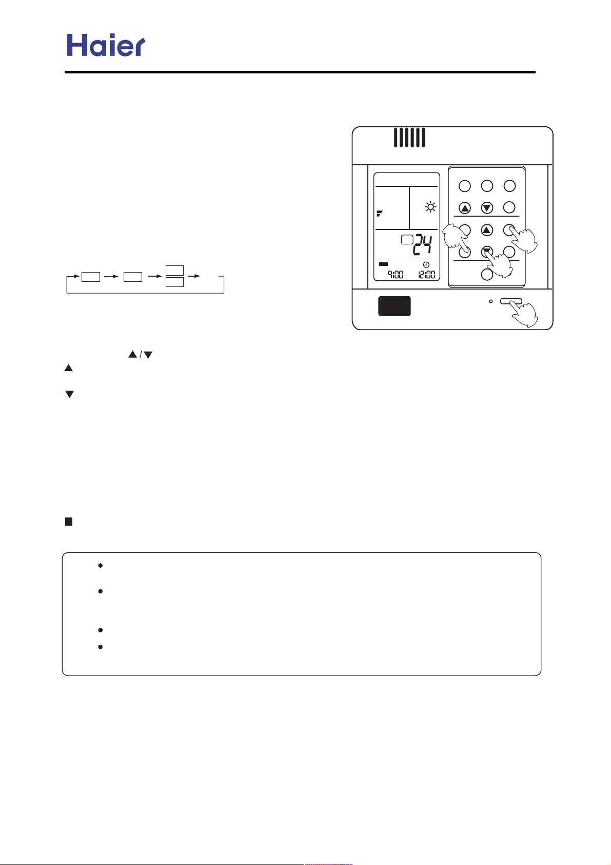
Commercial Air Conditioner Model: AU242FHBIA,
Yan Mgj_f _jlla_ngq ^abjla mn]lneic Zehal jkal]nejiC
s-3 vt,*x23,|212t02 -0 12-. t32-+t2|vt**7 t2 y-**-5|,z 2|+xZ ]xy-0x
7-3 5t~x 3. |,2{x +-0,|,zL -0 zx2 utv~ y0-+ -321|wx -0 ty2x0 7-3
yt** t1*xx. t2,|z{2N
ndh`l jiOjaa
@DAKbnal oien mn]lnB maga_n qjol
`amela` jkal]neji hj`aC
j.x0t2|-, +-wx 5|** ux w|1.*t7xw
-, g^_Nk-5x0 |,w|vt2-0 *|z{21 3.N
@EAZRTOX hj`a maga_neji
k0x11 ndh`l u322-, 2- v{t,zx
ndh`l +-wxN`4x07 2|+x 2{x
u322-, |1.0x11xwL w|1.*t7
v{t,zx1 t1 y-**-51Z
ML
MEE
ML
MEE
V`Ub_
m`n
ML
\h \h
AU482FIBIA, AU48NFIBJA
a\i
hj_`
n`hk
^gj^f m`n
6
ndh`l mg``k
mqdib
c`\gnc
8
o
adgn`l l`m`n
ODPDQ
7
mx*xv2 7-30 wx1|0xw ndh`l +-wx
jiOjaa
Iji -0 jaaJ
@FAZehal manneic
k0x11 ndh` u322-,N
`4x07 2|+x 2{x u322-, |1.0x11xwL 2|+x|,v0xt1x1 QP+|,Ndy u322-, |1 ~x.2
wx.0x11xwL 2|+x 5|** v{t,zx /3|v~*7N
`4x07 2|+x 2{x u322-, |1.0x11xwL 2|+x wxv0xt1x1 QP+|,Ndy u322-, |1 ~x.2 wx.0x11xwL
2
|+x 5|** v{t,zx /3|v~*7N
n|+x 5|** ux 1{-5, -, g^_N d2 vt, ux tw}312xw 5|2{|, RT{-301N
@GAMjibelheic qjol manneic
\y2x01x22|,zv-00xv22|+xL .0x11 m`n u322-, 2- v-,y|0+ GjiG -0 GjaaG 12-.1 y*t1{|,zN
n|+xw|1.*t7xwZ o,|212t021 -0 12-.1 t26{-306+|, Iji -0 jaaJN n|+x0+-wx |,w|vt2-0 *|z{21 3.N
Zj _]i_ag ZRTOX hj`a
e312 .0x11 ndh`l u322-, 1x4x0t*2|+x1 3,2|* ndh`l +-wx w|1t..xt01N
\vv-0w|,z 2- 2{x 1x2|,z 2|+|,z -.x,L v*-1x 1x/3x,vxL vt,0xt*|8xy|012 -.x,2{x, v-*1x 2{x 3,|2
-0 y|012 v*-1x 2{x,-.x,2{x 3,|2N
QeinmJ
q|0xv-,20-**x0 .-11x11x1+x+-07 y3,v2|-,L 5{x,31x ndh`l +-wx ,x62 2|+xL }312
.0x11 m`n u322-, ty2x0+-wx 1x*xv2|,z|y2|+x01x22|,z|12{x 1t+xt1.0x4|-31 -,xN
q|0x 0x+-2xv-,20-**x0-00x+-2xv-,20-**x0 vt,+x+-0|8x xtv{ 5-0~|,zv-,w|2|-,N ix62
2|+x -.x,2{x 3,|2L -,*7 ,xxw 2- .0x11 2{x jiOjaa ~x7L 2{x \^ vt, 5-0~ tvv-0w|,z 2-
*t12 2|+x 5-0~|,zv-,w|2|-,NIn|+|,zL m*xx.|,zt,wm5|,z
+-wx ,-2 |,v*3wxwNJ
a0-+ n|+|,zv*-1x 2- 2|+|,z -.x,L vt,1x22|,z 1*xx.+-wxN
5
k*xt1xv*-1x {xt*2{y3,v2|-, y|012 uxy-0x 1x22|,zn|+x0L 2{x, 7-3 vt, w-2{x ndh`l ji
-.x0t2|-,Nk*xt1xw- ,-2 31x 2{x {xt*2{y3,v2|-, 5{x, |, ndh`l ji 12t2xN
-58-
Page 59
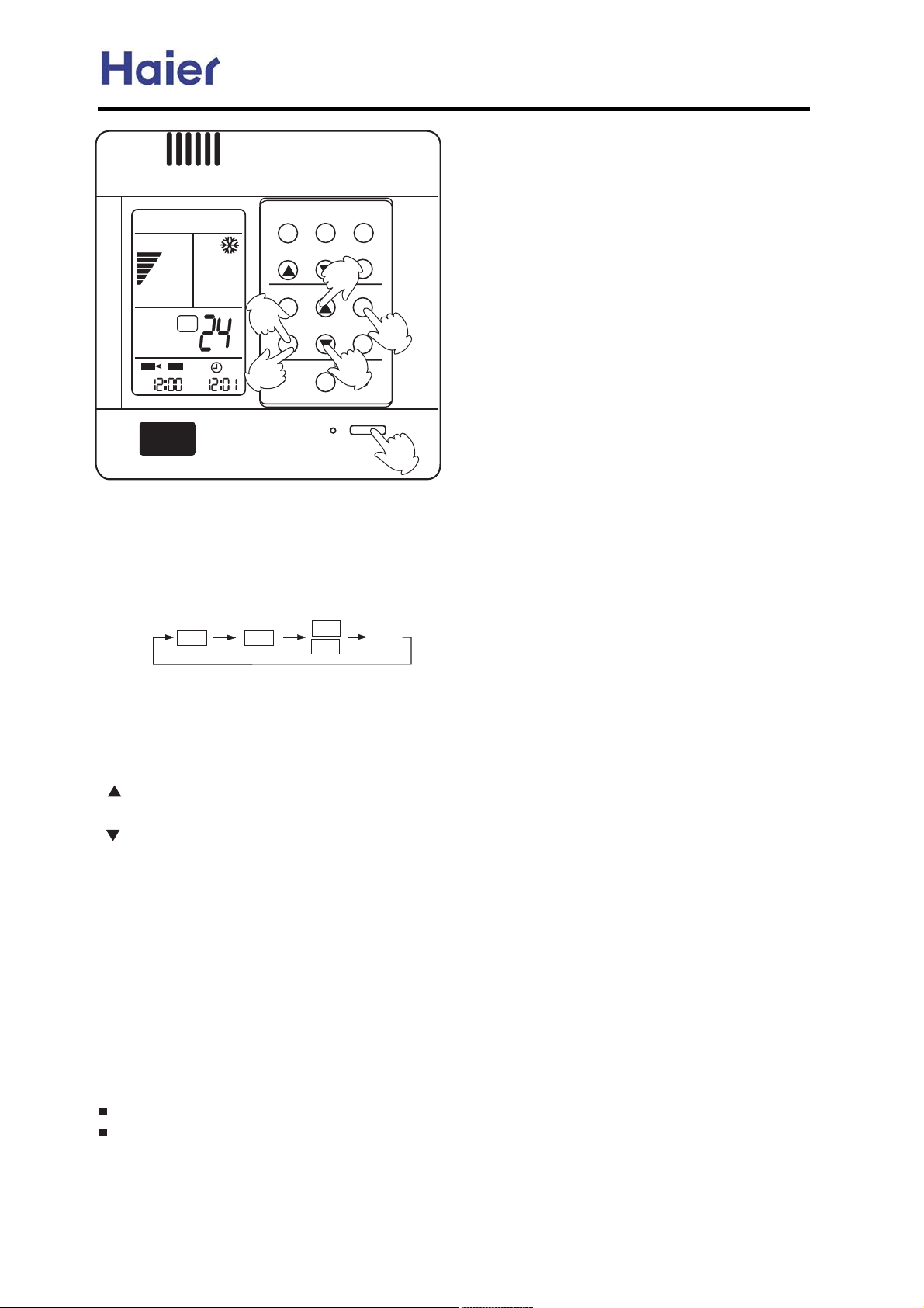
hj_`
Commercial Air Conditioner Model: AU242FHBIA,
AU482FIBIA, AU48NFIBJA
a\i
mqdib
ji jaa
kh
m`n
n`hk
^gj^f m`n
6
ndh`l mg``k
o
\h
8
jiOjaa
c`\gnc
7
adgn`l l`m`n
ODPDQ
9
:
5
ndh`l jiMjaa
@DAKbnal oien mn]lnB maga_n qjol `amela` jkal]neji hj`a
j.x0t2|-, +-wx 5|** ux w|1.*t7xw -, g^_N k-5x0 |,w|vt2-0 *|z{21 3.N
@EA Wlamm ZRTOX ^onnji nj _d]ica ZRTOX hj`a
`4x07 2|+x 2{x u322-, |1.0x11xwL w|1.*t7 v{t,zx1 t1 y-**-51Z
mx*xv2 N
ji
jaa
ML
MEE
ML
MEE
V`Ub_
@FAZeha manneic bjl ZRTOX VU
k0x11 ndh` u322-,N
`4x07 2|+x 2{x u322-, |1.0x11xwL 2|+x|,v0xt1x1 QP+|,Ndy u322-, |1 ~x.2 wx.0x11xwL 2|+x 5|** v{t,zx
/3|v~*7N
`4x07 2|+x 2{x u322-, |1.0x11xwL 2|+x wxv0xt1x1 QP+|,Ndy u322-, |1 ~x.2 wx.0x11xwL 2
|+x 5|** v{t,zx
/3|v~*7Nn|+x 5|** ux 1{-5, -, g^_Nd2 vt, ux tw}312xw 5|2{|, RT{-301N
\h 0xyx01 2- +-0,|,zt,wkh2- ty2x0,--,N
@GA Zeha _jibelheic bjl ZRTOX
\y2x02|+x 1x22|,zL .0x11 ndh`l u322-, 2- v-,y|0+NGjiG 12-.1 u*|,~|,zL q{|*x GjaaG 12t021 u*|,~|,zN
n|+xw|1.*t7xwZ o,|212t021 t2 r{-30 r +|,N
@HAZeha manneic bjl ZRTOX VPP
a-**-5 2{x 1t+x .0-vxw30x1 |, Gn|+x 1x22|,zy-0 ndh`l jiGN
@IAZeha _jibelheic bjl ZRTOX VPP
\y2x02|+x 1x22|,zL .0x11 m`n u322-, 2- v-,y|0+GjaaG 12-.1 y*t1{|,zN
n|+xw|1.*t7xwZ o,|2 12-.1 t2 r{-30 r +|,N
Zj _]i_ag ZRTOX hj`a
e312 .0x11 ndh`l u322-, 1x4x0t*2|+x1 3,2|* ndh`l +-wx w|1t..xt01N
\vv-0w|,z 2- 2{x n|+x 1x22|,z 1x/3x,vx -y ndh`l ji -0 ndh`l jaaL x|2{x0 m2t02Mm2-. -0 m2-.Mm2t02
vt, ux tv{|x4xwN
-59-
Page 60
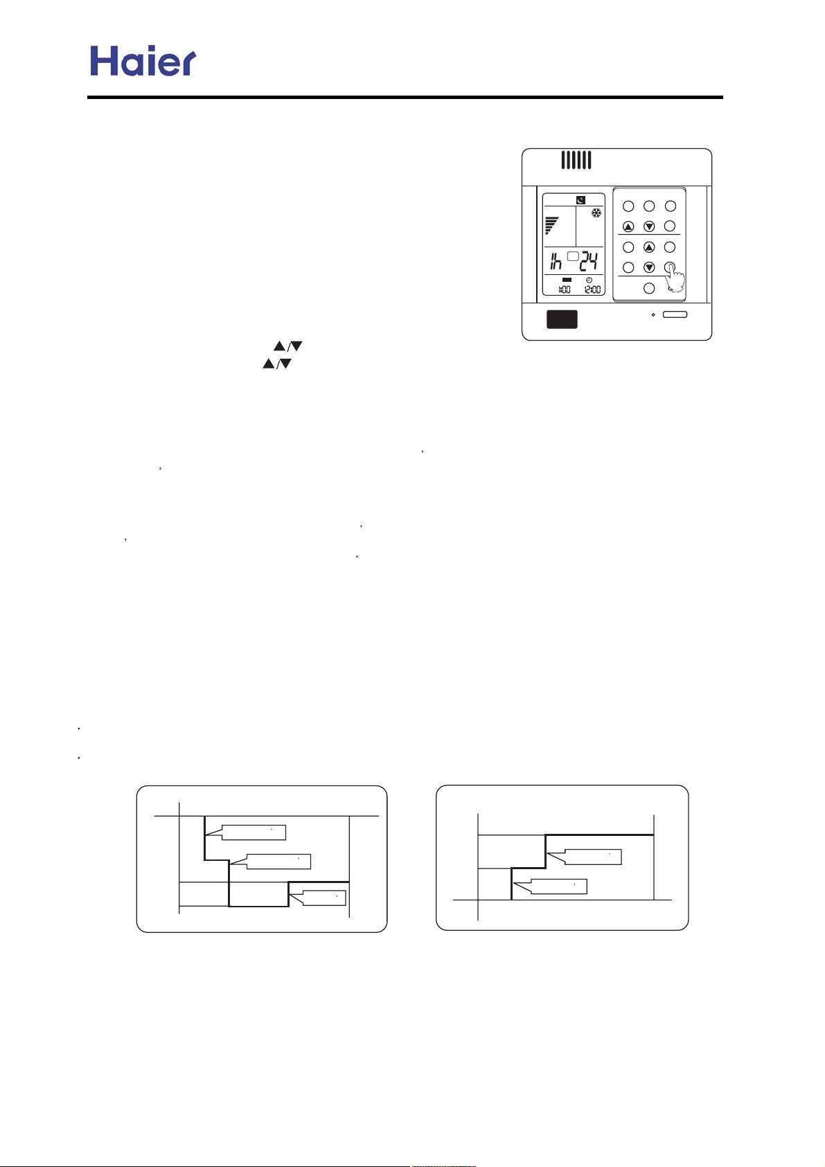
Commercial Air Conditioner Model: AU242FHBIA,
AU482FIBIA, AU48NFIBJA
YSOOW
i-2xZ ]xy-0x 31|,z 2{|1 y3,v2|-,L +312 tw}312 2{x
v*-v~L -0 2{x 1*xx. y3,v2|-, 5|** ux w|1-0wx0xwN
mqdib
a\i
^-+y-02tu*xm*xx.
\2,|z{2L uxy-0xz-|,z 2- uxw 7-3 vt,.0x11
w-5, 2{x mg``k u322-, -, 2{x v-,20-**x0
t,w 2{x t|0Mv-,w|2|-,x05|** 03, u72{x
v-+y-02tu*x 1*xx.|,z +-wx 2- +t~x 7-3 1*xx.
+-0xv-+y-02tu*xN
m`n
jaa
\h
\h
k0x11 mg``k u322-, -,vx 2- +t~x 2{x t|0 v-,w|2|-,x0 {t4x
2{x .0xM1x21*xx.2|+x Iy|012 .-5x0M-, |1 GQ{GJL 2{x 1*xx. 17+u-*
5|** t..xt0N k0x11 2|+xu322-, L 7-3 vt,1{--1x 2{x 2|+x
|, Q9X {-301N `tv{ .0x11 -y L 2{x 2
|+x|,v0xt1x1O0xw3vx1
Q{-30 t,w G6{G t..xt0 |,2{x {3+|w|27 1x22|,zt0xtLGjaaG t..xt01
|, Gndh`l jaaG w|1.*t7 t0xt t,w 2|+x0M-yy 2|+x[ .0x11 mg``k
u322-, tzt|,2-vt,vx*1*xx. y3,v2|-,L 2{x 1*xx
. 17+u-* w|1t..xt01N
Ri _jjgeicB `adohe`ebqeic hj`a
j,x{-30 ty2x01*xx.|,z -.x0t2|-, 12t02L 2{x 2x+.N |1 Q {|z{x02{t,2{x 1x22|,z -,xN \y2x0 t,-2{x0 {-30 2{x
2x+.N 0|1x1 Q t,w 2{x, 03, v-,2|,3-31*7 y-0 t,-2{x0 V{01H t,w 2{x, v*-1xN n{x tv23t*2
B
B
2{x 1x22|,z -,x 5{|v{ |12-.0x4x,2 y0-+ ux|,z 2-- v--* 2- 7-30 1*xx.N
Ri da]neic hj`a
j,x{-30 ty2x012t02 3.L 2{x 2x+.N wxv0xt1x R *-5x02{t,2{x 1x22|,z -,xN \y2x0 t,-2{x0 {-30 wxv0xt1xu7
+-0x RN
B
n{x 2x+.x0t230x 5|** t32-+t2|vt**7 0|1xu7 Q ty2x0 t,-2{x0 S{01H -.x0t2|-,L t
B
B
,w 2{x, t32-+t2|vt**7 v*-1x
ty2x0 S{01H v-,2|,3-31 -.x0t2|-,N n{x tv20t*2x+.x0t230x|1 *-5x02{t,2{x 1x22|,z -,x 5{|v{ |12-.0x4x,2
y0-+ ux|,z 2-- {-2 2- 7-30 1*xx.N
UjnaJ d, \onj +-wxL 3,|25|** 03, |, mg``k y3,v2|-, tvv-0w|,z 2- 2{x -.x0t2|-, +-wxN
\y2x01x22|,z mg``k y3,v2|-,L |2 |1 y-0u|wwx,2-vt*|u0t2xv*-v~N
dy 2{x 1x21*xx.M2|+xw-x1 ,-2 0xtv{ X {-301L 2{x 3,|25|** 12-. -.x0t2
|-, t32-+t2|vt**7 ty2x01x22|+x
|1 v-+.*x2xN
mx2 Gndh`lMjaaG y3,v2|-, y|012L 2{x,1x2 mg``kL t,w 2{x 1*xx.M1x2 |1.x0y-0+t,vx[ 1x2 ndh`lMji
y3,v2|-, y|012L 2{x 1*xx. y3,v2|-, vt, -,*7 ux 1x2
uxy-0x ndh`lMji[ |y 1x22{xmg``k y3,v2|-, y|012L
2{x ndh`l y3,v2|-, vt, ,-2 ux 1x2N
\y2x01x22|,z 1*xx. y3,v2|-,L ,-2 t**-5xw 2- tw}312 2{x v*-v~N ^t,H231x 2{x 0x+-2xv-,20-**x0-.x0t2x 2{x
dy 1-L .*xt1xvt,vx*2{x 1*xx. y3,v2|-, y|012N
\^N
\y2x01x22|,z 1*xx. y3,v2|-,L vt,H21x22{x 2|+|,zy3,v2|-,N
hj_`
n`hk
c`\gnc
^gj^f m`n
ndh`l mg``k
;
adgn`l l`m`n
l`m`n
jiOjaa
x+.N |1 {|z{x02{t,
m`nndib n
5\f
mg``k loi ]`bdim mg``k loi mnjkm
wxv0xt1x R
5\f
cxt2+-wx
B
wxv0xt1x1 R
S {01
B
tu-32 S {01
|,v0xt1xQ
mcon _jqi
B
mg``k loi ]`bdim
m`nndib n
-60-
Q {0
tu-32 V {01
Q {0
|,v0xt1x Q
|,v0xt1x Q
^--*|,z +-wx
mg``k loi mnjkm
^
^
mcon _jqi
Page 61
Commercial Air Conditioner Model: AU242FHBIA,
AU482FIBIA, AU48NFIBJA
Konj lamn]ln boi_neji @nj ^a ]kkgea` bjl ] ia_amm]lq meno]nejiA
\y2x02{x t32-M0x12t02 y3,v2|-, |11x2L |y .-5x0 yt|*30x 13wwx,*7 -vv301 5{|*x 2{x t|0 v-,w|2|-,x0
|1 5-0~|
mx22|,zhx2{-wZ q{x,2{x 0x+-2xv-,20-**x0 |1-,Ix6v*3w|,z 2|+x0+-wx t,wyt,+-wxJL .0x11
2{x Gmg``kG u322-, -, 2{x 0x+-2xv-,20-**x0 QP 2|+x15|2{|, U 1xv-,w1L t,wty2x02{x u388x0
0|,z1 T 2|+x1L 2{x t|0
^t,vx* hx2{-wZ k0x11 2{x Gm*xx.|,zG u322-, -, 2{x 0x+-2xv-,20-**x0 QP 2|+x15|2{|, U 1xv-,w1L
t,wty2x02{x u388x00|,z1 R
i-2x1Z q{x, t .-5x0 yt|*30x 13wwx,*7 -vv301 w30|,z 2{x t|0 v-,w|2|-,x0 |1 5-0~|,zty2x02{x .-5x0
yt|*30xv-+.x,1t2|-, |11x2L |y 2{x t|0 v-,w|2
.-5x0 13..*7 2- .0x4x,2 |21 -.x0t2|-, y0-+ ux|,z 0x13+xw ty2x02{x .-5x0 |1 13..*|xw tzt|,L -0
.0x11 2{x Gm5|2v{ j,OjyyG u322-, ty2x02{x .-5x0 v-+x1 tzt|,Ndy 2{x v-,20-**x0,-1*xx
2{x G15|,zG ~x7 |,12xtw 2{x G1*xx.|,zG -, 1x22|,z 2{x t32- 0x12t02 y3,v2|-,N
^-,vx0,|,zhlp\32- lx12t02 y3,v2|-, y-0 cMhlp +-wx*1
lxt1-,
ct|x0L cx0x5|2{
kga]ma h]fa mola pdai nda kjpal em mdon `jpi pdandal ]lnebe_e]ggq jl ]__e`ain]ggqB nda pdjga
mqmnah ei_go`eic jon`jjl oien ]i` ]gg nda ei`jjl oienm homn ^a jbbC Rb qjo `j ijn h]fa nda
eimn]gg]neji ]m jol ei`e_]nejiB Q]eal pegg ijn ^a lamkjime^ga bjl ]iq klj^gah lamogneic bljh ndemC
,zL |25|** 0x13+x 2{x .0x4|-31 5-0~|,z 12t2x 5{x,2{x .-5x0 |1 13..*|xw tzt|,N
v-,w|2|-,x05|** x,2x02{x 12t2x -yt32-M0x12t02 y3,v2|-,N
2|+x0L 2{x .-5x0 yt|*30xv-+.x,1t2|-, +-wx 5|** ux vt,vx**xwN
|-,x05|** ,-2 ux 31xw y-0 t *-,z 2|+xL .*xt1xv32 -yy 2{x
ct|x0 \32- lx12t02 y3,v2|-, 5{x,2{x 3,|2 .-5x0 w0-.1 w-5, 13wwx,*7L 2{x 3,|2+|v0-.0-vx11-0
5|** 12-0x 2{x .0x4|-31 5-0~|,zv-,w|2|-, t,w 5{x,2{x .-5x0 |1-,tzt|,L 2{x 3,
+x+-07N
\32- lx12t02 y3,v2|-, |1 wx1|z,xw ut1|vt**7 -, 2{x hlp 5{-*x 1712x+L u32 |2 |113|2tu*xy-0 xtv{
|,w--0 3,|2 |,w|4|w3t**7N
dy 1-+x -y|,w--0 3,|21 .-5x0 v32 w-5,L u32 2{x -32w--0 3,|2 t,w 2{x
+t7ux .0-u*x+1 5|** {t..x,13v{ t1 y0xx8|,zt2 v--*|,z +-wx t,w -4x0*-tw .0-2xv2|-, t2
{xt2|,z +-wx -, 2{-1x|,w--0 3,|21 5|2{-32 .-5x0N
q{x,-,x -0 1-+x|,w--0 3,|21 .-5x0 w0-.1 w-5, t,
|,w--0 3,|21 5|2{-32 2{x .-5x0L 5|** ~xx.2{x .0x4|-31 5-0~|,zv-,w|2|-, uxy-0x 2{x .-5x0 |1-yyN
\,wx6.t,1|-, 4t*4x ~xx.1 -.x, t2 t~|,w -y -.x,|,z 0t2xv-,w|
1- 2{x0x|10xy0|zx0t,2 y*-5|,z|,2{x x6v{t,zx0L u32 2{x |,w--0 yt, 12-.1 5-0~|,zN dy 2{x 3,|21 5-0~
t2 v--*|,z +-wxL 2{x |,w--0 3,|21 5|2{-32 2{x .-5x05|** +t7ux +t~x y0xx8|,z
t2 {xt2|,z +-wxL +t7ux 2{x -32w--0 3,|2 v-+.0x11-0 5|** 12-. uxvt31x -y 2{x .0x1130x -0
2x+.x0t230x .0-2xv2|-,N n{|1 |1 -30 wx1|z, ut1|vt**7 -, \32- lx12t02 y3,v2|-, v300x,2*7N
L 1-*x+,*7 |,y-0+1 -30 v312-+x01L |,12t**x01L w|120|u32-01L x2vN pdai h]feic eimn]gg]nejiB
w 2{x -2{x0 |,w--0 3,|21 t0x 12|** 5-0~L 2{x
J
. ~x7 L31x
|25|** 03, t12{|1
-2{x0 |,w--0 3,|21 12|** 5-0~L
2|-, t12{x .0x4|-31 0x/3|0x+x,2L
N dy 2{x 3,|2 5-0~1
[mal M]oneji
\u-32 2{x 0x+-2xv,-20-* -.x0t2|-,L tu-4x -,*7 2t~x 5|0xw 0x+-2xv-,20-**x0 t,w 0x+-2xv-,20-**x0
t1 tx6t+.*xtu-32 2{x 0x+-2xv-,20-**x0 t,w 0x+-2x 0xvx|4x031x +x2{-wL |2 |12{x 1t+x 0x+-2x
v-,20-**x0 L .*xt1x 31x
i-1*xx. y3,v2|-, 5{x,31x 0x+-2xt,w 0x+-2x 0xvx|4x0N
0xyx02-tu-4x +x2{-wN
-61-
Page 62
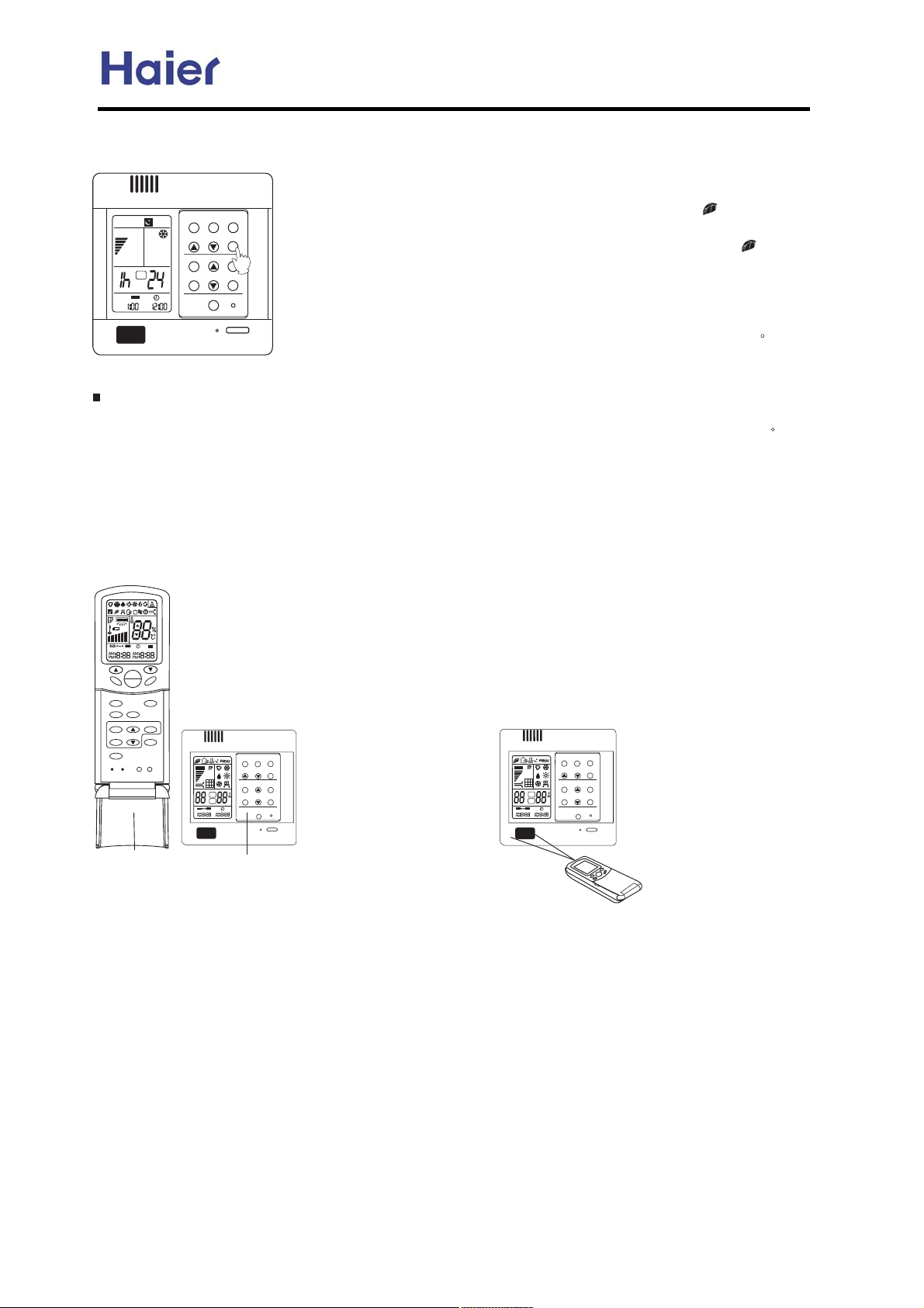
Commercial Air Conditioner Model: AU242FHBIA,
AU482FIBIA, AU48NFIBJA
K^jon da]gnd boi_neji
QNc-5 2- 31x 2{x {xt*2{y3,v2|-, I-,*7 y-0 3,|21 5|2{ 2{|1 y3,v2|-,J
\y2x01x22{x 0|z{2 y3,v2|-, +-wxL .0x11 {xt*2{u322-,L
a\i
mqdib
hj_`
c`\gnc
n`hk
^gj^f m`n
m`n
jaa
\h
\h
;
ndh`l mg``k
adgn`l l`m`n
l`m`n
jiOjaa
0x+-2xv-,20-**x0-05|0xv-,20-**x0 w|1.*t71 G
-0 ,xzt2|4x|-, zx,x0t2-0 12t021 3. 2- t..*7 -67zx,-0,xzt2|4x
|-, 2- |,w--0 3,|2N k0x11 2{x u322-, tzt|,L2{x 1|z, G
xt0xw t,w ,xzt2|4x|-, zx,x0t2-0 12-.1 5-0~|,zN \y2x0 t** {xt*2{
y3,v2|-, -y 2{x |,w--0 3,|2 ux|,zy3**7 vt,vx*xwL -67zx, .3+.
12-..xwN
^\ondjiZ
q{x,2{x 2x+.x0t230x -y 2{x -32w--0 3,|2 |1 *-5x02{t, TL
-67zx, .3+. |1 t32-+t2|vt**7 12-..xwL |y .0x11 {xt*2{u322-,
}312 2{x,L -67zx, .3+. v-3*w ,-2 12t02 3.N ]32 |y 2{x t|0 v-,w|M
j,2{x Gcxt*2{G +-wxL |y 7-3 5t,2
2- 1x22|,z 2|+|,z -.x,+-wxL 1{-3*w
v*-1x 2{x {xt*2{y|012Z j,2{x 2|+|,z
-.x,+-wxL .*xt1xw-,H231x {xt*2{
y3,v2|-,N
2|-,x0 {t12{x ,xzt2|4x|-, y3,v2|-, 1|+3*2t,x
2{x {xt*2{u322-,L ,xzt2|4x|-, y3,v2|-, v-3*w 12|** ux -.x0t2xwN
q{x,2{x 2x+.x0t230x -y 2{x -32w--0 3,|2 |1 {|z{x02{t, VL
-67zx, .3+. v-3*wt32-+t2|vt**7 0x13+x 2- -67zx,M+t~x
y3,v2|-,N
a-0 cMhlp 5|0xw 27.x|,w--0 3,|2L 2{x 5|0xw v-,20-**x0 vt, ux +t2v{xw 5|2{ 2{x 0x+-2xv-,20-**x0
slMcWQ 2- 0xt*|8x 2{x 0x+-2xv-,20-* y3,v2|-,N
GL-67zx, .3+.
G w|1t..M
B
-31L5{x,.0x11
B
gxy2.|v230x|1 t 5|0xw 0x+-2xv-,20-**x0L 5{|v{ vt, ux 31xw -,
3,|21 Ln{x 0x+-2xv-,20-**x0 vt, ux .30v{t1xw x620t**7N
]
\
q|0xw 0x+-2x^-,20-**x031|,z +x2{-wZ
QNo1x -,x 5|0xw 0x+-2xv-,20-**x0N mxx y|z IQJ
K
[
Z
V
VPP
h_
n`hk
ji
jaa
mqdib
a\i
hj_`
mg``k
al`mc
c`\gnc
m`n
^gj^f
cdbcOmj
ndh`l
adgn`l
gj^f
gdbcn
l`m`n
^j_`
lx+-2xv-,20-***x0
lx+-2xv-,20-***x0 |1 t, tvvx11-07L 2- ux -0wx0xw x620t**7
RN\*1- vt, u37 t 0x+-2xv-,20-**x0 x620t**7L 0xt*|8x
5|0xw 0x+-2
xv-,20-* K 0x+-2xv-,20-* w3t* v-,20-* +-wx1N
FC\dai nda lahjna _jinljggal _]i ^a oma` ji maleam pela` lahjna _jinljggal
oienm Bnd]i kga]ma klamm nda ^jnnji ?MVNO?nj _djjma nda kljcl]h jb _j`a
?K?
mqdib
a\i
hj_`
\onj
m`n
ljjh
<
ji
jaa
q|0x 0x+-2xv-,20-***x0
^
n`hk
^gj^f m`n
ndh`l mg``k
adgn`ll`m`n
jiOjaa
c`\gnc
l`m`n
mx0|x1
mqdib
a\i
hj_`
\onj
m`n
ljjh
<
ji
jaa
^
n`hk
^gj^f m`n
ndh`l mg``k
adgn`ll`m`n
jiOjaa
c`\gnc
l`m`n
5|0xw v-,20-*
-62-
Page 63
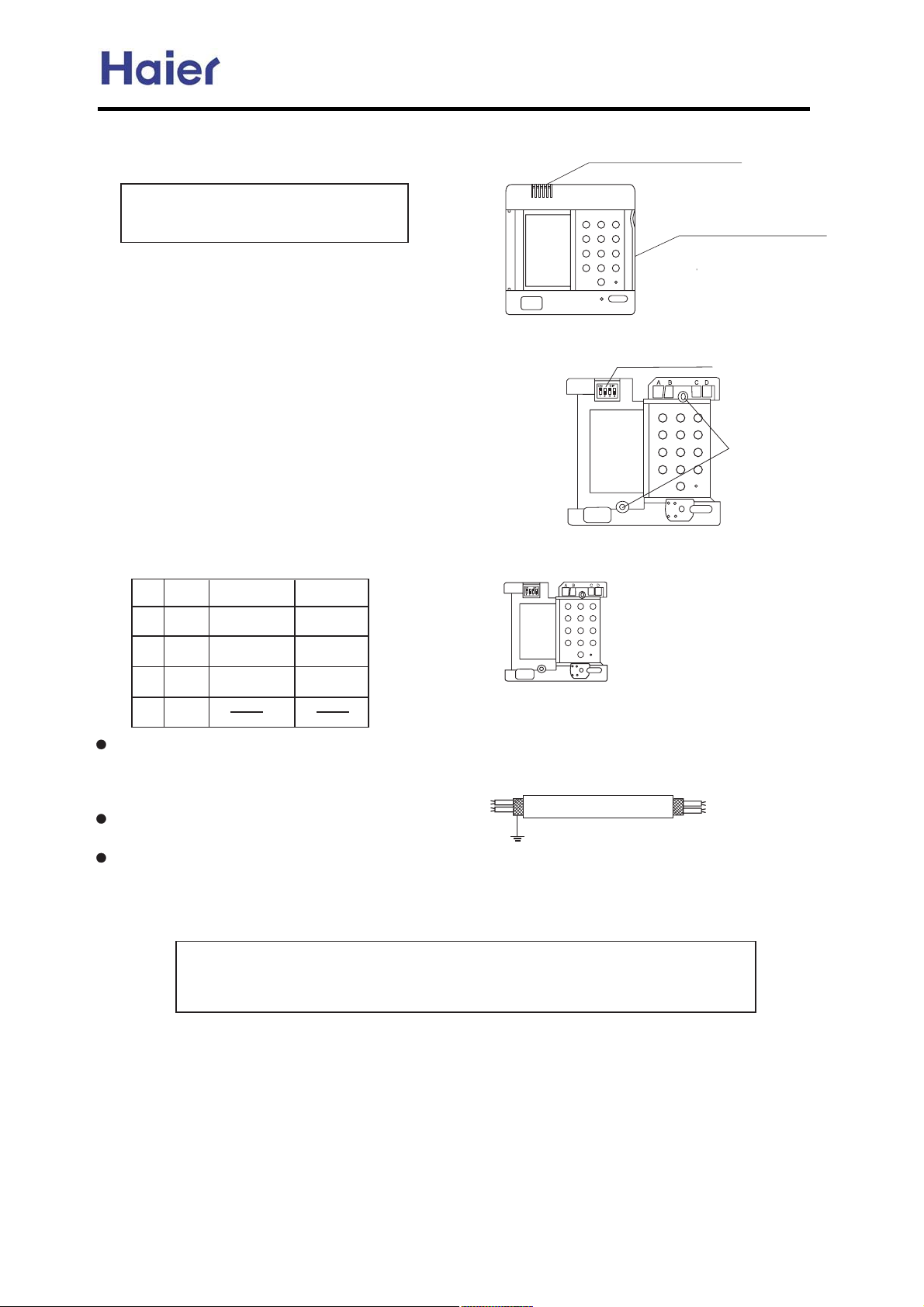
Commercial Air Conditioner Model: AU242FHBIA,
AU482FIBIA, AU48NFIBJA
QN lx+-4x 3..x0 v-4x0-y 5|0xv-,20-**x0
lx+-4x 3..x0.t02 -y 5|0xv-,20-**x0 u7.0x11N
k^] |1 +-3,2xw -, *-5x0.t02 -y 5|0x
v-,20-**x0L ux vt0xy3* ,-2 2- wt+tzx |2N
RN d,12t** 2{x 5|0xw 0x+-2xv-,20-**x0
k*xt1xw0|** 25- {-*x1-,2{x 5t** tvv-0w|,z 2- 2{x
utv~ v-4x01v0x5 {-*x .-1|2|-, -y 2{x 5|0x 0x+-2x
v-,20-**x0L 2{x, 120|~x 2{x 5--wu*-v~ 2- 2{x {-*x1
0x1.xv2|4x*7L 2{x, t*|z,2{x R 1v0x5 {-*x -y 2{x
5|0x
v-,20-**x0 utv~ v-4x02-2{x 5--wu*-v~L yt12x,
2{x 5|0x 0x-2xv-,20-**x02-2{x 5t** 31x 5--w
1v0x51N
SN m5|2v{ 1x22|,z
n{x 15|2v{11x22|,zt1 y-**-51ZQNji RNjaa SNji TNjaa
Ujna
n07 t1 yt0 t1 .-11|u*xty*t2 130ytvx y-0 |,12t**t2|-,N
_-,H231xx6vx11|4xy-0vx 5{x,2|z{2x,|,z 1v0x51L
-0 *-5x0.t02 +|z{2 z-2 wxy-0+xwN
TN ^-,,xv2|,z +x2{-wt12{x y-**-5|,z v{t02
o..x0 v-4x0-y 5|0x
v-,20-**x0
g-5x0 v-4x0-y 5|0x
v-,20-**x0
m5|2v{ u322-,
mv0x5 {-*x
55
v-,2x,21
QRp
b,w
^jh
i-
Q
R
S
T
m7+u-*
\
]
^
_
v-*-30
q{|2x -0 b0xx,
lxw
sx**-5
o1x 1{|x*xwx 5|0x1 y-0 2x*xv-++3,|vt2|-,
ux25xx,5|0xv-,20-**x0 t,w|,w--0 3,|2[
|,w--0 3,|2 t,w -32w--0 3,|2N b0-3,w 2{x
1{|x*w -, -,x 1|wxN
j2{x05|1x +|1-.x0t2|-, uxvt31x -y ,-|1x
+t7-vv30N
m|z,t*5|0x|11x*yM.0-4|wxw u731x0N
UN lx.*tvx 2{x 3..x0 v-4x0-y 5|0xv-,20-**x0
]x vt0xy3* ,-2 2- {-*ww-5, 2{x 5|0|,zN
Qein
QN k-5x0 13..*7 15|2v{ t,w 1|z,t*5|0x 1{-3*wux.0x.t|0xw u72{x 31x0N
RN _-,H2 2-3v{ k^] 5|2{{t,wN
]tv~ v-4x0-y 2{x 5|0x
v-,20-**x0
m{|x*wxw 5|0x
z0-3,w
-63-
Page 64
7OR ]tmwhwlk jutywurrlw gbN\TQ
Commercial Air Conditioner Model: AU242FHBIA,
AU482FIBIA, AU48NFIBJA
{:3/A3 >@3AA B63 0=BB=< VnzopV B= 16==A3 B63 >@=5@/; =4 1=23 VmV^
~63@3 6/D3 A=;3 4C<1B7=< 0CBB=<A
7< B63 s]x|+AGAB3; C<7BA B6/B B63G /@3 <=B CA3^~63 23B/7:32 7<4=@;/B7=<7A/A4=::=Ej
Viuzy \lhryo mztjyutU
~63@3 7A Vyprl~t+p tzyV 4C<1B7=< =< B63 ,lww xz*y~po BG>3 /<2 nlmtyp~ BG>3 7<2==@ C<7BA\B63
23B/7:32 7<4=@;/B7=< =4 B67A 4C<1B7=< >:3/A3 A33
the following.
~63@3 7A Vz-.rpy rpyp|l~tyrV 4C<1B7=< =< B67A s]x|+ AGAB3; Y7BXA=4 /< =>B7=</: >/@B AGAB3;Z^~63
AGAB3; 1/<53<3@/B3 4@3A6 =FG53< B= B63 @==; A>/13 0G 7<AB/::7<5 B67A >/@B AGAB3;^
l0=CB s3/:B6 4C<1B=<Yt4 B63 C<7B 6/A B63 4C<1B7=< =4 0=B6 Vyprl~t+p tzyV /<2 Vz-.rpy rpyp|l~tyrVZ
l4B3@ A3B B63 @756B 4C<1B7=<;=23\>@3AA 63/:B6 0CBB=<\@3;=B3 1=<B@=::3@ 27A>:/GA VV\<=E B63 7<2==@ C<7B
>=E3@ :/;> BC@<A 4=@; =@/<531=:=@ B= 5@33< 1=:=@\=FG53< >C;>=@<35/B7D3 7=<53<3@/B=@ AB/@BA C> B=
/>>:G =FG53< =@ <35/B7D3
{@3AA B63 0CBB=< /5/7<\B63 A75<V
7=< B= 7<2==@^
V27A/>>3/@32 /<2 <35/B7D3 7=<53<3@/B=@ AB=>A E=@97<5^/4B3@ /:: 63/:B6
4C<1B7=< =4 B63 7<2==@ C<7B037<5 4C::G1/<13:32\=FG53< >C;> AB=>>32^
l0=CB s3/:B6 4C<1B=<Y=<:G 6/A =FG53< >C;> 4/<1B=<Zj
l4B3@ A3B B63 @756B 4C<1B7=<;=23\>@3AA 63/:B6 0CBB=<\@3;=B3 1=<B@=::3@ 27A>:/GA V
V\<=E B63 7<2==@ C<7B
>=E3@ :/;> BC@<A 4=@; =@/<531=:=@ B= 5@33< 1=:=@\=FG53< >C;> 53<3@/B=@ AB/@BA C> B= />>:G =FG53< B=
7<2==@^
{@3AA B63 0CBB=< /5/7<\B63 A75<V
V27A/>>3/@32 ^/4B3@ /:: 63/:B6 4C<1B7=< =4 B63 7<2==@ C<7B037<5 4C::G
1/<13:32\=FG53< >C;> AB=>>32^
`adZU[uw yol ptkuuw fhrr _uztylk htk Xhiptly ztpyx
}=;3 4C<1B7=<A=4 B67A1=<B@=::3@ ;/G03 <=B /D/7:/0:3 /11=@27<5 B= B63 1=@@3A>=<27<5 {nmXA
4C<1B7=<A\AC16 /A E6716 /@3 =>B7=</:4=@ 27443@3<BC<7B^
af bh cabiadaa ag ba bdbc cb cch
`adZU[uw yol Xut{lwypirl htk Xhxxlyyl htk jutxurl ptkuuw ztpyx
}=;3 4C<1B7=<A=4 B67A1=<B@=::3@ ;/G03 <=B /D/7:/0:3 /11=@27<5 B= B63 1=@@3A>=<27<5 {nmXA
4C<1B7=<A\AC16 /A E6716 /@3 =>B7=</:4=@ 27443@3<BC<7B^
e af bh cabiadaa ag ba bdbc cb cch
`adZU[uw yol Yzjy htk Xlprptn jutjlhrlk ptkuuw ztpyx
}=;3 4C<1B7=<A=4 B67A1=<B@=::3@ ;/G03 <=B /D/7:/0:3 /11=@27<5 B= B63 1=@@3A>=<27<5 {nmXA
4C<1B7=<A\AC16 /A E6716 /@3 =>B7=</:4=@ 27443@3<BC<7B^
e af bh cabiadaa ag ba bdbc cb cchb
-64-
Page 65
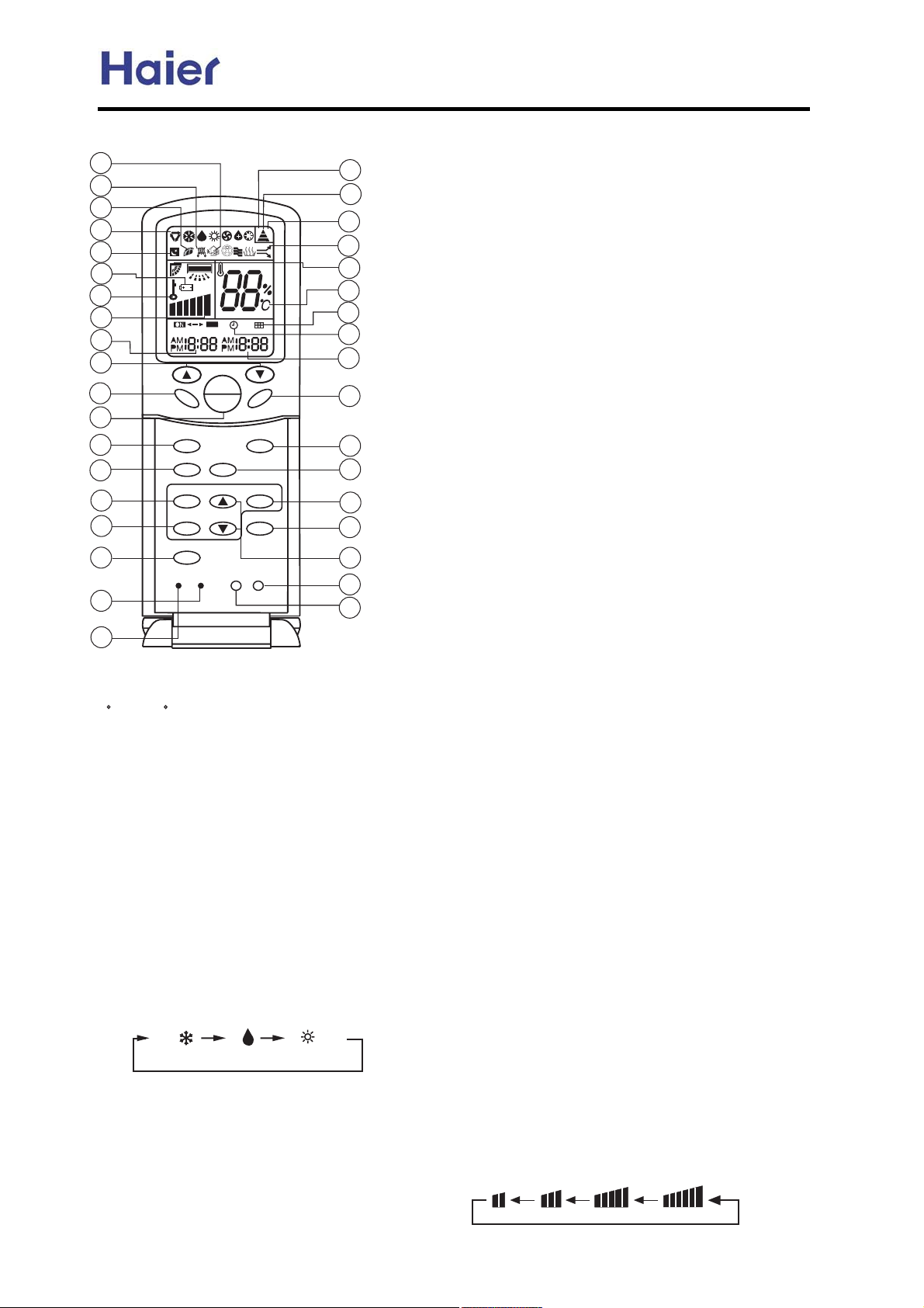
Commercial Air Conditioner Model: AU242FHBIA,
AU482FIBIA, AU48NFIBJA
|3;=B3 1=<B@=::3@
bh
bi
c`
ca
cb
cc
cd
ce
cf
a`
m
l
V
e
d
a
a[[
a
b
c
d
e
f
g
h
i
},tyr
xzop
splw~s
nwznv
~txp|
qtw~p|
|p}p~
nzop
~px{
zy
zqq
q|p}s
wtrs~
qly
}wpp{
}p~
strs_}z
wznv
bg
bf
be
bd
bc
bb
ba
b`
ai
ah
ag
af
ae
ad
ac
ab
aa
a^~px{ }3BB7<5 mCBB=<
Y*A32 B= A3B B3;>3@/BC@3^ }3BB7<5 @/<53Aj
af n B= c` nZ
b^},tyr mCBB=<
t4 G=C >@3AA B67A 0CBB=< =<13\ /CB= AE7<5 E7:: 03
/1B7D/B32^
t4 G=C >@3AA B67A 0CBB=< /5/7<\ B63 :=CD3@ E7:: 47F
7< B63 >@3A3<B >=A7B7=<^
c^{=E3@ zy_zqq mCBB=<
*A32 4
=@ C<7B AB/@B /<2 AB=>
l4B3@ >=E3@ =<\ B63 wno =4 @3;=B3 1=<B@=::3@ E7::
27A>:/G B63 >@3D7=CA =>3@/B7=< AB/B3 Y3F13>B 4=@
~txp|\}wpp{ /<2 },tyr AB/B3Z^
d^z>3@/B7=< xzop
*A32 B= A3:31B =>3@/B7=<;=23^
pD3@G B7;3 G=C >@3AA xzop 0CBB=<\ =>3@/B7=<
;=23 16/<53A /11=@27<5 B= 4=::=E7<5 A3?C3<13j
dol mztjyput um jukl W
nzzw
o|.
spl~
e^splw~s mCBB=<
f^nwznv mCBB=<
*A32 B= A3B 1=@@31B B7;3^
g^~txp| mCBB=<
*A32 B= A3:31B ~txp| ;=23j~txp| zy\~txp|
zqq^
Yy=B3j 74 B7;3=4 ~txp| zy 7A B63 A/;3/A~txp|
zqqZ
h^ qtw~p| mCBB=<
*A32 B= A3B C>_2=E<4C<1B7=< =4 47:B3@^
i^nzop mCBB=<
*A32 B= A3:31B n=23 l =@ m\ B67A ;/<C/:7A 4=@ 1=23 m^
a`^|p}p~ mCBB=<
{@3AA B67A 0CBB=< 0G CA7<5 / A6/@> /@B71:3 B= @3AC;3 B63
1=@@31B =>3@/B7=< =4 B63 @3;=B3 1=<B@=::3@ 7< 1/A3
=4<332\ 7^3^ 4=@ 3F/
;>:3 7< 1/A3 =4;/:4C<1B7=<A
2C3 B= 3:31B@=;/5<3B7127ABC@0/<13^
aa^wtrs~ mCBB=<
*A32 B= :756B B63 1=<B@=: >/<3: Y=<:G 4=@ 1/07<3B C<7BZ
ab^wznv mCBB=<
*A32 B= :=19 =>3@/B7=< 0CBB=< /<2 wno 27A>:/G 1=<B3<BAj
0G >@3AA7<5 B67A 0CBB=<\ =B63@ 0CBB=<A1=;3A =CB =4
4C<1B7=< /<2 :=19 AB/B3 27A>:/G />>3/@Ak 74 G=C >@3AA
7B/5/7<\ :=19 AB/B3 E7:: 03 <= ;=@3 /1B7
D3 /<2 :=19 AB/B3
27A>:/G E7:: 27A/>>3/@^
ac^sz*|l28CAB;3<B
*A32 B= A3B 1:=19 /<2B7;3@ A3BB7<5
ad^strs_}z mCBB=<
*A32 B= A3:31B strs =@ }zq~ =>3@/B7=<^
ae^}p~ mCBB=<
*A32 B= 1=<47@; ~txp| /<2 nwznv A3BB7<5A E63<
=@ 1==:7<5_63/B7<5
af^q|p}s mCBB=<
*A32 B= A3B 4@3A6 ;=23\ B63 C<7BE7:: 2@/E 7< 4@3A6 /7@^
ag^}wpp{ mCBB=<
Y~63 1:=19 ;CAB 03 1=@@31B32 034=@3 A3BB7<5 A:33> 4C<1B7=<Z
*A32 B= A3B A:33> ;=23^
ah^qly mCBB=<
*A32 B= A3:31B 4/< A>332jwz,\xto\strs\l*~z^
ai^~txp| zqq o7A>:/G
b`^~txp| o7A>:/G
ba^qtw~p| o7A>:/G
,63< B63 47:B3@ <332 03 1:3/<32\ B63 A75< E7::
/>>3/@ /CB=;/B71/::G^
bb^~px{p|l~*|p o7A>:/G
bc^l*~z },tyr o7
A>:/G
bd^stry_}z|C< o7A>:/G
be^n=23 l 27A>:/G
bf^}trylw }pyotyr o7A>:/G
bg^n=23 m 27A>:/G
bh^q@3A6 o7A>:/G
bi^lCF7:7/@G pwpn~|tnlw spl~tyr o7A>:/G
c`^splw~s o7A>:/G
o7A>:/GA E63< 63/:B6G @C<4C<1B7=<7A A3B^
ca^z>3@/B7=< xzop o7A>:/G
cb^}wpp{ }B/B3 o7A>:/G
cc^ml~~p|. p<3@5G o7A>:/G
y=B74G B63 CA3@ E63<7B 7AB7;3B=16/<53 B63 0/BB3@73A^
cd^wznv }B/B3 o7A>:/G
ce^qly }{ppoo7A>:/G
V
e
d
wz,
xto
strs l*~z
a
-65-
Page 66
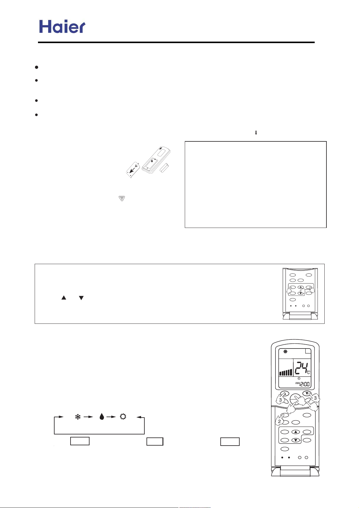
Commercial Air Conditioner Model: AU242FHBIA,
AU482FIBIA, AU48NFIBJA
cf^~txp| zy o7A>:/G
|3;=B3 n=<B@=::3@ z>3@/B7=<
,63<7<CA3\ 27@31B A75</: B@/<A;7AA7=< 63/2 B=
B63 @3137D3@ >:/132 =< B63 7<2==@ C<7B
~63 27AB/<13 03BE33< B63 @3;=B3 1=<B@=::3@ /<2
B63 @3137D3@ A6=C:203;/F g; /<2 B63@3 A6=C:2
03 <= =0AB/1:3 03BE33< B63;^
o= <=B B6@=E B63 @3;=B3 1=<B@=::3@k >@3D3<B 7B
4@=; 037<5 2/;/532^
,63< =>3@/B7<5 B63 @3;=B3 1=<B@=::3@ 7< /< /@3/
E63@3 3:31B@=<71/::G1=<B@=::32 :756BA /@3 7<AB/::32
=@ E7@3:3AA 6/<2A3BA /@3 CA32\ >:3/A3 ;=D3 1:=A3@
B= B63 7<2==@ C<7B/AB634C<1B7=< =4 B63 @3;=B3
1=<B@=::3@ ;756B 03 /4431B32 0G A75</:A3;7BB32 0G
B63 /0=D3 ;3<B7=<32 3?C7>;3<BA^
m/BB3@G :=/27<5
m/BB3@G :=/27<5
+-
-+
m/BB3@73A /@3 47BB32 /A 4=::=EAj
|3;=D3 B63 0/BB3@G 1=;>/@B;3<B
:72 }:756B:G >@3AA /<227A3<5/53 B63 0/BB3@G
1=;>/@B;3<B :72 ;/@932 E7B6 V
V /<2 B63< 6=:2 B63
@3;=B3 1=<B@=::3@ 0G B63 C>>3@ A31B7=< /<2 B63< @3;=D3
B63 0/BB3@G 1=;>/@B;3<B :72 0G >@3AA7<5 7< B63 27@31B7=<
=4 B63 /@@=E /A A6=E<7<B63 475C@3 /0=D3^
^uhkptn yol ihyylw}
p<AC@3 B6/B 0/BB3@73A /@3 1=@@31B:G>:/132 7< B63
1=;>/@B;3<B /A @3?C7@32 4=@ >=A7B7D3 /<2 <35/B7D3
B3@;7</:A^
blvrhjptn yol ihyylw} jusvhwyslty rpk
~63 0/BB3@G 1=;>/@B;3<B :72 7A@37<AB/::32 7< B63 @3D3@A3
A3?C3<13^
Ypxvrh} wl{pl|
{@3AA B63 0CBB=< B= A33 74 0/BB3@73A /@3 >@=>3@:G 47BB32^
t4<=27A>:/G />>3/@A\ @347B B63 0/BB3@73A^
Xutmpwshyput ptkpjhyuw
t4<= 7<271/B7=<7A27A>:/G32 /4B3@ >@3AA zy_zqq
0CBB=<\ @3:=/2 B63 0/BB3@73A^
t4 B63 @3;=B3 1=<B@=::3@ 2=3A <=B =>3@/B3 /A 23A75<32
/4B3@ 47BB7<5 <3E 0/BB3@73A =4 B63 A/;3 BG>3\ >@3AA
B63 |3A3B 0CBB=< Y;/@932 Z E7B6/>=7<B32 /@B71:3^
y=B3j
tB 7A @31=;;3<232 B6/B B63 0/BB3@73A 03 @3;=D32
4@=; B63 1=;>/@B;3<B 74 B63 @3;=B3 1=<B@=::3@ 7A <=B
CA32 4=@ /< 3FB3<232 >3@7=2^
~63 @3;=B3 1=<B@=::3@ 7A >@=5@/;;32 4=@ /CB=;/B71
B3AB =4 =>3@/B7=<;=23 /4B3@ B63 0/BB3@73A /@3 @3>:/132^
,63< B63 B3AB 7A1=<2C1B32\ /:: 71=<AE7:: />>3/@ =<
B63 A1@33< /<2 B63< 2
>@=>3@:G 47BB32^
,63< B63 27A>:/G 031=;3 E3/9\B67A27A>:/G <=
>=E3@ 7< B63 0/BB3@G
7A/>>3/@ 74 B63 0/BB3@73A /@3
\
>:3/A3 16/<53 B63 0/BB3@G
^
Xrujq cly
,63< C<7B 7A AB/@B32 4=@ B63 47@AB B7;3/<2/4B3@ @3>:/17<5 0/BB3@73A 7< @3;=B3 1=<B@=::3@\
1:=19 A6=C:203/28CAB32 /A 4=::=EAj
a^{@3AA nwznv 0CBB=<\ 1:=19 7<271/B7=< =4 V lx V =@ V {x V 4:/A63A^
b^{@3AA =@ B= A3B 1=@@31B B7;3^p/16 >@3AA E7:: 7<1@3/A3 =@ 231@3/A3 a ;7<^t4
B63 0CBB=<7A 93>B >@3AA32\ B7;3E7:: 7<1@3/A3 =@ 231@3/A3 ?C719:
G^
c^l4B3@ B7;3 A3BB7<5 7A1=<47@;32\ >@3AA V}p~V jlx =@ {x AB=> 4:/A67<5\ E67:31:=19
AB/@BA E=@97<5^y=B3jlx ;3/<A ;=@<7<5 /<2 {x ;3/<A/4B3@<==<^
Xaa^ M \ZVd htk Ybg avlwhyput
a^ *<7B AB/@B
{@3AA zy_zqq 0CBB=<\C<7B AB/@BA^
{@3D7=CA =>3@/B7=< AB/BCA />>3/@A =< wno Y3F13>B 4=@ ~txp|\ }wpp{ /<2
},tyr A3BB7<5Z
b^}3:31B =>3@/B7=<;=23
{@3AA xzop 0CBB=<^lB 3/16 >@3AA\ =>3@/B7=<;=23 16/<53A /A 4=::=EAj
4=::=EAj
nzzw
~63< A3:31B =>3@/B7=< =@ A3:31B =>3@/B7=< =@ A3:31B =>3@/B7=<
nzzw
o|.
spl~
o|.
spl~
},tyr
|p}p~
xzop
splw~s
nwznv
~txp|
qtw~p|
}wpp{xzop
q|p}s
splw~s
nwznv
}p~
1
strs_}z
~txp|
0
/
qtw~p|
wznv
wtrs~
|p}p~
nzop
m
V
e
d
a
~px{
zy
/
zqq
qly
wtrs~
}wpp{
}p~
strs_}z
wznv
2
3
q|p}s
nzop
-66-
Page 67
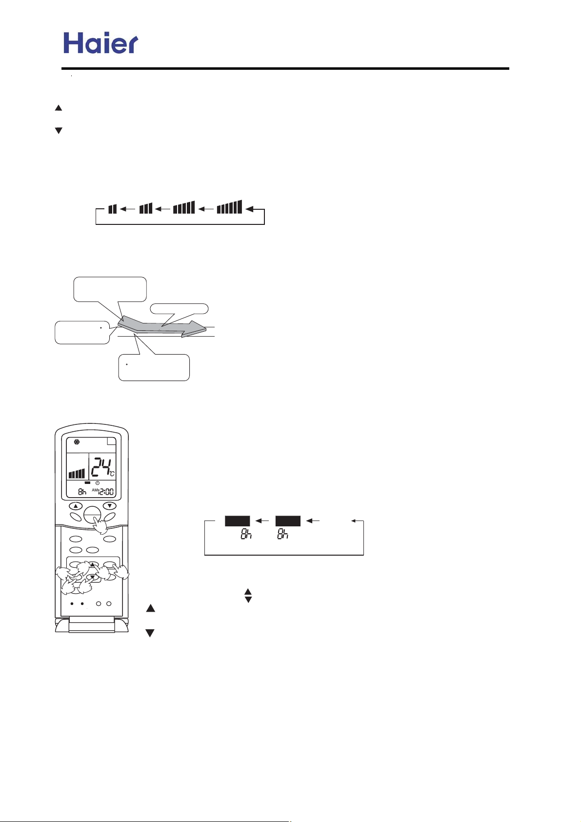
Commercial Air Conditioner Model: AU242FHBIA,
AU482FIBIA, AU48NFIBJA
c^~3;>3@/BC@3 A3BB7<5
{@3AA ~px{ 0CBB=<^
pD3@G B7;3 B63 0CBB=<7A >@3AA32\ B3;>^ A3BB7<5 7<1@3/A3A a235@33^t4 0CBB=<7A 93>B 23>@3AA32\ B3;>^
A3BB7<5 E7:: 7<1@3/A3 ?C719:G^
pD3@G B7;3 B63 0CBB=<7A >@3AA32\ B3;>^ A3BB7<5 231@3/A3A a235@33^t4 0CBB=<7A 93>B 23>@3AA32\ B3;>^
A3BB7<5 E7:: 231@3/A3 ?C719:G^
}3B >@=>3@ B3;>3@/BC@3
d^l28CAB qly 0CBB=<
{@3AA qly 0CBB=<^lB 3/16 >@3AA\ 4/< A>332 16/<53A /A 4=::=EAj
V
e
d
wz,
xto
strs l*~z
l7@1=<27B7=<3@ E7:: @C< /B B63 A3:31B32 4/< A>332
e^ *<7B AB=>
{@3AA zy_zqq 0CBB=<\ C<7B AB=>A
nzzw =>3@/B7=< AB/@BA
E63< @==; B3;>^7A
67563@ B6/< B3;>^A3BB7<5^
*:B@/]:=E /7@ 4:=E
~3;>^ A3BB7<5 [b n
a
^
t< spl~ ;=23\E/@; /7@E7:: 0:=E =CB /4B3@ / A6=@B >3@7=2 =4 B7;3
2C3 B= /<B7]1=:2 4C<1B7=<^
z< @3/167<5 B3;>^ A3BB7<5
[b n\ C<7BE7:: @C<7<;7:2
o|. ;=23^
dpslw a`Pa[[ [ztjyputMKcly jrujq juwwljyr} ilmuwl xyhwyptn d]_Zb uvlwhyputL
dpslw a`Na[[ [ztjyput
m
a[[
~px{
zy
zqq
qtw
q|p}s
|
wtrs~
qly
/
}wpp{
}p~
strs_}z
str
1
wznv
0
|
} ,tyr
5
|p}p~
xzop
splw~s
nwznv
~txp|
qtw~p|
2
3
nzop
d^~7;3@ 1=<47@;7<5
l4B3@ B7;3 A3BB7<5 \>@3AA }p~ 0CBB=< B= 1=<47@
e^n/<3: ~txp| ;=23
uCAB >@3AA ~txp| 0CBB=< A3D3@/: B7;3A C<B7: ~txp| ;=23 27A/>>3/@A^l11=@27<5 B= B63 B7;3
A3BB7<5 A3?C3<13=4 ~txp| zy /<2 ~txp| zqq\ 37B63@ AB/@B]AB=>A =@ AB=>A]AB/@B 1/< 03 @3/:7H32^
a^*<7B AB/@B
l4B3@ C<7B AB/@BA\A3:31B G=C@ 23A7@32 =>3@/B7=<;=23Yz>3@/B7=<;=23
E7:: 03 27A>:/G32 =< wnoZ
b^~txp| ;=23 A3:31B7=<
{@3AA ~txp| 0CBB=< =< B63 @3;=B3 1=<B@=::3@ B= 16/<53~txp| ;=23^
pD3@G B7;3 B63 0CBB=<7A >@3AA32\27A>:/G =4 ~txp| ;=23 16/<53A /A
4=::=EAj
~63< A3:31B ~txp| ;=23 /A <33232
4
c^~7;
3 A3BB7<5
+* +~~
~txp| zy
~txp| zqq
0:/<9
{@3AA B7;3 0CBB=<
pD3@G B7;3 B63 0CBB=<7A >@3AA32\B7;3 7<1@3/A3A /< 6=C@^t4 B63 0CBB=<
7A 93>B >@3AA32\B7;3E7:: 16/<53A ?C719:G^
pD3@G B7;3 B63 0CBB=<7A >@3AA32\B7;3 231@3/A3A /< 6=C@^t4 B63 0CBB=<
7A 93>B >@3AA32\B7;3E7:: 16/<53A ?C719:G^tB1/< 03 /28CAB32 E7B6 7<
ab 6=C@A /B E7::^lx @343@A B= ;=@<7<5 /<2 {x @343@A B= /4B3@<==<
; B7;3^
^
l4B3@ @3>:/17<5 0/BB3@73A =@ 74 />=E3@ 4/7:C@3 =11C@A\~txp| A3BB7<5 ;CAB 03 @3A3B^
|3;=B3 1=<B@=::3@ 6/A ;3;=@G 4C<1B7=<^,63< G=C CA3 ~txp| ;=23 <3FB B7;3\8CAB >@3AA }p~
0CBB=< /4B3@ ;=23 A3:31B7=<74B7;3@ A3BB7<5 7A B63 A/;3 /A B63 >@3D7=CA =<3^
-67-
Page 68
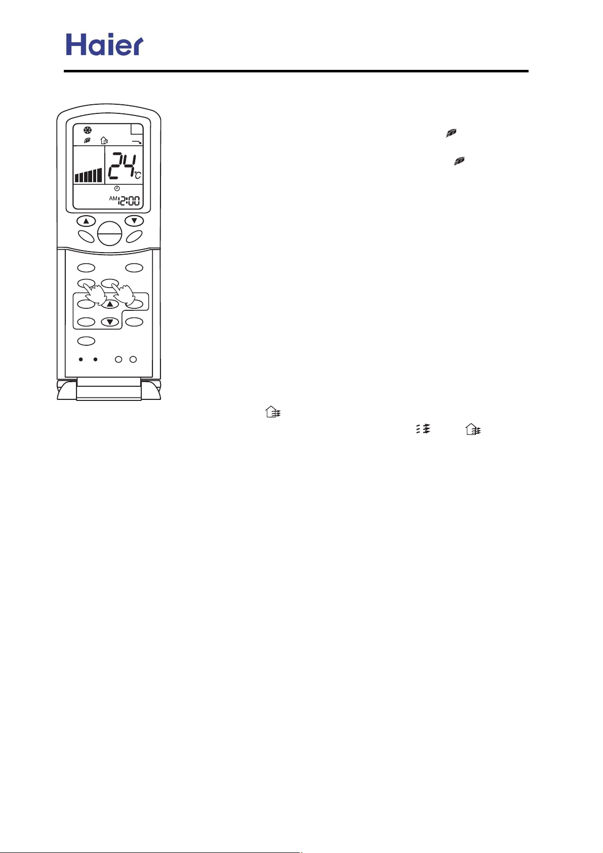
\lhryo J [wlxo Vpw uvlwhyput
\lhryo uvlwhyput
Commercial Air Conditioner Model: AU242FHBIA,
AU482FIBIA, AU48NFIBJA
},tyr
|p}p~
xzop
splw~s
nwznv
~txp|
qtw~p|
nzop
V
e
d
a
~px{
zy
zqq
q|p}s
wtrs~
0/
m
}wpp{
}p~
strs_}z
wznv
qly
l4B3@ BC@<7<5 =< B63 C<7B/<2 A3B B63 23A7@32 E=@97<5 ;=23^
{@3AA B63 s3/:B6 0CBB=<\B63 wno E7:: 27A>:/GV
V\B63 C<7B
0357<A 63/:B6 =>3@/B7=<YAB/@B B63 <35/B7D3 7=<53<3@/B7=<
23D713Z^{@3AA B63 s3/:B6 0CBB=< /5/7<\B63 V
V27A>:/G32
=< B63 wno 27A/>>3/@A\63/:B6 =>3@/B7=<7A1/<13::32YBC@<
=44 B63 <35/B7D3 7=<53<3@/B7=< 23D713Z^
y=B3j,63<7<2==@ 4/<;=B=@ 2=3A <=B E=@9\B63 C<7BE7:: /CB=;
/B71/::G BC@< =44 <35/B7D3 7=<53<3@/B7 =< 23D713^
Viuzy \lhryo uvlwhyput
l4B3@ B63 AB/@B =
4 63/:B6 =>3@/B7=<\B63 <35/B7D3 7=<53<3@/B=@
E7:: 53< 3@/B3 :/@53/;=C<B=4<35/B7 D3 7=<\E67161/<
34431B7D3:G0/:/<13 B63 /;=C<B=4 >=A7B7D3W <35/B7D3 7=<7<
B63 /7@/<2 6/A B63 0/1B3@7/]97::7<5 /<2/113:3@/B7<5 B63 2CAB
23>=A7B7=
< =4 B63 @==; B= ;/93B63 @==; /7@ 4@3A6 /<2 63/:B6G^
q@3A6 l7@ =>3@/B7=<
l4B3@ BC@<7<5 =< B63 C<7B/<2 A3B B63 23A7@32 E=@97<5
;=23YB63 @3;=B3 1=<B@=::3@ wno /<21=<B@=: >/<3: wno
27A>:/G B63 E=@97<5 ;=23Z^
{@3AA B63 q@3A6 /7@ 0CBB=< =4 B63 @3;=B3 1=<B@=::3@\B63 wno
27A>:/GAV
V\/<2 B63 C<7B0357<A1=<B7<C=CA 4@3A6 /7@
=>3@/B7=<k>@3AA B63 0CBB=< /5/7<\B63V
V7< V
V4:/A63A
/<20357< /CB=;/B71 4@3A6 /7@ =>3@/B7=<^>@3AA B63 0CBB=<4=@
B63 B67@2 B7;3B=1/<13:4@3A6 /7@ 4C<1B7=<^
n=<B7<C=CA 4@3A6 /7@ =>3@/B7=<j~6/B 7AB=A/G\74 B63@3 7A <=
7<B3@D3<B7=<\B63 4@3A6 /7@ =>3@/B7=< E7:: 1=<B7<C=CA:G@C< /<2
<=B AB=>^
lCB=;
/B71 4@3A6 /7@ =>3@/B7= <j~6/B 7AB=A/G\B63 4@3A6 /7@
=>3@/B7=< @C<A 7<B3@;7BB3<B:G^l4B3@ b` ;7<CB3A =>3@/B7=<\B63
4@3A6 /7@ =>3@/B7=< E7:: AB=> 4=@ b` ;7<CB3Ak@C<A 4=@ /<=B63@
b` ;7<CB3A\7BE7:: AB=> 4=@ /<=B63@ b` ;7<CB3A\@3>3/B32:G@C<A^
y=B3jp7B63@
7< zy =@ zqq AB/B3\B63 4@3A6 /7@ =>3@/B7=< 1/<
03 7<23>3<23<B:G A3B B= @C<^
Viuzy [wlxo hpw uvlwhyput
~63 D3<B7:/B7=< 23D713=4 B67A/7@1=<27B7=<3@ 1/< 27A16/@53 B63 7<2==@ /7@ B= =CB2==@A\E67:3 B63
=CB2==@ 4@3A6 /7@ AC>>:3;3<BB=7<2==@A\A= B6/B 4C:47::A B63 4@3A6 /7@ 4C<1B7=<^
-68-
Page 69
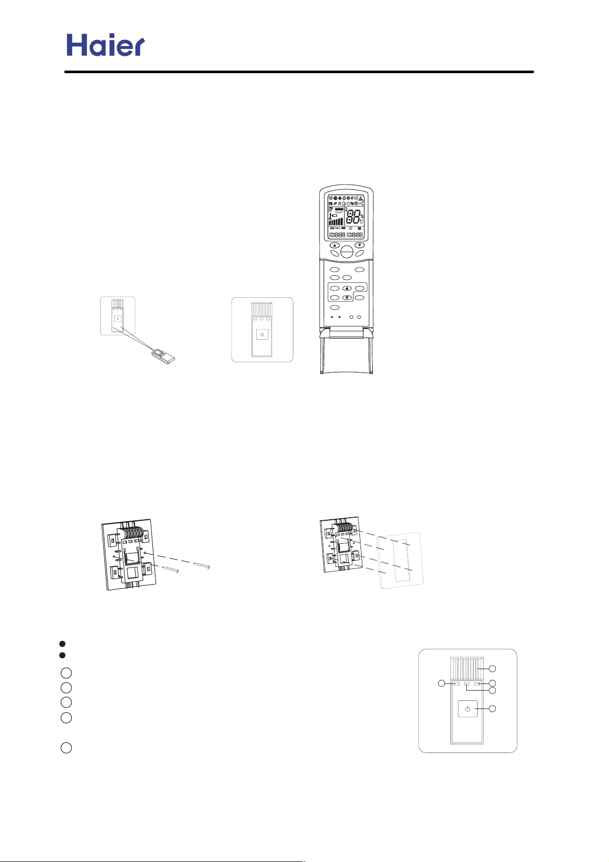
Commercial Air Conditioner Model: AU242FHBIA,
AU482FIBIA, AU48NFIBJA
7 NS lx+-2x 0xvx|4x0 l`MPQ
dy 2{x 3,|2 |15|0xw 27.xt,w|2 |15|2{-32 2{x 0x+-2x 0xvx|4x0L 7-3 vt,31x 2{x 0x+-2x 0xvx|4x0 l`MPQ
t,w 2{x 0x+-2xv-,20-**x0 slMcWQ 2- 0xt*|8x 2{x 0x+-2xy3,v2|-,N n{x |,12t**t2|-, -y 0x+-2x 0xvx|4x
31tzx y3,v2|-, t0xt1 y-**-51Z
n{x 0|z{2 y|z30x|1 t 0x+-2xv-,20-**x0L 5{|v{ vt, ux 31xw -,
+t2v{|,z 0x+-2xv-,20-* 0xvx|4x0
QNlx+-2xv-,20-* 0xvx|4x031|,z +x2{-w Z
o1x 0x+-2xv-,20-**x0 v-,20-* 2{x
0x+-2xv-,20-* 5|,w-5 -y 2{x 0x+-2x
v-,20-* 0xvx|4x0N
EC
Yaleam
lahjna
_jinljggal oienm
kga]ma klamm nda
^jnnji ?MVNO?nj _djjma
nda kljcl]h jb _j`a ?L?
mqdib
^gj^f
l`m`n
h_
hj_`
c`\gnc
ndh`l
adgn`l
K
[
Z
V
VPP
n`hk
ji
jaa
al`mc
^j_`
1x0|x1
]
\
a\i
mg``k
m`n
cdbcOmj
gj^f
gdbcn
0x+-2xv-,20-* 3,|21 t,w 2{x
0 t,w
lx+-2x 0xvx|4x0
lx+-2xv-,20-***x0
d,12t**t2|-, -y 0xvx|4xw|1.*t7
]xvt31x -y 2{x 2x+.x0t230x 1x,1|2|4xwx4|vxL w- ,-2 |,12t** 2{x 0xvx|4xw|1.*t7 t2 120t|z{2 13,*|z{2.*tvxL
x|2{x0 |, y0-,2 -yt|0 -32*x2 z0|**L y-0 |2 |1 xyyxv2xw z0xt2*7 y0-+ v--* t|0 t,
w {xt2 t|0L 2{x 0xvx|4xw|1.*t7 |1
t2*xt12 RP++ w|12t,vx 2- 2{x t|0 -32*x2 z0|**N
m|,vx 2{x0x|1*|z{21x,1|2|4xwx4|vx 5{|v{ 0xvx|4x15|0x*x11 0x+-2x 1|z,t*L 1- w- ,-2 |,12t**xw ux{|,w 2{x
5|,w-5 v302t|,-0-2{x0-
u12tv*x1L |,-0wx0 ,-2 2- -u1203v22{x 1|z,t*N
h312 y|62{x 0x+-2xv-,20-* 5|0xyt0 y0-+ 120-,zx*xv20|v|27 I13v{ t12{x 5|0|,z -yx*xv20|v *|z{2L t|0 v-,wM
|2|-,x0L x2vNJ t,w 5xt~ x*xv20|v|27 I13v{ t12{x 5|0|
QNa|62{x 0xvx|4xw|1.*t75|2{ 1v0x51
-, 2{x 1x*xv2xw .*tvx
^-,,xv2|,z 5|0|,z +x2{-w -y 0xvx|4x0 Z
,z -y 2x*x.{-,xL |,2x0.{-,xL x2vNJN
RNk*tvx 2{x .t,x* -,2- 2{x y|6xw y0t+xL .t7 t22x,2|-,
2{t22{x y-30 v*t51 +312 ux .*tvxw |,2- 2{x
v-00x1.-,w|,zy-30 .-*x1-,2{x y0t+x
lxyx02{x |,w--0 3,|25|0|,z w|tz0t+ N
mtyx27 vt32|-,1 1xx 2{x x*xv20|vt*5|0|,z .t02 N
QN`+x0zx,v715|2v{
RNl3,,|,z *t+.Z q{x,2{x v-+.0x11-0 5-0~|,zL 2{|1*t+. u0|z{2N
S Nn|+|,z *t+.Z q{x,2{x 3,|2 uxx,1x22|,zn|+|,z 03,,|,zL 2{|1*t+. u0|z{2N
TNk-5x0*t+.Z \y2x0-.x,2{x 3,
|2L 2{|1*t+. u0|z{25{x,2{x 3,|2xx,2x0
6
9
8
7
5
{xt*2{ 03,,|,zL 2{x *t+. v{t,zx y0-+ -0t,zx 2- u*3x *t+.N
UNd,w--0 2x+.N 1x,1-0Z nx12 2{x 0--+ 2x+.x0t230xN
-69-
Page 70
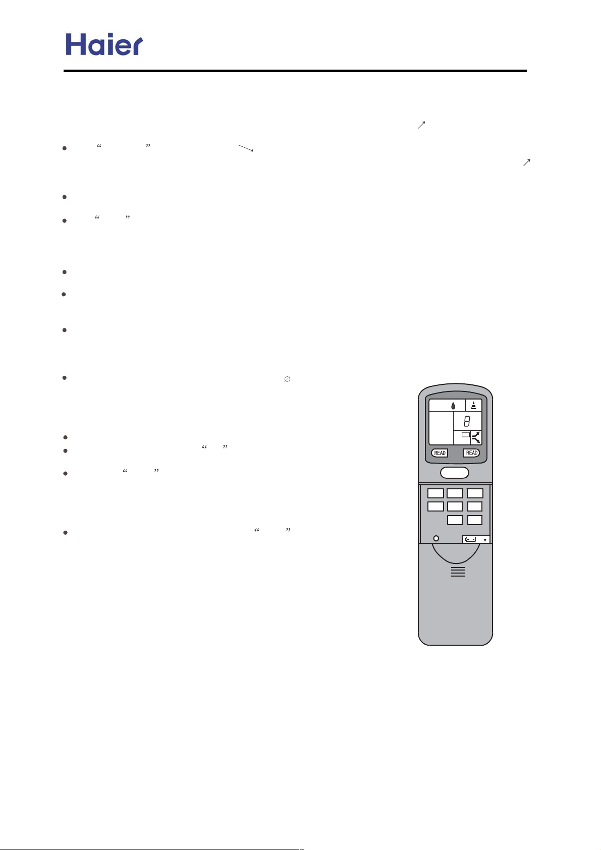
Commercial Air Conditioner Model: AU242FHBIA,
AU482FIBIA, AU48NFIBJA
7 vy {**/+00 0+1 ~.-1/.,,+/ {}|uwx
20 AYU_UMW
JT]QQ ^QOZYP^
30 F[Q]M_UZY
40
50 :
OZYYQO_UZY ZR [ZbQ] ^`[[Wd
MR_Q] _TQ ]QXZ_Q OZY_]ZWWQ] U^ OZYYQO_QP _Z [ZbQ] ^`[[Wd.PQRM`W_ ^dXNZW
_TQ `YU_ XZPQW bUWW NQ PU^[WMdQP ZY _TQ C<= MYP _TQ YQb UOZY +
+2+ ZR
+ ^TMWW
_]MY^XU__QP0
NQ
ZR ]QXZ_QOZY_]ZWWQ]
JTQ
I>C><J
RZ] _]MY^XU^^UZY ZR
M[[QM]^ RZ] ^Q__UYS
;`__ZY 9JTQ
[]QaUZ`^Wd ^Q_
UOZY +
+U^
OZPQ U^
PU^[WMdQP bTQY _TQ N`__ZYU^ RU]^_ []Q^^QP
^Q_0 AR
_TQ ^MXQ
ZR YQb OZPQ0 JTQ R`YO_UZY UOZY bUWW NQ
N`__ZY U^
^bU_OTQP RZ]
MYP _TQ
[]Q^^QP MSMUY.
_TQ UOZY
PU^[WMd UR _TQ N`__ZY U^
R`YO_UZY
OZY_UY`Z`^Wd []Q^^QP0
JTQ +HQMP+
N`__ZY9 G]Q^^UYS ZR _TU^ N`__ZY bUWW ]Q^`W_ UY^UX`W_MYQZ`^ PU^[WMdZR PQT
`XUPURdUYS MYP
_]MY^XU^^UZY UOZY^ ,NWMOV bM_Q] P]Z[ MYP[d]MXUP M^ ^TZbY UY_TQ RUS`]Q-
JTQ CZOV
U^ []Q^^QP._TQ UOZY+FRR+ M[[QM]^ZY _TQC<=. _TQYQcOQ[_ _TQ HQMPUYS N`__ZY.
^TUQWPQP bU_T _TQ
WZOV/ZY R`YO_UZY
DMOTUYQ Y`XNQ]
N`__ZY9 JTU^N`__ZY OMYNQ []Q^^QP MR_Q] YQbOZPQ _]MY^XU^^UZYU^ ^Q_0LTQY
N`__ZY^ bUWW
]QOQUaQ] OZPQ WZOVQP0 AR _TQ N`__ZYU^ []Q^^QP
U^ UYMO_UaM_QPRZ] MWW _TQ Z_TQ]
N`__ZY^0
MSMUY. UOZY
MWW _TQ
+FRR+ PU^M[[QM]^MYP _TQ
N`__ZY ,EZ02 _Z EZ06 `YU_-9 AR _TQ N`__ZY U^ []Q^^QP. M XMOTUYQ ^Q]UMW
_TQ N`__ZY
N`__ZY U^
PU^[WMdQP bU_T M RWM^TUYS R]Q\`QYOd ZR 2@e0
IQ_ XMOTUYQ Y`XNQ] 7.89 []Q^^ N`__ZY 6.MYP bU_TUY 3^QOZYP^ []Q^^ N`__ZY 2. _TQY WZZ^Q _TQX ^UX`W_MYQZ`^Wd.
7 bUWW PU^[WMd UY _TQ ^O]QQY. bTUOT ^_MYP^ RZ] ^QWQO_UYS `YU_ 70 :YP _TQY []Q^^ N`__ZY+^Q_+. dZ` OMY ^Q_ `YU_
70JTQY []Q^^ +H>:=+ _Z OZYRU]X UR _TQ `YU_ Y`XNQ] U^ ]UST_0 LU_T _TQ ^MXQ XQ_TZP. ^Q_ `YU_ EZ080
DMOTUYQ Y`XNQ]
+^Q_+
C<=0 DMOTUYQ Y`XNQ] RWM^TUYS bUWW NQ ^Q_ MYP_]MY^XU__QP UR _TQ N`__ZY U^ []Q^^QP.
Y`XNQ] ^_Z[^ RWM^TUYS MYP M _]MY^XU^^UZY UOZY ,_TQ NWMOV [d]MXUP ^TZbY
M[[QM]
JTQ +HQ^Q_+
ZR _TQ
^Q__UYS. MYP
M[[QM] ZY
JQ^_
G]Q^^ KYU_
G]Q^^ _TQ
bUWW NQ
G]Q^^ _TQ
^Q_ XMOTUYQ
`YU_ U^
[ZbQ] UYPUOM_Z]
Y`XNQ] U^
LTQY ^Q__UYS
Y`XNQ] ]QXZ_Q
ZY _TQ
K^`MWWd
ZY _TQ C<=0
N`__ZY9 AY^Q_ M [ZUY_QP _ZZW ,
HQ^Q_ N`__ZY0>aQ]d []Q^^ ZR _TQ _ZZW bUWW ]Q^Q_ _TQ QcU^_UYS
_T]QQ ^QOZYP^ WM_Q]. UYU_UMW Z[Q]M_UZY XZPQ bUWW
_TQ C<=0
ZR ]QXZ_QOZY_]ZWWQ] ,UQ0EZ0 4 `YU_-
4 N`__ZY._TQ Y`XNQ] 4 RWM^TQ^ bU_T MR]Q\`QYOd ZR 2@e0
XMOTUYQ Y`XNQ] ^Q_ N`__ZY. _TQ ^QWQO_QP `YU_ Y`XNQ]
^Q_ MYP _]MY^XU__QP _Z_TQ ]QOQUaQ] ZR _TQ `YU_0
HQMP N`__ZY MYP _TQ ^QWQO_QP `YU_ ^_M]_^ ]QMP _TQ
Y`XNQ]0AR XMOTUYQY`XNQ] ZR ^QWQO_QP UYPZZ]
OZ]]QO_Wd PU^[WMdQP.,?WM^T Y`XNQ] ZR _TQ UYPZZ] `YU_
UX[WUQ^ XMOTUYQ Y`XNQ]- ^Q__UYSZR XMOTUYQ
^`OOQ^^R`W Z] aUOQ aQ]^M0
U^ OZX[WQ_QP. []Q^^ _TQ
OZY_]ZWWQ] ZYWd- MYP _TQ UOZY CZOV/ZY M[[QM]^
C<=. _TQY _TQ XMOTUYQY`XNQ] ZR _TQ UYPZZ] `YU_ U^ WZOVQP0
XMOTUYQ Y`XNQ]^ PZ YZ_ YQQP _Z NQ WZOVQP0
N`__ZY9 JTU^ N`__ZY OMY NQ ^Q_ bTQY XMOTUYQ Y`XNQ] RWM^TQ^
_TQ XMOTUYQ
CZOV
3XX- UY_Z
_TQ TZWQ
N`__ZY. ,RZ] YQb
op
opgk
qnrn s
UY _TQ
gh
F??
rns
opgi
opgl
CF<B
RUS`]Q- bUWW
opgj
opgm
I>C><J
ZY _TQ
^WUST_ ^Z`YPXMd NQ []ZP`OQP Nd _TQ UYPZZ] `YU_ bTQY _TQ
^USYMW R]ZX
_TQ ]QXZ_Q OZY_]ZWWQ] U^ ]QOQUaQP0
++
NQ
EZ_Q9 =Z
YZ_ ^Q_ XMOTUYQ Y`XNQ]^ RZ] XZ]Q _TMY ZYQ UYPZZ] `YU_
NQRZ]Q M
XMOTUYQ Y`XNQ]
WM[^Q ZR 31 ^QOZYP^ MR_Q] OZX[WQ_UZYZR ^Q__UYS ZR
ZR M UYPZZ] `YU_0
-70-
Page 71
Commercial Air Conditioner Model: AU242FHBIA,
AU482FIBIA, AU48NFIBJA
8. Electrical Control Functions
8.1 Outdoor control principle:
No Item AU242FHBIA AU482FIBIA AU48NFIBJA
1. Startup period in cooling
mode: high
2. Cool, Dry mode:
ƽCurrent state is Fan OFF
mode:
TC˚21ć: low speed
ƽ Current state is low
speed:
TC˚30ć, med speed
TC˘15ć, fan off
ƽ Current state is med
speed:
TC˚42ć, high speed
TC˘22ć, low speed
ƽ Current state is high
speed:
Fan motor
1
control
2 EEV In COOL, DRY, DEFROST state, EEV will open fully with 480 pulse.
TC ˘ 39 Current state is
med speed:
1. Startup period in heating:
High speed
2. Running state in heating:
ƽTA˚17ć
running units capacityİ
1HP, low speed will be
ON and OFF in turns.
ƽOther condition:
TE˘7ć, high speed
TE˚10ć, low speed
1. Startup period in cooling
mode: high
2. Cool, Dry mode:
ƽ Current state is Fan OFF
mode:
TC˚37ć: low speed
ƽCurrent state is low speed:
TC˚50ć, med speed
TC˘30ć, fan off
ƽCurrent state is med speed:
TC˚47ć, high speed
TC˘40ć, low speed
ƽCurrent state is high speed:
TC˘41ć, med speed
ƽIn low speed:
TC˘40ć, lower fan off
TC˚42ć, lower fan startup
1. Startup period in heating:
High speed
2. Running state in heating:ƽ
TA˚17ć
running units capacity İ
1HP, low speed will be ON
and OFF in turns.
ƽOther condition:
TE˘7ć, high speed
TE˚10ć, low speed
3. TE˚14ć, lower fan off
TE˘12, lower fan startup
1. Startup period in cooling
mode:
TA˚16
TAİ16ć, low speed
2. Cool, Dry mode:
ƽTA˚32ć, high speed
ƽ15ćİTA˘31ć:
TC˚45ć, high speed
40 ć˘TC ˘ 44 ć , med
speed
TC˘39ć, low speed
ƽTA˘15ć:
TC˘30ć, fan off
TC˚50ć, low speed
ƽIn low speed:
TC˘36ć, lower fan off
TC˚38ć, lower fan startup
ƽ 17 ć˚TA ˚ 15 ć, low
speed
ƽ 14 ć˚TA ˚
speed
ƽTA˘9ć, high speed
ć, high speed
1. Startup period in
heating:
TAı20ć, low speed
TA˘20ć, high speed
2. Running state in
heating:
ƽTA˚17ć:
running units capacityİ1
HP, low speed will be ON
and OFF in turns.
running units capacity ˚
1HP, low speed
10 ć , med
-71-
Page 72
Commercial Air Conditioner Model: AU242FHBIA,
AU482FIBIA, AU48NFIBJA
control In heating mode, EEV will be adjusted due to the overheating value: SH= TS-TC
1. Adjust range: according to the compressor frequency, min open angle of EEV will be
different: high frequency, 120; med frequency, 110; low frequency, 90; the max open
angle: 470/350
2. Overheating modification: according to the discharging temperature, modify the
overheating value, when Td>100ć, overheating value will decrease 2 at the standard
overheating value; when Td İ 70 ć , overheating value will add 2 at the standard
overheating value
1. Secure operation conditions of 4-way valve:
ƽ After the outdoor receives the heating signal from indoor unit, if the 4-way valve is
not electrified before the compressor starts up, the unit will enter the 4-way valve
secure operation.
ƽ After defrosting is over, the unit will enter the 4-way valve secure operation.
2. 4-way valve secure operation control:
ƽ In heating mode, After the outdoor receives the startup signal from indoor unit, the
compressor will start up, (fan motor shutoff, EEV close) and when the frequency rises up
to 50Hz for 10 seconds, 4-way valve will reverse (meanwhile, fan motor will enter the
target speed, EEV enters the open angle of soft startup) and the unit enters soft startup
period.
ƽ In defrosting, when the defrost condition is met, the compressor frequency will
decrease to 50Hz, 4-way valve will reverse (meanwhile, fan motor will enter the target
speed) and the unit enters soft startup period.
3. 4-way valve control in OFF state:
4-way valve will close after compressor stops for 30 minutes.
1. Enter condition:
when compressor
runs for 45 minutes
in all in heating
1. Enter condition: when compressor runs for 45 minutes in
all in heating mode, by checking TE and TA, if the below
conditions can be met for continuous 5 minutes, the unit
will enter defrosting operation: TEİChTAˉ¢, herein,
ƽC˖TA˘0ć, C=0.8; TAı0ć, C=0.6
ƽ¢˖set as 12˄L˅,10˄M˅,8˄H˅ according to the
actual condition. At the easily defrosting place, set as H; at
the not-easy-defrosting place, set as L; when out of factory,
set as M
ƽTemperature limitation: -15ćEİTEİ2ćE
mode, by checking
TE and TA, if the
below conditions can
be met for
continuous 5
minutes, the unit will
enter defrosting
operation:
ƽWhen Ta˘2ć, TA-TE
ı9ć for continuous 2
minutes; or Te ˘ -12 ć
for continuous 5 minutes;
ƽWhen Taı2ć, Te˘-5
ć for continuous 5
minutes;
3
Defrosting
4
4-way
valve
secure
operation
control
-72-
Page 73
Commercial Air Conditioner Model: AU242FHBIA,
AU482FIBIA, AU48NFIBJA
2. Defrosting control:
When defrosting condition is met, compressor frequency will go down to the min.
frequency, and 4-way valve will be powered off and turn into cooling mode (fan motor off,
EEV in soft startup open angle); compressor frequency rises up to 78Hz and begins to
defrosting operation.
3. Quit condition:
ƽTE is over 7ć for 60 seconds in all or is up to 12ć, defrosting is over;
ƽDefrosting accumulative time is up to 10 minutes, defrosting is over.
5
Unloading
6
valve SV1
7
valve SV2
Pressure
8
Electric
heater
control
control
Spray
control
switch
control
1. When TAİ27ć, if the compressor stops running, electric heater will be electrified;
2. When TAı27ć, or when compressor starts up, electric heater will be off; and temp.
difference is 5ć.
1. To balance pressure: it will open 1 minute before compressor starts up, and keep open
in soft startup period after compressor starts up until the soft startup is over; in the
remaining operation and 10 minutes later after shutoff, SV1 will open;
2. Improve low pressure: in heating mode, when (TCǃTSǃTE)min. valueİ-13ć SV1
open, temp. difference is 3ć.
Adjust the SV2 according to the discharging temperature:
when TDı115ć, SV2 will open; when TDİ110ć, SV2 will close.
High pressure switch protection:
ƽWhen input level of pressure switch is 1, it shows there is no protection.
ƽWhen input level of pressure switch is 0 for a while, it shows high pressure beginning;
compressor stops and the unit alarms. The alarm can be resumable, the unit will alarm in
3 minutes when compressor is standby.
Low pressure switch protection:
ƽWhen input level of pressure switch is 1, it shows there is no protection.
ƽ When compressor is running, if low pressure switch has acted for 3 minutes
continuously, the unit will alarm. When compressor stops, if low pressure switch has acted
for 30 seconds continuously, the unit will alarm. When compressor starts up, low pressure
switch will be shielded within 3 minutes.
ƽIn defrosting and in 6 minutes after defrosting is over, low pressure switch will be
shielded.
-73-
Page 74
Compress
or capacity
9
output
control
Commercial Air Conditioner Model: AU242FHBIA,
AU482FIBIA, AU48NFIBJA
In cooling mode, frequency will be calculated according to
the horse power of the running indoor units:
1. Every indoor unit will confirm 8 capacity codes
according to the difference between the set temperature
and the ambient temperature; then add all the capacity
code of the running indoor unit.
2. Divide the outdoor capacity into 13 capacity classes due
to the frequency; every capacity class is corresponding
with the different indoor capacity code; modify the relative
indoor capacity code due to the different ambient
temperature;
3. Compressor will confirm its target frequency according
to the sum of indoor capacity code;
Heating target frequency will be confirmed due to the indoor running horse power and the
outdoor ambient temperature:
F=C1(P-C2)+C3(7-T)+C4+C5(C6-TZ)
Herein: C1=16; C2=160; C3=32; C4=4500; C5=300; C6=45.
Cooling target frequency
will be confirmed due to the
indoor running horse power
and the outdoor ambient
temperature:
F=C1(P-C2)+C3(T-35)+C4
Herein: C1=22, C2=160,
C3=64, C4=4200;
-74-
Page 75
Commercial Air Conditioner Model: AU242FHBIA,
8.2 Indoor electric control functions:
AU482FIBIA, AU48NFIBJA
No
1 EEV control
Control
item
In cooling mode, the adjustment by the over heating: SH= TC1(gas
pipe)-TC2˄liquid pipe˅
1. Adjust range: min. angle: 60/65, max. angle: 470/350˄data will take
EEPROM as standard˅
2. Overheat modification: according to the discharging temperature, modify
the overheat state, if Td > 100 ć, the overheat value will add 2 degree at the
base of standard degree;
3. Open modification: when EEV is at min. angle, the unit will measure the
difference between Tliquid and Ta at the interval of 5 minutes, if the
difference is within 5 degree, the valve will be back to base open angle and
modify the open angle due to the overheat state
In heating mode, adjust the open angle according to the conformity of liquid
pipe temperature.
1. Adjust range: indoor unit startup, min open angle: 100, max open angle:
470; indoor unit standby: open angle: 60.
2. The indoor EEV open angle will depend on the temperature difference
between indoor liquid pipe temp. and average liquid temp. of all running
indoor units. (if lower than average temp., the valve will open; if high than
average temp., the valve will close.
AE*FCBKA AS*FCBHA AB*FCBIA
Anti-freeze control in cooling mode:
ƔWhen liquid pipe temp. is below 7 degree for 40 minutes, or when liquid
pipe temp. is below 4 degree for 10 minute, the unit will enter anti-freeze
function. At this time, the current indoor EEV will close, and the fan motor will
turn into low speed from the current speed.
ƔAfter the anti-freeze function has worked for 10 minutes, and liquid pipe
2
Fan motor
control
temp. is over 7 degree, the unit will quit anti-freeze control (take the data in
EEPROM as standard).
Anti-cold air control in heating mode:
ƔWhen liquid pipe temp. is below 33 degree, indoor fan speed will turn into
low speed from the set speed; when liquid pipe temp. is below 25 degree,
indoor motor will stop.
ƔWhen liquid pipe temp. is over 30 degree, indoor fan speed will turn into low
speed from stop; when liquid pipe temp. is over 35 degree, indoor motor will
enter the set speed (take the data in EEPROM as standard).
-75-
Page 76
Commercial Air Conditioner Model: AU242FHBIA,
AU482FIBIA, AU48NFIBJA
8.3 Temperature compensation adjustment (only for indoor unit with new PCB-AB**FCBIA):
For infrared control type unit, the temperature compensation can be adjusted. But for wired control
type unit, there is no temperature compensation.
Set the EEPROM by SWING (or SLEEP) button. For example:
Infrared control—in heating mode, press “ON/OFF” button to switch on the unit. Take the 24 degree
set temperature as the base point, press SWING (SLEEP) within 5 seconds, it will sound 2 times,
the unit will enter the heating temperature compensation mode, at this time, if you set the
temperature to 25 degree and switch off, the temperature compensation will be +1 degree; if you
set the temperature to 26 degree and switch off, the temperature compensation will be +2 degree,
and so on, the max. compensation can be +6 degree ( 30 degree); if you want to cancel the
compensation, adjust the temperature back to 24 degree.
Infrared control—in cooling mode, press “ON/OFF” button to switch on the unit. Take the 24 degree
set temperature as the base point, press SWING (SLEEP) within 5 seconds, the unit will enter the
cooling temperature compensation mode, at this time, if you set the temperature to 23 degree and
switch off, the temperature compensation will be -1 degree; if you set the temperature to 22 degree
and switch off, the temperature compensation will be -2 degree, and so on, the max. compensation
can be -8 degree ( 16 degree); if you want to cancel the compensation, adjust the temperature back
to 24 degree.
Read the temperature compensation value:
Infrared control type—change to cooling mode, the set temperature is 30 degree, in high speed.
Press SWING (SLEEP) 7 times within 5 seconds, the running LED will flash as the current temp.
compensation value.
Infrared control type—change to heating mode, the set temperature is 16 degree, in high speed.
Press SWING (SLEEP) 7 times within 5 seconds, the running LED will flash as the current temp.
compensation value.
8.4 Unit debugging:
1. Confirm indoor unit quantity
After the unit is electrified, you can check the indoor unit quantity by the outdoor dip switch or the
testing board. The display quantity must be in accordance with the actual quantity. If not, please
check if there is repeated unit No. or if the dip switch is broken, and if the communication wire is
connected correctly.
2. Confirm indoor EEV
FAQ:
2.1 The EEV communication wire is not in accordance with the indoor unit. If all the indoors are
running, the operation will be normal; when the only one indoor unit is running and it can not cool,
while the EEV of the unit not running opens.
2.2 The live wire and the neutral wire of the EEV power cable is not in accordance with those of
indoor unit power cable, E7 failure occurs.
2.3 The coil temperature sensor is not in original place or not fixed well, which cause EEV not work
properly. The efficiency will be bad or outdoor unit will be liquid return.
-76-
Page 77
Commercial Air Conditioner Model: AU242FHBIA,
y
AU482FIBIA, AU48NFIBJA
Only No.1 unit in cooling
If No.1 unit in cooling
If No. 1 unit in cooling—if yes, OK
If not
Short connect the corresponding terminal,
open the EEV compulsorily. If it can open,
check if the EEV communication wire is in
accordance with that of indoor unit and modif
Can’t open
Check if EEV is installed properly, tap the EEV body, or reset.
Switch on all the indoor units in turn
.
Still not
Replace EEV PCB
Still not
If the refrigerant of the unit not running not
flow—if yes
If the refrigerant flows, check if the EEV
communication wire is in accordance
with that of indoor unit and modify.
If yes
Replace EEV
-77-
Page 78
3. Confirm cooling operation
(
Commercial Air Conditioner Model: AU242FHBIA,
AU482FIBIA, AU48NFIBJA
start
Set the unit in cooling mode and begin to run
If indoor unit blows cold air
If air circulation is OK
Make all indoor units running
If temp. drop between air outlet/indlet is normal
Once outdoor stops, the unit
must run again 2 minutes
and a half later.
Confirm compressor state
Confirm the louver direction
If the operation voltage is OK
230Vf10ˁ˅
If the running current is 15% of the
nominal value (at max. frequency)
If working pressure is normal
normal
Check power voltage and power
circuit.
Check indoor/outdoor temp.
Check piping length and
refrigerant charge.
Check compressor running
frequency and if there is abnormal
noise
-78-
Page 79
4. Confirm heating operation
r
Commercial Air Conditioner Model: AU242FHBIA,
AU482FIBIA, AU48NFIBJA
start
Set the unit in heating mode and begin to run
If blowing warm air?
If air circulation is OK
Make all indoor unit running
If temp. drop between air outlet/indlet is normal
Once outdoor stops, the unit
can work only 2 minutes
and a half later
Confirm compressor state
Confirm the louver direction
If the operation voltage is OK
˄230Vˇ10ˁ˅
If the running current is 15% of the
nominal value (at max. frequency)
If working pressure is normal
normal
Check power voltage and powe
circuit.
Check indoor/outdoor temp.
Check piping length and
refrigerant charge.
Check compressor running
frequency and if there is
abnormal noise
-79-
Page 80
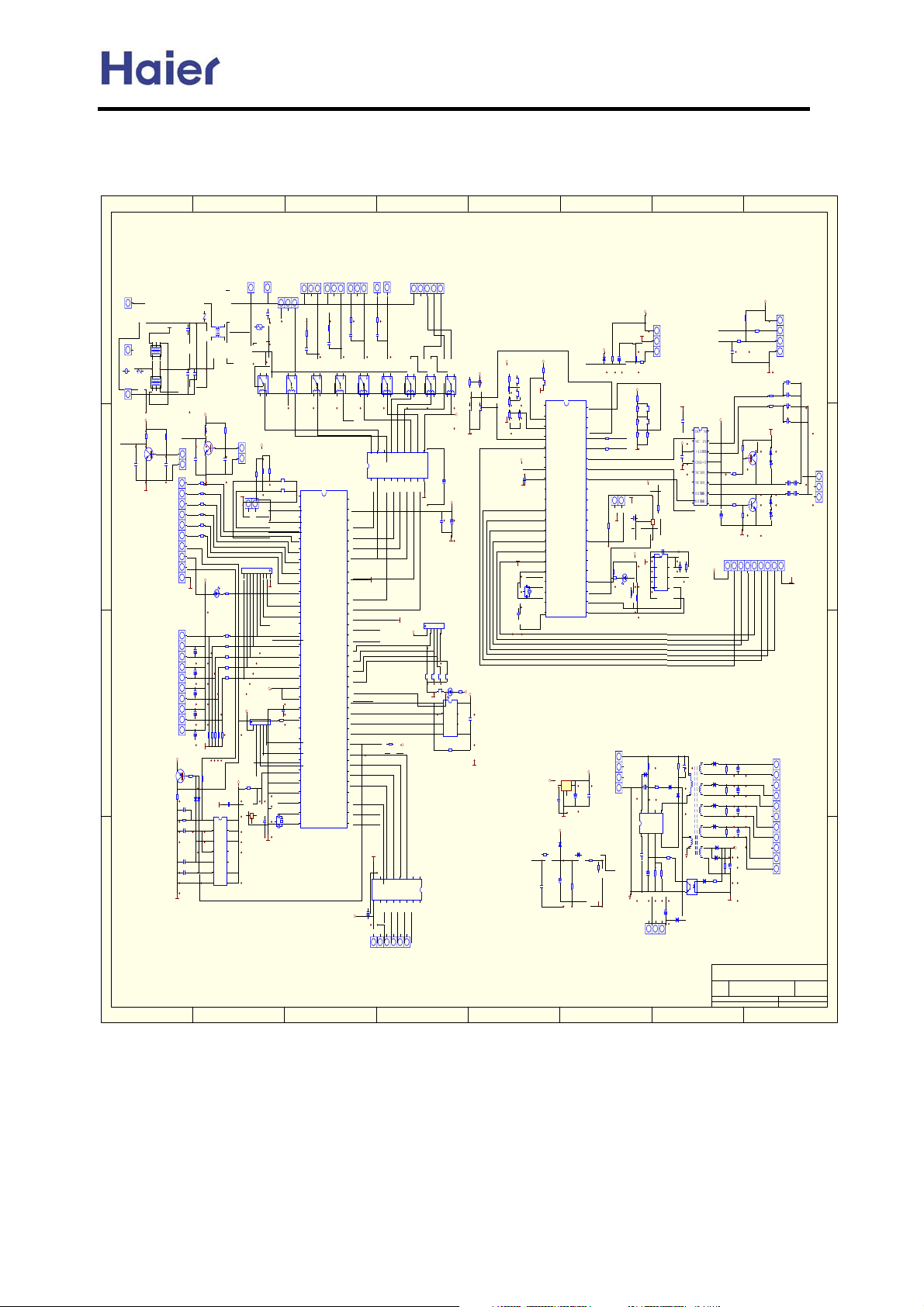
8.5 PCB information
AU242FHBIA PCB circuit diagram:
Commercial Air Conditioner Model: AU242FHBIA,
AU482FIBIA, AU48NFIBJA
7654321
8
CN21
CN9
CN10
D
CP250
CN11
CP250
ZEN2
C1
FDG_1
561
CN12
CP250
+5V
R97
1K
LPRE_SW
C24
103
GND
C
B
A
1 2 3 4 5 6 78
ZEN1
561
L1
CT_IN
8550
T38003
C3
0.47UF
C5
C4
472
472
+5V
R38
R39
1K
1K
HPRE_SW
DQ5
CN34
9013
C36
C22
104
103
CN1
R24330
GND
R25330
R26330
R27330
R28330
R29330
+5V
R30
GND
560
LED3
RED
CN14
+5V
DQ1
R35
1K
C21103
GND
1K
R40
7(
R411K
7'
CD21
R421K
7$
4.7UF
R431K
76
CD22
R441K
7&
4.7UF
CD23
4.7UF
CD24
4.7UF
R17 20K
R21 20K
R23 20K
CD25
R20
R22
4.7UF
20K
20K
GND
R18
R11
10K
100
VD6
VD7
4148
4148
GND
C18103
R12
1
100K
2
C19
3
103
IC8
4
4011
C20103
5
6
7
GND
4
3
5
CT1
803
1
2
1
2
CT2
803
4
3
5
R98
1K
DQ6
9013
C25
104
C6
0.47UF
PTC1
RL1
JTN1AS
CN16
+5V
R50
R51
R88
10K
10K
10K
DOWN
UP
GND
CN5
SERIAL
CA1
1000PF*8
GND
AC2_IN
AC1_IN
+5V
+5V
RA2
RA-4(10KX4)
1
2
3
4
5
TX_IN
+5V
R6210K
C43
104
CX1 10MHz
14
C23
104
13
IC9
PST600D
12
GND
11
10
9
8
жÔØ
CN35
R19
100
RL9
JQ-1A
SW07
SW06
1
2
3
4
5
6
7
8
9
10
11
12
13
14
15
16
17
18
19
20
21
C46
104
22
R34
1K
23
24
25
26
27
28
29
30
31
32
CN22
CN23
Ñõ°É ÅçÉä ËÄͨ
R9
100
C9
103
C14
103
RL2
JQ-1A
6(5,$/29
)B83
)B'2:1
3:0B=
3:0B<
3:0B;
3:0B:
1&B*1'
3:0B9
3:0B8
+($7(5
(55
&23+($7
$&B&203
IC1
$&B,1
MB89P857
Pd(NOP)
Te
Td
Ta
7F
Ts
$9&&
$95
$966
,30
HIV
LOWV
7;B,1
V-IN
1&B*1'
,17
567
02'
02'
3(1*6(
;,1
3)&B287
;287
*1' 1&
)$1B6:
7;B287
'&567
309B$
309B%
309B&
309B'
3)&B,1
CN8
CN6
CN7
CN4
¼ÓÈÈ´ø ·ç»ú
R4
R5
100
100
C8
C7
103
103
+5V
+5V
RL3
RL4
JQ-1A
RL5
JQ-1A
JQ-1A
RL8
JQ-1A
SV2
14
13
12
11
10
15
16
17
18
IC5
ULN2803
2
1
3
4
5
6
7
8
64
63
62
61
0,'
60
59
3&7
LOW
58
:$<
57
GND
56
1&
55
54
53
HPRE_SW
52
51
LPRE_SW
50
49
48
47
46
TX_OUT
45
&6
44
6.
43
',
42
'2
41
40
39
38
37
36
35
PFC_OUT
34
PFC_IN
33
GND
8
9
CD16
16V/100UF
+12V
CN15
9
GND
GND
RA-4(10KX4)
+5V
1
2
J6
R67
+5V
10K
1
2
3
4
5
6
7
IC4
ULN2003
16
15
14
13
12
11
10
SV2
+5V
RL6
R87
R86
JQ-1
2K
10K
RL7
JQ-1
J7
J8
+12V
JP1 JP2
GND
CD14
16V/100UF
+5V
C28
CD17
104
16V/100UF
GND
RA1
3
5
4
J5
J4
J3
CJ1
LED4
R99
+5V
+5V
10K
GND
RED
1
8
2
7
C27
IC7
104
3
6
93C46
4
5
R66
10K
GND
R91
10K
R77
CN25
2K
R78
GND
2K
CN24
COOL
R79
1
2K
R80
HEAT
R81
2
SS/TEST
2K
100K
3
GND
H,C
4
JP2
5
4051IN
6
+5V
7
8
C49
104
9
GND
10
11
595SI
12
595SCK
13
595RCK
14
4051S1
15
4051S2
16
GND
4051S3
17
18
CX2 16.0MHz
19
20
21
C44
104
+5V
AC1_IN
AC2_IN
CN26
IC2
42
P33
P32
41
P34
P31
40
P35
P30
39
P36
P10
38
P37
P11
37
P12
VREF
36
P13
AVDD
35
P14
AVSS
34
P40
P15
33
P41
P07
32
P06
P42
31
P05
P43
30
P44
P04
29
P45
P03
28
P46
P02
27
P47
P01
26
VSS
P00
25
XIN
P20
24
XOUT
_RST
23
TEST
P22
22
VDD
P21
TMP86FH46N
+5V
IC11
7805
+12V
7805
C48
CD18
C30
104
220UF
104
GND
+5V
VD8
4148
VD1
R48
R36
1K
4148
1K
CD13
R37
100UF
C15
1K
103
+5V
VD9
4148
JP1
TO857
FR857
FR1007
1007A
1007B
SERIAL
COM_LED
SCL
SDA
R15
180K
GND
+12V
CN30
GND
R82
CD15
R83
R72
3K
100UF
1K
10K
+5V
R92
STOP
2K
R93
2K
R94
2K
TX_OUT
R95
R84
100
2K
TX_IN
R85
100
CN19
GND
C23
104
GND
R31
10K
+5V
R1010K
R32
560
LED2
RED
R46
10K
CN3
CT_IN
SGND
GND
SW05
START
GND
+5V
IC10
PST600D
GND
R47
10K
ZD2
18V
CD3
10UF
7
8
*1'
62)7)%,6
1
2
C29
104
CD1 2.2UF
CN32
R96
100K
1
2
3
4
9&&
SW04
R3
560K/1W
IC3
C47
MM1007
101
'
2
1
&
1
16
1
&
,1
2
15
+12V
9&
,1
3
14
104
*1'
9
4
13
C45
'2B
D
1
&
5
12
GND
1
&
'2B
$
6
11
',1
%
'2B
%
7
10
',1
$
'2B
E
8
R68
10K
C26 104
24C02
IC6
R71
10
6
5
1&
IC13
'5$,1
ICE2A165
3
4
R7
2
R6
2
9
+5V
8
7
R45
R63
+5V
10K
10K
6
5
T1
VD14FR102
T28051
R2
C2
47K/2W
472
VD15
VD12
FR102
FR102
VD16
VD11
FR106
FR102
VD17
FR102
VD20HER204
SGND
IC12
TLP421
CD20
VD22
100UF
FR102
VD21
HER204
ZD1
R1
471
11V
Title
Date: 3-Sep-2005 Sheet of
File: C:\Documents and Settings \dupeng\
R8
27
+5V
A2
PFC_OUT
PFC_IN
C42
103
CD2
1UF
CN27
XP-9A
R53
5.6K
R545.6K
R56
R76
5.6K
GND
+5V
CN31
R74
10K
R73
560
R75
1K
GND
R13
100K
R14
100K
GND
R70
ZD5
4.7K
DQ3
5.6V
9013
ZD6
5.6V
R64
10K
DQ4
R65
ZD3
9013
5.6V
10K
R69
ZD4
4.7K
5.6V
GND
9
CN2
CD8
100UF
CD9
100UF
R55
CD10
5.6K
100UF
5.6K
CD11
100UF
+12V
CD12
1000UF
Number RevisionSize
Drawn By:
Ḡ䴶\ᴼᑇথ䖛ᴹⱘ݇Ѣ80ⱘ
D
C13
104
C12104
C10104
C11
104
CN13
CD6
CD4
$
100UF
100UF
%
CD7
CD5
100UF
100UF
C
GND
B
A
-80-
Page 81
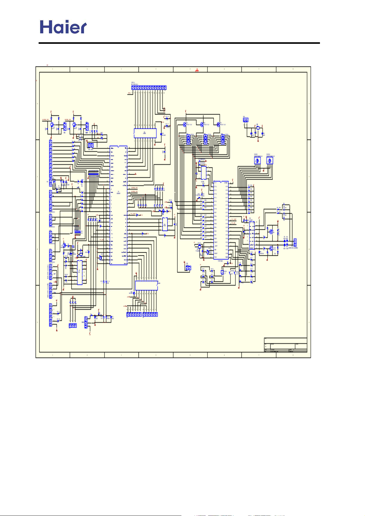
AU482FHBIA PCB circuit diagram:
Commercial Air Conditioner Model: AU242FHBIA,
AU482FIBIA, AU48NFIBJA
-81-
Page 82
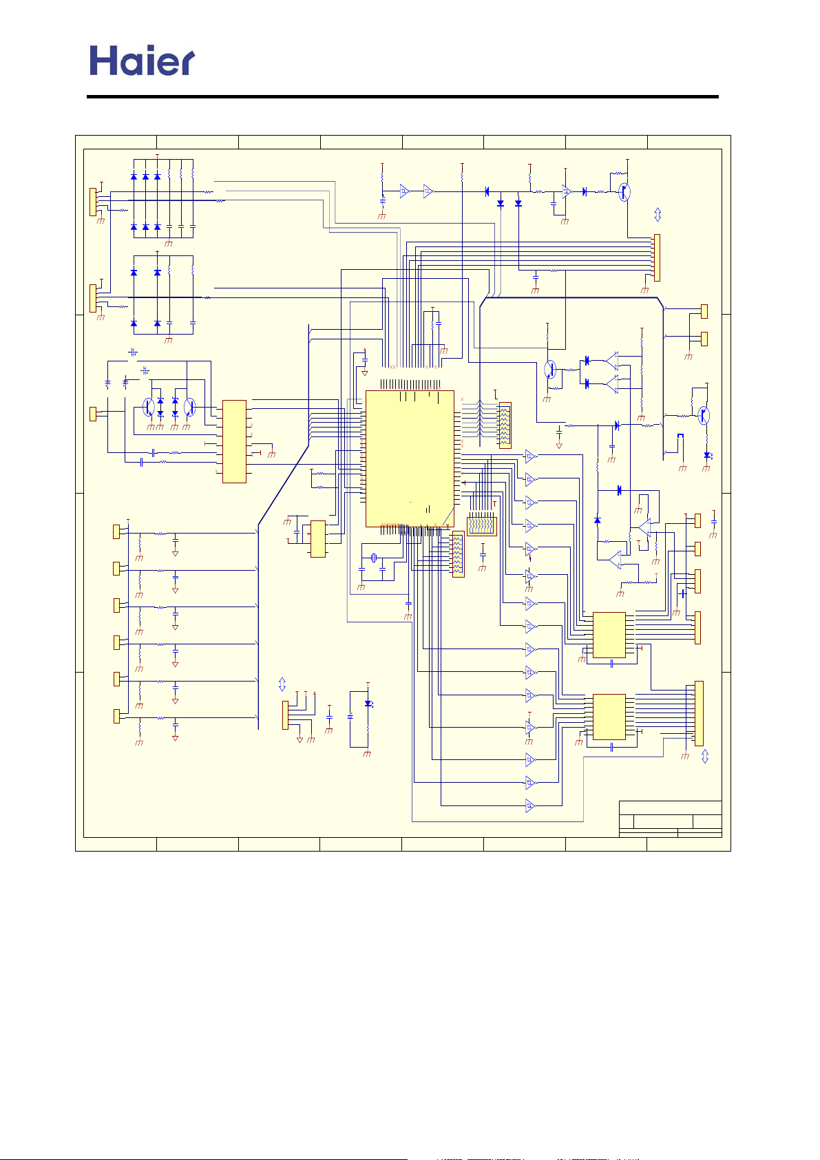
Commercial Air Conditioner Model: AU242FHBIA,
Æ
AU482FIBIA, AU48NFIBJA
AU48NFIBJA PCB circuit diagram:
+5V
R303
R302
R301
4.7k
4.7k
4.7k
D303
D302
D301
6 - 1N4148
+5V
+5V
SK
CN302
TXD
1
RXD
2
GND
3
4
R306
ÏÔʾ¹¤×°
5
100¦¸
XH5-5Ȯ
D
4 - 1N4148
+5V
+5V
CN303
SK
TXD
1
RXD
2
GND
3
4
R310
5
485ͨѶ
100¦¸
XH5-5˦
C310
100uF
DA
CN304
C
DB
1
2
HBS
XH2-2ºì
CN311
+5V
Tsink
1
2
XH2-2½ðÉ«
CN312
+5V
Tt
1
2
XH2-2ÂÌ
B
CN313
+5V
1
Te
2
XH2-2°×
CN314
+5V
1
Ta
2
XH2-2Ȯ
CN315
+5V
1
Ts
2
XH2-2ºÚ
CN316
+5V
1
Td
2
XH2-2˦
A
1 2 3 4 5 6 78
D306
D305
D304
+5V
D308
D307
D310
D309
C309
100uF
C307
100uF
C308
100uF
4 - Z_5.6V
Z302
QN301
Z303
NPN_2222A
C311204
R312
C312204
100k¦¸
+5V
R313
270¦¸
R314
10k¦¸/1%
R315
270¦¸
R316
10k¦¸/1%
R317
270¦¸
R318
10k¦¸/1%
R319
270¦¸
R320
10k¦¸/1%
R321
270¦¸
R322
10k¦¸/1%
R323
270¦¸
R324
47k¦¸/1%
C302
471
R307
4.7k
C305
471
R311100k¦¸
R304
P3.2
100¦¸
R305
TXD1
100¦¸
RXD1
C303
C304
471
471
R308
4.7k
R309
TXD0
100¦¸
RXD0
C306
471
Z304
QN302
IC309
P2.3
9
8
d_outb
Z305
NPN_2222A
P0.7
C313
472
P0.5
C314
472
P0.4
C315
472
P0.3
C316
472
P0.2
C317
472
P0.1
C318
472
D_INA
D_OUTB
D_OUTA
d_outa
Vcc
IN2
IN1
NC
MM1007
D_INB
D_OUT
P2.4
7
6
NC
5
NC
4
GND
3
+12V
Vin
2
NC
P2.2
1
10
11
12
13
+5V
14
15
16
+12V
+5V
+5VA
GND
GNDA
CN202
+5V
CN301
1
2
3
4
5
XH5-5°×
P0.0
P0.7
P0.5
P0.4
P0.3
P0.2
P0.1
P0.0
+5V
R326
2.7k¦¸
R327
2.7k¦¸
P2.1
IC302
P2.7
4
5
DO
GND
C320
104
+12V
P2.5
6
3
ORG
DI
7
2
P3.4
DC
SK
8
1
VCC
CS
93C66
+5VA
+5V
+12V
C331
104
+5VA
C319
104
54
p0.6/a6/t1clk/pm.2
55
ANGND
56
Vref
57
P0.5/A5/PM.1
58
P0.4/A4/PM.0
59
P0.3/A3
60
P0.2/A2
61
P0.1/A1
62
P0.0/A0
P2.1
63
NC
64
P2.0/EPA0/PVER
65
P2.1/SCLK0/BCLK0/PALE
P2.2
66
NC
P2.3
67
NC
P2.7
68
P2.2/EPA1/PROG
69
P2.3/COMP3
70
P2.7/SCLK1/BCLK1
P2.4
71
NC
P2.5
72
NC
73
P2.4
74
P2.5
B30116MHz
C321
30pF
+5V
C301
47uF
R325
470¦¸
+5V
R328
100k¦¸
TXD0
53
52
p1.0/txd0
p0.7/a7/t1dir/pm.3
P6.7/PWM1
P2.6/COMP2/CPVER
76
75
C322
30pF
LED301
LED_GREEN
IC303E
10
11
C326
74HC14
22uF
TXD1
RXD0
RXD1
GUP
GVP
GUN
GVN
51
50
49
48
47
45
46
44
43
42
41
NC
NC
Vss
p1.1/rxd0
P6.1/WG1
P6.0/WG1
P6.2/WG2
P6.3/WG2
P6.4/WG3
P1.2/TXD1
P1.3/RXD1
N87C196MH
EXTINT
Vss
XTAL1
XTAL2
NC
NC
NC
P6.6/PWM0
P5.1/INST
P5.4
P5.6/READY
3
1
2
84
83
82
81
79
80
78
77
ALM
C323
471
9
GWN
40
4
P6.5/WG3
Vss
+5V
R329
4.7k
IC303D
RESET
8
74HC14
+5V
C325
104
R330 4. 7k
GWP
38
39
37
36
35
34
33
EA
NC
NC
Vss
Vcc
NMI
RESET
P3.0/AD00
P3.1/AD01
P3.2/AD02
P3.3/AD03
P3.4/AD04
P3.5/AD05
P3.6/AD06
P3.7/AD07
P4.0/AD08
P4.1/AD09
P4.2/AD10
P4.3/AD11
P4.4/AD12
P4.5/AD13
P4.6/AD14
P4.7/AD15
P5.2
P5.7
P5.3/RD
NC
P5.5/BHE
Vpp
P5.0/ALE
7
9
8
6
5
10
11
4148
RESET
IC301
P3.0
P3.1
32
P3.2
NC
31
P3.3
30
P3.4
29
P3.5
28
P3.6
27
P3.7 P3.7
26
25
24
23
NC
22
NC
21
20
19
18
17
+5V
16
NC
15
14
Vcc
13
12
+5V
RA303
RA302
+5V
RAA09103
RAA09103
+5V
+5V
R331
D311
P3.4
P3.0
P3.1
P3.2
P3.3
P3.4
P3.5
P3.6
C324
104
10k¦¸
R332
13
4.7k
C330
D313
D312
4148
P3.2
P3.0
+5V
RAA09103
RA301
+5V
471
4148
R335220¦¸
C327
103
+5V
R336
10k¦¸
ALM
QN303
NPN_2222A
R3378.2k¦¸
P0.0
C328
472
IC303C
6
5
74HC14
IC303B
3
4
74HC14
IC303A
2
1
74HC14
IC304A
2
1
74HC14
IC304B
4
3
+5V
74HC14
14
IC304F
13
12
74HC14
7
IC304E
11
10
74HC14
IC304D
8
9
74HC14
IC305C
5
6
74HC14
IC305B
3
4
74HC14
IC305D
9
8
74HC14
+5V
14
IC305F
13
12
74HC14
7
IC305E
11
10
74HC14
IC305A
2
1
74HC14
IC304C
6
5
74HC14
7654321
+5V
R334
14
IC303F
74HC14
7
R338
10k¦¸
R339
270¦¸
10k¦¸
Z301
12
3V
D314
4148
D315
4148
1
2
3
4
5
6
7
8
9
1
2
3
4
5
6
7
8
9
R333
1k¦¸
IC306D
13
14
12
LM324
IC306C
9
8
10
LM324
D316
4148
C329
105
R344
2.7k¦¸
D317
4148
D318
4148
R345
10k¦¸/1%
IC306B
6
7
5
LM324
R348
10k¦¸/1%
IC307
OUT 1
IN 1
OUT 2
IN 2
OUT 3
IN 3
OUT 4
IN 4
OUT 5
IN 5
OUT 6
IN 6
OUT 7
IN 7
OUT 8
IN 8
DIODE CLAMP
GND
C332
ULN2803A
104
IC308
OUT 1
IN 1
OUT 2
IN 2
OUT 3
IN 3
OUT 4
IN 4
OUT 5
IN 5
OUT 6
IN 6
OUT 7
IN 7
OUT 8
IN 8
DIODE CLAMP
GND
C333
ULN2803A
104
Title
A2
Date: 11-Aug-2004 Sheet of
File: C:\Documents and Settings\shibin\×ÀÃæ\KR-160~2.DDBDrawn By:
QP301
PNP_3906
CN105
CN306
TRIP
1
GUP
GUP
2
GVP
GVP
3
GWP
GWP
4
GUN
GUN
5
GVN
GVN
6
GWN
GWN
7
ALM
ALM
8
GND
9
XH9-9°×
P3.6
+5V
P3.5
R340
1k¦¸/1%
R341
8.2k¦¸/1%
R342
1k¦¸/1%
P3.1
R343
P3.3
JP301
2.2k¦¸
JUMPER
1
P3.7
11
IC306A
2
LM324
1
3
R34610k¦¸/1%
+12V
R347
4
10k¦¸/1%
+5V
R349
10k¦¸/1%
18
17
16
15
14
13
12
11
+12V
10
18
17
16
15
14
13
12
11
ALM
+12V
10
P0.6
º£¶ûKR-160W/(BP)S¿ØÖ
Number Revis ionSize
R350
4.7k
2
+12V
C334
104
8
CN317
XH2-2ÒøÉ«
CN318
XH2-2dzȮ
R351
10k¦¸
CN308
1
2
XH2-2°×
CN307
1
2
XH2-2°×
CN309
1
2
3
4
XH4-4°×
CN310
1
2
3
4
5
6
XH6-6½ðÉ«
μзЧУЕтХН·§PMV
CN305
1
2
3
4
5
6
7
8
9
10
11
12
13
XH13-13°×É«
CN203
1
2
1
2
+5V
+12V
FAN1
+12V
FAN2
SPRY
Vo
GND
+12V
+12V
+12V
A
B
C
D
GND
W_P
HEAT
SV1
SV2
4_WAY
Ox_P
F_M_R
F_L
F_H
GND
OU
Vs
OH
OP
QP302
PNP_3906
R352
330¦¸
LED302
LED_RED
+12V
V1.0A00000013
D
C
C335
104
B
A
-82-
Page 83
Commercial Air Conditioner Model: AU242FHBIA,
8.6 Dip switch and the ports on PCB functions
AU242FHBIA ports on PCB:
Ports Ports name Wiring method
CN1 IPM-OUT IPM output control line
CN2 IPM-POWER To 4-way 15V power source
CN3 +310V ,GND
CN4 Fan motor port To fan motor
CN5 SERIAL 857 detecting serial port
AU482FIBIA, AU48NFIBJA
To 310V DC power source
CN6
CN7 Live line of electric heater To live line
CN8
CN9 Live line of power source To live line
CN10
CN11 Live line of power source To live line
CN12 Earthing line To earthing line
CN13 Communication port To communication line
CN14 Sensor port
CN15 EEV port To EEV
CN16 High pressure switch port To high pressure switch
CN19 SERIAL 846 detecting serial port, no used
CN22 Spray valve port To spray valve
CN23 Oxygen generator port To oxygen generator (optional)
Four-way valve port To four-way valve
Neutral line of electric
heater
Neutral line of power
source
Including defrosting, discharging, ambient, air
return, evaporating temp. sensors
To neutral line
To neutral line
CN27 Indicator board To exterior testing device, showing failure code
CN30
CN32
CN34 Low pressure switch port To compressor low pressure switch
CN35 Unloading port To unloading valve
Compressor current
detecting
+15VˈGND
To compressor current detecting board
————
-83-
Page 84
Commercial Air Conditioner Model: AU242FHBIA,
AU482FIBIA, AU48NFIBJA
AU48NFIBJA PCB ports name and functions
Ports Ports name Wiring method
R, S, T Power supply ports To power of 3 PH, 380V, 50Hz
U, V, W Compressor ports To motor (pay attention to phase sequence)
E Grounded port
N Neutral wire port
L1, L2 Reactance port To wire of reactance (non-polar)
CN102 Current transducer port To current transducer
CN211, CN212 Fan motor port To fan motor
CN205 Water pump port To water pump (be spare)
CN206 Electric heater port To electric heater
CN207 Solenoid valve port To solenoid valve
CN208 Solenoid valve port To solenoid valve
CN209 Four-way valve port To four-way valve
CN210 Oxygen generator port To oxygen generator (blank temporarily)
CN303 Testing board port
CN304 Communication port To C1, C2 of communication block
Grounding (less than 10Ȧ;more thanȻ1.6mm)
If 3 phase, it is connected to neutral wire; if 1
phase, it is blank.
To testing board. Used to modify, check data for
after sale personnel.
CN307, CN308
CN310 EEV port To outdoor electronic expansion valve
CN311 Radiator temp. sensor port To radiator temp. sensor (blank temporarily)
CN312
CN313 Defrosting temp. sensor port To defrosting temp. sensor
CN314 Ambient temp. sensor port To ambient temp. sensor
CN315 Suction temp. sensor port To compressor suction temp. sensor
CN316 Discharging temp. sensor port To discharging temp. sensor
CN317 Low pressure switch port To low pressure switch
CN318 High pressure switch port To high pressure switch
Fan motor port for dispersing
heat
Mid-condenser temp. sensor
port
To fan motor for dispersing heat (be spare)
To mid-condenser temp. sensor
-84-
Page 85
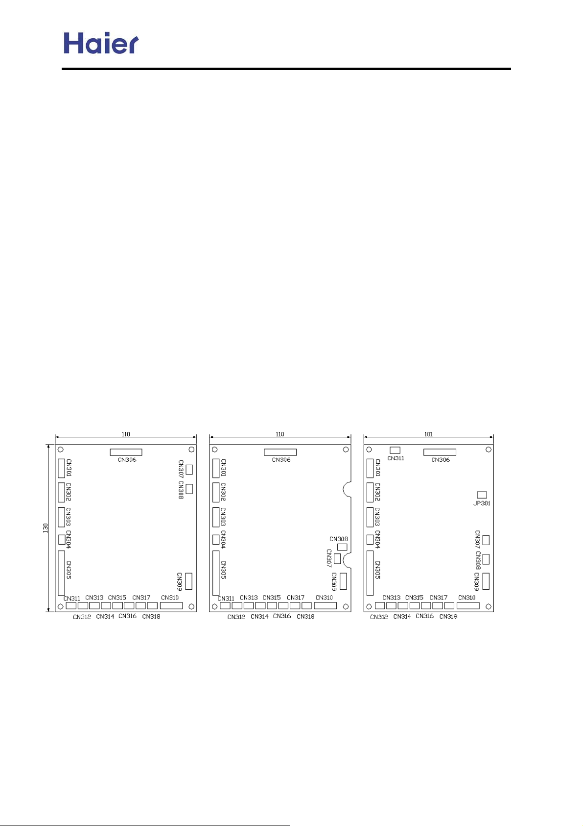
Commercial Air Conditioner Model: AU242FHBIA,
AU482FIBIA, AU48NFIBJA
Below we will comment for the functions of some ports and some changes of PCB
0010451530 and 0010451531:
1. Control Board 0010451530
Herein, the control board we are concerned is the board without CPU. Functions for every port are as
follows:
CN301: port for power supply, connected with CN202 of the power board.
CN302: connected to testing board.
CN303: connected to the computer serial port through the testing device.
CN304: HBUS communication port.
CN305: the driving port for relay, connected to CN203 of the power board.
CN306: the driving port for IPM, connected to CN105 of the power board.
CN307, CN308: port for the heat-emitting fan. No used at present.
CN309: port for the main relay and for testing current, connected to CN104 of the power board.
CN310: the driving port for electronic expansion valve.
CN311: testing port for the radiator temperature. No used at present.
CN312: testing port for the coil temperature Tt.
CN313: testing port for the defrosting temperature Te.
CN314: testing port for the outdoor ambient temperature Ta.
CN315: testing port for the suction temperature Ts.
CN316: testing port for the discharging temperature Td.
CN317: port for the signal of compressor overheat protection initially,but now for low pressure switch.
CN318: port for the signal of high/low pressure protection,but now only for high pressure switch.
Control board 1 Control board 2 Control board 3
Totally there are 3 types of control board, because they have different appearance, you will distinguish them
much easier.
Control board 1 is the earliest edition, because this board is rather big and it will cover the fixing screw
which supports the electric control box, also taken into consideration the convenient installation and service,
we modified and designed the Control board 2.
Control board 2 is the second edition, because there are electric parts on both sides of this board, and
-85-
Page 86
Commercial Air Conditioner Model: AU242FHBIA,
AU482FIBIA, AU48NFIBJA
hard to be installed, we designed the Control board 3.
Contro l boa rd 3: the current edition. Now the part number of control PCB is 0010451971
instead of 0010451530.
The new control board(0010451971) also can be used as 0010451530,but the connector
"OH" must be shorted.
2. Pow er board 0010451531
There are two types of power board, and they have the same dimensions, but have the different voltage
testing parts. That is easy to distinguish.
The newly power board adopts the voltage sensor to test the voltage. On the board there is a black square
type voltage sensor. The old board adopted the LM331 to test the voltage, which is an inserted part IC with
8 feet.
However both the new or old power boards can match any of the control board, but the CPU diagrams are
different.
3. Fil ter board 0010451536
Originally, the electric control box has not any filter board. In order to avoid the exterior interference and
result in the bad communication, the second edition (current edition) are all added the filter board.
-86-
Page 87
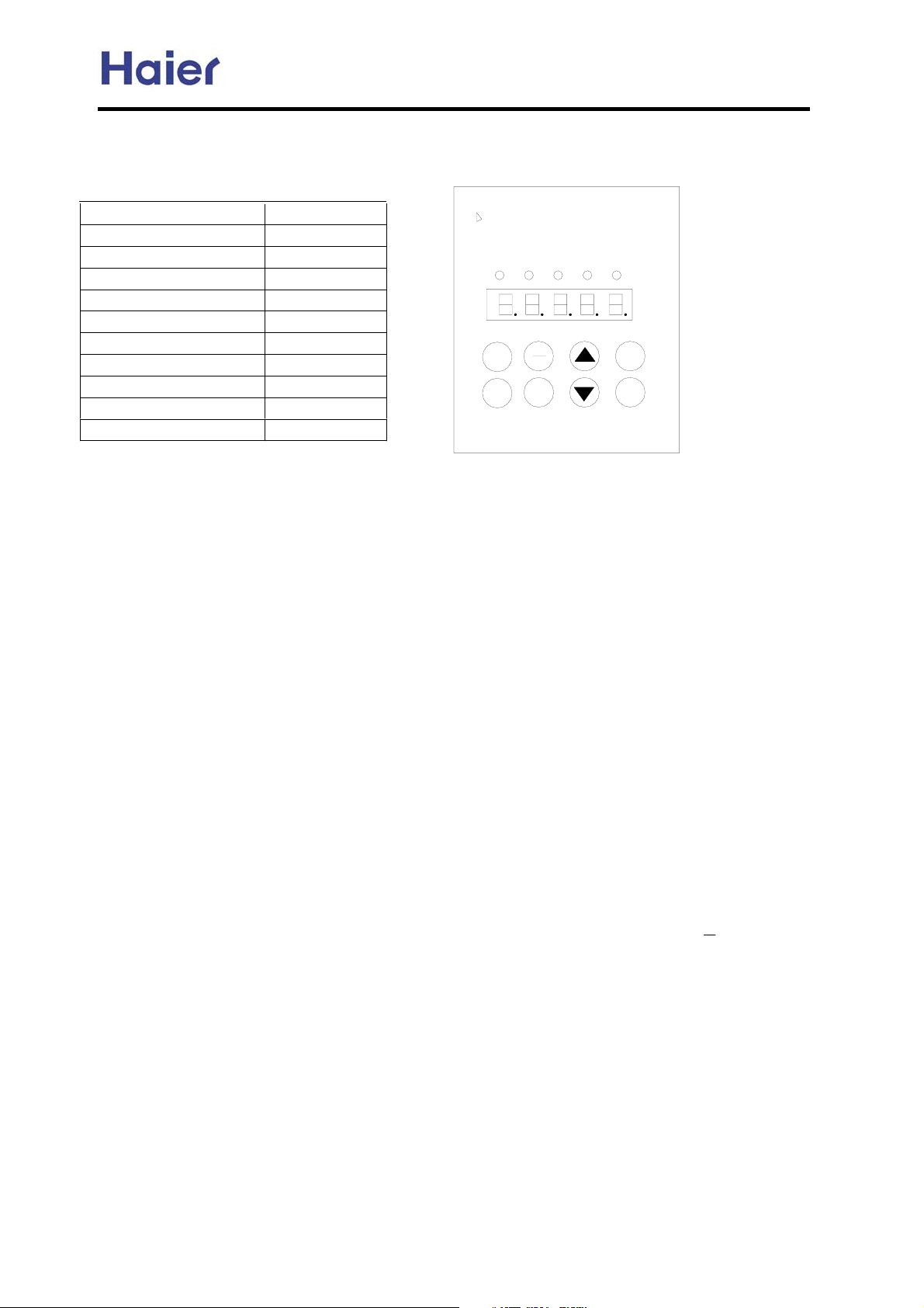
Commercial Air Conditioner Model: AU242FHBIA,
AU482FIBIA, AU48NFIBJA
8.7 Testing board for AU48NFIBJA:
Press button “mode”, the display will change over in the following sequence:
State
Display
Frequency Fxx.xx
Current output A xx.x
5XQ 6WRS 'HIU &RRO +HDW
Voltage on DC side U xxx
Ambient temp 1 xx
Discharging temp 2 xx
Suction temp 3 xx
Defrosting temp 4 xx
Coil temp 5 xx
5XQ
6WRS
&RRO
+HDW
0RGH
3URJ
(QWHU
Indoor unit quantity 6 xx
Open degree of EEV 7 xxx
Note: Please connect the wire on power off. Insert the testing board on the CN302 of the
outdoor PCB. The part number is 0010451601.
In addition, we set a testing port CN303 which can be connected to the computer through
another testing device (part number: 0010451800). The distributor can get the testing device
and the testing software from us.
Testing procedure:
1. After the unit powered off, connect the wire of testing board to CN302 port, and then pull
down the communication wire between outdoor and indoor unit.
2. Check if the wiring is right. If yes, power on the outdoor unit.
3. On the operation panel of the testing board, the relative data can be modified.
4. Press “Prog.”, enter data editing mode.
5. Set data “Pr-00” as “0”ˈthen data can be edited. Press “Enter” to confirm.
6. The other data can be set according to the requirement like this way.
7. After all the data be modified, set “Pr-00” as “1”.
8. Press “Prog.”, quit out of data editing mode.
9. Note: Data of the chip is very important, the improper modification will cause the main
parts damaged such as compressor. So before modification, please contact with us.
10. After quitting from data editing mode, operation board will display “P r.E” which will
flash. After 3 minutes, it will display “b.P.160”. At this time, pressing the
to reset
the program.
11. After reset, power off the outdoor. For 1~2 minutes, the outdoor release all the electricity,
plug the communication wire between outdoor and indoor to the original position, the
modification is over.
-87-
Page 88
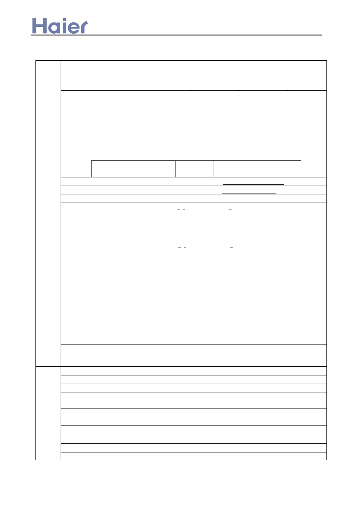
Commercial Air Conditioner Model: AU242FHBIA,
AU482FIBIA, AU48NFIBJA
8.8 AU482FIBHA: function specification of SW01, SW02, SW04, SW05, SW06, SW07
Table 1
SW01 SW02 Display of 7 segments LED (LD1,LD2,LD3)
0
0 FFF shows capability overloading (if capability overloading function is chose)
Outdoor diagnosis code when without diagnosis code, display: - 1 Outdoor running mode cooling: C heating: H defrosting: J
2 Defrosting area set: display 1------shows that L is set at “12”
display 2------shows that L is set at “10”
display 3------shows that L is set at “8”
When the following condition is available, the unit enters into defrosting running:
(TE: defrosting temp., TA: ambient temp.)
TEİChTAˉ¢
Note˖C˖TA˘0ćˈC=0.8
TAı0ćˈC=0.6
The value of ¢ can be set according to the selection of jump wiring:
selection of jump wiring L M H
¢(ć)
4
5
6
7 Back up running: TS sensor: 1 , TE sensor: 1
INV command frequency˄decimalism˅ e.g.120 stands for 120HZ
INV receiving frequency˄decimalism˅ e.g. 84 stands for 84HZ
Quantity of indoor units connected˄decimalism˅ e.g. 6 stands for 6 indoor units
This function is preset and not available.
12e 10e 8e
8 Back up running: TA sensor: 1 , mid-section temp. sensor: 1
This function is preset and not available.
9 Back up running: PD sensor: 1 , PS sensor: 1
This function is preset and not available.
13 Display compensation of capacity class: 4------class 4, 6-----class 6
After the start-up of system is over, the frequency of compressor has gotten the
target frequency confirmed by the request of indoor unit capacity for 5 minutes,
and then the unit will modulate the capacity.
(Note: class 4 and class 6 can be selected. Class 4 is that the capacity class
whose range is from 4 classes higher to 3 classes lower than the target frequency.
Class 6 is that the capacity class whose range is from 6 classes higher to 4
classes lower than the target frequency. For the unit without pressure sensors,
there is no this function.)
14 Display “U” shows that indefinite capacity is chose
Display “d” shows that definite capacity is chose (indoor total capacity can’t be
over 130%˅
15 Display o1-----stands for HP
Display o2-----stands for HP
Display H1-----shows that can be connected with central communication
1
0
1
2
3
4 Mid-section of coil pipe sensor data (decimalism)
5
6
7
8
9
10 Outdoor running current (decimalism)
TD sensor data˄decimalism˅
TA sensor data˄decimalism˅
TS sensor data˄decimalism˅
TE sensor data˄decimalism˅
Pd sensor data˄display corresponding saturation temperature˅
Ps sensor data˄display corresponding saturation temperature˅
Opening degree of outdoor PMV1˄decimalism˅
Opening degree of outdoor PMV2˄decialism˅
2-way valve switched on: SV ON˖
1ˈno switched on: --
-88-
Page 89
˖
˖
˖
˖
˅
p
Commercial Air Conditioner Model: AU242FHBIA,
AU482FIBIA, AU48NFIBJA
11
12
13
14
2
3
4 0—15 Indoor diagnosis code, no diagnosis code: --this function is preset
5 0—15 Indoor HP
6 0—15 Indoor required capacity (decimalism) indoor P-CODE
7 0—15 Indoor PMV opening degree (decimalism)
8 0—15
9 1—16
10 1—16
11 1—16
12 1—16 Single cool trial run--this function is preset
13 1—16 Single heat trial run--this function is preset
0
1
2
3
4 Heat trial run: H --this function is preset
5 Swing trial run: _F--this function is preset
6
7 Clean abnormal function: CL--this function is preset
8
9
10
11 Outdoor rated setting: -F
0—7
8 Display quantity of communicating indoor unit, e.g. : 6 shows that 6 indoor units
Outdoor fan mode :_1˄low speed˅,_2˄med speed˅,_3˄high speed˅
Temperature sensor ON display ON˖
Four-way valve switched on: ON˖
Running mode selection cooling˖
Dispatch line check cooling
Dispatch line check heating
Cool trial run
Indoor unit uniform start/stop
--this function is preset
Outdoor PMV1fully openǃclose function: fully open: FF, fully close: 00
Outdoor PMV2 fully openǃclose function: fully open: FF, fully close: 00
Indoor PMV fully openǃclose function˖fully open: FF
Indoor communication state: receiving normal˖
are working.
new code:0 stands for 0.8HP, 1 stands for 1HP, 2 stands for 1.2HP,
3 stands for 1.5HP, 4 stands for 2HP, 5 stands for 2.5HP, 6 stands for 3HP, 7
stands for 4HP
Old code: 1 stands for 1HP,7 stands for 7HP
Indoor saturation temperature (decimalism) -26.0—67.0˄account according to
outdoor suction pressure PS˅
Indoor sensor TA temperature˄decimalism˅-26.0—67.0
Indoor sensor TC2 temperature˄indoor gas pipe˅˄decimalism˅-26.0—100.0
Indoor sensor TC1 temperature˄indoor liquid pipe˅˄decimalism˅-26.0—100.0
C --this function is preset
1 Four-way valve not switched on: OFF˖_ _
C, heating: H
CC --this function is preset
HH--this function is preset
run: 11/stop: 00˄display -- after 3 minutes
1ˈOFF˖--
1 receiving abnormal:
Combination control with outdoor switches
Table 2
function summary Method of set, cancel
Cool trial run Indoor trial run in cooling
mode, the function is the
same as trial run with remote
controller, the indoor unit
which trials run fixes the temp.
difference as max. temp., and
send it to outdoor, the other
control is similar with normal.
Heat trial run Indoor trial run in heating
mode, the function is the
same as trial run with remote
controller, the indoor unit
which trials run fixes the temp.
difference as max.
[set]
SW01“2”, SW02“03”, press SW04 for more
than 2 seconds, after set of trial run success, LD
will always display –C until the function is
cancelled.
[cancel]
in trial run state, SW01“02”, SW02“03”, press
SW05
[set]
SW01“2”, SW02“04”, press SW04 for more than
4 seconds, after set of trial run success, LD will
always display –H until the function is cancelled.
[cancel]
in trial run state, SW01“02”, SW02“03”,
ress
-89-
Page 90
Commercial Air Conditioner Model: AU242FHBIA,
AU482FIBIA, AU48NFIBJA
temperature, and send it to
outdoor, the other control is
similar with normal.
Swing trial run Indoor trial run in swing
mode,the control is the same
as swing trial run with remote
controller.
Uniform running Indoor is uniform running
The indoor running mode is
corresponding with the setting
or memory of remote
controller.
Uniform stop Indoor uniform stops [set]
Indoor PMV
fully open
compelled
Rated running Set the unit rated running [set]
Outdoor PMV1
fully open,
closed function
Indoor PMV fully open
compelled in 2 minutes
Outdoor PMV1 compelled fully
open or close in 2 minutes
SW05
[set]
SW01“02”, SW02“05”, press SW04 for more than
2 seconds, after set of trial run success, LD will
always display –F until the function is cancelled.
[cancel]
in trial run state, SW01“02”, SW02“05”, press
SW05
[set]
SW01“02”, SW02“05”, press SW04 for more than
2 seconds, after set of trial run success, LD will
display FF for 5 seconds.
[cancel]
cancel according to operation of remote
controller
SW01“02”, SW02“06”, press SW05 for 2
seconds, after set success, LD will display FF for
5 seconds.
[cancel]
cancel according to operation of remote
controller
[set]
SW01“2”, SW02“10”, press SW04 for more than
2 seconds
[confirmation]
in 2 minutes, 7-segment LED of base board I/F
will display “FF” all the time
[cancel]
the control software will recover PMV to normal
open degree after 2 minutes ˄ after indoor
software receives the signal of fully open from
outdoor, PMV will fully open only in 2 minutes.˅
SW01“02”, SW02“11”, press SW05 for more than
2 seconds, after setting success, LD will display
–F, shows that the unit may enter rated running
mode, afterwards you can set SW06,
SW07.SW06 is used for increasing frequency,
while SW07 is used for decreasing frequency.
[cancel]
cancel according to operation of remote
controller
[set]
SW01“3”, SW02“9”, press SW04 for more than 2
seconds
[confirmation]
in 2 minutes, 7-segment LED of base board I/F
will display “FF” all the time
[cancel]
the control software will recover PMV to normal
open degree after 2 minutes ˄ after indoor
software receives the signal of fully open from
outdoor, PMV will fully open only in 2 minutes.˅
-90-
Page 91
Commercial Air Conditioner Model: AU242FHBIA,
AU482FIBIA, AU48NFIBJA
Outdoor PMV2
fully open,
closed function
Outdoor PMV2 compelled fully
open or close in 2 minutes
[set]
SW01“3”, SW02“10”, press SW04 for more than
2 seconds
[confirmation]
in 2 minutes, 7-segment LED of base board I/F
will display “FF” all the time
[cancel]
the control software will recover PMV to normal
open degree after 2 minutes ˄ after indoor
software receives the signal of fully open from
outdoor, PMV will fully open only in 2 minutes.˅
2. Specification for SW03
The two switches of SW03 should be ON or OFF at the same time.
-91-
Page 92
Commercial Air Conditioner Model: AU242FHBIA,
AU482FIBIA, AU48NFIBJA
8.9 Sensor characteristic
model sensor number sensor name sub-sensor number characteristic
R25=10Kȍ±3%
B25/50=3700K±3%
R25=10Kȍ±3%
B25/50=3700K±3%
R25=10Kȍ±3%
B25/50=3700K±3%
R25=10Kȍ±3%
B25/50=3700K±3%
R80=50Kȍ±3%
B25/80=4450K±3%
R25=10Kȍ±3%
B25/50=3700K±3%
R25=10Kȍ±3%
B25/50=3700K±4%
R80=50Kȍ±3%
B25/80=4450K±3%
R25=10Kȍ±3%
B25/50=3700K±4%
R25=10Kȍ±3%
B25/50=3700K±3%
R25=10Kȍ±3%
B25/50=3700K±3%
R25=23Kȍ±2.5%
B25/50=4200K±3%
R25=10Kȍ±3%
B25/50=3700K±3%
AU482FIBIA
AU48NFIBJA
AB092FCBIA
AB142FCBIA
AB182FCBIA
AE072FCBKA
AE092FCBKA
AE122FCBKA
AE142FCBKA
AE182FCBKA
AE242FCBKA
0010450192 outdoor ambient temp. sensor 001A3800082
0010450193 suction temp. sensor 001A3800093
0010450194 defrosting temp. sensor 001A3800093
0010450195 mid-condenser temp. sensor 001A3800093
0010450196 compressor discharging temp. sensor 001A3800096
0010450194 defrosting temp. sensor 001A3800093
0010451328 pipe temp. sensor 001A3800093
0010451511 discharging temp. sensor 001A3800096
0010451513 suction temp. sensor 001A3800093
0010451514 ambiet temp. sensor 001A3800082
0010450699 pipe temp. sensor 001A3900004
0010451327 ambiet temp. sensor 001A3900003
0010450699 pipe temp. sensor 001A3900004
AS072FCBHA
AS092FCBHA
AS122FCBHA
AS142FCBHA
AS182FCBHA
AF092FCBHA
AF122FCBHA
001A3800103 liquid pipe temp. sensor 001A3900004
001A3900059 coil temp. sensor
001A3900003
001A3900004
R25=10Kȍ±3%
B25/50=3700K±3%
1.R25=10Kȍ±3%
B25/50=3700K±3%
2.R25=23Kȍ±2.5%
B25/50=4200K±3%
-92-
Page 93
Commercial Air Conditioner Model: AU242FHBIA,
AU482FIBIA, AU48NFIBJA
R80=50Kȍ±3%
B25/80=4450K±3%
T(ć)
-30 11600 24 536.6
-29 10860 25 511.1 -19 85.72 35 6.68
-28 10170 26 486.9 -18 80.96 36 5.43
-27 9529 27 464 -17 76.51 37 5.6
-26 8932 28 442.3 -16 72.33 38 5.59
-25 8375 29 421.7 -15 68.41 39 5.73
-24 7856 30 402.1 -14 64.73 40 5.52
-23 7372 31 383.6 -13 61.27 41 5.32
-22 6920 32 366 -12 58.02 42 5.12
-21 6498 33 349.3 -11 54.97 43 4.93
-20 6104 34 333.5 -10 52.1 44 4.9
-19 5736 35 318.4 -9 49.4 45 4.58
-18 5392 36 304.1 -8 46.86 46 4.42
-17 5071 37 290.5 -7 44.46 47 4.26
-16 4770 38 277.6 -6 42.21 48 4.11
-15 4488 39 265.3 -5 40.08 49 3.97
-14 4225 40 253.6 -4 38.08 50 3.83
-13 3978 41 242.5 -3 36.19 51 3.7
-12 3747 42 232 -2 34.41 52 3.57
-11 3531 43 221.9 -1 32.73 53 3.45
-10 3328 44 212.3 0 31.14 54 3.33
-9 3138 45 203.2 1 29.64 55 3.22
-8 2960 46 194.5 2 28.22 56 3.11
-7 2793 47 186.3 3 26.4 57 3.11
-6 2636 48 178.4 4 25.61 58 2.9
-5 2489 49 170.9 5 24.41 59 2.81
-4 2351 50 163.7 6 23.27 60 2.72
-3 2221 51 155.9 7 22.2 61 2.63
-2 2099 52 150.4 8 21.18 62 2.54
-1 1984 53 144.2 9 20.21 63 2.49
10 1092 20 12.36 74 1.73
11 1036 21 11.84 75 1.68
12 983.2 22 11.34 76 1.63
13 933.4 23 10.87 77 1.58
14 886.4 24 10.43 78 1.54
15 841.9 25 10 79 1.49
16 800 26 9.59 80 1.45
17 760.8 27 9.21
18 722.8 28 8.84
19 687.3 29 8.48
20 653.8 30 8.15
21 622 31 7.83
22 592 32 7.52
23 553.6 33 7.23
Rnom(Kȍ)
0 1877 54 138.3 10 19.3 64 2.38
1 1775 55 132.7 11 18.43 65 2.3
2 1680 56 127.3 12 17.61 66 2.23
3 1590 57 122.1 13 16.83 67 2.16
4 1506 58 117.2 14 16.09 68 2.09
5 1426 59 112.5 15 15.38 69 2.03
6 1351 60 108 16 14.71 70 1.96
7 1280 61 103.8 17 14.08 71 1.9
8 1214 62 99.68 18 13.48 72 1.85
9 1151 19 12.9 73 1.79
R80=50Kȍ±3%
B25/80=4450K±3%
T(ć)
Rnom(Kȍ)
R25=10Kȍ±3%
B25/50=3700K±3%
T(ć)
-20ć
Rnom(Kȍ)
90.79 34 6.95
R25=10Kȍ±3%
B25/50=3700K±3%
T(ć)
Rnom(Kȍ)
-93-
Page 94
Commercial Air Conditioner Model: AU242FHBIA,
AU482FIBIA, AU48NFIBJA
R25=23Kȍ±2.5%
B25/50=4200K±3%
T(ć)
-20ć
-19ć
-18ć
-17ć
-16ć
-15ć
-14ć
-13ć
-12ć
-11ć
-10ć
-9ć
-8ć
-7ć
-6ć
-5ć
-4ć
-3ć
-2ć
-1ć
0ć
1ć
2ć
3ć
4ć
5ć
6ć
7ć
8ć
9ć
10ć
11ć
12ć
13ć
14ć
15ć
16ć
17ć
18ć
19ć
20ć
21ć
22ć
23ć
Rnom(Kȍ)
281.34
263.56
247.04
231.66
217.35
204.02
191.61
180.04
169.24
159.17
149.77
140.99
132.78
125.11
117.93
111.22
104.93
99.04
93.52
88.35
78.94
74.67
70.65
66.88
63.33
56.86
53.91
51.13
48.51
46.04
43.72
41.52
39.45
35.66
33.92
32.27
30.72
29.25
27.86
26.54
83.5
60
37.5
25.3
R25=23Kȍ±2.5%
B25/50=4200K±3%
T(ć)
24ć
25ć
26ć
27ć
28ć
29ć
30ć
31ć
32ć
33ć
34ć
35ć
36ć
37ć
38ć
39ć
40ć
41ć
42ć
43ć
44ć
45ć
46ć
47ć
48ć
49ć
50ć
51ć
52ć
53ć
54ć
ć
55
56ć
57ć
58ć
59ć
60ć
Rnom(Kȍ)
24.12
21.94
20.94
19.99
19.09
18.23
17.42
16.65
15.92
15.22
14.56
13.93
13.34
12.77
12.23
11.71
11.22
10.76
10.31
23
9.89
9.49
9.1
8.74
8.39
8.05
7.73
7.43
7.14
6.86
6.6
6.34
6.1
5.87
5.65
5.44
5.24
-94-
Page 95
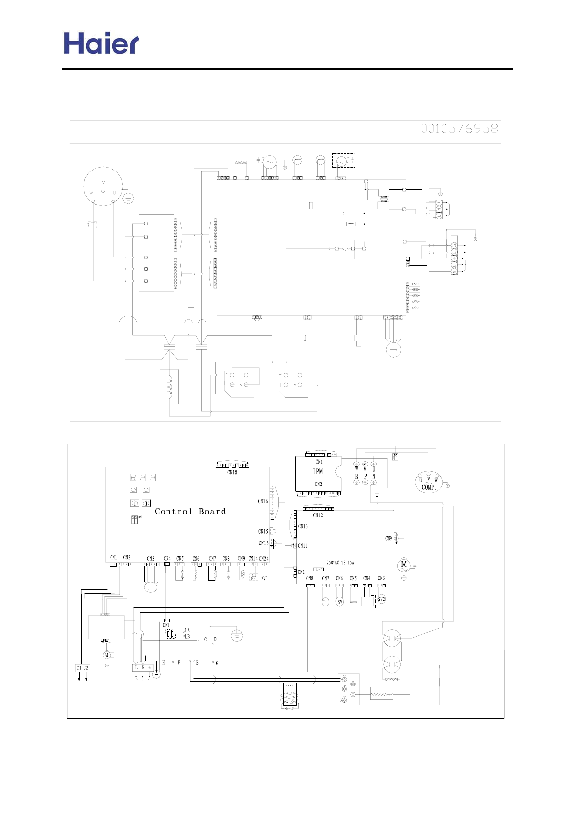
9. Wiring diagram
AU242FHBIA Wiring diagram:
Compressor
CT
B
W
R
BL
P
N
CN101
IPM
U
V
W
CN102
OR
BL
B:Black
BL:Blue
BR:Brown
R:Red
W:White
Y:Yellow
OR:Orange
Y/G:Yellow/Green
Electrolytic
Capacitor
F/400V
2500
ˇ
ˇ
ˉˉ
Reactor
Commercial Air Conditioner Model: AU242FHBIA,
AU482FIBIA, AU48NFIBJA
OUTDOOR UNIT WIRING DIAGRAM
Oxygen
Spray
Y
Electrolytic
Capacitor
100
CN7
CN3
CN2
CN1
F/400V
Crankcase
Heater
CN8
R
B
B
Rectifier
25A/600V
Fan Motor
M
Fan
Motor
Capacitor
CN4
Control Board
CN30
B
4-Way
Valve
CN6
B
High-pressure
Switch
Rectifier
50A/600V
CN16
Generator
Valve
CN22
M
CN23
Parts in dashed fram e are
optional.
CN9
Y/G
W
CN10
L1
F3.15A/250V
PTC
NOCOM
RL1
W
CN34
Low-pressure
Switch
CN11
CN12
CN21
CN13
CN14
CN15
M
Electronic expansion Valve
Y/G
R
R
Discharge Temp. Sensor
B
Power Supply
1PH,220v-230V~,50Hz
Y/G
Connected To Indoor
Communication Wire
Indoor unit
Power Supply
1PH,220v-230V~,50Hz
Defrost Temp. Sensor
Ambient Temp. Sensor
Suction Temp. Sensor
Mid-Condensor Temp.Sensor
AU482FIBIA Wiring diagram:
/'
/'
/'
6:
6:
6:
6:
6:
0
EEV
B
W
Y/G
Tc
W
6HQVRU
7HPSHUDWXUH
3LSH
6HQVRU
CT
B
&
&
AC Motor B
To indoor uint
CN2
CN1
R
R
L
N
Fan
Capacitor
B
W
/
1
Power Supply
Ts
,QKDOH
&RPSUHVVRU
Earthing
B
B
Current
Detecor
Capacitor
AC Motor A
6SUD\
9DOYH
W
R
Fan
Capacitor
Electrolytic
Capacitor
Electrolytic
Capacitor
R
B
1.Parts in dashed
frame are optional
2.B:Black
R:Red
W:White
Y/G:Yellow/Green
Td
6HQVRU
9HQW
Te
&RPSUHVVRU
6HQVRU
7HPS
6ZLWFK
'HIURVW
Y/G
+LJK3UHVVXUH
6ZLWFK
/RZ3UHVVXUH
High Voltage Control
W
B
W
Fuse
4-Way
valve
W
Unloading
Valve
Board
Crankcase
Heater
Oxygen
Generator
Ta
6HQVRU
7HPSHUDWXUH
$PELHQW
W
Rectifier
Reactor
AC Contactor
R
Resistance
B
B
R
-95-
Page 96
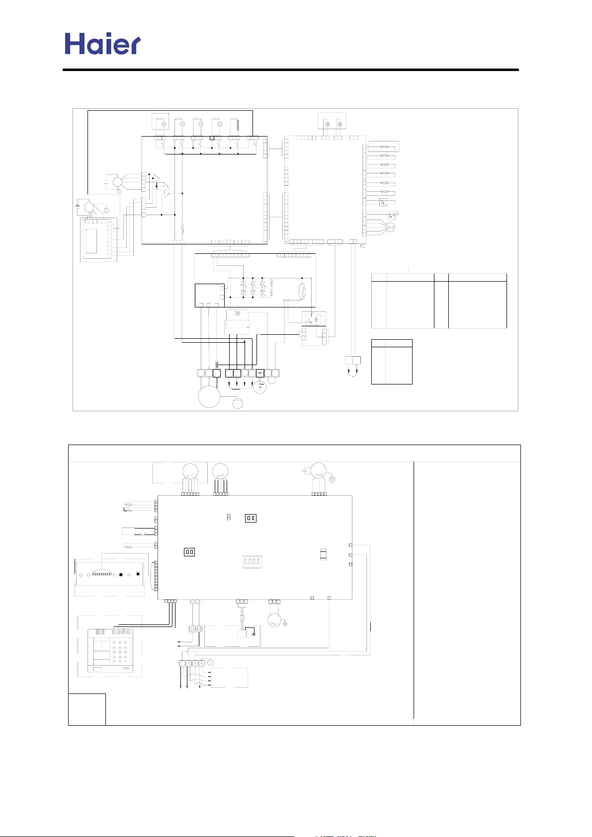
AU48NFIBJA wiring diagram:
Commercial Air Conditioner Model: AU242FHBIA,
AU482FIBIA, AU48NFIBJA
CF2
Fan capacitor
Fan capacitor
FAN2
12345
CN1
SCLD-P-B-4PDT-C
201916 151211 8 7 4 1
201916 151211 8 7 4 1
IPM
UVW
CT
WR
B
CM
CRANKCASE
HEART
CN201
CN103
N
P
(+)
RECTIFIER
(
)()()
Noise Filter
RSTN
Power Supply
Y/G
W-P
RY202
RY201
C101 C102 C103
C104 C105 C106
)
(
CN202
CN203
1
2
3
4
5
1
2
3
4
5
6
7
8
9
10
11
12
13
R101
R114
Lm2Lm1
Y/G
12345 12 2121
1
CN303
2
3
CN301
4
5
1
2
CN302
3
4
5
Control Board
1
2
3
4
5
6
CN305
7
8
9
10
11
12
CN306
13
1234567 89
CN105
PTC
L2
1
2
3
Anti-surge relay
CN107
CN104
CN308 CN307
987654321
RY101
FM4FM3
CN309
123412
1
2
3
4
Communication
JP301
TSINK
1
CN311
2
Tt
1
CN312
2
Te
1
CN313
2
Ta
1
CN314
2
Ts
1
CN315
2
Td
1
CN316
2
0H(L)
1
CN317
2
0P(H)
1
CN318
2
1
2
CN310
3
4
5
CN304
Remarks:
1. CN302 ǃ CN303 areports for
controllers,and will be used in maintenance.
2. Parts in dashed frame are optional.
Symbols meaning
part name
symbol
CM
compressor
FM
fan motor
OX-P
oxygen bar function
4-WAY
4-way valve
SV
solenoid valve
HEAT
crankcase heater
W-P
water pump
TSINK
radiator temp. sensor
mid-condenser temp. sensor
Tt
Color symbol:
symbol symbol
black
B
blue
BL
red
R
C1 C2
W
Y
G
Y/G
white
yellow
green
yellow/green
0010577105
symbol
part name
defrosing temp. sensor
Te
ambient temp. sensor
Ta
suction temp. sensor
Ts
Td
discharging temp. sensor
Low pressure switch
0H
0P
High pressure switch
EEV
Electronic expansion valve
CT
current transducer
4-WAY
OX-P
321 321 123321321213
RY209
5
4
1
5
4
3
2
1
3
2
CN212
RY208
CN204
FAN1
CF1
CN211
1
2
CN3
3
1
2
3
CN2
4
5
SV2 SV1
CN210 CN210 CN208 CN207 CN206 CN205
RY206 RY205 RY204 RY203
Power Supply Board
RY207
T3.15A/250VAC
123
L
N
UVW
AB**2FCBIA wiring diagram:
gas pipe temp. sensor
liquid pipe temp. sensor
Room temp. sensor
LED3
LED4
10
TIMCOMP
B:Black
BL:Blue
BR:Brown
R:Red
W:White
Y/G:Yellow/Green
float switch
5
146
97823
OPER
Remote receiver
Remote control type
Wired controller
A
Wired control type
electronic
expansion valve
Builtin EEV type
emergency
LED1LED2
switch
POW
sw01
BEEP1
B
CD
outdoor
communication
CN5
243
1
2
CN9
1
23
CN11
1
2
CN
1
10
9
8
7
6
CN13
5
4
3
2
1
CN14
3214
ac
b
d
W
indoor power
1PH.220-230V~.50Hz
sw03
BR
M
423156
CN6
CN1
1
2
R
Indoor unit wiring diagram
fan capacitor
serial
CN16
M
swing motor
32145
CN3
sw02
2
1
Indoor control board
sw01
unit code setti ng
1
Outside EEV type
CN7
1
23
M
pump motor
CN4
R
32
negative ion generator or high
voltage accumulator
<*
electronic
expansion valve
box power supply
and communication
Must connect electronic expansion valve box
NOTE
˖
power and communication from corresponding
indoor,wiring sequence must correspond with
the label respectively,other wise, will cause
PCB of indoor and electronic expansion valve
box not work and damaged.
T3.15A/250VAC
FUSE
CN19
M
5
4
CN8
123
CN20
fan motor
CN25
CN18
CN22
0010577029
About the PCB setting
In the diagram,gas pipe temp. sensor,liquid pipe temp.
sensor,room temp.sensor ,indoor fan motor,float switch,
pump motor,swing motor are
controller,remote receiver,electronic
Wired
valve
are parts matched with
negative ion generator or
are optional parts for health
Wired controller and remote receiver
one of type at will.
The setting of SW01,SW02 and SW03 :
1.The former three bits of SW01 are used to set unit
number,which are operated by the installer on field .
2.The fourth bit of SW01 is used to choose different
indoor fan speed in heating mode."ON"means that fan
speed can be set as middle and low level,"OFF"means
that fan speed can be set as high,middle and low level.
3.The first bit of SW02 and SW03 is used to choose
wired control type or remote control type.
"ON"means that the unit with wired controller(other parts
are as the same as remote control unit). And "OFF"is
remote controller.
The unit with wired controller
on wired controller with remote controller such
4.The second bit of SW02 is used to choose built-in or
outside electronic expansion valve setting .
"ON"means built-in type :
expansion valve
"OFF"means outside type:
electronic expansion valve communication,and the
expansion valve box(MP3A) control indoor
Attentions:
The CN9 is
is must be set "ON",And CN19,CN22 is not available.
CN16 is a serial communication port for service.
The dip switch setting when out of factory
necessary parts;
the model(combined usage);
high voltage accumulator
and comfort
CN6 is connected with
and indoor unit control
CN25 is connected with
So the second bit
not available .
expansion
combined
˄
only can be chosen
can make remote operation
as YR-H71 .
electronic
refrigerant flow itself.
electronic
refrigerant flow.
of SW03
usage).
-96-
Page 97
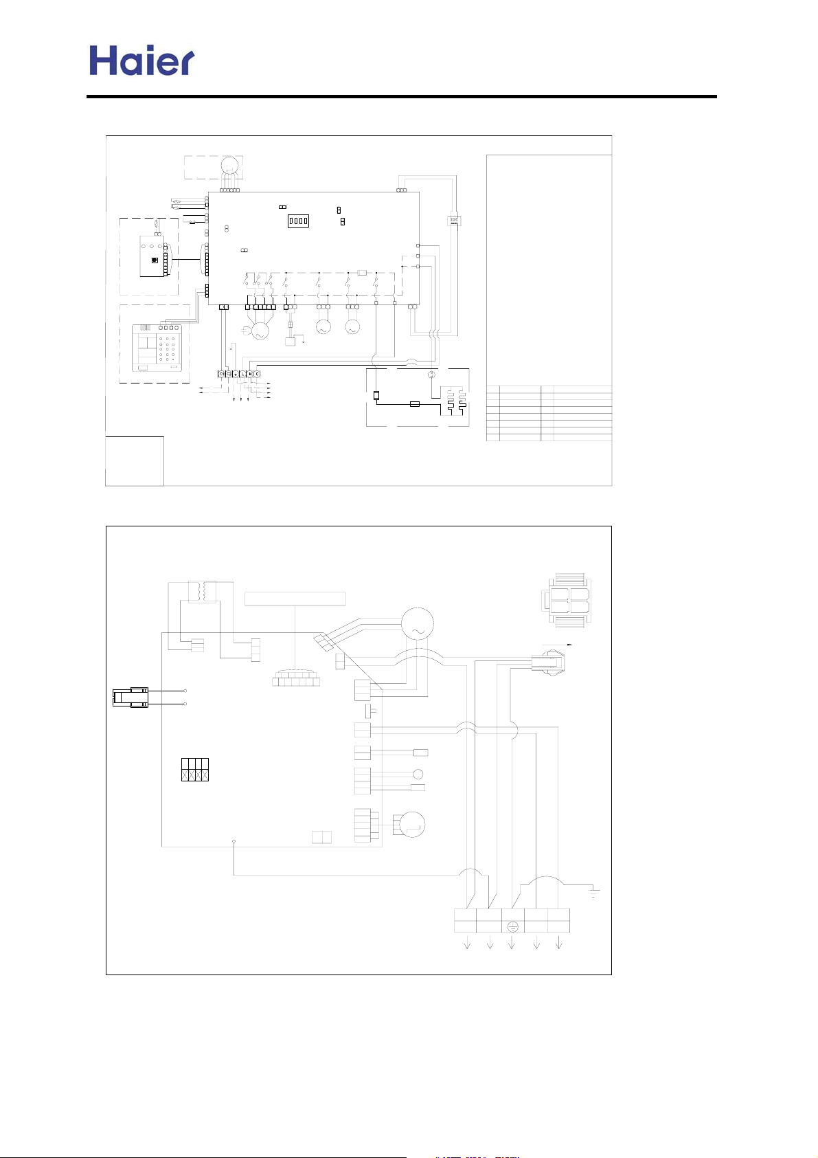
AE**2FCBKA wiring diagram:
Commercial Air Conditioner Model: AU242FHBIA,
AU482FIBIA, AU48NFIBJA
electronic
M
gas pipe temp. sensor
liquid pipe temp. sensor
ambient temp.
sensor
receive display PCB
choice of remote
controller type
choice of wired
controller type
wired controller
B:Black
BL:Blue
BR:Brown
R:Red
W:White
Y/G:Yellow/Green
expansion valve
float switch
indoor temp
21
sensor
CN2
10
9
LED1LED2LED3
78
SW1
5
3
2
CN1
146
BACD
outdoor
communication
43
CN5
2
23
CN11
11
2
CN24
10 1
9
8
7
6
CN13
5
4
2
1
4 3
3
CN14
2
1
RR
423156
CN6
2
serial
1
CN16
CN15
2
RL7
CN1 CN10
1
fan
capacitor
Y/G
indoor power
1PH.220-230V~.50Hz
for built-in EEV type
Indoor control board
1
RL6 RL5
CN4
6
5
72
43213
M
indoor fan motor
negative ion generator or
high voltage accumulator
electronic
expansion valve
box power supply
and communication
Must connect electronic ex pansion valve box
NOTE˖
power and communication from c orresponding
indoor,wiring sequence mus t correspond with
the label respectively,ot her wise, will cause
PCB of indoor and electroni c expansion valve
box not work and damaged.
AS**2FCBHA wiring diagram:
Indoor unit wiring diagram
TRANSFORMER
Display Bar
CN11
R
W
XB1
XB2
CN10
CN1
Control Board
SW01
ON
OFF
water
CN9
sensor
2
1
unit code setting
RL4
1
2
connector
earthing
CN6
temperate
RL3 RL2
CN7 CN12
23132
MM
CN2
CN13
CN12
CN14
CN7
CN8
CN5
CN17
1
2
CN23
SW2
1
2
swing motorpump motor
BL BL
1
CN8
FUSE
T3.15A/250VAC
RL1
CN19
CN20
1
resumable heat
protector
80 10A/250VACćˈ
FUSE
T15A/250VAC
one-off heat protector
105ćˈ10A/250VAC
only applicable for unit with
auxiliary electric heater
FAN MOTOR
EMERGENCY SWITCH
LIQUID PIPE TEMP.
SENSOR
ROOM TEMP. SENSOR
GAS PIPE TEMP.
SENSOR
STEPPING MOTOR
32
transformer
CN25
BR
CN18
W
CN22
CN3
21
RRB
auxiliary heater
M
TO
ELECTROMAGNETIC
VALVE BOX
M
0010573324
NOTE:The dashed "
PCB inner wiring.
About control board outer connector:
In the diagram,gas pipe temp. sensor,liquid pipe
temp. sensor,indoor fan motor,transformer are
necessary parts
display,electronic expansion val ve,float
switch,pump motor,swing motor are parts matched
with the model(combin ed usage˅˗
electric heater,negative ion generator,high voltage
accumulator are optional parts for health and
comfort
controller and receive display only can choose one
at will.
The unit with remote controller is matched with
receive display:
1.Ceiling concealed type:CN11 must be short
2.Duct type˖connected with float switch and
3.Cassette type:connected with float switch
4.Cabinet type:CN11 must be short connected
The unit with wired controller(equipped with wired
controllerˈ
controller with remote controller such as YR-H39)
Short connect CN15
wireˈ
Setting method with electronic expansion valve outside:
CN23 is disconnected,CN25 is connected with electronic
expansion valve communication,and the electronic
expansion valve box(MP3 or MP2) control indoor
refrigerant flow.
Setting method with built-in electronic expansion valve:
connected with electronic expansion valve
indoor unit control refrigerant flow itself.
Attentions: The water temp sensor (CN9) and indoor
temp sensor (CN24) are unus eful now. The fourth bit
of 4 position dial switch is used to choose the
different speed of indoor fan under heating mode.
"ON" means that the speed of indo or can be choosed
from middle and low."OFF" means that the speed of
indoor fan can be choosed from high,middle and low.
CN23
CN15
CN17
CN16
CN11
LED3
LED2
LED1 RL1
ˉˉˉ"in indoor controll board is
˗Wired controller,receive
combination usage arbitrarily).Wired
˄
connected with a jump wire
pump motor
pump motor and swing motor˗
with a jump wireˈ
can make remote operation on wired
other parts are the same as remote control unit
CN23 is short connected with a jump wire, CN6 is
short connector for built-in
electronic expansion valve
short connector for wired
controller
serial communication port
connector for float switch
indicator˄runningˉred˅
indicator
˄timerˉyellow˅
indicator˄powerˉgreen˅
˗
˗
connected with swing motor
CN17 together with jump
ǃ
emergency switch(ON/OFF)
SW1
indoor fan motor low-speed relay
RL7
indoor fan motor Mid-speed relay
RL6
RL5
indoor fan motor High-speed relay
health function module relay
RL4
pump motor relay
RL3
swing motor relay
RL2
auxiliary eletric heater relay
Auxiliary
˖
and
ˈ
0010573625
VIEW A
1
R
W
B
Y/G
ǃ
24
VIEW A
˗
˖
3
R: RED
B: BLACK
W: WHITE
BL: BLUE
BR: BROWN
Y/G: YELLOW/GREEN
Note:
1.SW01 is the dip switch to set
unit number.
2CN6 is a serial port for some
device.
W
N
Power Supply
1PH,220-230v~,50Hz
-97-
B
Earthing
Wire
EARTHING
C2C1Y/G
RRL
Communication
Wire
Page 98
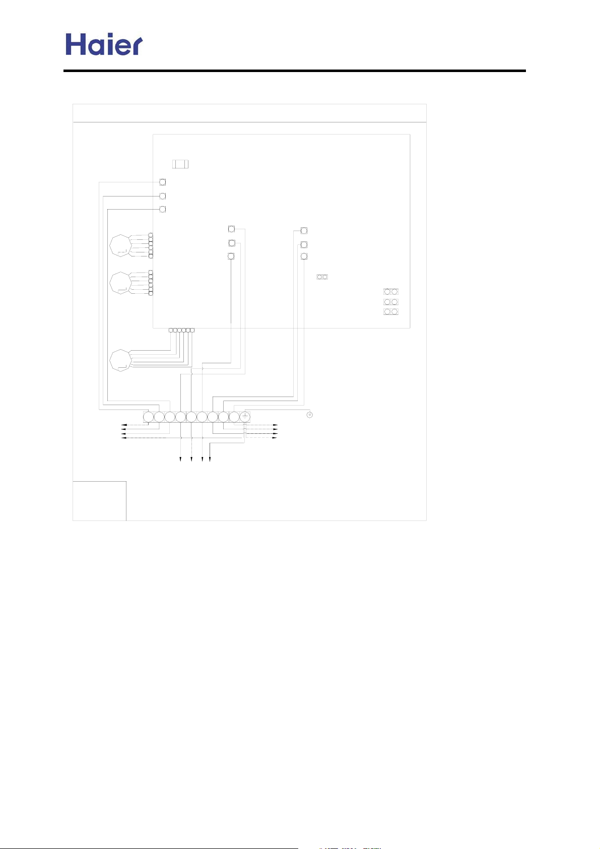
MP3A wiring diagram:
Commercial Air Conditioner Model: AU242FHBIA,
AU482FIBIA, AU48NFIBJA
electronic
expansion
valve3
M
electronic
expansion
valve2
M
electronic
expansion
valve1
M
6
5
4
3
2
1
6
5
4
3
2
1
MP3A wiring diagram
FUSE T3.15A/250VAC
CN1
CN2
CN3
CN15
CN14
CN13
4
65
3
1
2
Control board
CN4
CN5
CN6
CN7
CN8
CN9
1
2
CN6
0010577068
SERIAL
CN10
CN11
CN12
indoor 1
B:Black
BR:Brown
W:White
Y/G:Yellow/ Green
BWBRBWBRBW
L1 N1C1L2 N2C2L3 N3
BR
C3
Y/G
indoor 3
indoor 2
NOTE: Power supply and communicat ion wire must be connected with the corresponding indo or units.Wiring sequence must be
correspondent respectively,L and N must not be conn ected reversely,otherwise, it will cause the unit not work and demaged.
On running, "indoor 1" must be electrified alwa ys, or air conditioner does not work normally.When the system is equipped with MP2A,
the installer should use the corresponding two-way el ectronic expansion valve communication wiring and its driver port
.
-98-
Page 99
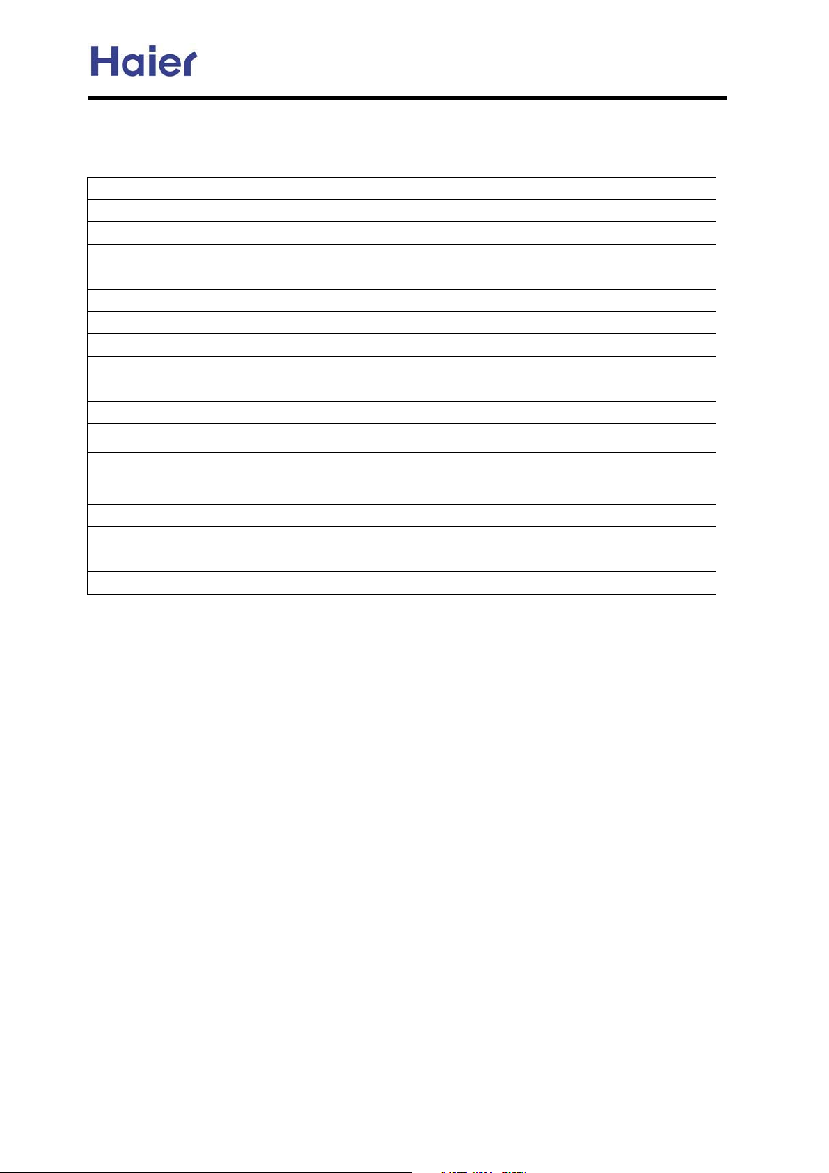
Commercial Air Conditioner Model: AU242FHBIA,
AU482FIBIA, AU48NFIBJA
10. Failure code and troubleshooting
10.1 Outdoor failure code:
AU242FHBIA, AU482FIBIA: check indoor mainboard LED1 or outdoor mainboard LED1.
Failure code Failure description
01 Outdoor defrosting temperature sensor TE circuit failure
02 Ambient temperature sensor TA circuit failure
03 Suction temperature sensor TS circuit failure
04 Discharging temperature sensor TD circuit failure
05 Outdoor mid-condenser temperature sensor failure
06 Over current abnormal
07
09 IPM protection
10 EEPROM on PCB incorrect
11 Discharging temperature protection action
13 Pressure switch circuit abnormal
14 Pressure switch circuit abnormal
Current
mutual inductor failure
19 Discharging temperature protection action when in low frequency
20 Communication abnormal when chip 857 receives signal from chip 846
21 Compressor over current failure
22 Communication abnormal when chip 846 receives signal from indoor unit
23 Chip 846 EEPROM/chip 857 EEPROM failure
-99-
Page 100
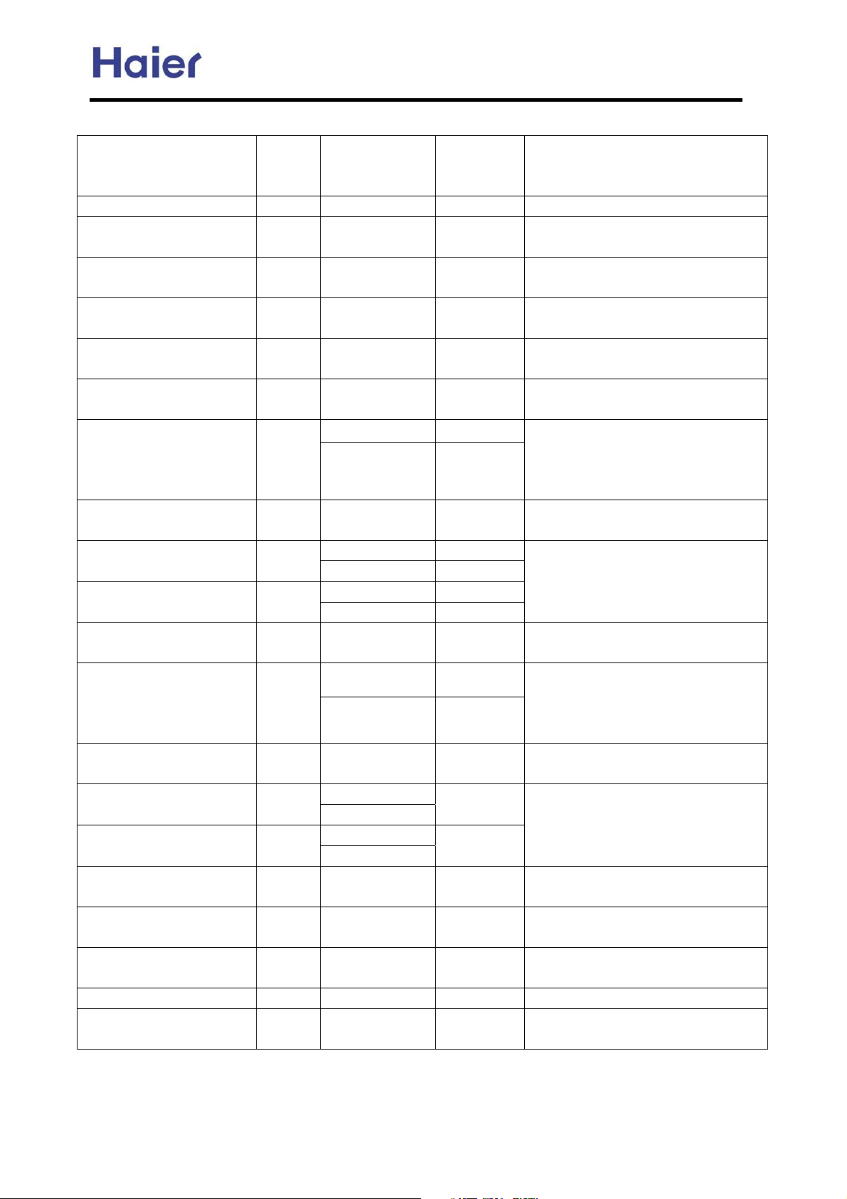
Commercial Air Conditioner Model: AU242FHBIA,
AU482FIBIA, AU48NFIBJA
AU48NFIBJA malfunction code:
LED display on
Malfunction description Code
Normal 0 Normal Yes
Defrosting temperature
sensor abnormal
Ambient temperature sensor
abnormal
Suction temperature sensor
abnormal
Discharging temperature
sensor abnormal
Coil temperature sensor
abnormal
Over current protection 6
Current sensor abnormal 7 C.T.
Overload protection 8
IPM protection 9
Read EEPROM value
wrongly
Discharging temperature
over high abnormal
High pressure switch
abnormal
Voltage over low protection 13
Voltage over high protection 14
Compressor overheat
protection
Recover the parameter set
when out of factory
Clear the malfunction
memory
Need reset 18 P r.E. no Need reset and restart
Radiator temperature sensor
abnormal
1 E.4.
2 E.1.
3 E.3.
4 E.2.
5 E.5.
10 P E.E.
11
12 O.P.
15 O.H.
16 P I.A.
17 P C.T.
-- --
the regulating
board
O.C.
P O.C. no
O.L. Yes
P O.L. no
E.P. Yes
P E.P. no
O.D. Yes
P O.D. no
L.U.
P L.U.
O.U.
P O.U.
If sent to
indoor unit?
Yes
Yes Resumable
Yes Resumable
Yes Resumable
Yes Resumable
Yes
Yes After trouble shooting, need powered off
no
Yes
Yes
Yes
Yes
no
no Need reset and restart
No use
temporarily
Remarks
Resumable
After there are current malfunction for 3
times in 1 hour, the testing board will
display the last abnormal reason P X.X.
Need powered off and restart
and restart
After there are current malfunction for 3
times in 1 hour, the testing board will
display the last abnormal reason P X.X.
Need powered off and restart
Need reset and restart
After there are current malfunction for 3
times in half an hour, the testing board
will display the last abnormal reason P
X.X. Need powered off and restart
Resumable
After there are voltage malfunction for 3
times in 1 hour, the testing board will
display the last abnormal reason P X.X.
Need powered off and restart
Resumable
Need reset and restart
-100-
 Loading...