

Page 1

Page 2

CONTENTS
CAUTIONS
SAFETY PRECAUTIONS
FEATURES AND FUNCTIONS
NAME OF PARTS
INTRODUCTION TO SPARE PARTS
INSTALLATION
REMOTE CONTROLLER OPERATION
GUIDE TO OPERATION
CLEANING AND CARE
TROUBLE SHOOTING
..........................................................................
.....................................................
............................................
...................................................................
.................................
......................................................................
................................................
................................................
..................................................
1-2
6-7
...............................
10-17
18-19
20-21
3
4
5
8
9
OPERATIONG TIPS
.............................................................
22
Page 3
CAUTIONS
Disposal of the old air conditioner
Before disposing an old air conditioner that
goes out of use, please make sure it's
inoperative and safe. Unplug the air
conditioner in order to avoid the risk of
child entrapment.
It must be noticed that air conditioner
system contains refrigerants, which require
specialized waste disposal. The valuable
materials contained in a air conditioner can
be recycled. Contact your local waste
disposal center for proper disposal of an
old air conditioner and contact your local
authority or your dealer if you have any
question. Please ensure that the pipework
of your air conditioner does not get
damaged prior to being picked up by the
relevant waste disposal center, and
contribute to environmental awareness by
insisting on an appropriate, anti-pollution
method of disposal.
Disposal of the packaging of your new
air conditioner
All these valuable materials may be taken to
a waste collecting center and used again after
adequate recycling.
Consult your local authorities for the name
and address of the waste materials collecting
centers and waste paper disposal services
nearest to your house.
Safety Instructions and Warnings
Before starting the air conditioner,
read the information given in the
User's Guide carefully. The User's
Guide contains very important
observations relating to the assembly ,
operation and maintenance of the air
conditioner.
The manufacturer does not accept
responsibility for any damages that
may arise due to non-observation of
the following instruction.
Damaged air conditioners are not to be
put into operation. In case of doubt, consult
your supplier.
All the packaging materials employed in
the package of your new air conditioner
may be disposed without any danger to the
environment.
The cardboard box may be broken or cut
into smaller pieces and given to a waste
paper disposal service. The wrapping bag
made of polyethylene and the polyethylene
foam pads contain no fluorochloric
hydrocarbon.
Use of the air conditioner is to be carried
out in strict compliance with the relative
instructions set forth in the User's Guide.
Installation shall be done by professional
people, don't install unit by yourself.
1
Page 4
CAUTIONS
For the purpose of safety, the air
conditioner must be properly grounded in
accordance with specifications.
Always remember to unplug the air
conditioner before opening inlet grill.
Never unplug your air conditioner by
pulling on the power cord. Always grip
plug firmly and pull straight out from the
outlet.
All electrical repairs must be carried out
by qualified electricians. Inadequate repairs
may result in a major source of danger for
the user of the air conditoiner.
Do not damage any parts of the air
conditioner that carry refrigerant by
piercing or perforating the air conditioner's
tubes with sharp or pointed items, crushing
or twisting any tubes, or scraping the
coatings off the surfaces. If the refrigerant
spurts out and gets into eyes, it may result
in serious eye injuries.
Specifications
The refrigerating circuit is leak-proof.
When installation in under ceiling, dial
switch "K1" in the PC board to "D"
position. When installation in floor
console, dial switch to "L" position (Brand
new unit is in "D" position).For series 14,
18.
D
L
K1
For series 14,18, the all-pole disconrexion connection method should be
applied in the power supply.
For series 24,28,36,42,the breaker of
the air conditioner should be all-pole
switch;and the distance between its two
contacts should be no less 3mm.
Such means for disconnection must be
incorporation in the fixed wiring.
Do not obstruct or cover the ventilation
grille of the air conditioner. Do not put
fingers or any other things into the
inlet/outlet and swing louver.
Do not allow children to play with the air
conditioner. In no case should children be
allowed to sit on the outdoor unit.
2
Page 5
SAFETY PRECAUTIONS
WARNING!
For series 14,18, if the power supply cord of this air conditioner is damaged, it must be replaced by
the manufacturer its authorized service personnel only.
For series 24,28,36,42, the breaker of the air conditioner should be all-pole switch; and the distance between its
two contacts should be no less 3mm. Such means for disconnection must be incorporation
Use copper wire only. All the cables shall have got the European authentication certificate.
For series 14,18, the power supply connects from the indoor side.
For series 24,28,36,42, the power supply connects from the outdoor side. The power cable and connecting
cable are self-provided.
The parameter of connecting cable:
For AC182ACABA, AU182AFABA, (HCFU-18HC03), AC142ACAAA,AU142AFAAA(HCFU-14H03),
AC142ACBAA, AU142AFBAA, (HCFU-14H03/R1)
For AC182ACMBA, AU182AFMBA, (HCFU-18CC03), AC184ACMAA, AU184AFMDA (HCFU-18C13),
AC182ACNBA, AU182AFNBA, (HCFU-18CA03/R1), AC142ACMAA, AU142AFMAA(HCFU-14C03),
AC142ACNAA,AU142AFNAA,(HCFU-14C03/R1).
For series 24,28,36,42, H05RN-F 4G 0.75mm2. The power cable and connecting cable are self-provided.
The requirement of the corss section area of the power supply cord:
For series 14,18, H07RN-F 3G 2.5mm2.
For series 24,28(Power supply:1PH,220-230V~,50Hz), H07RN-F 3G 4.0mm2.
For series 28(Power supply:380-400V,3N~, 50Hz), 36,42, H07RN-F 5G 2.5mm2.
H05RN-F 4G 0.75mm2, H07RN-F 2x2.0mm2.
H07RN-F 3G 2.0mm2 .
DANGER!
in the fixed wiring.
Do not attempt to install this air conditioner by yourself.
This unit contains no user-serviceable parts. Always consult authorized service personnel for repairs.
When moving, consult authorized service personnel for disconnection and installation of the unit.
Do not become excessively chilled by staying for lengthy periods in the direct cooling airflow.
Do not insert fingers or objects into the outlet port or intake grills.
Do not start and stop air conditioner operation by connecting and disconnecting the power supply cord and so on.
Take care not to damage the power supply cord.
In the event of a malfunction (burning smell, etc.), stop operation immediately, turn off the circuit breaker,
and consult authorized service personnel.
CAUTION!
Provide occasional ventilation during use.
Do not direct air flow at fireplaces or heating apparatuses.
Do not climb on place objects on the air conditioner.
Do not hang objects from the indoor unit.
Do not set flower vases or water containers on top of the air conditioner.
Do not expose the air conditioner directly to water.
Do not operate the air conditioner with wet hands.
Do not pull power supply cord.
Turn off power source when not using the unit for extended periods.
Check the condition of the installation stand for damage.
Do not place animals or plants in the direct path of the air flow.
Do not drink the water drained from the air conditioner.
Do not use in applications involving the storage of foods, plants or animals, precision equipment, or art works.
Do not apply any heavy pressure to radiator fins.
Operate only with air filters installed.
Do not block or cover the intake grill and outlet port.
Ensure that any electronic equipment is at least one metre away from either the indoor or outdoor unit.
Avoid installing the air conditioner near a fireplace or other heating apparatuses.
When installing the indoor and outdoor unit, take precautions to prevent access to infants.
Do not use inflammable gases near the air conditioner.
3
Page 6
FEATURES AND FUNCTIONS
AUTOMATIC OPERATION
COOLING TYPE
Merely press the ON/OFF button, and the unit will begin automatic operation in the Cooling
or dry modes as appropriate, in accordance with the thermostat setting and the actual temperature
of the room.
HEAT & COOL TYPE
Merely press the ON/OFF button, and the unit will begin automatic operation in any of the
Heating, Cooling and Blow modes as appropriate, in accordance with the thermostat setting and
the actual temperature of the room.
SLEEP
COOLING TYPE
When the SLEEP button is pressed during Cooling or Dry mode, the thermostat setting
gradually rises during the period of operation. When the set time is reached, the unit
automatically turns off.
HEAT & COOL TYPE
When the SLEEP button is pressed during Heating mode, the air conditioner's thermostat
setting gradually lowers during the period of operation; When the set time is reached, the
unit automatically turns off.
WIRELESS REMOTE CONTROL UNIT
The WIRELESS REMOTE CONTROL UNIT allows convenient control of air conditioner
operation.
MILDEW-RESISTANT FILTER
The AIR FILTER has been treated to resist mildew growth, thus allowing cleaner use and
easier care.
4
Page 7
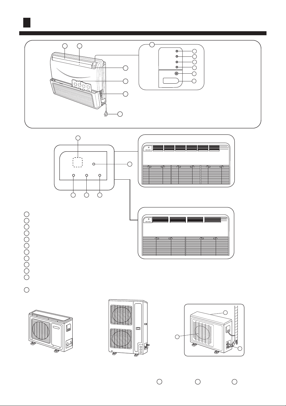
NAME OF PARTS
1110
Fig.1
for series 14,18
3
EMER
POWER OPER
4
TIMER
5 6
Fig.1 Indoor Unit
1 Operating Control Panel (Fig.2)
2 Emergency switch
3 Remote Control Signal Receiver
4 Power Indicator Lamp (Red)
5 OPERATION Indicator Lamp (Green)
6 TIMER Indicator Lamp (Yellow)
7 Compressor Run Lamp (Green)
8 Intake Grill (Fig.3)
9 Air Filter
10
UP/DOWN Air Direction Flaps
11
RIGHT/LEFT Air Direction Louvers
(behind UP/DOWN Air Direction Flaps)
12
Power Plug
1
POWER
OPER
TIMER
3
9
8
12
Fig.2
COMP
EMER
4
5
6
7
2
3
Fig.3
2
for series 36,42
Fig.3
for series 24,28
For series 24,28
Fig.4
14
13
For series 36,42 For series 14,18
Fig.4 Outdoor Unit
13
Intake grill 14 Outlet grill 15 Pipe Unit
5
15
Page 8
INTRODUCTION TO SPARE PARTS
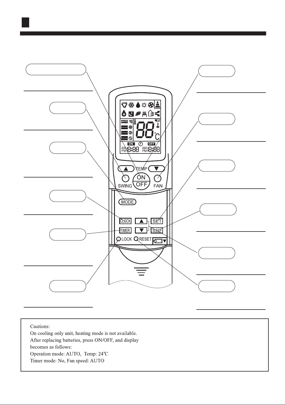
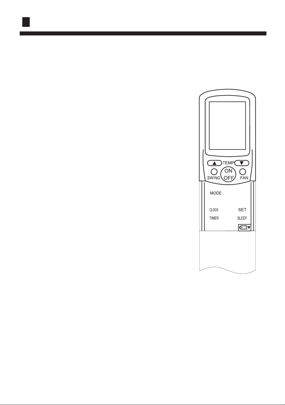
Operation
Power ON/OFF
Used for unit start and
stop.
SWING
Used to set auto fan
direction.
MODE
Used to select AUTO run,
COOL,DRY,HEAT and
FAN operation.
CLOCK
Used to set correct time.Used to set correct time.
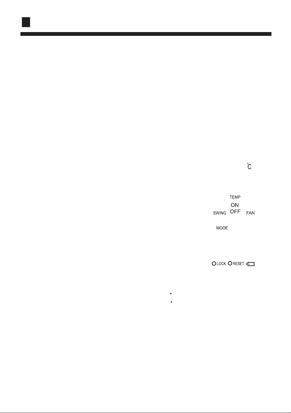
Buttons and display of the remote controller.
TEMP
Used to select your
desired temp.
FAN
Used to select fan speed:
LO, MID, HI, AUTO
SET
Used to confirm Timer
and Clock settings.
SLEEP
TIMER
Used to select
TIMER ON, TIMER OFF,
TIMER ON/OFF.
LOCK
Used to lock buttons
and LCD display.
Used to select sleep
mode.
HOUR
Used to set clock and
timer setting.
RESET
Used to reset the controller
back to normal condition.
Note:
1. The above information is theexplanation of the
displayed information therefore varies
with those displayed in actual operation.
2. This type only has the relevant function and
display as indicated in the above figure.
6
Page 9
INTRODUCTION TO SPARE PARTS
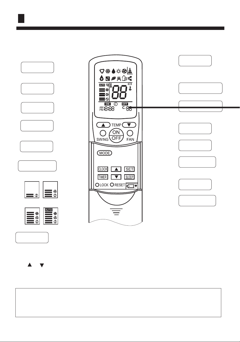
Operation
DRY
AUTO
COOL
SLEEP
SWING
FAN SPEED
LO
MID
Buttons and display of the remote controller.
HEAT
SIGNAL SENDING
FAN OPERATION
LOCK
TEMP.
TIMER OFF
CLOCK
HI AUTO
Clock set
When unit is started for the first time and after replacing batteries in remote controller,
clock should be adjusted as follows:
Press CLOCK button, "AM" or "PM" flashes.
Press or to set correct time. Each press will increase or decrease 1min. If the
button is kept depressed, time will change quickly.
After time setting is confirmed, press SET, "AM "and "PM" stop flashing, while clock
starts working.
Hints
After replacing with new batteries, remote controller will conduct self-check, displaying
all information on LCD. Then, it will become normal.
7
TIMER ON
Page 10
INSTALLATION
Please ask the dealer or specialist to install, never try by the users themselves. After the installation please
be sure of the following conditions.
WARNING !
Please call dealer to install the air-conditioner.
Incorrect installation may cause water leaking, shock and fire hazard.
CAUTION !
Air-conditioner can't be installed in the environment with inflammable gases because the
inflammable gases near to air-conditioner may
cause fire hazard.
Installed electrical-leaking circuit breaker.
It easily cause electrical shock without circuit
breaker.
[Location]
Air-conditioner should be located in well-vented
and easily-accessible place.
Air-conditioner should not be located in the
following places:
(a) Places with machine oils or other oil vapours.
(b) Seaside with high salt content in the air.
(c) Near to hot spring with high content of sulfide
gases.
(d) Area with frequent fluctuation of voltage e.g.
factory, etc.
(e) In vehicles or ships.
(f) Kitchen with heavy oil vapour or humidity.
(g) Near to the machine emitting electric-magnetic
waves.
(h) Places with acid, alkali vapuor.
TV, radio, acoustic appliances etc are at least 1 m
far away to the indoor unit, outdoor unit, power
Connect earthing wire.
Earthing wire should not be connected to the gas pipe, water pipe,
lightning rod or phone line, incorrect earthing may cause shock.
Use discharge pipe correctly to ensure efficient
discharge.
Incorrect pipe use may cause water leaking.
supply wire, connecting wire, pipes, otherwise
images may be disturbed or noises be created.
As required, take measures against heavy snow.
Earthing
[Wiring]
Air-conditioner should be equipped with special
power supply wire.
[Operating noise]
Choose the following locations:
(a) Capable of supporting air-conditioner weight,
don't increase operating noise and vibration.
(b) Hot vapour from outdoor unit outlet and ope rating noise don't disturb neighbour.
No obstacles around the outdoor unit outlet.
8
Page 11
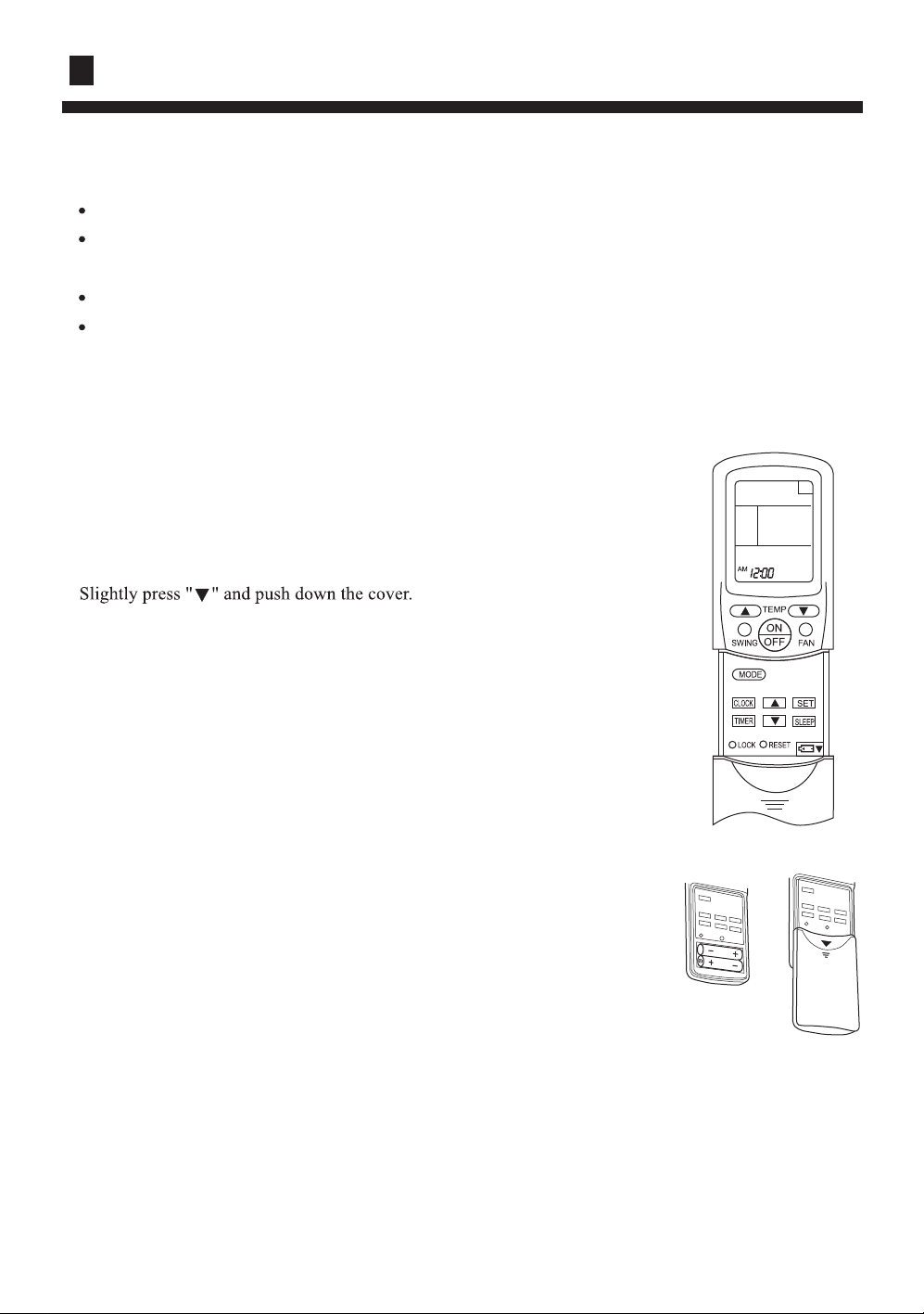
REMOTE CONTROLLER OPERATION
Remote controller's operation
When in use, put the signal transmission head directly to the receiver hole on the indoor unit.
The distance between the signal transmission head and the receiver hole should be within 7m
without any obstacle as well.
Don't throw the controller, prevent it from being damaged.
When electronic-started type fluorescent lamp or change-over type fluorescent lamp or wireless
telephone is installed in the room, the receiver is apt to be disturbed in receiving the signals so
the distance to the indoor unit should be shorter.
Loading of the battery
Load the batteries as illustrated.
2R-03 batteries, resetting key (cylinder)
Remove the battery cover :
Load the battery :
Be sure that the loading is in line with the " + " / " - " pole request as
illustrated.
Put on the cover again
Confirmation indicator :
In disorderation, reload the batteries or load the new batteries
after 5mins.
Note :
Use two new same-typed batteries when loading.
If the remote controller can't run normally or doesn't work at all,
use a sharp pointed item to press the reset key.
Hint :
Remove the batteries in case unit won't be in usage for a long period.
If there is any display after taking-out just need to press reset key.
9
Page 12
GUIDE TO OPERATION
10
Page 13
GUIDE TO OPERATION
11
Page 14
GUIDE TO OPERATION
12
Page 15
GUIDE TO OPERATION
TIMER operation
Set Clock correctly before starting Timer operation(refer to page 7)
You can let unit start or stop automatically at following times: Before you wake up in the
morning, or get back from outside or after you fall asleep at night.
TIMER ON/OFF
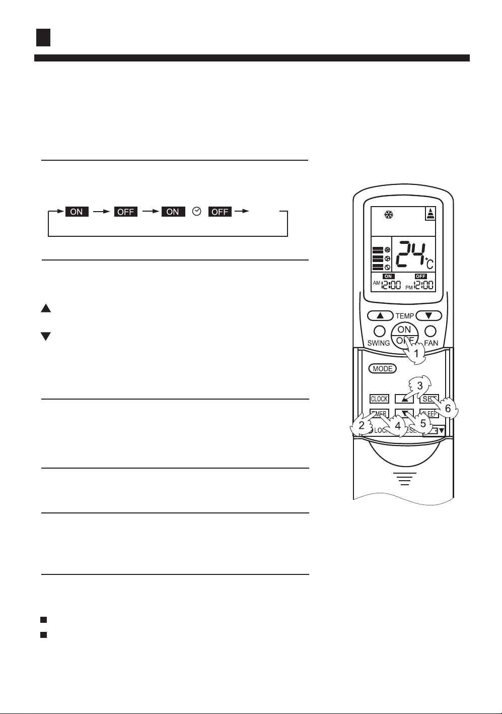
(1)After unit start, select your desired operation mode.
Operation mode will be displayed on LCD.
Power indicator on indoor unit lights up.
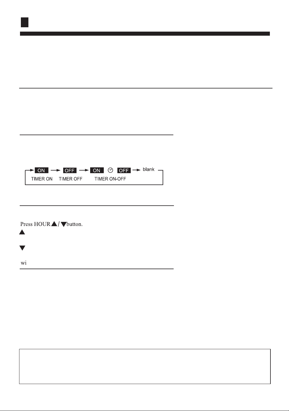
(2)TIMER mode selection
Press TIMER button to change TIMER mode.
Every time the button is pressed, display changes as follows:
Select your desired TIMER mode (TIMER ON or TIMER
OFF) ON or OFF will flash.
(3)Timer setting
(4)Confirming your setting
After setting correct time, press SET button to confirm "ON"
or "OFF" stops flashing
Time displayed: Unit starts or stops at x hour x min (TIMER
ON or TIMER OFF).
Timer mode indicator on indoor unit lights up.
To cancel TIMER mode
Just press TIMER button several times until TIMER mode disappears.
Hints
After replacing batteries or a power failure happens, Time setting should be reset.
Remote controller possesses memory function, when use TIMER mode next time, just
press SET button after mode selecting if timer setting is the same as previous one.
13
Page 16
GUIDE TO OPERATION
TIMER ON-OFF
(1)After unit start, select your desired operation mode
Operation mode will be displayed on LCD.
Power indicator on indoor unit lights up.
(2)Press TIMER button to change TIMER mode
Every time the button is pressed, display changes as follows:
blank
TIMER OFFTIMER ON TIMER ON-OFF
Select TIMER ON-OFF, "ON" will flash.
(3)Time setting for TIMER ON
Press HOUR button.
Every time the button is pressed, time increases 10min.
If button is kept depressed, time will change quickly.
Every time the button is pressed, time decreases 10min.
If button is kept depressed, time will change quickly. Time
will be shown on LCD.
It can be adjusted within 24hours.
AM refers to morning and PM to afternoon.
(4)Time confirming for TIMER ON
After time setting, press TIMER button to confirm.
"ON" stops blinking, While "OFF" starts blinking.
Time displayed: Unit starts at X hour X min.
(5)Time setting for TIMER OFF
Follow the same procedures in "Time setting for TIMER ON".
(6)Time confirming for TIMER OFF
After time setting, press SET button to confirm "OFF" stops flashing.
Time displayed: Unit starts at X hour X min.
To cancel TIMER mode
Just press TIMER button several times until TIMER mode disappears.
According to the Time setting sequence of TIMER ON or TIMER OFF, either Start-Stop or
Stop-Start can be achieved.
14
Page 17
GUIDE TO OPERATION
Adjusting up/down air flow direction
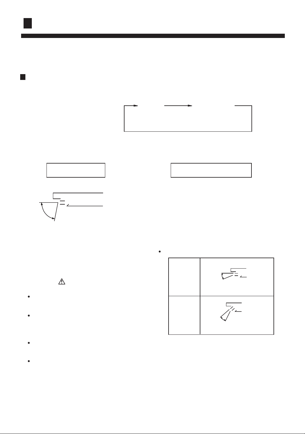
Up/down direction can be adjusted by using the SWING button on the remote controller.
Each time pressing this button, the mode changes in the following sequence.
Change to the AIRFLOW mode.
SWING
Louver moves in upward and
downward directions continuously.
CAUTION
Avoid direct air flow to the body
for many hours.
Avoid downward blowing operation of cooling mode for many
hours.
Do not touch the swing louver
during swing operation.
Please use the Swing button of
remote controller. If adjusted by
hand, it would cause an injure.
(Only for 24,28,36,42 series.)
SWING
No indication
(louver stopped)
LOUVER STOPPED
When the LOUVER button is
pushed during SWING mode,
it stops swinging at the just
angle.
Recommendable stopping angle of the louver
COOL
and
DRY
(Horizontal Blowing)
HEAT
(Downward Blowing)
15
Page 18
GUIDE TO OPERATION
LOCK
RESET
16
about 6 hrs
1 hr
1 hr
Page 19

GUIDE TO OPERATION
Remote Control:
There is a telecommunication interface for remote control on the control panel of the indoor unit.
After the peripheral equipment have been installed in accordance with the instruction manual of
the selected remote control detector, the air conditioner will be computerized and controlled from a
far-away place.
Power Failure Compensation (to be applied for a necessary situation)
After the power failure compensation is set, if power failure suddenly occurs while the air conditioner
is working, it will resume the previous working state when the power is supplied again.
Setting Method: When the remote controller is on (excluding timer mode and fan mode),
press the "Sleeping" button on the remote controller 10 times within 5
seconds, and after the buzzer rings 4 times, the air conditioner will enter
the state of power failure compensation.
Cancel Method: Press the "Sleeping" button on the remote controller 10 times within 5
seconds, and after the buzzer rings 2 timer, the power failure compensation
mode will be cancelled.
Notes: When a power failure suddenly occurs during the air conditioner is working after the power
failure compensation is set, if the air conditioner will not be used for a long time, please cut off the
power supply to prevent its operation from being resumed after the power is supplied again, or press
the "Switch On/Off" button after the power comes again.
:
17
Page 20
CLEANING AND CARE
CAUTION!
Before cleaning the air conditioner ,be sure to turn it off and disconnect
the Power Supply Cord.
Be sure the Intake Grill is installed securely.
When removing and replacing the air filters, be sure not to touch the heat
exchanger, as personal injury may result.
Cleaning the Air Filter
(For Series 14,18)
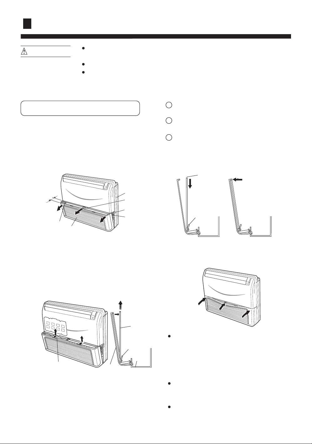
Open the Intake Grill
1. Pull out both sides and the center of the
Intake Grill.
About 30 mm
Arm
Intake Grill
Side Panel
Hook
Notch
Arm
4. Re-attach the Air Filters to the Intake Grill.
1
The Filters fit onto the inside of the intake
Grill. (figure 1)
2
The bottom edges of the Air Filters should
fit into the filter brackets. (figure 1)
3
The Air Filters should be pushed down so
that their top edges fit under the projections
at the top of the Intake Grill. (figure 2)
Air Filter
(Figure 1)
Filter bracket
(Figure 2)
2. Pull the Air Filters upward to remove
them.
Push the Air Filter handles away from the
Intake Grille in direction as illustrated, then
pull out Air Filters.
Air Filter
Bracket
Base
Handle
3. Clean the Air Filters.
Remove the dust from the Air Filters by
vacuum cleaner or washing them. After
washing, allow the Air Filters to dry
thoroughly in an area protected from sunlight.
5. Push in both sides and the center of the
Intake Grill.
Dust can be cleaned from the Air Filter
either with a vacuum cleaner, or by washing
the filter in a solution of mild detergent and
warm water. If you wash the filter, be sure
to allow it to dry thoroughly in a shady
place before reinstalling.
If dirt is allowed to accumulate on the Air
Filter, air flow will be reduced, lowering
operating efficiency and increasing noise.
During periods of normal use, the Air
Filters should be cleaned every two weeks.
18
Page 21
CLEANING AND CARE
CAUTION!
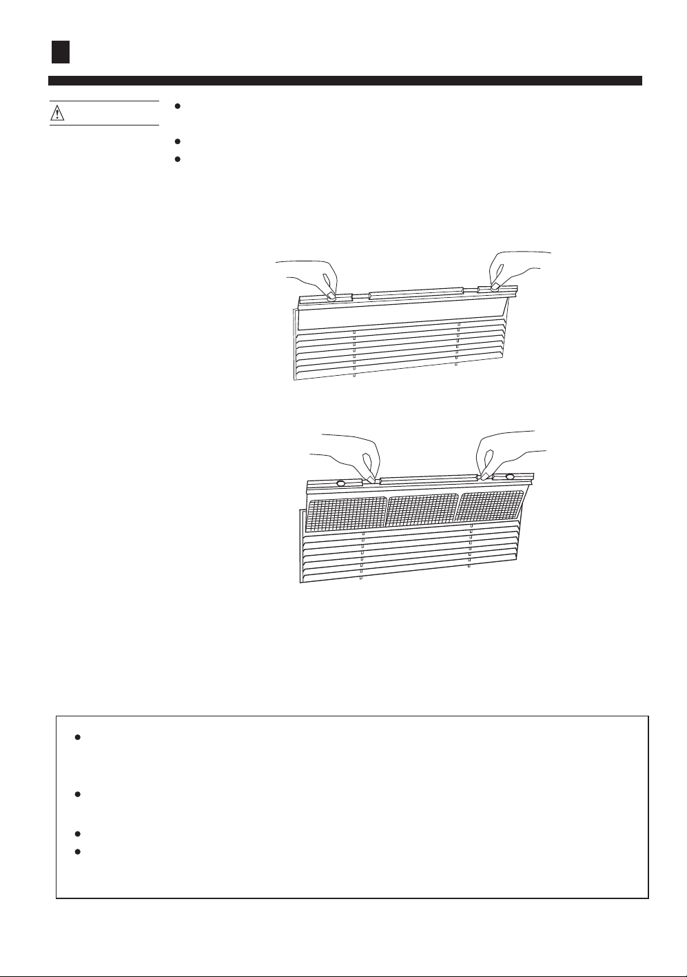
The following four procedures are for series 24,28,36,42.
1. Press the two buttons on the filters, until you hear a sound of click.
2. Pull the filters upward to remove them from the Intake Grill.
Before cleaning the air conditioner ,be sure to turn it off and disconnect
the Power Supply Cord.
Be sure the Intake Grill is installed securely.
When removing and replacing the air filters, be sure not to touch the heat
exchanger, as personal injury may result.
3. Clean the air filter: Remove the dust from the filters by vacuum cleaner or washing them. After
washing, allow the air filters to dry thoroughly in an area protected from sunlight.
4. Re-attach the air filters to the Intake Grill, press the two buttons on the filters, until you hear
a sound of click.
When used for extended periods, the unit may accumulate dirt inside, which reduces its
performance. We recommend that the unit is inspected regularly, in addition to your own
cleaning and care. For more information, consult authorized service personnel.
When cleaning the unit's body, do not use water hotter than 40çC, harsh abrasive
cleansers, or volatile agents like benzene or thinner.
Do not expose the unit body to liquid insecticides or hairsprays.
When shutting down the unit for one month or more, first allow the Fan mode to operate
continuously for about half a day to allow internal parts to dry thoroughly.
19
Page 22
TROUBLE SHOOTING
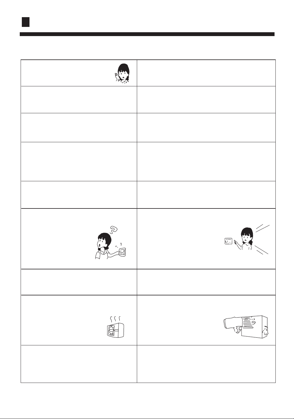
Followings are not problems
Sound of water flowing is
not a problem.
Sound of cracking is heard.
Smell are generated.
During operation, white fog or steam
comes out from the indoor unit.
In cooling operation, unit switches to
blowing operation.
Unit will not restart after stop.
Won't start?
During unit operation or at stop, a swishing or
gurgling noise may be heard. This noise is generated
by refrigerant flowing in the system.
During unit operation, a cracking noise may be heard.
This noise is generated by the casing expanding or
shrinking because of temperature changes.
This is because the system circulates smells from the
interior air such as the smell of cigarettes or the
painting on the furniture.
When unit is running at places like restaurant, etc. where
dense edible oil fumes always exist, this will happen.
To prevent frost from accumulating on indoor heat
exchanger, unit will switch to blowing operation for a
while then resume cooling operation.
Though ON/OFF button is set
to ON, unit won't resume cooling,
dry or heating operation
in 3 min after it is stopped, this
is because of 3-min-delay
protection circuit.
Please wait 3 minutes
No outlet air or fan speed can't be changed
in dry mode.
In heating operation, water or steam are
blown out of outdoor unit.
In heating operation, indoor fan won't stop
even if unit is stopped.
Unit will reduce fan speed repeatedly and automatically
if room temp. is too low in dry operation.
This occurs when frost accumulated
on the outdoor unit is removed.
(during defrosting operation)
After unit stop, indoor fan will go on running
until indoor unit cools down.
20
Page 23
TROUBLE SHOOTING
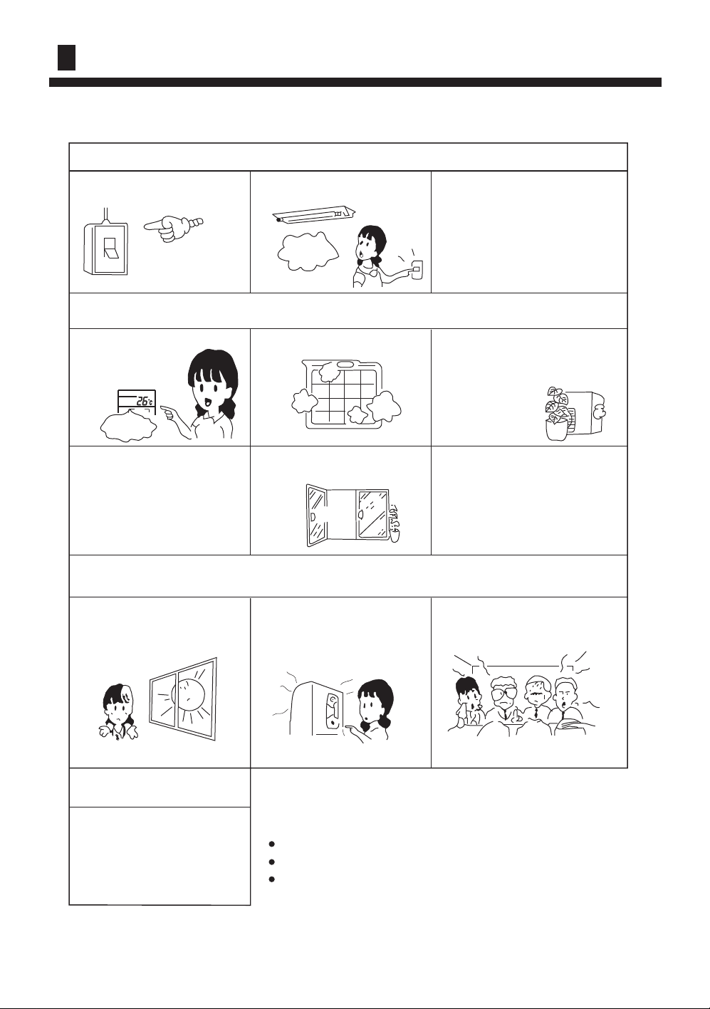
Before ask for services, please first check your unit against the following.
Air conditioner won't start.
Is power supply switch
turned on?
Power supply
switch is not
set at ON.
Are operation control
adjusted correctly
as specified?
Proper
temp
Are horizontal louvers at
up position (in heating
mode)?
Is city power supply normal? Is leakage current breaker
activated?
Power
failure?
This is very dangerous, please
disconnect power supply
immediately and contact your
dealer.
Poor cooling or heating
Is air filter too dirty?
Any doors or windows left
open?
Are there any obstacles in inlet
or outlet grill?
Poor cooling
Is there any direct sunlight
in the room?
Cold air blows out
(in heating mode)
Is air conditioner in standby
condition in heating mode?
If there are unexpected heat
sources in the room?
If your unit still can't work properly after above mentioned
checks, or following problems occur, please stop it immediately
and contact your dealer.
Fuses or circuit breakers often blow out.
Water comes out in cooling/dry operation.
Operation is abnormal or sound is heard.
21
Too many people in the room?
Page 24
 Loading...