

Page 1

R410A MULTI SPLIT SERIES ROOM AIR CONDITIONER
WALL MOUNTED TYPE INDOOR UNITS
OPERATION & INSTALLATION MANUAL
AS072XVERA
AS092XVERA
AS122XVERA
AS182XVERA
Please read this manual carefully before using this air conditioner.
Please keep this manual safely for future use.
No.0010576789 B
Page 2

Contents
Cautions
Safety precautions...............................................................................
Parts and Functions
Operation.........................................................................................
Notes for safety ...................................................................................
Operation and Maintenance
Trouble shooting
Customer Need-to-know
Instructions to installation
When trouble happens..........................................................................
Failure code .........................................................................................
.............................................................................................
...........................................................................
8-18
.................................................................
.............................................................................
.....................................................................
...............................................................
21-22
24-29
1-2
3-5
6-7
19
20
23
30
31
Page 3
Cautions
Disposal of the old air conditioner
Before disposing an old air conditioner
that goes out of use, please make sure it's
inoperative and safe. Unplug the air
conditioner in order to avoid the risk of
child entrapment.
It must be noticed that air conditioner
system contains refrigerants, which require
specialized waste disposal. The valuable
materials contained in a air conditioner can
be recycled. Contact your local waste
disposal center for proper disposal of an
old air conditioner and contact your local
authority or your dealer if you have any
question. Please ensure that the pipework
of your air conditioner does not get
damaged prior to being picked up by the
relevant waste disposal center, and
contribute to environmental awareness by
insisting on an appropriate, anti-pollution
method of disposal.
Disposal of the packaging of your new
air conditioner
All the packaging materials employed in
the package of your new air conditioner
may be disposed without any danger to the
environment.
The cardboard box may be broken or cut
into smaller pieces and given to a waste
paper disposal service. The wrapping bag
made of polyethylene and the polyethylene
foam pads contain no fluorochloric
hydrocarbon.
Consult your local authorities for the name and
address of the waste materials collecting
centers and waste paper disposal services
nearest to your house.
Safety Instructions and Warnings
Before starting the air conditioner, read the
information given in the User's Guide
carefully. The User's Guide contains very
important observations relating to the
assembly, operation and maintenance of the
air conditioner.
The manufacturer does not accept
responsibility for any damage that may arise
due to non-observation of the following
instructions.
Damaged air conditioners are not to be
put into operation. In case of doubt, consult
your supplier.
Use of the air conditioner is to be carried
out in strict compliance with the relative
instructions set forth in the User's Guide.
Installation shall be done by professional
people, and don't install the unit by yourself.
For the purpose of safety, the air
conditioner must be properly grounded in
accordance with specifications.
Always remember not to operate the air
conditioner before opening its inlet grill.
All these valuable materials may be taken to a
waste collecting center and used again after
adequate recycling.
1
Page 4
Cautions
All electrical repairs must be carried out
by qualified electricians. Inadequate repairs
may result in a major source of danger for
the user of the air conditioner.
Do not damage any parts of the air
conditioner that carry refrigerant by
piercing or perforating the air conditioner's
tubes with sharp or pointed items, crushing
or twisting any tubes, or scraping the
coatings off the surfaces. If the refrigerant
spurts out and gets into eyes, it may result
in serious eye injuries.
Do not obstruct or cover the ventilation
grille of the air conditioner. Do not put
fingers or any other things into the
inlet/outlet and swing louver.
Do not allow children to play with the air
conditioner. In no case should children be
allowed to sit on the outdoor unit.
4. The wiring method should be in line with
the local wiring standard.
5. The power cable and connecting cable are
self-provided.The requirement of the
connecting cable:
Model
AS072XVERA
AS092XVERA
AS122XVERA
AS182XVERA
Connecting cable
H05RN-F 3G 2.5mm2(For power)
H05RN-F 2X1.5mm2(For signal,
must use sheilded wires)
All the cables shall have got the local
authentication certificate.
6. The breaker of the air conditioner should
be all-pole switch; and the distance between
its two contacts should be no less than 3mm.
Such means for disconnection must be
incorporation in the fixed wiring.
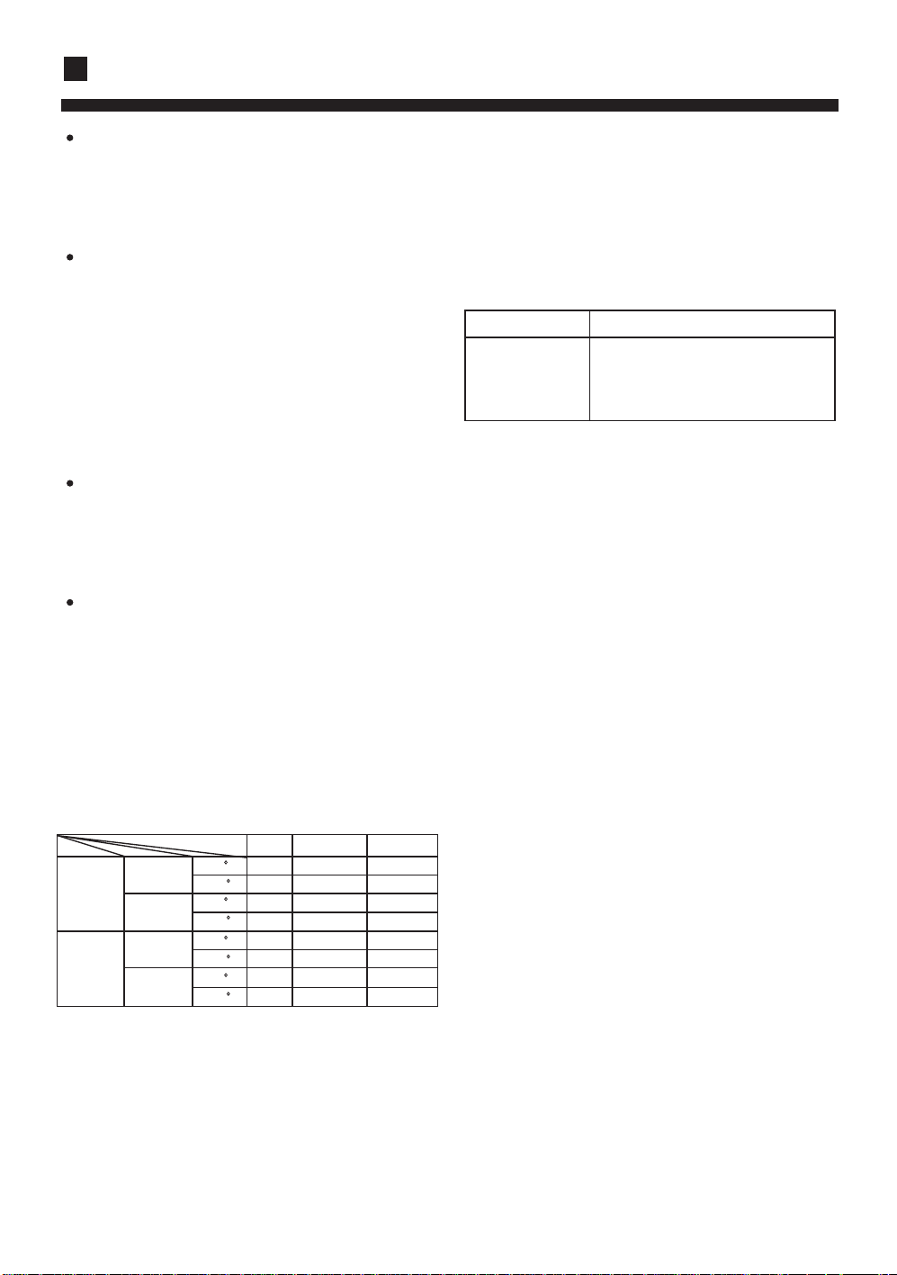
Specifications
The refrigerating circuit is leak-proof.
The machine is adaptive in following
situation
1. Applicable ambient temperature range:
Rated Maximum Minimum
27 32 18
Cooling
Heating
Indoor
outdoor
Indoor
outdoor
2. If the supply cord is damaged, it must be
replaced by the manufacturer or its service
agent or a similar qualified person.
3. If the fuse on PC board is broken, please
change it with the type of T 3.15A /250VAC
DB C
19 23 14
WB C
35 43 10
DB C
24 26 6
WB C
20 27 15
DB C
14.5 -- --
WB C
7 24 -7
DB C
6 18 --
WB C
7. The waste battery shall be disposed
properly.
8. The indoor unit installation height is at
least 2m.
9. The appliance is not intended for ase
young children or infirm persons without
super vision.
10. Young children should be supervised to
ensure that they do not play with the
applience.
2
Page 5
Safety precautions
Carefully read the following information in order to operate the air conditioner correctly.
Below are listed three kinds of Safety Cautions and Suggestions.
WARNING!
CAUTION!
INSTRUCTIONS: These information can ensure the correct operation of the machine.
Be sure to conform with the following important Safety Cautions.
The Safety Cautions should be at hand so that they can be checked at any time when needed.
If the conditioner is transferred to the new user, this manual should be as well transferred to the new user.
Incorrect operations may result in severe consequences of death or serious injuries.
Incorrect operations may result in injuries or machine damages; in some cases may
cause serious consequences.
WARNING!
Don't blow the human body with the cooling
air too long, and don't let the room temperature decrease too low either.
Otherwise the one will feel unpleasant
or harm ones' health.
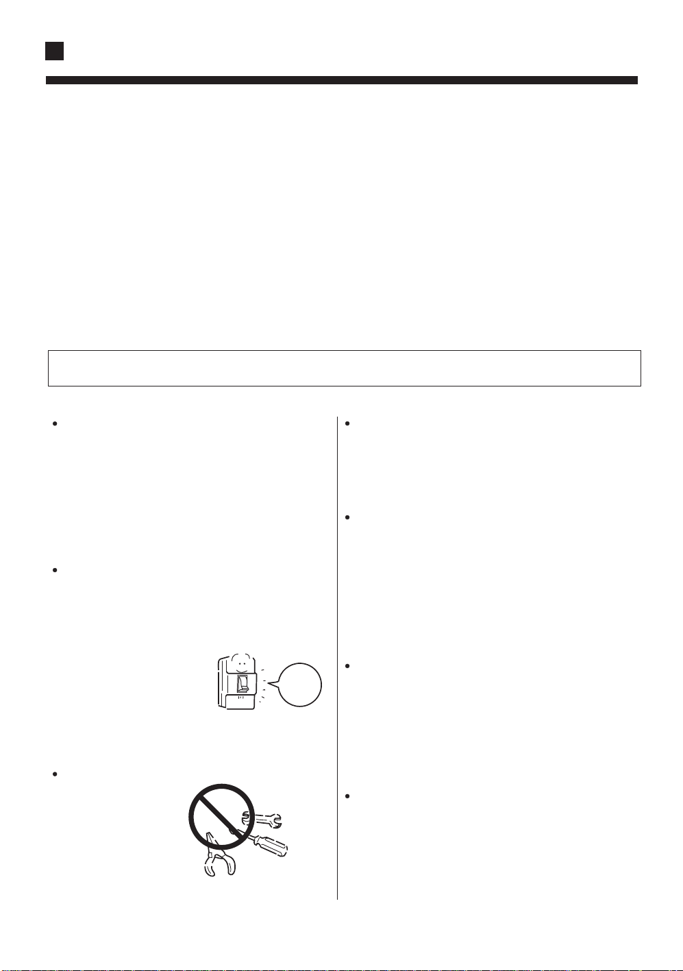
If any abnormal phenomena is found (e. g.
smell of firing), please cut off the power
supply immediately, and contact the dealer
to find out the handling method.
Please let the dealer be responsible for installing
the conditioner.
Incorrect installation may cause water leak, elec-
trical shock and fire hazard.
Don't put fingers or any other things into the
inlet/outlet and swing louver while the conditioner is in operation.
Because the highspeed fan is very dangerous
and may cause injuries.
In such case, to continue
using the conditioner will
damage the conditioner,
and may cause electrical
shock or fire hazard.
When need maintenance and repairment,
call dealer to handle it.
Incorrect maintenance and repairment
may cause water
leak, electrical shock
and fire hazard.
switch
off
Call the dealer to take measures to prevent the
refrigerant from leaking.
If conditioner is installed in a small room, be sure
to take every measure in order to prevent suffocation accident even in case of refrigerant leakage.
When conditioner is deinstalled or reinstalled
dealer should be responsible for them.
Incorrect installation may cause water leaking,
electrical shock and fire hazard.
3
Page 6
Safety precautions
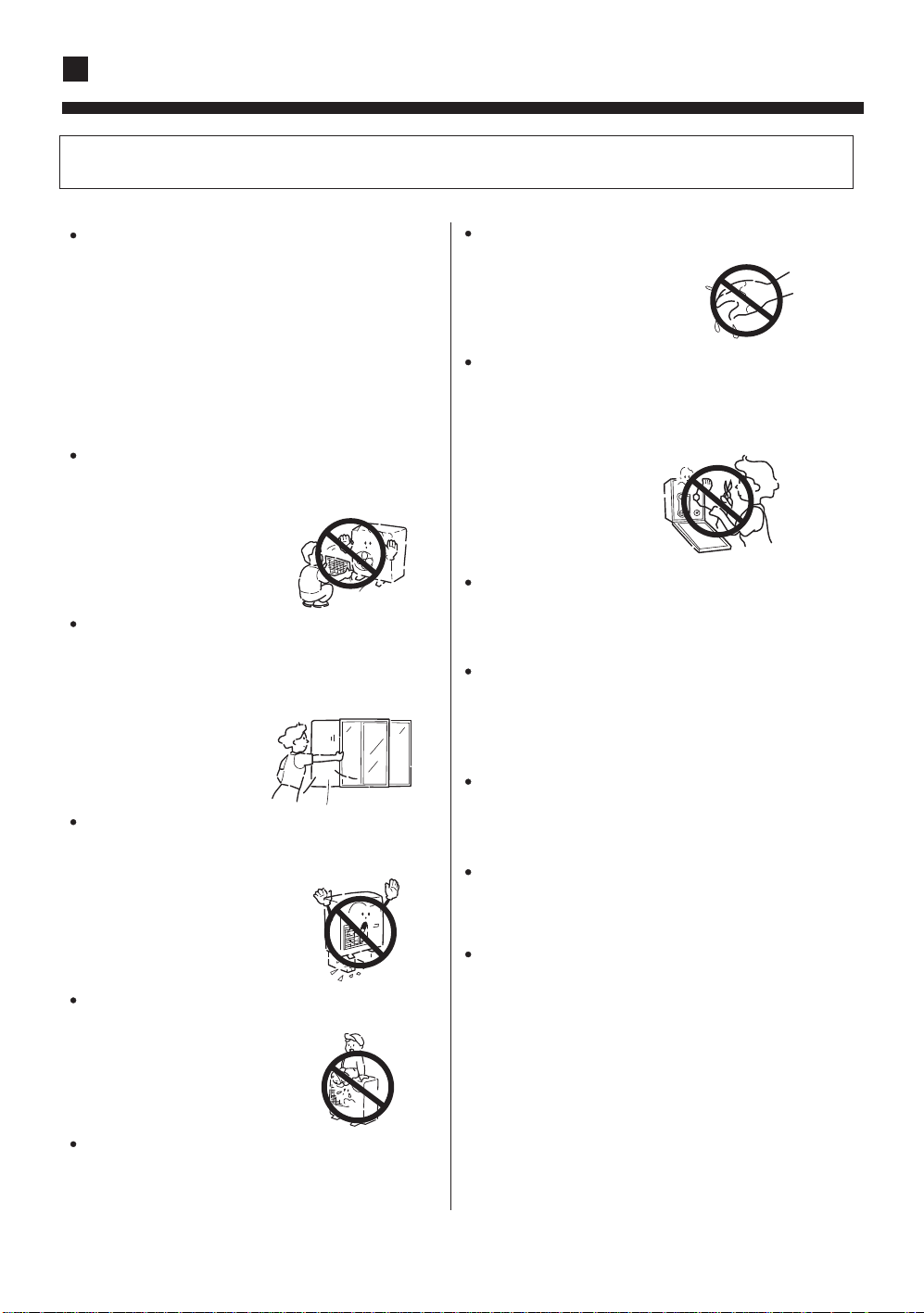
CAUTIONS!
Conditioner should not be used for any other
purpose other than airconditioning.
Don't use air-conditioner for any other special
purposes, e.g. the preservation and protection
of food, animals, plants, pecision apparatus as
well as work of art, otherwise the qualities
of these stuffs may be damaged.
Don't dismantle the outlet of the outdoor unit.
The exposure of fan is
very dangerous which
may harm human beings.
When air-conditioner is co-used with other
heat-radiator the frequent replacement of
room atmosphere should be required.
Inefficient ventilation may cause
suffocation.
After a long time use of air-conditioner the
base should be checked for any damages.
If the damaged base is
not repaired, the unit
may fall down and
cause accidents.
No goods or nobody is permitted to placed on
or stand on outdoor unit.
The falling of goods and
people may cause accidents.
Don't operate the air-conditioner with damp
hands.
Otherwise will be shocked.
Only use correctly-typed fuse.
May not use wire or any other materials
replacing fuse, otherwise may cause faults or
fire accidents.
Don't place any burning unit
air-conditioner,
combustion.
No inflammable spray fluid should be
permitted to be placed or used near to
airconditioner other wise may cause fire
accidents.
Air-conditioner should be cleaned only after
power supply is cut off to keep from shock or
hurt.
Don't clean air-conditioner with water.
Otherwise may cause shock.
When use the fumigating insecticide don't
open air-conditioner.
Otherwise the poisonous chemicals may settle
in air-conditioner which harm the health of
chemical-allergic people.
which may cause incomplete
in the air flow of
Pets and plants should not be blowed directly
in the air flow.
Otherwise will suffer damage.
4
Page 7
Safety precautions
CAUTIONS ON INSTALLATION
Please ask the dealer or specialist to install, never try by the users themselves. After the installation please
be sure of the following conditions.
Please call dealer to install the air-conditioner.
Incorrect installation may cause water leaking, shock and fire hazard.
CAUTION !
Air-conditioner can't be installed in the environment with inflammable gases because the
inflammable gases near to air-conditioner may
cause fire hazard.
Installed electrical-leaking circuit breaker.
It easily cause electrical shock without circuit
breaker.
[Location]
Air-conditioner should be located in well-vented
and easily-accessible place.
Air-conditioner should not be located in the
following places:
(a) Places with machine oils or other oil vapours.
(b) Seaside with high salt content in the air.
(c) Near to hot spring with high content of sulfide
gases.
(d) Area with frequent fluctuation of voltage e.g.
factory, etc.
(e) In vehicles or ships.
(f) Kitchen with heavy oil vapour or humidity.
(g) Near to the machine emitting electric-magnetic
waves.
(h) Places with acid, alkali vapuor.
TV, radio, acoustic appliances etc are at least 1 m
far away to the indoor unit, outdoor unit, power
supply wire, connecting wire, pipes, otherwise
images may be disturbed or noises be created.
Connect earthing wire.
Earthing wire should not be connected to the gas pipe, water pipe,
lightning rod or phone line, incorrect earthing may cause shock.
Use discharge pipe correctly to ensure efficient
discharge.
Incorrect pipe use may cause water leaking.
As required, take measures against heavy snow.
Earthing
[Wiring]
Air-conditioner should be equipped with special
power supply wire.
[Operating noise]
Chose the following locations:
(a) Capable of supporting air-conditioner weight,
don't increase operating noise and vibration.
(b) Hot vapour from outdoor unit outlet and ope rating noise don't disturb neighbour.
No obstacles around the outdoor unit outlet.
5
Page 8
Parts and Functions
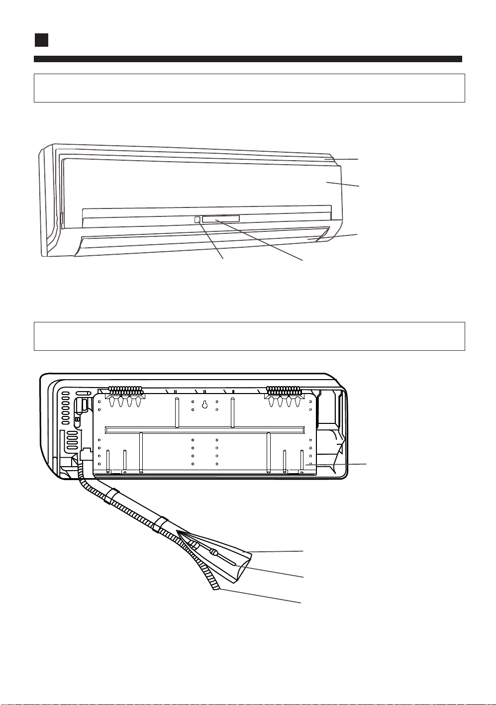
INDOOR UNIT FRONT VIEW
Air inlet grille
Front panel
Louver
Signal receiver
Display board
INDOOR UNIT BACK VIEW
Mounting plate
Heat preservation pipe
Connecting pipes
Drainage pipes
6
Page 9
Parts and Functions
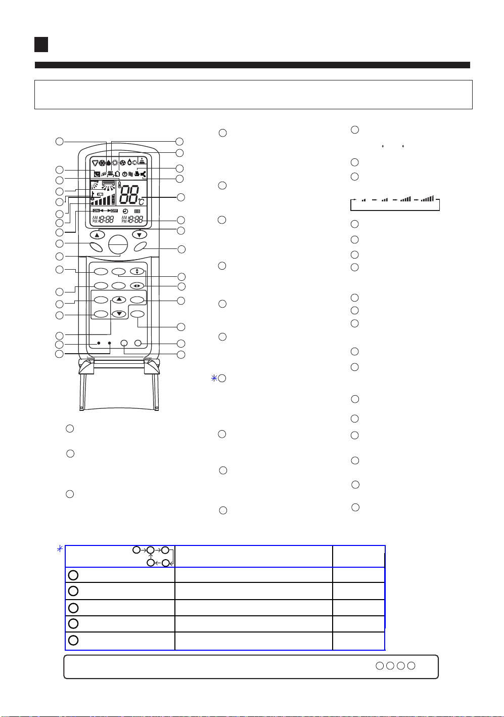
REMOTE CONTROLLER YR-H65
4
20
19
18
2
o
17
24
23
16
MODE
SLEEP
CLOCK
TIMER
TEMP
ON
OFF
HEALTH AIRFLOW
FRESH
15
11
HEALTH FAN
1
2
8
3
4
7
6
RESET
LIGHT
CODE
31
1
Power ON/OFF
Used for unit start and stop.
2
MODE
Used to select AUTO run,
COOL, DRY, HEAT and
FAN operation.
3
CLOCK
Used to set correct time.
The LIGHT function
power on the unit
1
2
press LIGHT button 1 times
press LIGHT button 2 times
3
4
press LIGHT button 3 times
press LIGHT button 4 times
5
SWING
SET
STERILIZE
LOCK
1
21
B
A
22
27
28
25
26
14
12
30
13
9
29
5
10
3
2
the control panel`s backgroud light source
5
4
TIMER
Used to select
TIMER ON, TIMER
OFF, TIMER
ON/OFF.
5
LOCK
Used to lock buttons
and LCD display.
6
RESET
Used to reset the
controller back to
normal condition.
HOUR
7
Used to set clock and
timer setting.
8
SLEEP
Used to select sleep
mode
9
SET
Used to confirm
Timer and Clock
setting.
10
LIGHT
Control the light up and go out
of the control panel's
background light source and
control the switch of the buzzer.
11
HEALTH
Used to set Health operation
function
12
FAN
Used to select fan speed: AUTO,
LOW FAN, MED FAN, HIGH
FAN.
13
SWING
Used to set UP/DOWN air
sending and RIGHT/LEFT air
sending direction.
on(about 5 seconds) normal
on(constantly)
on(about 5 seconds)
off
on(about 5 seconds) normal
14
TEMP
Used to set temp.,temp.
range:16 C~30 C
Timer ON/OFF display
15
16
Fan speed and air sending
direction display
LOW MID HIGH AUTO
17
Swing direction display
18
Room temperature display
Sleep state display
19
20
Health display
Display when set Health
operation function.
21
Electric Heating display
22
Fresh Air state display
23
Battery Capacity display
Display when the electric power
of the battery is insufficient.
24
Lock state display
Temperature display
25
Used to display the set
temperature
26
Clock display
27
Humidifying display
Sterilize display
28
(This function is optional)
29
STERILIZE
(This function is optional)
30
HEALTH AIRFLOW
Used to set health airflow
31
CODE A/B selection
For this unit, please set to code A
the buzzer
normal
null
normal
Note: This model does not have the following related display and function
7
21
18
27
23
Page 10
Operation
Clock set
When unit is started for the first time
and after replacing batteries in remote
controller, clock should be adjusted as follows:
Press CLOCK button, "AM"or "PM" flashes.
Press or to set correct time. Each press will increase
or decrease 1 min . If the button is kept pressed, time will
change quickly.
After time setting is confirmed, press SET, "AM" and "PM"
stop flashing, while clock starts working.
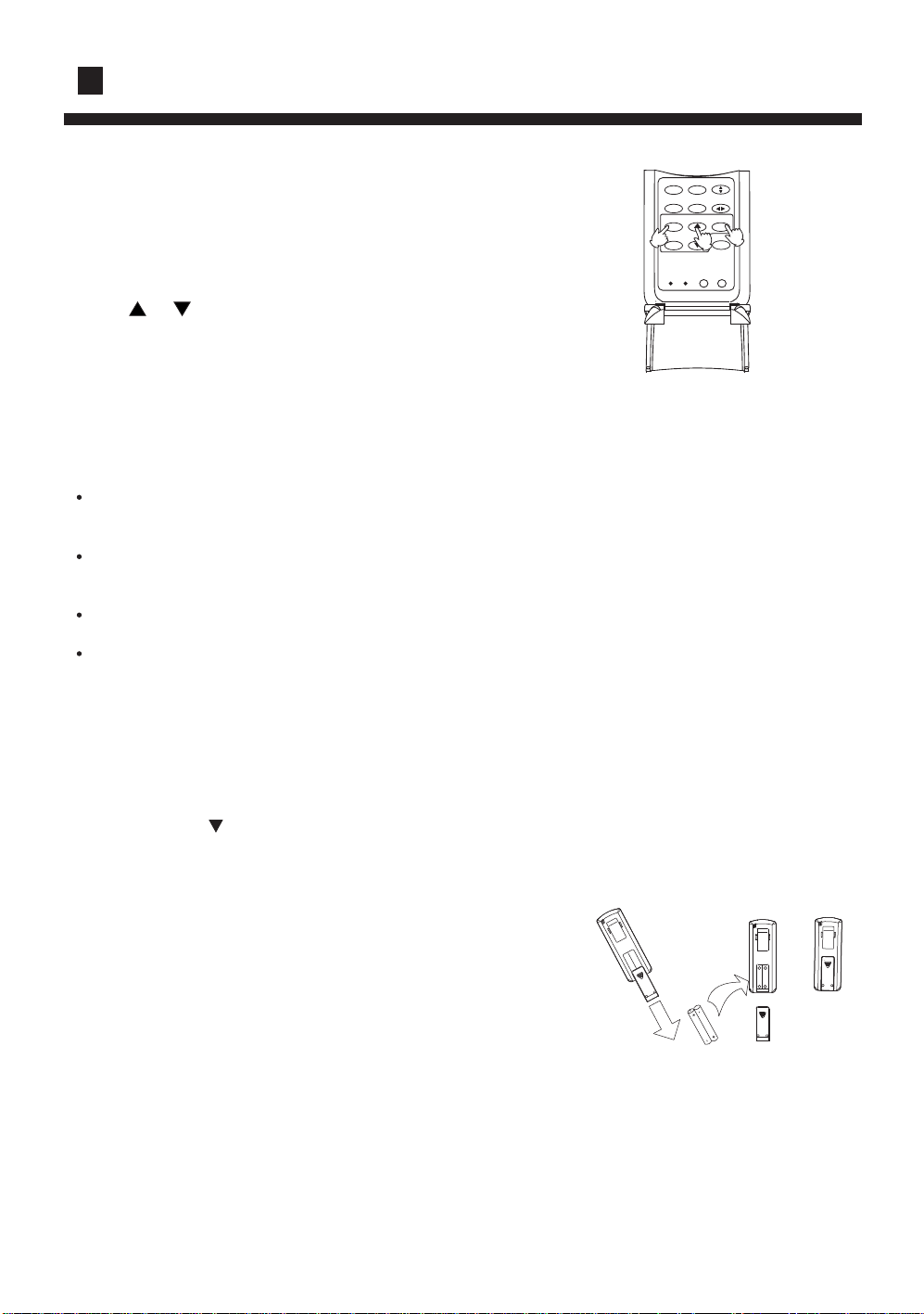
Remote controller's operation
When in use, put the signal transmission
head directly to the receiver hole on the
indoor unit
The distance between the signal transmission
head and the receiver hole should be within
7m without any obsacles as well.
Don't throw the controller, prevent it from
being damaged.
When electronic-started type fluorescent
lamp or change-over type fluorescent lamp
or wireless telephone is installed in the room,
the receiver is apt to be disturbed in receiving
the signal so the distance to the indoor unit
should be shorter.
MODE
HEALTH AIRFLOW
SLEEP
FRESH
SWING
SET
CLOCK
TIMER
STERILIZE
1
RESET
3
2
LOCK
LIGHT
CODE
Loading of the battery
Slightly press " " and push down the cover.
Load the batteries as illustrated.
2 R-03 dry batteries, (cylinder)
Be sure that the loading is in line with the "+"/"-" pole
request as illustrated.
Put on the cover again.
MINUTES
Confirmation indicator:
In disorderation, reload the batteries or load the new batteries
after 5 mins.
Note:The waster batteries should be disposed properly,use two
new same-type batteries when loading.
If the remote controller canít function normally or doesnít work at
all,use a sharp-pointed item to press the reset key.
Hint:Remove the batteries in case unit wonít be in usage for a long period.
If there are any displays after taking-out just need to press reset key.
When throw away the waste batteries, please perform in accordance with the local regulation.
8
2R-03 dry batteries
Page 11
Operation
A
TEMP
HEALTH
ON
OFF
5
MODE
HEALTH AIRFLOW
SLEEP
FRESH
2
CLOCK
TIMER
LIGHT
RESET
CODE
1
SWING
SET
STERILIZE
LOCK
3
FAN
4
Remote
controller
Auto
1
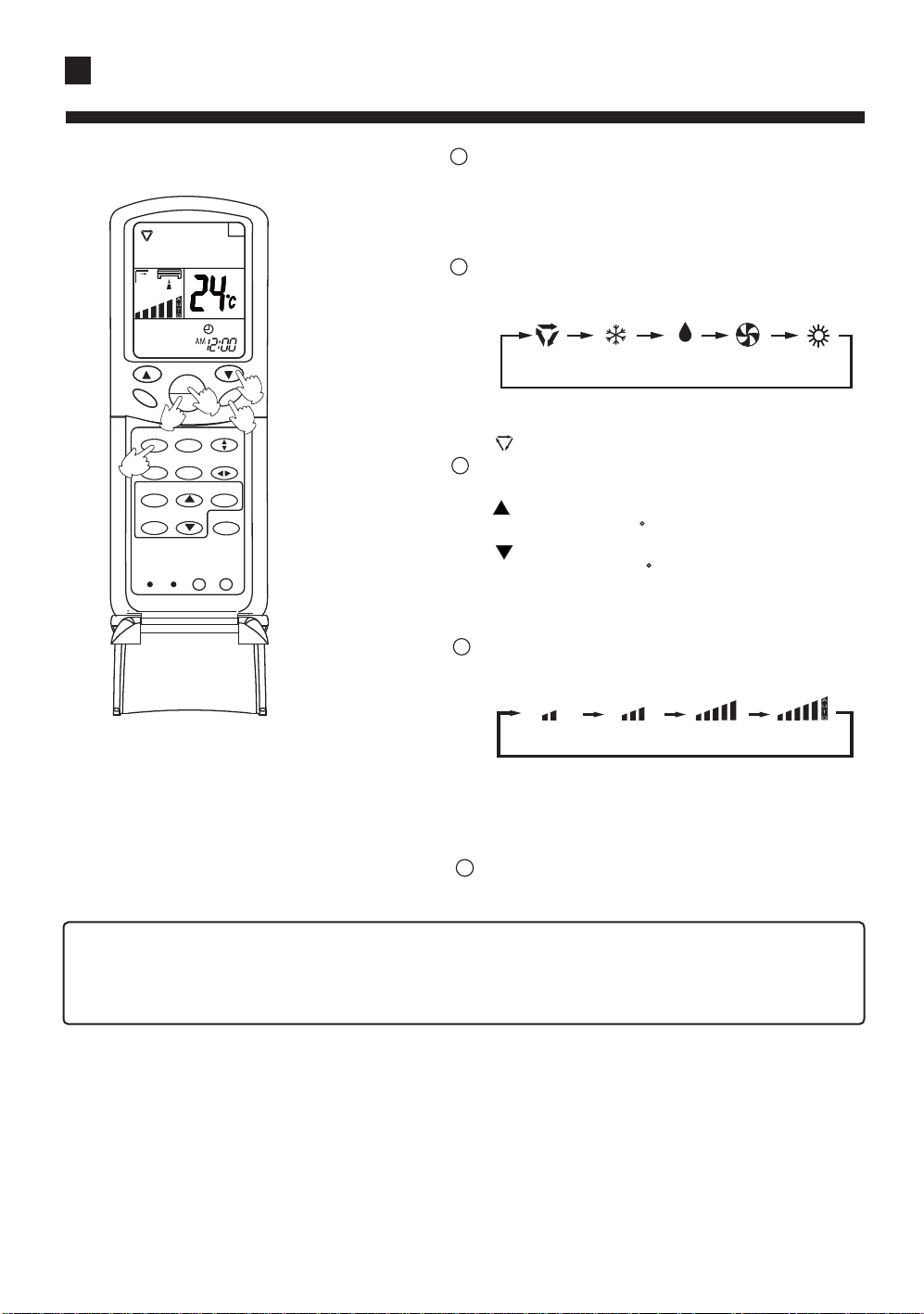
Press ON/OFF button
Unit starts running.
The previous status appears on the display
(except. TIMER, SLEEP mode)
2
Press MODE button. For each press,
operation mode changes as follows:
AUTO COOL DRY FAN HEAT
Select Auto run,
" " appears and auto run starts.
3
Select temp. button
Press TEMP button
Every time the button is pressed, temp.
setting increases 1 C
Every time the button is pressed, temp.
setting decreases 1 C
If the button is kept pressed, setting will
increase or decrease quickly.
4
Press FAN,For each press, operation mode
changes as follows:
Remote
controller
5
LOW MID HIGH AUTO
Unit runs at the speed displayed on LCD.
When fan speed is AUTO,it is changed automatically
according to the indoor temperature.
Press ON/OFF button
Unit stops running.
Note:
During Auto run operation, temp. setting will be shown in LCD display, unit will select heating,
cooling or fan operation according to the room temp.
9
Page 12

Operation
A
HEALTH
TEMP
3
ON
OFF
1
MODE
HEALTH AIRFLOW
SLEEP
FRESH
2
CLOCK
TIMER
LIGHT
RESET
CODE
5
3
FAN
4
SWING
SET
STERILIZE
LOCK
Remote
controller
1
Press ON/OFF button
Unit starts running.
The previous status appears on the display
(except. TIMER, SLEEP mode)
2
Press MODE button. For each press,
operation mode changes as follows:
AUTO COOL DRY FAN HEAT
Select cooling operation, Shows" "
Cooling operation starts.
3
Select temp. button
Press TEMP button
Every time the button is pressed, temp.
setting increases 1 C
Every time the button is pressed, temp.
setting decreases 1 C
If the button is kept pressed, setting will
increase or decrease quickly.
Cooling
4
Press FAN button. For each press, fan speed
changes as follows:
Remote
controller
LOW MID HIGH AUTO
Unit runs at the speed displayed on LCD.
When fan speed is AUTO,it is changed automatically
according to the indoor temperature.
5
Press ON/OFF button
Unit stops running,and when entry this mode for the
next time,it will show the previous setting.
10
Page 13

Operation
A
1
Press ON/OFF button
Unit starts running.
The previous status appears on the display
(except. TIMER, SLEEP mode)
2
Press MODE button. For each press, operation mode changes
as follows:
Dry
3
HEALTH
TEMP
ON
OFF
1
MODE
HEALTH AIRFLOW
SLEEP
FRESH
2
CLOCK
TIMER
5
3
FAN
4
SWING
SET
STERILIZE
Remote
controller
AUTO COOL DRY FAN HEAT
Select Drying operation shows" "
Dry operation starts
3
Select temp. button
Press TEMP button
Every time the button is pressed, temp. setting increases 1 C
LOCK
LIGHT
RESET
CODE
Every time the button is pressed, temp. setting decreases 1 C
If the button is kept pressed, setting will increase or decrease
quickly.
4
Press FAN button. For each press, fan speed changes as
follows:
Remote
controller
LOW MID HIGH AUTO
Unit runs at the speed displayed on LCD.
In DRY mode, when room temp.becomes 2 C lower than temp.
setting,unit will run intermittently at LOW speed regardless of FAN
setting.
5
Press ON/OFF button
Unit stops running, and when
entering this mode for the next
time, it will show the previous setting
11
COOL operation starts when room
temp. is higher than temp. setting.
Temp.setting+2 C
Temp.setting
On reaching 2 C lower than temp.
setting,unitwill run in mild DRY mode.
Ultra-low air flow
Page 14

Operation
A
TEMP
HEALTH
ON
OFF
1
HEALTH AIRFLOW
MODE
FRESH
SLEEP
2
CLOCK
TIMER
CODE
RESET
LIGHT
4
FAN
3
SWING
SET
STERILIZE
LOCK
1
Press ON/OFF button
Unit starts running.
The previous status appears on the display
(except. TIMER, SLEEP mode)
2
Press MODE button. For each press,operation mode
changes as follows:
Remote
controller
AUTO COOL DRY FAN HEAT
Select Fan operation shows " ", Fan operation starts.
3
Press FAN button. For each press, fan speed changes as
follows:
Fan
LOW MID HIGH
Unit runs at the speed displayed on LCD.
4
Press ON/OFF button
Unit stops running, and when entering this mode for the
next time, it will show the previous setting.
Note:
In this mode, temp. can't be selected, temp.setting will not be
shown in LCD display.In Fan operation mode, "AUTO" fan
speed is not available. Operation cycles are as follows:
LOW MID HIGH
12
Page 15

Operation
Note: For cooling only type, this function is invalid.
1
Press ON/OFF button
Unit starts running.
The previous status appears on the display
(except. TIMER, SLEEP mode)
2
Press MODE button. For each press,operation mode
changes as follows:
AUTO COOL DRY FAN HEAT
Select Heating operation " " appears and Heating
operation starts.
3
Select temp. button
Press TEMP button
Every time the button is pressed, temp. setting increases 1 C
Every time the button is pressed, temp. setting decreases 1 C
If the button is kept pressed, setting will increase or
decrease quickly.
3
HEALTH
A
TEMP
ON
OFF
1
HEALTH AIRFLOW
MODE
FRESH
SLEEP
2
CLOCK
TIMER
LIGHT
CODE
RESET
5
SWING
SET
STERILIZE
LOCK
3
FAN
4
Heating
4
Press FAN button. For each press, fan speed changes as
follows:
LOW MID HIGH AUTO
In heat mode,warm air will blow out after a short period of
time due to cold-draft prevention function.
5
Press ON/OFF button
Unit stops running, and when entering this mode for the next
time, it will show the previous setting.
13
Page 16

Operation
Swing louvers
(Vertical louvers)
(Horizontal louvers)
Up and down
Air flow adjustment
Side from side
HEALTH
RESET
MODE
SLEEP
CLOCK
TIMER
TEMP
ON
OFF
HEALTH AIRFLOW
FRESH
LIGHT
CODE
A
Position 1
Position 1
Position 2
Position 2
Position 3
FAN
Position 4
1
SWING
SET
2
STERILIZE
LOCK
Position 5
Position 6
[COOL/DRY/FA
N/AUTO(COOL)
HAVE NOT]
(AUTO SWING)
Position 3
Position 4
Position 5
Position 6
Position 7
Position 8
Fixed position
Press the SWING again to fix the
vertical louvers at your desired position.
Side from side
Swing
Press SWING the vertical
louvers move from side to side.
Note:
Put louvers at up position in cooling and down position in heating mode.
This will be helpful to keep an even room temp.
Notice:
In cooling or dry operation, don't put horizontal louvers at downward
position for a long time, or outlet grill might get frosted. Don't expose
your skin to cool or warm air for a long time.
Swing
Press SWING the horizontal
louvers move from up to down.
Fixed position
Press the SWING again to fix the
horizontal louvers at your desired position.
14
Page 17

Operation
Remote control unit
Before go to bed, you can press the Sleep button,
the air conditioner will operate in comfortable
sleep mode to make your sleep more comfortable.
Usage of the Sleep function
After starting, set the Run mode and press the Sleep
button.
Sleep
The Sleep running starts The Sleep running stops
About 6 hours
Run mode
1. In cooling and dry
After starting of the Sleep operation, the temperature will
be raised for 1 C higher than the set temperature 1 hour
later,and be raised for 1 C after another hour. It continues
under that condition for 6 hours, then the machine will be
switched off. The temperature is higher than the set
temperature so as to avoid catching cold in sleeping.
2. In heating ( the single-cooling conditioners do not have the
function)
After the Sleep running starts, the temperature will drop for 2 C after
one hour.The temperature will drop for 2 C after another one hour.
The temperature will raise for 1 C after 3 hours running under the
above temperature, and the conditioner will be closed down after
running for 3 hours. The temperature is lower than the set
temperature so as to avoid uneasiness in sleeping.
HEALTH
MODE
SLEEP
CLOCK
TIMER
TEMP
ON
OFF
HEALTH AIRFLOW
FRESH
A
FAN
SWING
SET
STERILIZE
Set the
temperature
Set the
temperature
1 hour
1 hour
1 hour
1 hour
Drop for 2 C
Drop for 2 C
3 hours
Raise 1 C
Raise 1 C
In cooling and dry
Close down
the machine
About 3 hours
Raise 1 C
Close down
the machine
RESET
CODE
LIGHT
LOCK
The Sleep running starts
In heating
The Sleep running stops
3. In automatic running
The conditioner will run under automatically selected working
mode of sleeping.
4. In Fan running
The Sleep function is invalid.
15
Page 18

Operation
Timer on/off operation
Remote control unit
TIMER operation
Set Clock correctly before starting Timer operation (refer to page 2)
You can let unit start or stop automatically at following times: Before you wake up in the morning, or get
back from outside or after you fall asleep at night.
TIMER ON/OFF
(1) After unit start, select your desired operation mode.
Operation mode will be displayed on LCD.
(2) TIMER mode selection
Press TIMER button to change TIMER mode.
Every time the button is pressed, display changes as follows:
Remote
controller
ON ONOFF OFF
AM
12:00
TIMER ON TIMER OFF TIMER ON-OFF
PM
12:00
AM
12:00
PM
12:00
BLANK
Select your desired TIMER mide (TIMER ON or TIMEROFF) ON or OFF
will flash.
TEMP
ON
MODE
SLEEP
CLOCK
TIMER
OFF
HEALTH AIRFLOW
FRESH
SWING
SET
STERILIZE
(3) Timer setting
Press HOUR / button.
Every time the button is pressed, time increases 10 min, If button is kept
pressed, time will change quickly.
Every time the button is pressed, time decreases 10 min, If button is
kept pressed, time will change quickly. Time will be shown on LCD. It can
HEALTH
be adjusted within 24 hours.
(4) Confirming your setting
After setting correct time, press SET button to confirm, " "
OFF
or " " stops flashing.
ON
RESET
CODE
LIGHT
LOCK
Time displayed: Unit starts or stops at x hour x min (TIMER
ON or TIMER OFF)
Timer mode indicator on indoor unit lights up.
To cancel TIMER mode
Just press TIMER button several times until TIMER mode disappears.
Hints
After replacing batteries or a power failure happens, Time setting should be reset.
Remote controller possesses memory function when use TIMER mode next time, just Press SET button
after mode selecting if timer setting is the same as previous one.
A
FAN
16
Page 19

Operation
Timer on-off function
Remote controller operation TIMER ON-OFF
(1) After unit start, select your desired operation mode.
Operation mode will be displayed on LCD.
(2) TIMER mode selection
Press TIMER button to change TIMER mode.
Every time the button is pressed, display changes as follows:
Remote
controller
ON ONOFF OFF
AM
12:00
PM
12:00
AM
12:00
PM
12:00
TIMER ON TIMER OFF TIMER ON-OFF
BLANK
Select your desired TIMER mide (TIMER ON or TIMEROFF) ON or OFF
will flash.
(3) Timer setting for TIMER ON
Press HOUR button.
Every time the button is pressed, time increases 10 min. If button is
kept pressed, time will change quickly.
Every time the button is pressed, time decreases 10 min. If button
is kept pressed, time will change quickly.
Time will be shown on LCD.
It can be adjusted within 24 hours.
AM refers to morning and PM to afternoon.
(4) Time confirming for TIMER ON
After time setting, press TIMER button to confirm," " stops blinking,
while " " starts blinking.
OFF
ON
(5) Time setting for TIMER OFF
Follow the same procedure in "Time setting for TIMER ON".
(6) Time confirming for TIMER OFF
After time setting, press SET button to confirm, " " stops flashing.
OFF
Time displayed: Unit start or stop at x hour x min
HEALTH
2
RESET
MODE
SLEEP
CLOCK
TIMER
TEMP
ON
OFF
1
HEALTH AIRFLOW
FRESH
3
4
LIGHT
CODE
5
SWING
SET
STERILIZE
LOCK
A
FAN
6
To cancel TIMER mode
Just press TIMER button several times until TIMER mode disappears.
According to the Time setting sequence of TIMER ON or TIMER OFF,either ON-OFF or OFFON can be achieved.
17
Page 20

Operation
Health & Fresh Air operation
HEALTH
RESET
MODE
SLEEP
CLOCK
TIMER
1
HEALTH AIRFLOW
CODE
TEMP
ON
OFF
FRESH
LIGHT
SWING
SET
STERILIZE
LOCK
A
Health operation
After turning on the unit and set the desired working mode. Press
the Health button, the LCD will display " ", the unit begins
health operation (start the negative ion generation device). Press the
Health button again, the " " displayed on the LCD disappears,
health operation is cancelled (turn off the negative ion generation
device).
Note: When indoor fan motor does not work, the unit will
FAN
automatically turn off negative ion generation device.
About Health operation
After the start of Health operation, the negative ion generator will
generate large amount of negative ion, which can effectively
balance the amount of positive & negative ion in the air and has the
bacteria-killing and accelerating the dust deposition of the room to
make the room air fresh and healthy.
18
Page 21

Notes for safety
Clean the dust filter periodically:
Blockage of the dust filter would reduce the
cooling and heating effect, consume more
power, water would be leaked during cooling,
and other failures would also occur.
Use the fuse of required capacity:
Never use steel wire or copper wire to take
place of the fuse.
!
Never connect the earth wire with the gas pipe,
water pipe, lightening arrester, or phone line.
Do not spray any paint or insecticide on the air conditioner.
Insecticide
Never install the air conditioner where the
flammable gas is easily leaked.
!
Paint
Never pour water on the indoor unit. Keep the inlet and outlet of the didoor unit
unblocked.
When the louver is being swung, never touch the
outlet or put anything into the air grille.
Operate the unit with the remote controller.
!
!
The instructions with this warning mark must be carried out strictly,for they are all
concerned with safety of the product or human beings.
The instructions with this prohibiting mark must be completely forbidden,otherwise
the product would be damaged or the human being would be injured.
19
Page 22

Operation and Maintenance
Emergency and Test Operation
Emergency operation:
Use this operation only when the remote controller is defective or lost.
When the emergency operation switch is pressed "Pi" sound is heard once,
which means the start of this operation.
In this operation,the system automatically selects the operation modes, cooling
or heating, according to the room temperature.
When machine is running in emergency, the set value and wind speed of
temperature could not be altered; meanwhile, it can not operate for
dehumidifying or under timing mode.
Test operation
pi
Test operation switch is the same as emergency switch.
Use this switch in the test operation when the room temperature is below
16 oC, do not use it in the normal operaion.
Continue to press the test operation swich for more than 5 seconds, after
you hear the "Pi" sound twice, release your finger from the switch:the
cooling operation starts with the air flow speed "Hi".
pi.....pi
Removal of the restriction of emergency or test operation.
Press the emergency operation switch once more, or manipulate through the remote controller ;
the "Pi" sound, the emergency or test operation is stopped.
When the remote controller is manipulated, it gets the system back to the normal operation mode.
Disconnect power supply before clean the unit.
Don' t touch it with wet hand.
Don' t wash with hot water or solvent to clean the unit.
Air filter and outdoor cleaning
1.Open the inlet grill.
2.Detach the Air filters.
3.Use water or vacuum cleaner to clean it. If it is extremely dirty,wash it with neutral detergent or soap water.
4.Wash it with clean water and install it after complete dry.
5.Close the inlet grill.
Caution:
Do not use hot water over 40oC, as this may cause damage to air filter.
Wipe air filter carefully.
Clean it with warm and wet cloth or with neutral detergent, then wipe it dry with clean and soft cloth.
If air conditioner is very dirty, clean it with cloth soaked in neutral detergent, then wipe off the detergent
with clean water.
Don't use insecticide or other chemical detergents.
20
Page 23

Trouble shooting
The followings are not malfuncition
Water flowing sound is heard
Hua
Hua
Cracking sound is heard
It smells.
During operation, white fog comes out of
indoor unit.
When the air conditoner is started, when the
compressor starts or stops during operation
or when the air conditioner is stopped,it sometimes sounds ì Bi- Bi-î or ìGodo-Godoî. It is
the flowing sound of the refrigerant , not a
malfunction.
This is caused by heat expansion or contraction of plastics
Air blown out from the indoor unit sometimes
smells. The smell results from smells of
furniture, paint , tobacco absorbed by indoor
unit.
When in COOL or DRY mode, a thin water
fog can be seen blown out of unit ,this is the
condensed fog because the suddenly cooled
indoor air is blown out.
Automatically switch into FAN mode during
cooling.
The air conditioner cannot be restarted soon
after it stops.
Air conditioner does not start?
To prevent frost from being accumulated on the
indoor unit heat exchanger, it sometimes automatically switched into the FAN mode,but it will
soon back to the cooling mode.
This is because of the self-protection function
of the system, therefore,it cannot be restarted
for about three minutes after it stops.
Please wait for three minutes
21
Page 24

Trouble shooting
Air does not blow or the fan speed cannot be
changed during drying.
Water or vapor generated from the outdoor
unit during heating.
During heating,indoor fan is still running even
unit is stopped.
In DRY mode, when room temperature
becomes 2 C higher than temperature setting,
unit rill run intermittently at LO speed regardless
of FAN setting
This happens when the frost accumulated on
the outdoor unit is removed (during defrosting
operation).
Defrosting operation
To get ride of the excess heat, indoor fan will
continue running for a while after unit automatically stops.
Please check the following things about your air conditioner before making a service call.
Is the power supply switch on ?
**?
Power supply switch is not in
ON position.
Unit fails to start.
Is city supply power normal ?
ON
OFF
22
Is the earth leakage breaker
in action ?
Be sure to turn off the power
supply switch immediately and
contact the sales dealer.
Page 25

Customer Need-to-know
Customer Need-to-know
Please install the air conditioner according to the requirements specified in this manual to ensure
the air conditioner work well.
Be careful not to scratch the surface of the case during moving the air conditioner.
Please keep the installation manual for future reference when maintenance and changing installation place.
After installation ,please use the air conditioner according to the specification in the operation
manual.
Using Directions
Adjust suitable airflow direction
Keep the proper indoor temperature.
Too cool or hot is not good for your health.
Furthermore,it will result in excessive
consumption of electric power.
Best temperature
Avoid direct sunlight and airflow
Effectively use timer.
Using TIMER mode, you can make the room
temperature reach a suitable temperature when
you wake up or go back home.
ATTENTION: After finishing installation, please confirm there is no refrigerant leakage.
23
Page 26

Instructions to installation
1. Safety precautions
Please read these "Safety Precautions" first then accurately execute the installation work.
Though the precautionary points indicated herein are divided under two headings,
and , those points which are related to the strong possibility of an installation
done in error resulting in death or serious injury are listed in the section.
WARNING
CAUTION
However, there is also a possibility of serious consequences in relationship to the points listed
in the section as well.
CAUTION
In either case, important safety related information is indicated, so by all means, properly
observe all that is mentioned.
WARNING
This system should be applied to places as office, restaurant, residence and the like. Application to inferior
environment such as engineering shop could cause equipment malfunction.
Please entrust installation to either the company which sold you the equipment or to a professional contractor.
Defects from improper installations can be the cause of water leakage, electric shocks and fires.
Execute the installation accurately, based on following the installation manual. Again, improper installations
can result in water leakage, electric shocks and fires.
When a large air-conditioning system is installed to a small room, it is necessary to have a prior planned
countermeasure for the rare case of a refrigerant leakage, to prevent the exceeding of threshold concentration.
In regards to preparing this countermeasure, consult with the company from which you perchased the equipment,
and make the installation accordingly. In the rare event that a refrigerant leakage and exceeding of threshold
concentration does occur, there is the danger of a resultant oxygen deficiency accident.
For installation, confirm that the installation site can sufficiently support heavy weight. When strength is
insufficient, injury can result from a falling of the unit.
Execute the prescribed installation construction to prepare for earthquakes and the strong winds of typhoons
and hurricanes, etc. Improper installations can result in accidents due to a violent falling over of the unit.
For electrical work, please see that a licensed electrician executes the work while following the safety standards
related to electrical equipment, and local regulations as well as the installation instructions, and that only
exclusive use circuits are used.
Insufficient power source circuit capacity and defective installation execution can be the cause of electric
shocks and fires.
Accurately connect wiring using the proper cable, and insure that the external force of the cable is not conducted
to the terminal connection part, through properly securing it. Improper connection or securing can result in
heat generation or fire.
Take care that wiring does not rise upward, and accurately install the lid/service panel. Its improper installation
can also result in heat generation or fire.
When setting up or moving the location of the air conditioner, do not mix air etc. or anything other than the
designated refrigerant within the refrigeration cycle.
Rupture and injury caused by abnormal high pressure can result from such mixing.
Always use accessory parts and authorized parts for installation construction. Using parts not authorized by
this company can result in water leakage, electric shock, fire and refrigerant leakage.
WARNING
CAUTION
Execute proper grounding. Do not connect the ground wire to a gas pipe, water pipe, lightning rod or a
telephone ground wire. Improper placement of ground wires can result in electric shock.
The installation of an earth leakage breaker is necessary depending on the established location of the unit.
Not installing an earth leakage breaker may result in electric shock.
Do not install the unit where there is a concern about leakage of combustible gas.
The rare event of leaked gas collecting around the unit could result in an outbreak of fire.
For the drain pipe, follow the installation manual to insure that it allows proper drainage and thermally insulate
it to prevent condensation. Inadequate plumbing can result in water leakage and water damage to interior
items.
24
Page 27

Instructions to installation
PRECAUTION
Execute proper grounding. Do not connect the earth wire to a gas pipe, water pipe, lightening rod,
or a telephone ground wire. Improper placement of earth wires can result in electric shock.
An electric leakage breaker must be installed, otherwise electric shock or other accidents would occur.
After completion of the installation, the air conditioner shall be electrified to check for electric leakage.
2. Preparation for installation
Installation tools
1 Screw Driver (flat head, wabbler, triangle)
2 Steel Saw
3 60mm Drill
4 Inner Hexagon Spanner
5 Shifting Spanner
6 Spanner
7 Pipe Cutter
8 Pipe Expander
9 Knives
10 Clippers
11 Leakage Checker or Soap Liquid
12 Measuring Tape
13 Scraper or File
14 Refrigeration Oil
3. Accessories for installation
Self-contained accessories
No. A B
Name of
Parts
Non-adhesive
Tape
Adhesive
tape
C D E F
Connecting
Hose
Heat
insulation
material
4. Choose the installation place
Install the indoor unit where the weight of the unit can be supported.
Gypsum
powder
Drain hose
Install the indoor unit where the heat source and steam source are not close and the unit inlet and
outlet are not blocked.
Install the indoor unit where the drainage is easy and the outdoor unit can be easily connected.
Install the indoor unit where its cold air and hot air can be easily sent to all the comers of the room.
Install the indoor unit where the power socket is near and there is sufficient space around the indoor unit.
Install the indoor unit where there is no T.V set, radio set, and wireless applian ce underneath, and the
sunlight lamp is over one meter away.
If the remote controller is installed on the wall, the indoor unit shall be ensured to receive the signal
while the sunlight lamp is on.
25
Page 28

Instructions to installation
5. Method for Cutting and Expanding Pipes.
When the pipe is too long or the mouth is damaged, the pipe needs to cut or expanded.
1.cutting hose 2.Removing burr 3.Put on nut 4.Expand Hose
A
Hose Expander
Correct Not Correct
cracks on expanded mouth burr incomplete too longTilting
6. When the mounting plate is first fixed
1. Carry out, based on the neighboring pillars or lintels, a proper leveling for the plate to be
fixed against the wall, then temporarily fasten the plate with one steel nail.
2. Make sure once more the proper level of the plate, by hanging a thread with a weight from the
central top of the plate, then fasten securely the plate with the attachment steel nail.
A=80mm
60mm
35
2-5mm
3. Making a Hole on the wall and Fitting the piping Hole cover.
Make a hole of 60mm in diameter, slightly descending to outside the wall.
Install piping hole cover and seal it off with putty after installation.
4. Drawing of pipe Rear piping
Draw pipes and the drain hose, then fasten them with the adhesive tape. Left Left-rear, piping.
In case of left side piping, cut away, with a nipper, the lid for left piping.
In case of left-rear piping, bend the pipes according to the piping direction to the mark of hole for
left-rear piping which is marked on heat insulation materials.
(1) Insert the drain hose into the dent of heat insulation materials of indoor unit.
(2) Insert the indoor/outdoor electric cord from backside of indoorunit, and pull it out on the front side,
then connect them.
(3) Coat the flaring seal face with refrigerant oil and connect pipes.
Cover the connection part with heat insulation materials closely, and make sure fixing with adhesive tape.
Indoor side
Wall hole
70mm
(Section of wall hole) Piping hole pipe
Outdoor side
Thickness
of wall
26
Page 29

Instructions to installation
Heat insulation
material
signal wire
Piping
Lid for right piping
Lid for under piping
Lid for left piping
Fix with adhesive tape
Drain hose
Indoor/outdoor
electric cable
Indoor/outdoor electric cord and drain hose must
be bound with refrigerant piping by protecting tape
Change-for-fresh-air tube
7. Other direction piping
Cut away, with a nipper, the lid for piping according to the piping direction and then bend the
pipe according to the position of wall hole. When bending, be careful not to crash pipes.
Connect beforehand the indoor/outdoor electric cable, and then pull out the connected to the heat
insulation of connecting part specially.
Hang surely the unit body onto the upper notches of the mounting plate. Move the body from
side to verify its secure fixing.
In order to fix the body onto the mounting plate, hold up the body aslant from the underside
and then put it down perpendicularly.
The distance between the signal wires and the power cabes should be at least 50mm.
Indoor unit D
C1 C2 C1 C2
Indoor unit C Indoor unit B Indoor unit A
L N
C1,C2
To the outdoor unit
Communication cable (Shield wire): H05RN-F 2X1.5mm
Connecting cable : H05RN-F 3G 2.5mm
2
2
Please refer to the indoor unit installation manual to find detailly how to set and check the communication
address.
27
Page 30

Instructions to installation
Incorrect address setting will cause abnormal to the system.and then put it down perpendicularly.
Signal connecting cable must be sheilded type.
8. Indoor unit communication addresses setting
CAUTION! FAIL TO DO THIS, THE UNIT WILL NOT WORK.
1.There are two methods to set the communication address
A. Use the remote controller(default status in first installation).
B. Use dip switches on the indoor unit PCB.
2. Address setting procedure when using the remote controller.
A. Set the addresses only after the successful installation of the refrigerant pipes and connecting cables, and
open all the stop valves;
B. Please confirm that the indoor units and the outdoor unit in the same system use the same power source;
C. Power on the units, but put all the indoor units in the status of STANDBY;
D. Please note that the address must be set as following:
Indoor unit that connect to valve A, the address must be 1;
Indoor unit that connect to valve B, the address must be 2;
Indoor unit that connect to valve C, the address must be 3;
Indoor unit that connect to valve D, the address must be 4;
E. Example: set unit A to address 1.
Continuously press the emergency switch for about 15 seconds, the buzzer will sound 4 times(PI PI PI PI)
and then leave go of the switch. At this time, the indoor unit has entered the address setting procedure. But
the LCD display board is blank.
F. Use the controller to turn on the indoor unit. At this time, the controller should be changed from OFF to
ON, and then the LCD display board will display number ì1î. That is to say, the address setting is enabled.
G. Press the button ìSLEEPî on the controller, the times you press it stands for the address you want to set,
detailed as following:
Press button ìSLEEPî one time, the address is ì1î, and the LCD display board shows ì1î;
Press button ìSLEEPî two times, the address is ì2î, and the LCD display board shows ì2î;
Press button ìSLEEPî three times, the address is ì3î, and the LCD display board shows ì3î;
Press button ìSLEEPî four times, the address is ì4î, and the LCD display board shows ì4î;
H. Use the remote controller to turn off the unit, At this time, the controller should be changed from ON to
OFF, and the unit will exit the address setting procedure, the address will be memorized. The LCD display
board will always display the address of this indoor unit until the system be powered off.
I. If you want to change the address, please repeat the above steps from E to G.
J. After setting all the addresses, please power of f the system and then power on again. Otherwise the system
will not start to work.
K. Once the addresses are successfully set, please do not change it any more to avoid confusion.
3. Address setting procedure when using the DIP switches SW01 and SW02.
A. The DIP switches SW01 and SW02 are on the indoor unit PCB.
B. Before carrying out the address setting work, the system must be powered off.
C. Take off the front panal and the filters, then take off the flaps and also the front cover,disconnect the swing
motor connectors from the PCB and then take out the lower part of the PCB.
D. Change the position of DIP 1 of SW01 from OFF to ON, if fail to do this, the addresses set by SW02
will not work.
E. Use SW02 to set the addresses as following(DO NOT CHANGE OTHER DIP SWITCHES):
28
Page 31

Instructions to installation
SW01
1 2 3 4 5 6 7 8
ON
OFF
SW02
1 2 3 4 5 6 7 8
1 2 3 4 5 6 7 8
1 2 3 4 5 6 7 8
1 2 3 4 5 6 7 8
INDOOR UNIT ADDRESS
ON
OFF
ON
OFF
ON
OFF
ON
OFF
1
2
3
4
4. How to check the addresses?
When finish all the above works, please power off and power on again to the whole system but set all
the indoor units in STANDBY. Then continously press the emergency switch until you hear the buzzer
sound 5 times(Pi Pi Pi Pi Pi), and then the LCD display board will show the address of this indoor unit.
Press any key on the remote controller, it will exit the address checking precedure.
9.Installation check and trial operation
Check the Layout of the Drain Pipe and Connection Wires, and also the piping and address setting.
The drain pipe should be placed underneath, and the connection wires should be placed upside;
and the drain pipe especially the section inside the machine and indoors must be wound up with
insulating material to preserve heat. The drain pipe shall be sloped and no concave and convex
shall occur along the whole pipe. And the cases as the right figure indicates shall not occur.
10.Installation check
Is power supply voltage required?
Is water completely drained to outdoors?
Are power wire and connection wires between indoor and outdoor units correctly connected?
Is any gas leaked from the pipe connectors?
Are series numbers of the terminals on the indoor and outdoor units corresponding to each other?
Is the connection section of the auxiliary pipe insulated? Is the indoor unit fixed firmly?
Is noise big?
11.Trial operation
The person who has completed this installation shall be requested to conduct a test operation for check:
Is the temperature adjuster working normally?
Does the location for installation conform to requirements?
Winding up with Protective Plastic Tape.The connection pipes,drain pipe, and the connection wires shall
be wound up with PVC tape.
Notes: The connection pipes shall also be wound up with insulating material to preserve the temperature.
The airing direction shall be from bottom to top.
29
Page 32

When trouble happens
Insufficient cooling or heating
The operation controller
adjusted as required
Any obstacle exists at the air
inlet or outlet?
Any other heat sources in the
room?
Air filter too dirty ?
Door or window left opened ?
Insufficient cooling
Sunlight direct into the
room ?
Horizontal swing louver
upward ? (in HEAT mode)
Too crowed in the room ?
Cooled air blown out ( when heating)
When the air conditioner does not operate properly after
you have checked the above-mentioned items or when
following phenomenon is observed,stop the operation of
the air conditioner and contact your sales dealer.
1)The fuse or breaker often shuts down.
2)Water drops off during cooling or drying operation.
3)There is an irregularity in operation or abnormal sound that
is audible.
30
Page 33

Failure code
TROUBLE SHOOTING
Faulty temperature sensor Tai 1
Faulty temperature sensor Tc1 2
Faulty temperature sensor Tc2 3
Faulty temperature sensor Tm 4
Faulty EEPROM on indoor
unit PCB
Abnormal communication
between indoor and outdoor unit
Indoor unit address repeated 9 Wrong setting of indoor unit address
Central control address repeated 10
Faulty indoor unit fan motor 11
Faulty driver of indoor unit
fan motor
FAILURE CODE
(DISPLAYED ON LCD)
5 Faulty indoor unit PCB
6
12 Faulty indoor unit PCB
Sensor disconnected, or broken, or at wrong
position, or short circuit
Sensor disconnected, or broken, or at wrong
position, or short circuit
Sensor disconnected, or broken, or at wrong
position, or short circuit
Sensor disconnected, or broken, or at wrong
position, or short circuit
Wrong connection, or the wires be disconnected,
or wrong address setting of indoor units, or faulty
PCB, or faulty power supply
Wrong setting of centralized control indoor unit
address
Fan is blocked, or the terminal is disconnected
from the PCB, or faulty indoor unit PCB
POSSIBLE REASONS
Malfunction on outdoor unit 20 Check the outdoor unit
Note:
1. Please contact the installers or distributors when trouble happens to repair it.
2. Turn the power off and power on again, if the failure code recurs, please change the indoor unit PCB.
3. Failrue codes maked with are resumable.
31
Page 34

HAIER GROUP
Qingdao Haier Air Conditioner Electric Co., Ltd.
Address: Haier Garden, Qianwangang Road, Economic Development Zone,
Qingdao, Shandong 266500, P.R.China
Web Site: http://www.haier.com
 Loading...