

Page 1
Page 2
IMPORTANT POINTS ON SERVICE OPERATING SAFETY
Please follow these instr uctions carefully :
Unp lug th e u nit to a void a n y dang er fro m e lect ric sh ock bef ore di sasse mbli ng the un it for
rep air.
If th ere is a n y soun d of the r e frig eran t circu lati ng when i n oper ation , avoi d touc h ing th e
coo ling c o ils.
If yo u need t o p erfo rm any w e ldin g or sol derin g, be su re you ar e in a wel l venti late d area.
Onl y a qual i fied p rofe s sion al sho u ld per form a ny weld ing on t he unit .
Whe n repa i ring t he uni t , the sp ecif icati ons li sted in t his ma nual mu st be st rict l y adhe red
to wh en rep l acin g any co m pone nts.
Whe n repl a cing a ny ele c tric al com p onen ts the y shoul d be fac tory ap prov ed unit s.
Be su re tha t a ny ele ctri c al com pone n ts are p rope rly wir ed and i n place .
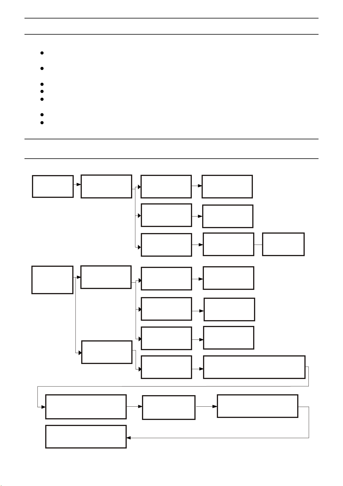
FLOW CHART FOR INSPECTING AND REPAIRING THE UNIT
AIR CO NDITIONER
WON' T START
AIR CO NDITIONER
WON' T COOL
PROP ERLY
NO POW ER
COMP RESSOR WON' T
STAR T
REFR IGERANT
LEAK AGE
POWE R TRIPPED
PLUG A ND SOCKET
ARE LO OSE
TIMER FAILURE
PROT ECTOR FAILU RE
CAPA CITOR FAILU RE
WIRI NG IS LOOSE
TROUBLE SHOOTING
THE SY STEM
CHECK THE POWER
SWIT CH
RE-P LUGING THE
POWE R SUPPLY CORD
TESTIN G BY
ELEC TROSCOPE
CHAN GE THE
PROT ECTOR
CHANGE THE
CAPA CITOR
RE-C ONNECTING
CHAN GE THE AIR COND ITIONER WITH 15 KG/CM
NI TR OGEN GA S FR OM L OW-PR ES SU RE SIDE A ND
DE TE CT THE LE AK IN G POINT B Y SO AP
CHAN GE THE SWITCH
2
USE OX YACETYLEN E AND PLUS 5%
SILV ER SOLDER TO WE LD THE
CRAC KED POINTS
RUNNING TEST
RUNNING THE VACUU M
EVAC UATION FOR MO RE
THAN 1 5 MINUTES
- 1 -
CHANGE COOLANT AN D
PROC EED RUNNING T EST
Page 3
TRO U BLESHOOTING
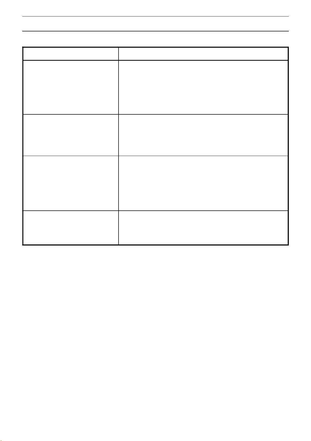
Problem
Does not run
Run a short while
only
Run but not cool
Analysis
·If the protector trip or fuse is blown.
·Please wait for 3 minutes and start again, protector
device may be preventing unit to work.
·If batteries in the remote controller exhausted.
·If the plug is not properly plugged.
·If the set temperature is close to room temperature,
you can low the set temperature.
·Air outlet be blocked by obstacle.
Take the obstacle away.
·If the door or window open.
·If there is other heater appliance work,
like heater or lamp, etc...
·The air filter is dirty, please clean it.
·Air outlet or intake be blocked.
·Set temperature is too high.
Do not run and water
full indicator lights
·Drain the water into a prepared container by the drainage
pipe on the rear panel of the unit.
If still doesn't work, please consult a qualified technician.
- 2 -
Page 4
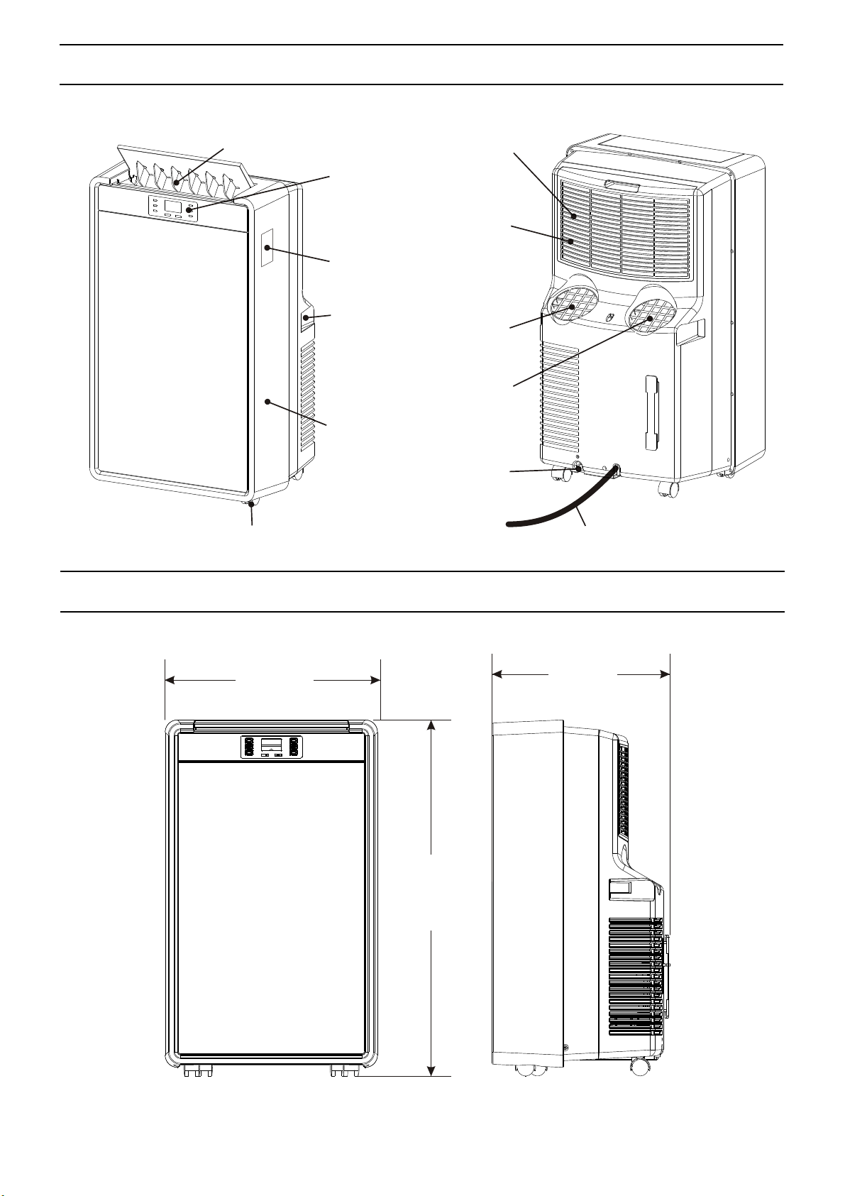
APPEARANCE
Air exhaust for air to be
cooled/filtered
Control panel
Remote control
storage facility
Handles
Front Panel
Air inlet for air to
be cooled / filtered
Air filter
Air outlet
Air inlet
Water drain
Wheels
UNIT DIMENSIONAL
510
Electricity cable
424
855
- 3 -
Page 5
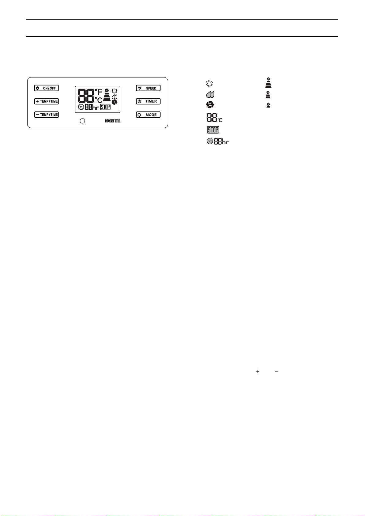
OPERATION
Indication symbols on LCD :
Power Control
The power control turns the unit on and off.
Warning Light
Condensed water may accumulate in the unit. If
the internal tank becomes full, the Warning Light
will shine and the unit will not operate until the
unit has been drained.
Mode Control
The Mode Control has three settings:
● Cool ● Dehumidify ● Fan
The settings are adjusted with Mode Control
button. A light will indicate which setting is
currently being used.
● Cooling Mode
When cool mode is selected, the indicator light
will shine green. During the cooling mode the
air is cooled and hod air is exhausted to the
outside air through the exhaust tube. Adjust fan
speed air through the temperature to suit your
desired comfort level.
Note : The air exchange hoses must vent
outside the room when using cool mode.
● Dehumidify Mode
When dehumidify mode is selected, the indicator
light will shine orange. Air is dehumidified as it
passes through the unit, without being in full
cooling mode. The fan will operate in med speed.
Fan speed is not adjustable in dehumidify mode.
Note : The air exchange hoses must vent inside
the room when using dehumidify mode.
Cooling mod e
Dehumid if y mode
Fan only mo de
Display se t t emperature
Warni ng li ght
the machi ne w ill stop run n ing
Display t im er se ttin g of a uto switch on /off
● Fan Mode
When fan mode is selected the indicator light will
shine yellow. Air is circulated throughout the room
with no cooling.
Note: unit does not need to be vented in Fan
mode
High fan sp ee d
Med fan spe ed
Low fan spe ed
Fan Speed Control
The Fan Speed Control has 3 settings: High,
Medium, and Low.
Timer
Auto turn off :
With machine in fan mode, press timer button to
select number of hours you would like the unit to
run in air conditioning mode until it automatically
shuts off.
Auto turn on :
With machine powered off , press timer button to
select number of hours until you would like the unit
to automatically start running in air conditioning mode.
Timer / Temp set controls
● Used for adjusting the timer and thermostat.
● The default display is room temperature.
● In cooling mode, when " " or " " button is pressed,
the set temperature is displayed and may be adjusted.
After 15 seconds the display will revert back to room
temperature. Temperature is only adjustable in cool
mode. The time is adjustable between 1~24 hours.
Note : By pressing both Timer / Temp set buttons at the
same time, the display will toggle between Celsius and
Fahrenheit.
- 4 -
Page 6
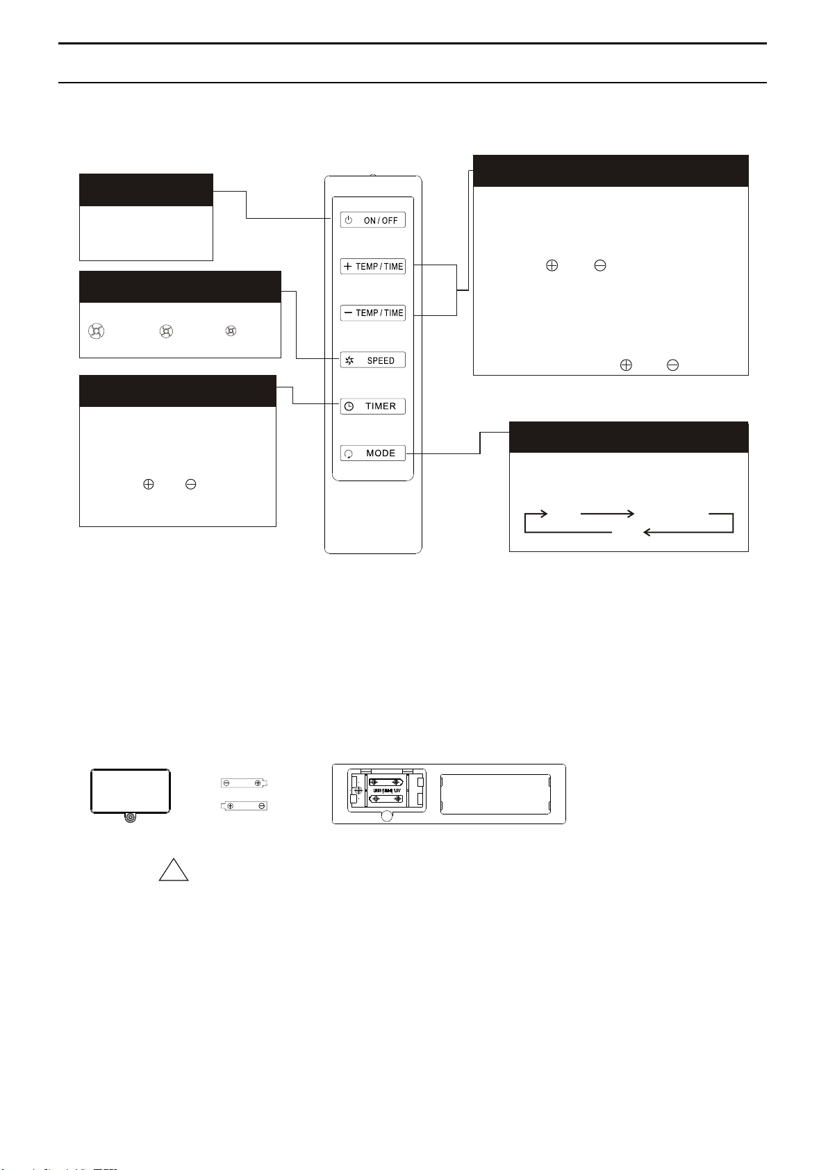
OPERATION
CONTROL PANELCONTROL PANEL
Power ControlPower Control
On / Off
Fan Speed ControlFan Speed Control
:HIG H :MED :LOW
On / Off Timer ControlOn / Off Timer Control
In run ning mode :
Auto sw itch off
In sta nd-by mode :
Auto sw itch on
Pres s " " or " " button
to adj ust the time se tting
for 1 ho ur interval .
Time / Temperature Set Control
● Used for adjusting the timer and
temperature.
● The default display on control panel is
room temperature.
● When " " or " " key is pressed in
cool mode, the set temperature is
displayed and may be adjusted. After
15 seconds the display will revert back
to room temperature.
● Timer setting is available from 1-12 hours
by pressing the key " " on " ".
Mode ControlMode Control
Press this button to change the
operation mode in the order of :
Cool Dehumidify
Fan
Notes
- Do not drop the remote control.
- Do not place the remote control in a location exposed to direct sunlight.
- The remote control should be placed about 1 meter or more away from TV, or any electric appliances.
Battery replacement : Remove the cover on the back of the remote control and insert the batteries with the
( + ) and ( - ) poles pointing in the proper direction.
1.5V1.5V
1.5V1.5V
CAUTION
Use only AAA or IEC R03 1.5V batteries.
Remove the batteries if the remote control is not used for a month or longer.
Do not attempt to recharge the supplied batteries.
All batteries should be replaced at the same time, do not mix old battery .
Do not dispose of the batteries in a fire as they may explode.
!!
- 5 -
Page 7
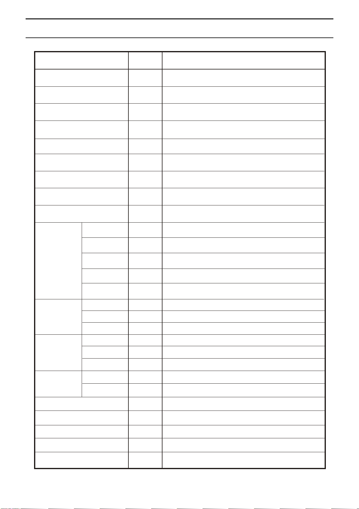
TECHNICAL SPECIFICATIONS
ITEM UNIT
OUTER DIMENSION
REFERENTIAL USING
AREA
RATED VOLTAGE
COOLING CAPACITY
HEATING CAPACITY
DEHUMIDIFYING
CAPACITY
mm
m
V/Hz
B.T.U.
B.T.U.
L/H
RUNNING CURRENT
POWER
CONSUMPTION
MODE L
INPU T
POWE R
COMPRESSOR
OPER ATING
CYCLE
uF/V
A
W
W
WAP-41DR (APN14K)
510W*855H*424D
2
13~19
115 / 60
14000
—
1.8
10.8
—
44N100-A2-BCAD
1007
55/300
PROT ECTOR
MODEL
INDOOR
MOTOR
OUTDOOR
MOTOR
TURBINE
FAN MOTO R
OUTPUT
POWER
OPERATIN G
CYCLE
MODEL
OUTPUT
POWER
OPERATIN G
CYCLE
MODEL
OUTPUT
POWER
CAPILLARY
EVAPORATOR
CONDENSER
REFRIGERANT
W
uF/V
W
uF/V
W
mm
R410A/g
B470-135-241C
LS-23T3-6P
23
8/250
LS-53T1-4P
53
9/250
WT-15T1-02
15
2.6(O.D.)*1.4(I.D.)*1000(L)
2R14S21FPI
(2+1)R17S19FPI
600
WEIGHT
kg
35
- 6 -
Page 8
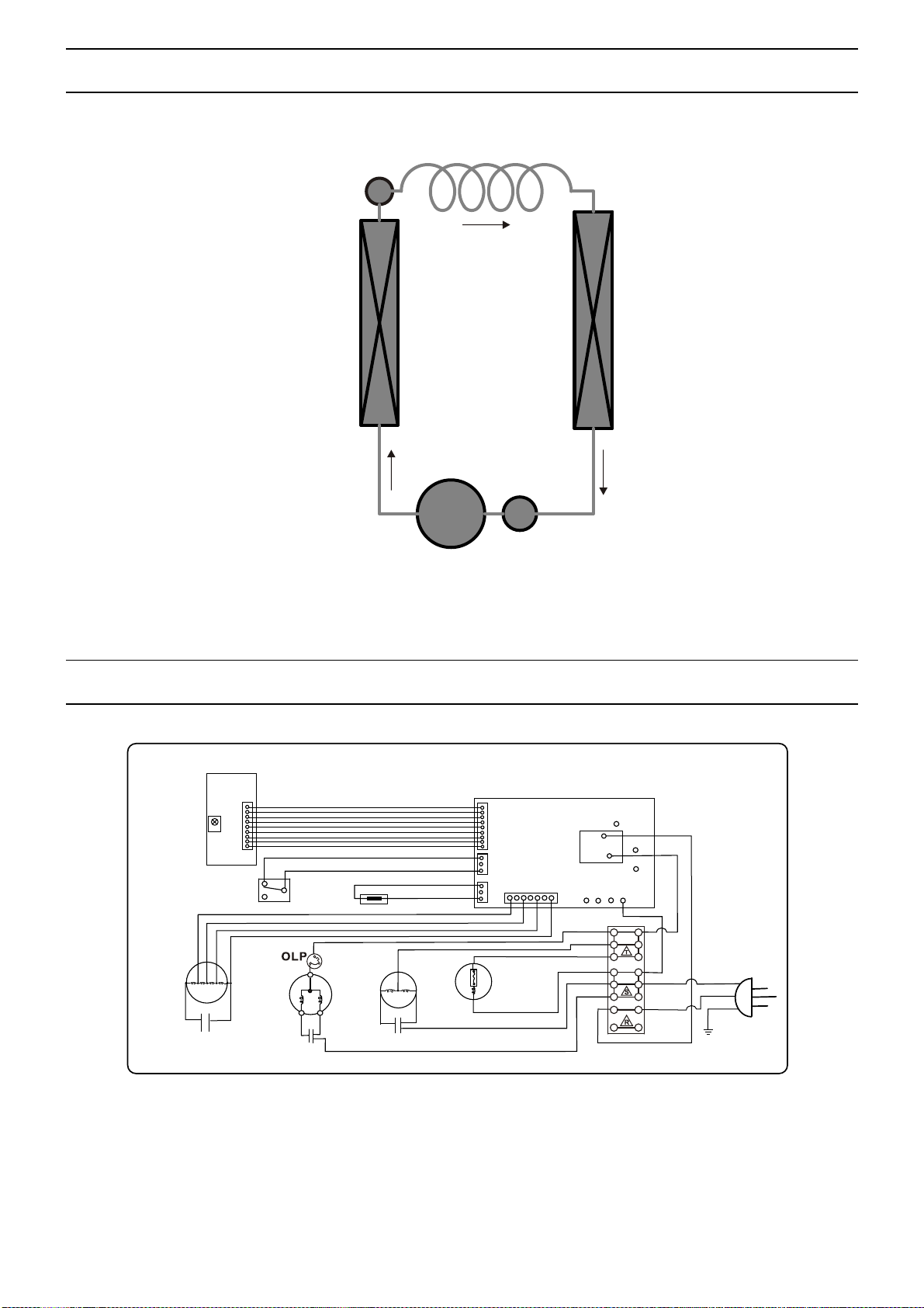
REFRIGERATOR SYSTEM DIAGRAM
CAPILLARY
FILTER
CONDENSOR
COMPRESSOR
SCHEMATI C WIRING DIAGRAM
SCHEMATIC WIRING DIAGRAM
CN1
REM OTE
SEN SOR
MIC ROS .W.
SEN SOR
EVAPORATOR
P7
CN1
CN2
CN4
CN3
COM
NO
P2P1
L
P3
BROWN
P5
RED
P6
P4
IND OOR
MOT OR
WHI TE
CAPACIT OR
COM PRESS OR
BLU E
CAPACIT OR
RED
OUT DOO R
MOT OR
BLU E
WHI TE
BLU E
RED
WHI TE
CAPACIT OR
BLU E
BLU E
RED
WATER
MOT OR
BLU E
BLU E
WHI TE
BLA CK
GRE EN
N
L
E
AC CORD
A695 7-340
- 7 -
 Loading...