


Cabinet unit
Operation Manual
AP162ACMAA
AU162AFMAA
(HPU-16CB03)
AP232ACMAA
AU232AHMAA
(HPU-23CB03)
No.0010573001
A
ON
OFF
EM
HEA H
AN
MODE
S EE
SWNG
C OCK
MER
SE
OCKIGH
RESE
W

Content
Cautions
Parts
Operation
Maintenance
Trouble shooting
When problems occur
Energy saving
Indoor & outdoor unit connection
Tools necessary
Installation procedures
5-16
17-18
19
20
22
23
24-29
1-2
3-4
Content
21

CAUTIONS
Disposal of the old air conditioner
Before disposing an old air conditioner
that goes out of use, please make sure
it's inoperative and safe. Unplug the air
conditioner in order to avoid the risk of
child entrapment.
It must be noticed that air conditioner
system contains refrigerants, which
require specialized waste disposal. The
valuable materials contained in a air
conditioner can be recycled. Contact
your local waste disposal center for
proper disposal of an old air conditioner
and contact your local authority or your
dealer if you have any question. Please
ensure that the pipework of your air
conditioner does not get damaged prior
to being picked up by the relevant
waste disposal center, and contribute
to environmental awareness by
insisting on an appropriate, antipollution method of disposal.
Disposal of the packaging of your
new air conditioner
All the packaging materials employed
in the package of your new air
conditioner may be disposed without
any danger to the environment.
The cardboard box may be broken or
cut into smaller pieces and given to a
waste paper disposal service. The
wrapping bag made of polyethylene
and the polyethylene foam pads
contain no fluorochloric hydrocarbon.
All these valuable materials may be taken
to a waste collecting center and used again
after adequate recycling.
Consult your local authorities for the name
and address of the waste materials
collecting centers and waste paper
disposal services nearest to your house.
Safety Instructions and Warnings
Before starting the air conditioner, read
the information given in the User's Guide
carefully . The User's Guide contains very
important observations relating to the
assembly, operation and maintenance of
the air conditioner.
The manufacturer does not accept
responsibility for any damages that may
arise due to non-observation of the
following instruction.
Damaged air conditioners are not to
be put into operation. In case of doubt,
consult your supplier.
Use of the air conditioner is to be
carried out in strict compliance with the
relative instructions set forth in the User's
Guide.
Installation shall be done by professional
people, don't install unit by yourself.
1

CAUTIONS
Cooling
Indoor
outdoor
Rated Maximum Minimum
27 32 18
19 23 14
35 43 10
24 26 6
DB C
WB C
DB C
WB C
For the purpose of safety, the air
conditioner must be properly grounded
in accordance with specifications.
Always remember to unplug the air
conditioner before opening inlet grill.
Never unplug your air conditioner by
pulling on the power cord. Always grip
plug firmly and pull straight out from
the outlet.
All electrical repairs must be carried
out by qualified electricians.
Inadequate repairs may result in a
major source of danger for the user of
the air conditoiner.
Do not damage any parts of the air
conditioner that carry refrigerant by
piercing or perforating the air
conditioner's tubes with sharp or
pointed items, crushing or twisting any
tubes, or scraping the coatings off the
surfaces. If the refrigerant spurts out
and gets into eyes, it may result in
serious eye injuries.
Do not obstruct or cover the
ventilation grille of the air conditioner.
Do not put fingers or any other things
into the inlet/outlet and swing louver.
Do not allow children to play with the
air conditioner. In no case should
children be allowed to sit on the
outdoor unit.
Specifications
The refrigerating circuit is leak-proof.
Applicable ambient temperature range:
2

Parts
1
2
3
4
Outlet grill
Operation panel
Inlet grill [both side]
Air filter [inside the unit]
Remote-controller
Indoor unit
Outdoor unit
Air inlet
Air outlet
1
3
5
4
2
1
3
5
4
2
1
2
3
4
5
1
2
3
4
5
Drain hose
Air inlet
Connecting hose and
ON
OFF
TEMP
HEALTH
FAN
MODE
SLEEP
SW NG
CLOCK
T MER
SET
LOCKLIGHT
RESET
5
3
W
P

Parts
Manual Operation
Remote controlled operation
MODE
CLOCK
Used to set correct time.
TIMER
LIGHT
Used to set temp.,temp.
range:16 C~30 C
SLEEP
Used to select sleep
mode
HOUR
Used to set clock and
timer setting.
RESET
Used to reset the
controller back to
normal condition.
LOCK
Used to select
TIMER ON, TIMER
OFF, TIMER
ON/OFF.
Used to lock buttons
and LCD display.
Note: Auxiliary heat function is not available.
This model does not have the following related display and function .
ON
OFF
TEMP
HEALTH
FAN
MODE
SLEEP
SWING
CLOCK
TIMER
SET
LOCK
LIGHT
RESET
Power ON/OFF
Used for unit start and stop.
Used to select AUTO run,
COOL, DRY,HEAT and
FAN operation.
2
SET
Used to confirm
Timer and Clock
setting.
TEMP
HEALTH
Control the light up and go
out of the control panel's
background light source and
control the switch of the
buzzer.
Used to set Health
operation function
Fan Speed button
Used to select fan speed:
AUTO, LOW FAN, MED
FAN, HIGH FAN.
Used to set UP/DOWN air
sending and RIGHT/LEFT air
sending direction.
Health display
Display when set Health
operation function.
Battery Capacity display
Display when the electric power of
the battery is insufficient.
Timer ON/OFF display
Fan speed and air sending
direction display
Fan direction display
Room temperature display
Super/Quiet operation display
Humidifying display
Compressor Operation display
Compressor OFF, no display;
compressor ON, full display.
Clock display
Temperature display
Used to display the set temperature
and room temperature.
Lock state display
Working mode display
Sleep state display
Electric Heating display
Fresh Air state display
Working
mode
Auto
operation
Cooling
operation
Dehumidifying
operation
Heating
operation
Fan
operation
Manual
Operation
Remote
controlled
2
SWING
LOW MID HIGH AUTO
1
1
3
3
4
4
5
5
6
6
7
7
8
8
9
9
10
10
11
11
12
12
13
13
14
14
14
15
15
16
16
19
19
17
17
18
18
20
20
20
21
21
22
22
22
23
23
23
24
25
26
24
25
27
26
27
28
29
28 28
29
30
30
30
16
16
15
15
21
4
11
21
22
SOFT
SWING
ON
OFF
POWER
SET
DAMP
TEMP

Operation
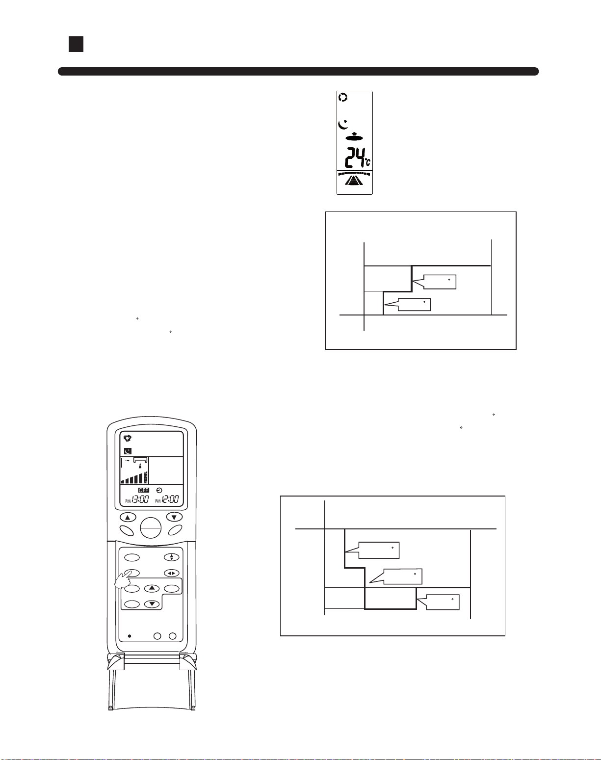
Clock set
When unit is started for the first time
and after replacing batteries in remote
controller, clock should be adjusted as follows:
Press CLOCK button, "AM"or "PM" flashes.
Press or to set correct time. Each press will increase
or decrease 1 min . If the button is kept depressed, time
will change quickly.
After time setting is confirmed, press SET, "AM" and "PM"
stop flashing, while clock starts working.
Remote controller's operation
When in use, put the signal transmission
head directly to the receiver hole on the
indoor unit
The distance between the signal transmission
head and the receiver hole should be within
7m without any obsacles as well.
Don't throw the controller
, prevent it from
being damaged.
When electronic-started type fluorescent
lamp or change-over type fluorescent lamp
or wireless telephone is installed in the room,
the receiver is apt to be disturbed in receiving
the signal
so the distance to the indoor unit should be
shorter.
Loading of the battery
Slinghtly press " " and push down the cover.
Load the batteries as illustrated.
2 R-03 dry batteries, (cylinder)
Be sure that the loading is in line with the "+"/"-" pole
request as illustrated.
Put on the cover again
Confirmation indicator:
In disorderation, reload the batteries or load the new batteries after 5 mins.
Note:The waster batteries should be disposed properly,use two new same-type batteries when loading.
If the remote controller canít function normally or doesnít work at all,use a sharp-pointed item to pres
the reset key
.
Hint:Remove the batteries in case unit wonít be in usaged for a long period.
If there are any displays after taking-out just need to press re
set key.
MODE
S EE
SWNG
C OCK
IMER
SE
OCKIGH
RESE
2R-03 dry batteries
1
2
3
5

Operation
Auto
Manual
Remote-control unit
AUTO COOL DRY HEAT
2
1
Press ON/OFF button
Unit starts running.
The previous status appears on the display
(except.
TIMER, SLEEP and SWING mode)
Press MODE button. For each press,
operation mode changes as follows:
3
Manual
Remote
controller
FAN
AUTO COOL DRY FAN HEAT
Press ON/OFF button
Unit stops running.
4
Select Auto run,
" " appears and auto run starts.
Press FAN,For each press, operation mode
changes as follows:
Remote
controller
LOW MID HIGH AUTO
ON
OFF
TEMP
HEALTH
FAN
MODE
LEEP
SWING
CLOCK
TIMER
SET
LOCKL GHT
RESET
2
4
Unit runs at the speed displayed on LCD.
When fan speed is AUTO,it is changed outomatically
according to the indoor temperature.
Manual find it in page 20
Note:
During Auto run operation, temp. setting will not be shown in LCD display, unit will select heating, cooling
or fan operationaccording to the room temp.
1
3
6
TEMP
SWING

Operation
Cooling
Manual
Press ON/OFF button
Unit starts running.
The previous status appears on the display
(except.
TIMER, SLEEP and SWING mode)
Press MODE button. For each press,
operation mode changes as follows:
Select temp. button
Press
TEMP button
Every time the button is pressed, temp.
setting increases 1 C
Every time the button is pressed, temp.
setting decreases 1 C
If the button is kept pressed, setting will
increase or decrease quickly.
Press ON/OFF button
Unit stops running,and when entry this mode for the
next time,it will show the previous setting.
Unit runs at the speed displayed on LCD.
When fan speed is AUTO,it is changed outomatically
according to the indoor temperature.
5
3
2
1
Select cooling operation, Shows" "
Cooling operation starts.
Press FAN button. For each press, fan speed
changes as follows:
4
Remote-control unit
Remote
controller
AUTO COOL DRY HEAT
Manual
Remote
controller
FAN
AUTO COOL DRY FAN HEAT
Manual find it in page 20
LOW MID HIGH AUTO
ON
OF
TEMP
HEALTH
F N
MODE
LEEP
SWING
CLOCK
TIMER
SET
LOCKLIGHT
RESET
1
2
3
5
3
4
7
TEMP
SWING

Operation
Dry
Manual
Press ON/OFF button
Unit starts running.
The previous status appears on the display
(except.
TIMER, SLEEP and SWING mode)
Press MODE button. For each press, operation mode changes
as follows:
Select Drying operation shows" "
Dry operation starts
Select temp. button
Press
TEMP button
Every time the button is pressed, temp. setting increases 1 C
Every time the button is pressed, temp. setting decreases 1 C
If the button is kept pressed, setting will increase or decrease
quickly.
Press FAN button. For each press, fan speed changes as
follows:
Press ON/OFF button
Unit stops running, and when
entering this mode for the next
time, it will show the previous setting
Unit runs at the speed displayed on LCD.
In DR
Y mode, when room temp.becomes 2 C higher than temp.
setting,unit will run intermittently at LOW speed regardless of FAN
setting.
3
2
1
4
5
Ultra-low air flow
Temp.setting+2 C
Temp.setting
On reaching 2 C higher than temp.
setting,unitwill run in mild DR
Y mode.
COOL operation starts when room
temp. is higher than temp. setting.
Remote-control unit
ON
OF
TEMP
HEALTH
N
MODE
LEEP
SWING
CLOCK
TIMER
SET
LOCKLIGHT
RESET
1
2
3
AUTO COOL DRY HEAT
Manual
Remote
controller
FAN
AUTO COOL DRY FAN HEAT
Remote
controller
LOW MID HIGH AUTO
Manual find it in page 20
5
3
4
8
TEMP
SWING

Operation
Fan
Manual Operation
Press ON/OFF button
Unit starts running.
The previous status appears on the display
(except.
TIMER, SLEEP and SWING mode)
Press MODE button. For each press,operation mode
changes as follows:
Select Fan operation shows " ", Fan operation starts.
Press ON/OFF button
Unit stops running, and when entering this mode for the
next time, it will show the previous setting.
4
1
2
3
Press FAN button. For each press, fan speed changes as
follows:
Note:
In this mode, temp. can't be selected, temp.setting will not be
show in LCD display
.In Fan operation mode, "AUTO" fan speed
is not available. Operation cycles are as follows:
LOW MID HIGH
Remote-control unit
AUTO COOL DRY HEAT
Manual
Remote
controller
FAN
AUTO COOL DRY FAN HEAT
Unit runs at the speed displayed on LCD.
Remote
controller
LOW MID HIGH
ON
OFF
TEMP
HEALTH
FAN
MODE
LEEP
SWING
CLOCK
TIMER
SET
LOCKL GHT
RESET
1
2
3
4
9
TEMP
SWING

Operation
Heating
Manual
Press ON/OFF button
Unit starts running.
The previous status appears on the display
(except.
TIMER, SLEEP and SWING mode)
Press MODE button. For each press,operation mode
changes as follows:
Select Heating operation " " appears and Heating
operation starts.
Press FAN button. For each press, fan speed changes as
follows:
4
1
2
3
Select temp. button
Press
TEMP button
Note: For cooling only type, this function is invalid.
Every time the button is pressed, temp. setting increases 1 C
Every time the button is pressed, temp. setting decreases 1 C
If the button is kept pressed, setting will increase or
decrease quickly
.
Press ON/OFF button
5
Unit stops setting when entering this mode next time.
In heat mode,warm air will blow out after a short period of
time due to cold-draft prevention function.
Remote-control unit
AUTO COOL DRY HEAT
Manual
Remote
controller
FAN
AUTO COOL DRY FAN HEAT
ON
OF
TEMP
HEALTH
FAN
MODE
LEEP
SWING
CLOCK
TIMER
SET
LOCKLIGHT
RESET
1
2
3
Remote
controller
LOW MID HIGH AUTO
Manual find it in page 20
4
5
3
10
TEMP
SWING

Operation
Air flow adjustment
Swing louvers
(Vertical louvers)
Up and down
Adjust the louvers by hand to proper position.
Put louvers at up position in cooling and down position in heating mode.
This will be helpful to keep an even room temp.
Note:
In cooling or dry operation, don't put horizontal louvers at downward
position for a long time, or outlet grill might get frosted. Don't expose
your skin to cool or warm air for a long time.
Notice:
Side from side
Swing
Press SWING " " or " "
appears on the display, the vertical
louvers move from side to side.
Fixed position
Press the SWING again to fix the
vertical louvers at your desired position.
Side from side
ON
OFF
TEMP
HEALTH
FAN
MODE
SLEEP
SWING
CLOCK
TIMER
SET
LOCKLIGHT
RESET
2
1
Position 1
Position 2
Position 3
Position 4
Position 5
Position 6
Position 7
Position 8
[COOL/DRY/FAN
/AUTO(COOL)
HAVE NOT]
(AUTO
SWNG)
Position 1
Position 2
Position 3
Position 4
Position 5
Position 6
11
TEMP
SWING
Operation
SLEEP
Remote control unit
Usage of the Sleep function
After starting, set the Run mode and press the Sleep
button.
Run mode
1. In cooling and dry
After starting of the Sleep operation, the temperature Will
be raised for 1 C higher than the set temperature 1 hour
later
,and be raised for 1 C after another hour. It continues
under that condition for 6 hours, then the machine will be
switched off. The temperature is higher than the set
temperature so as to avoid catching cold in sleeping.
2. In heating ( the single-cooling conditioners do not have the
function)
After the Sleep running starts, the temperature will drop for 2 C after
another one hour
. The temperature will raise for 1 C after 3 hours
running under the above temperature, and the conditioner will be
closed down after running for 3 hours. The temperature is lower
than the set temperature so as to avoid uneasiness in sleeping.
3. In automatic running
The conditioner will run under automatically selected working
mode of sleeping.
4. In Fan running
The Sleep function is invalid.
About 6 hours
The Sleep running starts The Sleep running stops
Set the
temperature
Closc down
the machine
In cooling and dry
Raise 1 C
Drop for 2 C
Drop for 2 C
About 3 hours
The Sleep running starts
The Sleep running stops
Set the
temperature
Close down
the machine
In heating
1 hour
Raise 1 C
1 hour
Raise 1 C
1 hour
1 hour
3 hours
Manual
ON
OFF
TEMP
HEALTH
FAN
MODE
SLEEP
SWING
OCK
TIMER
SET
LOCKLIGHT
RESET
Before go to bed, you can press the Sleep button,
the air conditioner will operate in comfortable
sleep mode to make your sleep more comfortable.
12
EMP
SW NG

Operation
Timer on/off operation
Manual
Remote control unit
TIMER operation
Set Clock correctly before starting Timer operation (refer to page 5)
Y
ou can let unit start or stop automatically at following times: Before you wake up in the morning, or get back
from outside or after you fall asleep at night.
TIMER ON/OFF
(1) After unit start, select your desired operation mode.
Operation mode will be displayed on LCD.
(2) TIMER mode selection
Press TIMER button to change TIMER mode.
Every time the button is pressed, display changes as follows:
Remote
controller
Select your desired TIMER mide (TIMER ON or TIMEROFF) ON or OFF
will flash.
(3) Timer setting
Press HOUR / button.
Every time the button is pressed, time increases 10 min, If button is kept
pressed, time will change quickly
.
Every time the button is pressed, time decreases 10 min, If button is
kept pressed, time will change quickly. Time will be shown on LCD. It can
be adjusted within 24 hours.
(4) Confirming your setting
After setting correct time, press SET button to confirm, " "
or " " stops flashing.
T
ime displayed: Unit starts or stops at x hour x min (TIMER
ON or TIMER OFF)
Timer mode indicator on indoor unit lights up.
To cancel TIMER mode
Just press TIMER button several times until TIMER mode disappears.
Hints
After replacing batteries or a power failure happens, Time setting should be reset.
Remote controller possesses memory function when use
TIMER mode next time, just Press SET button after
mode selecting if timer setting is the same as previous one.
ON ONOFF OFF
TIMER ON TIMER OFF TIMER ON-OFF
AM
12:00
PM
12:00
PM
12:00
AM
12:00
BLANK
ON
OFF
ON
OFF
TEMP
HEALTH
FAN
MODE
SLEEP
SWING
OCK
TIMER
SET
LOCKLIGHT
RESET
13
TEMP
SWING

Operation
Timer on-off function
Manual
Remote controller operation TIMER ON-OFF
(1) After unit start, select your desired operation mode.
Operation mode will be displayed on LCD.
(2) TIMER mode selection
Press TIMER button to change TIMER mode.
Every time the button is pressed, display changes as follows:
(3) Timer setting for TIMER ON
Press HOUR button.
Every time the button is pressed, time increases 10 min. If button is
kept pressed, time will change quickly.
Every time the button is pressed, time decreases 10 min. If button
is kept pressed, time will change quickly.
Time will be shown on LCD.
It can be adjusted within 24 hours.
AM refers to morning and PM to afternoon.
(4) Time confirming for TIMER ON
After time setting, press TIMER button to confirm," " stops blinking,
while " " starts blinking.
Time displayed: Unit starts or stops at x hour x min
To cancel TIMER mode
Just press TIMER button several times until TIMER mode disappears.
ON
Remote
controller
ON ONOFF OFF
TIMER ON TIMER OFF TIMER ON-OFF
AM
12:00
PM
12:00
PM
12:00
AM
12:00
BLANK
OFF
(5) Time setting for TIMER OFF
Follow the same procedure in "Time setting for TIMER ON".
(6) Time confirming for TIMER OFF
After time setting, press SET button to confirm, " " stops flashing.
Time displayed: Unit stops at x hour x min
OFF
According to the Time setting sequence of TIMER ON or TIMER OFF,either ON-OFF or OFF-ON can be
achieved.
Select your desired TIMER mide (TIMER ON or TIMEROFF) ON or OFF
will flash.
2
3
4
5
6
1
14
ON
OFF
TEMP
HEALTH
FAN
MODE
SLEEP
SWING
CLOCK
TIMER
SET
LOCK
LIGHT
RESET
TEMP
SWING

Elliptoid Curve
(From inside to outside 1 to 8 section one after another)
When adjusting fan speed in unit operation, each press of the Fan Speed
button of the remote controller
, the fan speed will change in the following
sequence:
, where
Remote controller:
Control panel: the radial straight line and elliptoid curve circularly flash and roll,
for the specific is as follow:
The radial straight line displays following Swing
Elliptoid Curve
(From inside to outside 1 to 8 section one after another):
AUTO:
Section 1
goes out
Others light
up
Section 2
goes out
Others light
up
Section 3
goes out
Others light
up
Section 8
goes out
Others light
up
LOW FAN:
Section 1
lights up
Others go
out
Section 1~ 2
light up
Others go
out
Section 1~
3 light up
Others go
out
Section 1
lights up
Others go
out
Section 1~ 2
light up
Others go
out
Section 1~ 3
light up
Others go
out
Section 1
lights up
Others go
out
Section 1~ 2
light up
Others go
out
Section 1~ 3
light up
Others go
out
HIGH FAN:
MED FAN:
Function display
Press the Lighten button of the remote controller, each press, the control panel LCD
display will change in the following sequence:
Operation
Fan Speed display
Fan Speed display
......
Total
lignt up
The curve section point
lights up, low speed
......
......
......
OFF
ON
Total
lignt up
Total
lignt up
The curve section point
lights up, medium speed
The curve section point
lights up, high speed
15
ON
OFF
EM
HEA H
AN
MODE
S EE
SWNG
C OCK
IMER
SE
OCKGH
RESE
AUTO
LOW FAN
MED FAN
HIGH FAN
AUTO
LOW FAN
MED FAN
HIGH FAN
The background light
source lights up
The buzzer does not
sound
The background light
source lights up
The buzzer sounds
The background light
source does not light up
The buzzer sounds
TEMP
SWING

o
o
Operation
When room temperature is below 16 C and perform cooling test run, use test run function.
Do not use it in normal state.
Used in cooling test run of room
temperature below 16 C.
Do not use it in normal state.
Press the test run switch and depress for over 5
seconds.
After hearing the air conditioner give two
sounds, then release pressing.
At this time, the test run starts.
The air conditioner runs in High Fan Speed.
Press the test run switch once, can hear the suggestive OFF sound.
Press once the ON/OFF button of the remote controller, can hear the suggestive OFF sound.
The air conditioner will operate in the working mode displayed o
n the remote controller.
Use remote controller to cancel test run
Turn off the unit (Cancel test run)
Turn on the unit
Test run
Test Run
Each time when cut off power and re-powered on, after the full-screen display for 5
seconds, it will display the room temperature.
Press ON/OFF and T
emperature+/- button, the air conditioner will give musical suggestive
sound.
Test run Switch
Fan Speed
Mod
Temperature+
Temperature-
ON/OF
16

Maintenance
Disconnect power supply Don't touch it with wet
hand
Don't wash with hot water
or solvent to clean the unit
Don't use hot water over 40 C,
as this may cause damage to air filter.
Wipe air filter carefully.
Clean it with warm and wet cloth or with neutral detergent, then wipe it dry with
clean and soft cloth.
If air conditioner is very dirty
, clean it with cloth
soaked in neutral detergent,then wipe off the
detergent with clean water.
Don't use water higher than 40 C , which will cause
discoloring and deformation.
Don't use insecticide or other chemical detergents.
Caution:
Indoor and outdoor cleaning
Use water or vacuum cleaner to clean it.
If it is extremely dirty, wash it with
neutral detergent or soap water.
Wash it with clean water and install
it after complete dry
.
Air filter cleaning
40*
Pull it out from top as shown in Fig.
40*
Remove air inlet grille
17

Maintenance
After season maintenance
Before season maintenance
Trouble shooting
Followings are not problems
Let the unit run in Fan mode for half a day in a
fine weather to dry completely the unit inside.
Clean air filter and indoor unit,
cover outdoor unit after
cleaning.
Turn off the unit and pull out
power plug.
There might be certain power
consumption even if unit is stopped.
Check if there are obstacles at inlet and outlet of indoor and outdoor unit,
whick will reduce unit ef
ficiency.
Don't fail to attach air filter after making sure it is cleaned.
Dust will enter into unit causing damages or faults if it is
running without air filter
.
To protect compressor at start, please connect external
power supply to the unit 12 hrs prior to starting.
Also
please keep the power supply switch ON during the whole season.
Sound of water flowings are not
problems.
During unit start and operation or at stop, a swishing
or gurgling noise may be heard.
This noise is
generated by refrigerant flowing in the system.
Sound of cracking is heard.
During unit operation, a cracking noise may be heard.
This noise is generated by the casing expanding or
shrinking because of temperatuer changes.
Smells are generated.
This is because the system circulates smells from
the interior air such as the smell of cigarettes or the
painting on the unit.
During operation, white fog or steam
comes out of indoor unit.
When unit is running at places like restaurant where
dense edible oil fumeis always exist, this will happen.
In cooling operation, unit switches to fan
operation.
To prevent frost from accumulating on indoor heat
exchanger, unit will switch to fan operation for a
while then resume cooling operation.
18

Trouble shooting
Followings are not problems
Unit will not restart after stop.
Won't start?
No outlet air or fan speed can't be changed
in dry mode.
In heating operation, water or steam are blown
out of indoor unit.
In heating operation, indoor fan won't stop even
if unit is stopped.
Though ON/OFF button is set to ON, unit won't resume
cooling,dry or heating operation in 3 min after it is stopped,
this is because of 3-min-delay protection circuit.
Unit will reduce fan speed repeatedly and automatically
if room temp. is too low in dry operation.
This occurs when frost accumulated on the outdoor unit
is removed.
(during defrosting operation)
After unit stops, indoor fan will go on running until indoor
unit cools down.
Please wait 3 minutes
19

When problems occur?
Air conditioner won't start.
Before ask for services, please first check your unit against following.
Is power supply switch
turned on?
Power supply switch is not
set at ON.
Are operation controlls
adjusted correctly
as specified?
Are horizontal louvers
at up position (in
heating mode)?
Is there any direct sunlight
in the room?
Poor cooling or heating
Poor cooling
Is city power supply normal?
Is air filter too dirty?
Any doors or windows left
open?
If there are unexpected heat
sources in the room?
Are there any obstacles at inlet
or outlet grill?
Too many people in the room?
Is leakage current breaker
activated?
This is very dangerous, please
disconnect power supply
immediately and contact your
dealer
.
If your unit still can't work properly after above mentioned checks, or following problems occur,
please stop it immediately and contact your dealer
.
Fuses or circuit breakers often blow out.
Water comes out in cooling/dry operation.
Operation is abnormal or sound is heard.
Power
failure?
If the fuse on PC board is broken please change it with the type of T.3.15A/250V.
20

Energy saving
Keep proper room temp.
Too cold or too warm is no good to
your health, and power consumption
will be increased as well.
Air filter should be periodically cleaned
If air filter is clogged:
It will cause poor cooling and
heating ef
ficiency, higher power
consumption and even problem may
occur. In cooling operation,water will
flow out.
Use Timer effectively
You may use Timer mode to keep a
comfortable room temp.when you
wake up or come home from outside.
Avoid direct sunlight
and air flow
Adjust air flow
properly
proper room
temp.
21

Indoor & outdoor unit connection
Over 10cm
Over 10cm
Over 10cm
Over 100cm
pipe direction
Left
Rear
Right
Bottom
Over 10cm
Over 10cm
Over 60cm
Over 15cm
Over 10cm
Over 10cm
Over 60cm
Over 15cm
AU162AFMAA
AU232AHMAA
22

Tools necessary
Tools necessary
Remote controller
Cement nail
Drain hose
Heat-insalution pipe
L-shaped metal
Fall-prevention fitting metal
Wire clip
Drain elbow
Self-tapping scerw
Rubber pad
Wall hole cover
Piping hole cover
No. QTY
Shape and description
Parts in the following list are accessories for
the unit installation which can be used if necessary
.
Standard accessories
1. Screw driver
2. Hacksaw
3. 70mm dia. hole core drill
4. Spanner (dia. 17, 27mm)
5. Spanner (14, 17, 19, 27mm)
6. Pipe cutter
7. Flaring tool
8. Knife
9. Nipper
10. Gas leakage detector or soap
water
1
1. Measuring tape
12. Reamer
Following parts shall be field supplied
16
15
14
13
12
11
10
9
7
6
5
4
3
2
1
1
1
3
2
2
4
4
1
3
1
1
1
8
For cooling only type.drain elbow is not
available
1
1
Adhesive tape
Connect unit wire
Connect pipe
Ventilation pipe
(3 long and 1 short)
Joint of ventilation pipe
Protection cover of ventilation pipe
(2 lar
ge and 1 small)
Side panel air inlet grille
Side panel air filter
17
18
19
20
21
Dry battery 7
#
2
2
4
3
1
1
Remarks:
(1) For side panel air inlet grille and air filter
, model
16 has 1, model 23 has 2.
(2) a: For model 16, the side panel air inlet grille and
air filter are installed on the premade rounded
hole of either right or left side panel;
b: For model 23, when the premade rounded hole
of right/left side panel is not occupied by
connecting pipe, the two holes shall be installed
with side panel air inlet grille and air filter; if
one of the premade holes is occupied by
connecting pipe, the side panel air inlet grille
and air filter shall be installed in the non occupied rounded hole and the premade hole of
rear protection panel.
Mark
Parts name
Adhesive tape
Pipe clip
Connecting hose
Insulation material
Putty
Drain hose
A
B
C
D
E
F
23

Installation procedures
Display of whole unit
Installation of outdoor unit
Installation dimension of outdoor unit (mm)
Try to bring the packed unit to the installation place.
When it is inevitable to unpack the unit, be careful not to damage the unit. Wrap it with
nylon etc.
After unpacking, be sure to put it with the front side of the unit facing up.
Note: When delivering, don't hold plastic
parts like inlet and outlet grill etc.
Selection of installation place
Place strong enough to support the unit and will not cause vibration and noise.
Place where discharged wind and noise doesn't cause a nuisance to the neighbors.
Place where is less affected by rain or direct sunlight and is sufficiently ventilated, or
to install a shield.
Place with enough space for smooth air flow.
Fixing of the unit
Fix outdoor unit using M10 bolt to concrete floor horizontally.
If installed on the wall or on top of a roof, bracket should be fixed securely to resist
earthquake or storms.
Use rubber pad during installation against unit vibration.
Delivery
Facing up
Do not install the air conditioner on the non-special metal bracket (e.g. theft
guarding net).
If outdoor unit is street installed, it cannot be lower than 2.5m
Use expansion bolt (M10) to fix the outdoor unit installation bracket on the wall.
Use bolt (M10) and nut to fix the outdoor unit on the installation bracket and keep
horizontal.
The air outlet of outdoor unit shall be no less than 3m away from the neighbors. If
necessary, it shall get the neighbor's agreement.
HPU-16CB03
140 140500
256
HPU-23CB03
24

Installation procedures
Installation of indoor unit
Selection of installation place
Place where it is easy to route drainage pipe and outdoor piping.
Place away from heat source and with less direct sunlight.
Place where cool and warm air could be delivered evenly to every corner of the room.
Place near power supply socket. Leave enough space around the unit (refer to installation
drawings).
Fixing of the unit
Position of the wall hole
W
all hole should be decided according to installtion place and piping direction. (refer to
installation drawings)
Making a wall hole
Drill a hole with a little slope towards outside.
Install piping hole cover and seal it with putty after installation.
1.
2.
Fixing of indoor unit
To prevent it from fall off, please fix the unit with fall-prevention fitting at wall and Lshaped metal at floor
.
Self-tapping
screw
all-prevention fitting metal (accessory)
Wood screw
L-shaped metal
(accessory)
Please install the whole unit horizontally ,
with a slop of 1 degree at front and rear
,
left and right.
INDOOR
OUTDOOR UNIT
wall hole
wall thinkness
( Cross section of wall hole )
wall hole
( Frone section of wall hole )
Select the place where is firm, not easy to vibrate and can bear the weight of the unit.
When installed in bedroom, it is not suitable to let the air blow directly to the bed.
25
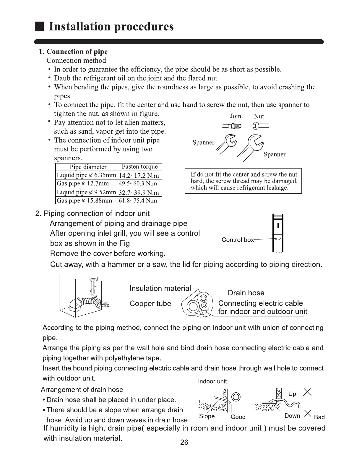

3. Piping connection of outdoor unit.
Connect the connecting pipe and inlet and outlet liquid pipe according to the piping
method.
Installation procedures
When piping is longer than 5 m, charge additional refrigerant specified in this list.
Pipe length
Refrigerant charge (g)
5m 10m 15m
18090
4.Purging method
Discharge the air out of the indoor unit and the refrigerant pipe by vacuumizing
5.Extra charging amount of the refrigerant
o
(1) Remove the valve cap of 2-way valve of outdoor unit.
(2) Loosen the flare nut connecting to 3-way valve thick pipe 1~1.5 circuit.
(3) Use spanner (hexagon spanner) to loosen 2-way valve core 90
. About 15 seconds later, tighten
2-way valve. The air will discharge out from the flare of thick pipe. When there is no air
discharge, tighten the flare nut according to the specified torque.
(4) Open 2-way valve and 3-way valve.
(5) Tighten the valve cap of the two valves.
(6) Use leakage detector or soap water to check whether there is leakage.
According to the Figure shown method, remove the air in indoor unit and connecting pipe.
Note:
When lengthen the connecting pipe, firstly use non-system Freon R22 to remove the air in the
connecting pipe, then use the above air dischar
ging method to remove the excessive refrigerant.
The newly released air conditioner has been charged extra 80g R22 on the base of the
previously specified refrigerant amount.
This method is only for the first-time installation to remove the air in connecting pipe and
indoor unit.
15 88mm (5/8")
3-way valve
Gas pipe
9 52mm (3/8")
2-way valve
Liquid pipe
HPU-16CB03
Liquid pipe
6 35mm (1/4")
Open
3-way valve
2-way valve
90*
Gas pipe
12 70mm (1/2")
HPU-23CB03
Specified torque:
Specification
Torque
Valve core
Valve cap
Tighten torque N m
27
(Sketch map)
Installation procedures
Power cord
(User self-provided)
Special switch over 30A
(The parts in dotted line are user self-provided)
2
2
2
Electric wiring
2.The wiring method of straight terminal
For those connection wires whose end are not orbicular terminals, their
wiring method is:
Loosen the connecting screw, insert the end of the wire directly into the terminal
block, and then tighten screw. Pull the wire outwards slightly to confirm it is held
tightly.
3.Pressing method of connection wire:
After wiring, the connection wire must be
pressed with wire holding clamp. The wire
holding clamp should press on the out co ver of the connection wire. As the right fi gure shown:
Wiring method
1.The wiring method of orbicular terminal
For the connection wire which end is orbicular
terminal, its wiring method is as the right figure
shown. Dismantle the screw and put it through
the ring at the end of the connection wire, then
connect it to the terminal block and tighten the
screw.
The wiring method of orbicular terminal
Correct pressing
Terminal block
Wire holding clamp
Wrong pressing
4. Lengthen power cord
It must use a whole piece of power cord when it is lengthened.Do not lengthen by
connection. When lengthen feeble current signal wire, the connecting wire must be
100mm staggered and welded firmly.
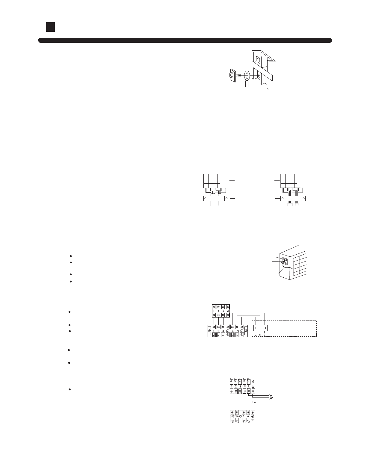
Wire connecting of outdoor unit
Remove the electric box cover.
Connect the connecting wire properly according to wiring
method and wiring diagram of indoor & outdoor unit.
Press the connecting wire properly according to the
connecting wire pressing method.
Reinstall the electric box cover.
Terminal
Wire holding
clamp
Pre-remained wire
Wire connecting of indoor unit
Remove the air inlet grille and open the
control box cover.
Introduce the front end of connecting wire out.
Connect the connectign wire properly according
to wiring method and wiring diagram of indoor &
outdoor unit.
Press the connecting wire properly according to
connecting wire pressing method.
Reinstall the control box cover and air inlet grille
properly.
Power supply: 1PH,220V~,50Hz, and is connected from
outdoor unit.
HPU-16CB03
Indoor unit casing
Terminal block (outdoor)
Terminal block (indoor)
Power : 1PH,220-230V~,50Hz
HPU-23CB03
Terminal block (outdoor)
Terminal block (indoor)
Power : 1PH,220-230V~,50Hz
Note:
The electric wire must be copper-core wire.
Tyep of connecting wire: YZW.
Power supply: 1PH,220V~,50Hz, and is connected from
indoor unit.
KF-48LW/K(XF):
3x2.0mm 2x0.75 mm
KF-68LW/K(XF):
4x0.75 mm
28

Installation procedures
Installation inspection and test run:
Please operate unit according to this Manual.
Items to be checked during test run. Please made a " "in " "
Are there any gas leakage?
How is insulation at piping connection carried out?
Are electric wires of indoor and outdoor unit firmly inserted into terminal block?
Is electric wiring of indoor and outdoor securely fixed?
Is draminage securely carried out?
Is earth line ( grounding ) securely connected?
Is power supply voltage abided by the code?
Is there any noise?
Is control display normal?
Is cooling operation normal?
Is room temp. regulator normal?
Other instruction and test run
Other instruction
1.Power supply
The air conditioner must use a special power circuit and special air switch.
The air switch should be all-pole switch,and the distance between its two
contacts should be no less 3mm.
The users should provide special switch, grounding wire by themselves.
The wiring should be done by a qualified electrician according to the wir ing rules specified by national standard
An creepage breaker should be installed.
The grounding wire and null wire of receptacle should be strictly separated.
It is incorrect to connect the null wire with grounding wire.
The connection method of power cord is Y connection. If the power cable
is damaged,in order to avoid danger, it must be replaced by the manufacturer
or its specified repair center of the same qualified worker.
All the wires should be copper core wires.
2. Cut and flaring method
Use pipe cutter to cut the pipe,
the burrs must be removed.
After inserting the flarer, perform
flared nut.
Pipe diameter
Liquid pipe
Dimension A (mm)
6.35mm (1/4î)
0.8-1.5
Connect pipe
Gas pipe
1.0-2.0
12.7mm (1/2î)
Flaring dimensions as follows:
Test run
Liquid pipe
9.52mm (3/8î)
1.0-1.2
Gas pipe
1.4-2.2
15.88mm (5/8î)
Incorr
Slant
Broken
Uncompleted
Burrs Too long
Correct
Flarer
A
29
 Loading...