

Haier AMS24H03-N, HSU-24LE03(T3), AMS30H03-N(T3), HSU-24LEA13-M, HSU-30LEA03(T3)-IR Operation Manual
Please read this operation manual before using the air conditioner.
Keep this operation manual for future reference.
SPLIT TYPE ROOM AIR CONDITIONER
OPERATION MANUAL
0010518784
Contents
1
2-4
5
7
6.7
CAUTIONS
PARTS AND FUNCTIONS
OPERATION
MAINTENANCE
TROUBLE SHOOTING
HSU-24HEA03(T3)
HSU-24HEA13(T3)
HSU-24LEA13(T3)
HSU-24LEA03(T3)
HSU-32LEA13-W
AMS30H03-N(T3)
PAS24L03-N(T3)
HSU-24LEA03-T
HSU-30HEA03(T3)
HSU-30HEA13(T3)
HSU-24LEB03(T3)
HSU-36LEA03(T3)
PAS30H03-N(T3)
HSU-18LEB03(T3)
HSU-30LEA13(T3)
HSU-28LEA03(T3)
HSU-30LEA03(T3)
HSU-30HEA03
HSU-24HEA03
HSU-24LEA03
HSU-24LEA13-M
HSU-26HEA03
HSU-24LE03(T3)
AMS24H03-N
HSU-30LEA03(T3)-IR
POWER/SOFT
1
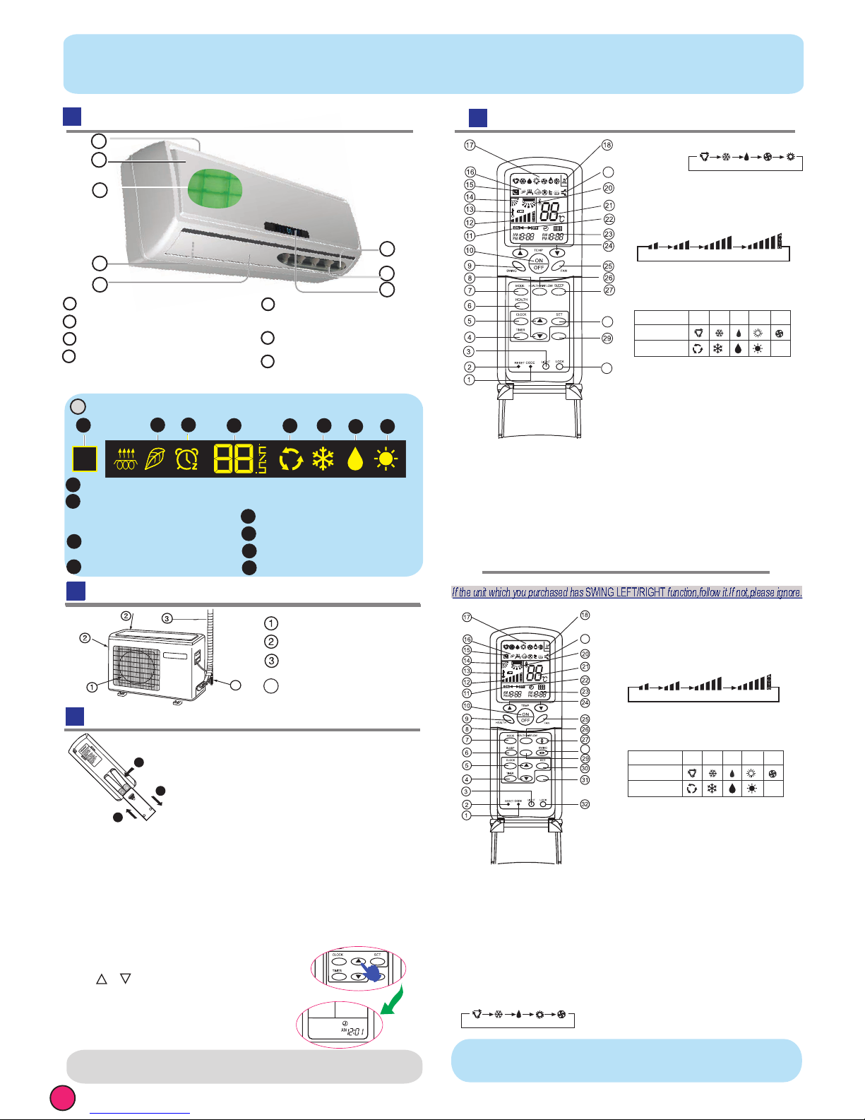
Outdoor Unit
Parts and Functions
Indoor Unit
Remote controller
If the unit which you purchased has healthy function,follow it.If not,please ignore.
NOTE:
Cooling only unit do not have displays and functions related with heating
Used to select CODE A or B with a press,
A or B will be displayed on LCD.
Please select A without special explanation.
1.CODE
When the remote controller appears abnormal,
use a sharp pointed article to press this button
to reset the remote controller normal.
2.RESET
Used to select TIMER ON, TIMER OFF,TIMER ON-OFF.
4. TIMER button
Used to set correct time.
5. CLOCK button
Used to select sleep mode.
6. SLEEP button
7. MODE button
AUTO COOL DRY
FAN
HEAT
Used to set clock and timer setting.
8. HOUR button
Used for unit start and stop.
10. ON/OFF button
11. TIMER ON display
12. FAN SPEED display
LOW HI
MED AUTO
13. LOCK display
14. SWING UP/DOWN display
15. SLEEP display
16. HEALTH display
Used to select your desired temperature.
17. Operation mode display
19.POWER/SOFT display
20. Left/right air flow display
Remote controller: to display theTEMP. setting.
21. TEMP display
22. TIMER OFF display
23. CLOCK display
24. TEMP button
Used to select fan speed: LOW,MED, HI, AUTO.
25. FAN button
Used to set the health airflow mode.
26. HEALTH AIRFLOW button
27. SWING UP/DOWN button
Used to select up or down air sending direction.
28. SWING LEFT/RIGHT button
Used to select left/right air flow.
30
Used to confirm timer and clock settings.
31.
SET button
Used to lock buttons and LCD display. If pressed, the
other buttons will be disabled and the lock condition
display appears. Press it once again, lock will be
canceled and lock condition display disappears.
LOCK
18.Signal sendin g display
3.LIGHT button
Control the lightening and extinguishing of
the indoor LED display board.
14
OUTLET
INLET
CONNECTING PIPING
AND ELECTRICAL WIRING
DRAIN HOSE
1
2
3
4
Remove the battery cover;
Load the batteries as illustrated.2 R-03
batteries, resetting key (cylinder);
Be sure that the loading is in line with the" + "/"-";
Load the battery,then put on the cover again.
The distance between the signal transmission head and the
receiver hole should be within 7m without any obstacle as well.
When electronic-started type fluorescent lamp or change-over
distance to the indoor unit should be shorter.
wireless telephone is installed in the type fluorescent lamp or room,
the receiver is apt to be disturbed in receivingthe signals, so the
Note:
Full display or unclear display during operation indicates the
If the remote controller can't run normally during operation, please
Remove the batteries in case unit won't be in usage for a long period.
If there are any display
after taking-out, just need to press reset key
Hint:
Loading of the battery / Clock set
remove the batteries and reload several minutes later.
Press CLOCK button, "AM" or "PM" flashes.
Press or to set correct time.
will change quickly. After time setting is
stop flashing while clock starts working.
Each press will increase or decrease
1
2
3
POWER/SOFT
FRESH
28
19
Used to set healthy function.
9. HEALTH button
32.
POWER/SOFT button
Used to set power/soft function.
Operation mode
AUTO
FAN
COOL DRY
Remote controller
Display board
HEAT
6
5
2
1
4
3
Inlet grille
Inlet
Air Purifying Filter (inside)
Outlet
Horizontal flap
6
4
2
1
5
3
5
2
1
5
3
6
8
Actual inlet grille may vary from the one shown in the
manual according to the product purchased
(adjust up and down air flow
Don't adjust it manually)
(adjust left and right air flow)
Vertical blade
4
Display board
8
4
2
3
1
6
5
7 8
(inside)
Anion generator
7
7
4
batteries have been used up.Please change batteries.
AUTO COOL DRY FAN HEAT
19
28
30
9.
SWING button
Used for unit start and stop.
10
. ON/OFF button
11. TIMER ON display
12. FAN SPEED display
LOW HI
MED AUTO
13. LOCK display
14. SWING UP/DOWN display
15. SLEEP display
16. HEALTH display
Used to select your desired temperature.
17. Operation mode display
19. POWER/SOFT display
20. Left/right air flow display
Remote controller: to display the TEMP. setting.
21. TEMP display
22. TIMER OFF display
23. CLOCK display
24. TEMP button
Used to select fan speed: LOW,MED, HI, AUTO.
25. FAN button
Used to set the health airflow mode.
26. HEALTH AIRFLOW button
27. SLEEP button
Used to select up or down air sending direction.
Used to confirm timer and clock settings.
28. SET button
29. POWER/SOFT button
Use to set power/soft function.
Used to select CODE A or B with a press,A or B
will be displayed on LCD.
Please select A without special explanation.
1.CODE
When the remote controller appears abnormal,
use a sharp pointed article to press this button
to reset the remote controller normal.
2.RESET
Used to select TIMER ON, TIMER OFF,
TIMER ON-OFF.
4. TIMER button
Used to set correct time.
5. CLOCK button
6. HEALTH button
7. MODE button
Used to set clock and timer setting.
8. HOUR button
Used to lock buttons and LCD display. If pressed, the
other buttons will be disabled and the lock condition
display appears. Press it once again, lock will be
cancelled and lock condition display disappears.
30. LOCK
Used to set healthy operation.
Used to select sleep mode.
POWER/SOFT
18.Signal sending display
3.LIGHT button
Control the lightening and extinguishing of
the indoor LED display board.
Operation mode
AUTO
FAN
COOL DRY
Remote controller
Display board
HEAT
If the unit which you purchased has
SWING LEFT/RIGHT
function,follow it.If not,please ignore.
Signal receiver hole
COOL display
HEAT display
HEALTH display
Dry display
4
2
3
1
6
7
5
(If the unit which you purchased
has healthy function,follow it.
TIMER OFF display
TIMER ON display,SLEEP display
If not,please ignore.)
Ambient temp.display
(When receiving the remote control signal,
display the set temperature and in the rest
this room temperature is only for reference.)
time the room temperature is displayed and
AUTO display
8
Clock set
1min. If the button is kept pressed,time
confirmed,press SET,"AM "and "PM"
29
FRESH
button
Use to set fresh air function.
(This function is unavailable on this models.)
2
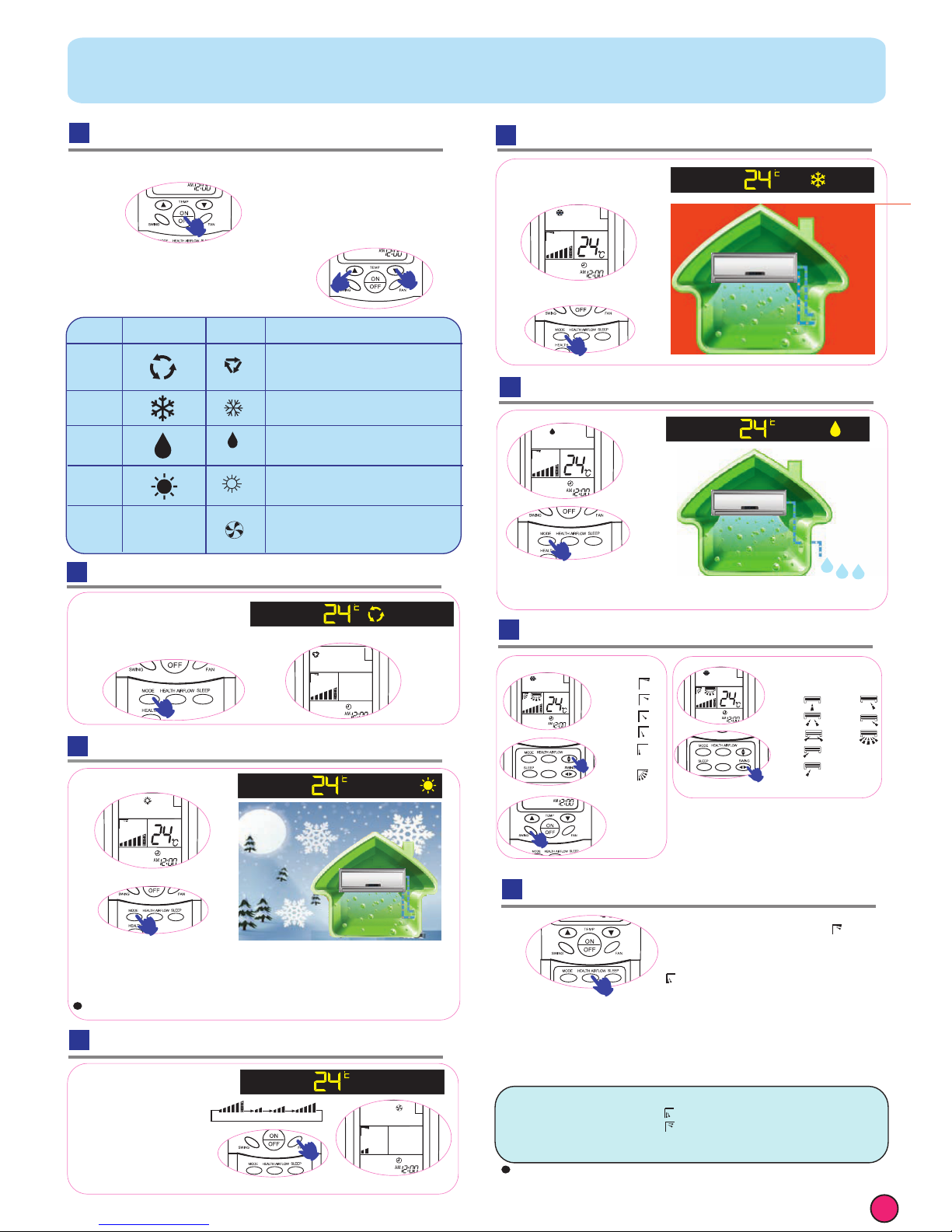
Operation
Unit start / stop
Note:
In DRY mode,when room temperature becomes lower than temp.setting
+2 C, unit will run intermittently at LOW speed regardless of FAN setting.
In HEAT mode,warm air will blow out after a short periodof the time
When FAN is set to AUTO, the air conditioner automatically adjusts
next time,just press ON/OFF button and unit will run in previous status.
Remote controller can memorize each operation status. When starting it
Cooling only unit do not have displays and functions related with heating
Press ON/OFF button, unit starts or stops.
According to the automatic
choice system in temperature
in indoors cold or make the
automatically adjusts
1.
2.In FAN operation mode
Auto Operation
Cool Operation
Heat Operation
Dry Operation
Fan Operation
When FAN is set to AUTO,
the air conditioner
the fan speed according
to room temperature.
the unit will not operate
in COOL mode but only
in FAN mode ,AUTO is not available in FAN mode.And temp.setting is disabled.
due to cold-draft prevention function.
the fan speed according to room temperature.
Note:
Air Flow Direction Adjustm
Select temp.setting
hot movement.
Health airflow Operation
The setting of health airflow function
1).Press the button of health airflow, appears
on the display. Avoid the strong airflow blows
2).Press the button of health airflow again,
appears on the display. Avoid the strong
Note:
1 .After setting the health airflow function, the position of inlet and outlet grills is fixed.
2.In heating, it is better to select the mode.
3.In cooling, it is better to select the mode.
4.In cooling and dry, using the air conditioner for a long time under the high air humidity,
a phenomenon falling drips of water occurs at the outlet grille .
5.Select the appropriate fan direction according to the actual conditions.
direct to the body.
strong airflow blows direct to the body.
3.The cancel of the health airflow function
Press the button of health airflow again, both the inlet and outlet grills of the
air conditioner are opened, and the unit goes on working under the condition
before the setting of health airflow function.
After stopping, the outlet grille will close automatically.
Notice: Cannot pull direct the outlet grille by hand. Otherwise,the grille will run
incorrectly. If the grille is not run correctly,stop for a minute and then start,
adjusting by remote controller.
0
Display Board
Remote
Controller
Note
COOL
DRY
HEAT
FAN
nothing
In DRY mode, when room temperature becomes
lower than temp.setting+2
o
C,unit will run intermittently
at LOW speed regardless of FAN setting.
Under the mode of auto operation, air conditioner will
automatically select Cool or Heat operation according
to room temperature.
air conditioner
automatically adjusts the fan speed
temperature.
When FAN is set to AUTO, the
according to room
In FAN operation mode, the unit will not operate in
COOL or HEAT mode but only in FAN mode ,AUTO is
not available in FAN mode.And temp.setting is disabled.
In FAN mode,SLEEP operation is not available.
Operation
Mode
AUTO
AUTO LO MED HI
Vertical flap
Pos.1
Pos.2
Pos.3
Pos.4
Pos.5
Pos.6
(Auto
swing)
Horizontal louvers
Pos.1
Pos.2
Pos.3
Pos.4
Pos.5
Pos.6
Pos.7
Pos.8
(This function is unavailable
on some models.)
FRESH
FRESH
 Loading...