

Haier AL24LP2VHA, AL36LP2VHA, AL48LP2VHA, AM24LP2VHA, AM36LP2VHA Installation Guide
...
Ductless Split Heat Pump
Installation Manual
Indoor
AM24LP2VHA
AM36LP2VHA
AM48LP2VHA
AL24LP2VHA
AL36LP2VHA
AL48LP2VHA
AW24LP2VHA
AW36LP2VHA
Outdoor
1U24LP2VHA
1U36LP2VHA
1U48LP2VHA
Nomenclature
T
able of Cont
............................................................................................................................... 2
ents
................................................................................................................... 3
ety ........................................................................................................................................... 4
Saf
Section A - Outdoor Unit Installation ............................................................................................ 7
Section B - Indoor Unit Installation - Wall Mount ......................................................................... 13
Section C - Indoor Unit Installation - Cassette ............................................................................. 17
Section D - Indoor Unit Installation - High ESP Duct ................................................................... 23
Section E - Wir
ed Controller YR-E17 ............................................................................................ 29
Section F - Wireless Remote Controller ....................................................................................... 37
ENGLISH
1 U 24 LP 2 V H A
1 U 18 ES 2 V H A
Unit Type
A = Indoor Unit
1 = Single Zone Outdoor
2 = Two Zone Outdoor
3 = Three Zone Outdoor
4 = Four Zone Outdoor
Nomenclature
Nomenclature
Product Revision
Unit Type
U = Outdoor
B = Casse e Type Indoor
D = High ESP Duct Type Indoor
M=High Static Duct Type Indoor
W = Wall Mount Type Indoor
L = Large Cassette Type Indoor
Nominal Capacity
In Btu/hr (x 1000)
Product Family
- LP:LP=FlexFit Pro Series
System Type
H = Heat Pump
C = Cool Only
Compressor Speed
V = Variable Speed
Voltage
1 = 115V
2 = 230V
PAGE 2
INTRODUCTION
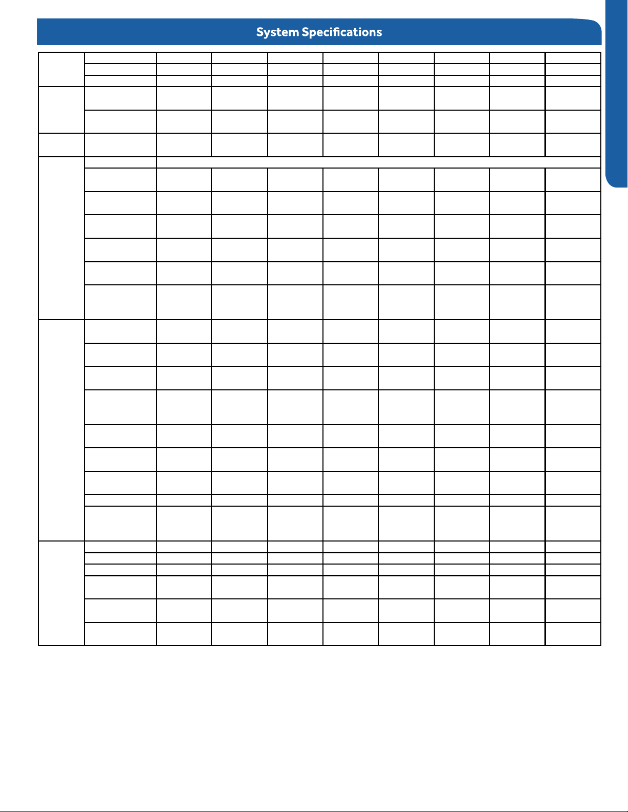
Model
Name
Operating
Range
Power
Supply
Outdoor
Unit
Indoor Unit
Refrigerant
Line
System AW24LP AW36LP AM24LP AM36LP AM48LP AL24LP AL36LP AL48LP
Outdoor
Indoor AW24LP2VH AW36LP2VH AM24LP2VH AM36LP2VH AM48LP2VH AL24LP2VH AL36LP2VH AL48LP2VH
Cooling
Heating
Voltage, Cycle,
Maximum Fuse
Minimum Circuit
Height
Width
Depth
(Ship/Net)-
°F(°C)
°F(°C)
Phase
V/Hz/-
Compressor
Size
A
Amp
A
Dimension:
in (mm)
Dimension:
in (mm)
Dimension:
in (mm)
Weight
(kg)
Dimension:
Height
in (mm)
Dimension:
Width
in (mm)
Dimension:
Depth
in (mm)
Max. External
Static Pressure
1U24LP2VH 1U36LP2VH 1U24LP2VH 1U36LP2VH 1U48LP2VH 1U24LP2VH 1U36LP2VH 1U48LP2VH
0~115
(-18~46)
-4~75
(-20~24)
208-
230/60/7
25.0 30 25.0 30 40 25.0 30 40
21.0 26.0 21.0 26.0 35.0 21.0 26.0 35.0
38 (965) 38 (965) 38 (965) 38 (965) 53 1/8 (1350) 38 (965) 38 (965) 53 1/8 (1350)
37 3/8(950) 37 3/8(950) 37 3/8(950) 37 3/8(950) 37 3/8(950) 37 3/8(950) 37 3/8(950) 37 3/8(950)
14 5/8(370) 14 5/8(370) 14 5/8(370) 14 5/8(370) 14 5/8(370) 14 5/8(370) 14 5/8(370) 14 5/8(370)
202.8/ 176.4
lbs
(92/80)
13 1/4(336) 14 3/8(365) 9 7/8 (250) 9 7/8 (250) 9 7/8 (250) 9 5/8 (246) 9 5/8 (246) 11 3/8 (288)
43 7/8(1115)
9 9/16(243) 10 7/8(275) 25 3/4 (655) 28 3/8 (720) 28 3/8 (720) 33 1/8(840) 33 1/8(840) 33 1/8(840)
NA NA 0.6(150) 0.6(150) 0.6(150) NA NA NA
0~115
(-18~46)
-4~75
(-20~24)
208-
230/60/10
207.2/180.7
(94/82)
51
13/16(1316)
0~115
(-18~46)
-4~75
(-20~24)
208-
230/60/8
202.8/ 176.4
(92/80)
37 5/8 (957) 59 (1500) 59 (1500) 33 1/8(840) 33 1/8(840) 33 1/8(840)
0~115
(-18~46)
-4~75
(-20~24)
208-
230/60/11
DC Inverter Driven Rotary
207.2/180.7
(94/82)
0~115
(-18~46)
-4~75
(-20~24)
208-
230/60/13
260.1/231.5
(118/105)
0~115
(-18~46)
-4~75
(-20~24)
208-
230/60/9
202.8/ 176.4
(92/80)
0~115
(-18~46)
-4~75
(-20~24)
208-
230/60/12
207.2/180.7
(94/82)
(-18~46)
(-20~24)
230/60/14
260.1/231.5
(118/105)
in.W.G(Pa)
Drainpipe Size
in
O.D.
Internal
Condensate
Max. Drain-Lift
height
in(mm)
Grill Model NA NA NA NA NA PB-950KB PB-950KB PB-950KB
Weight
(Ship/Net)-
lbs
(kg)
Connections Flare Flare Flare Flare Flare Flare Flare Flare
Liquid O.D.
Suction O.D.
Factory Charge
in
in
Oz
Maximum Line
Length
Ft / m
Maximum Height
Ft / m
NA NA 1 1/4 1 1/4 1 1/4 1 1 1
NA NA Standard Standard Standard Standard Standard Standard
NA NA 27 9/16(700) 27 9/16(700) 27 9/16(700) 39 3/8 (1000) 39 3/8 (1000) 39 3/8 (1000)
45.4/37.5(20.
6/17)
3/8 3/8 3/8 3/8 3/8 3/8 3/8 3/8
5/8 5/8 5/8 5/8 5/8 5/8 5/8 5/8
88.2 88.2 88.2 88.2 131 88.2 88.2 131
165 (50) 165 (50) 165/50 165/50 230/75 165/50 165/50 230/75
100/30 100/30 100/30 100/30 100/30 100/30 100/30 100/30
55.1/46.3(25.
5/21)
81.1/68.8
(36.8/31.2)
130.1/121.3
(59/55)
132.3/114.6
(60/52)
79.4/68.3
(36/31)
79.4/68.3
(36/31)
83.8/70.5
ENGLISH
0~115
-4~75
208-
(38/32)
INTRODUCTION
PAGE 3
SAFETY OVERVIEW
Read These Safety Precautions
Be sure to read the safety precautions before conducting work. The items are classified into “Warning” and “Caution.” The
“Warning" items are especially important since they can lead to death or serious injury if not followed closely. Under certain
conditions, the "Caution" items can also lead to accident or injury if they are not followed. Therefore, be sure to observe all
ENGLISH
safety precautions listed here.
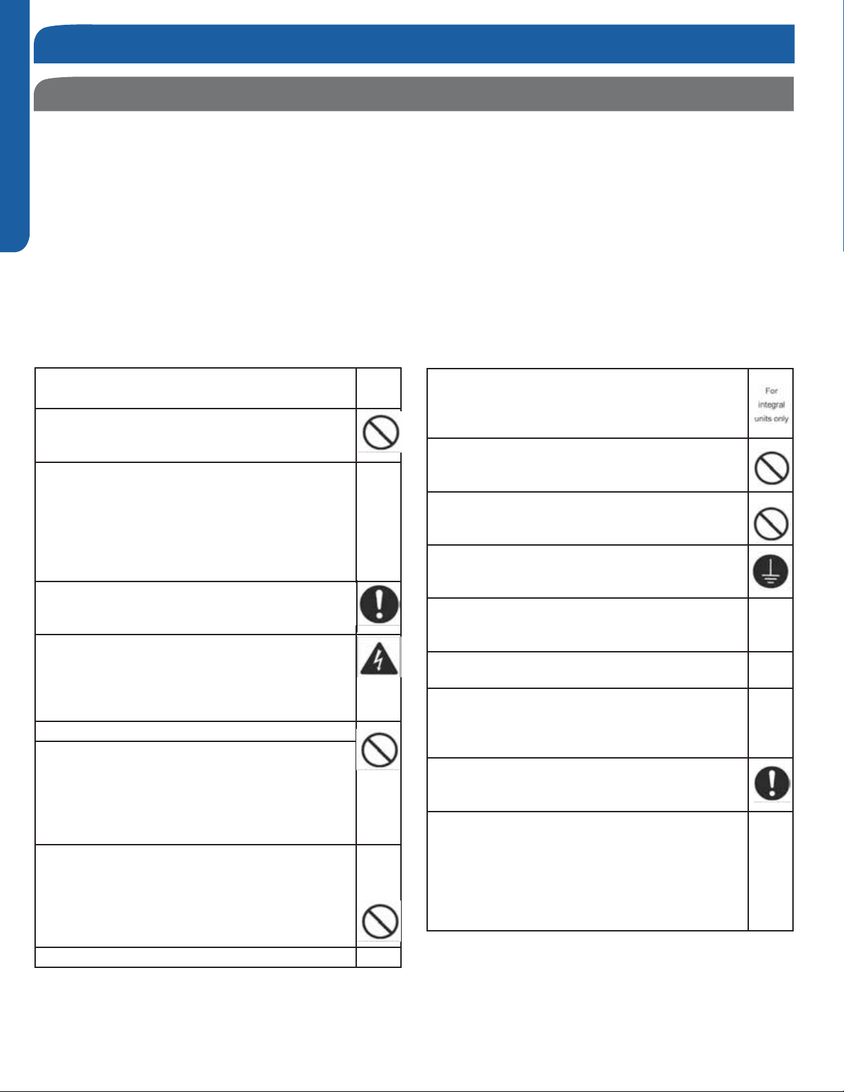
∆ This symbol means be careful when doing this procedure or touching this equipment.
ᴏ This symbol indicates a prohibited action.
• This symbol means that an action must be taken; the action will be listed next to the symbol.
After the repair work is complete, be sure to conduct a test operation to ensure that the equipment operates properly;
explain the safety precautions for operating the equipment to the customer.
Warning
Disconnect the power cable from electrical supply
before disassembling equipment for repair.
If the refrigerant discharges during the repair work,
DO NOT touch the discharging refrigerant. The
refrigerant can cause frostbite.
Before disconnecting the suction or discharge
pipe of the compressor at the brazed connections,
recover the refrigerant in a well-ventilated area. If
refrigerant remains inside the compressor, the
refrigerant or the refrigerating machine oil will
discharge when the pipe is disconnected and may
cause injury.
If the refrigerant leaks during the repair work,
ventilate the area. The refrigerant can generate
toxic gases when it contacts ames.
The step-up capacitor supplies high-voltage
electricity to the electrical components of the
outdoor unit. Be sure to discharge the capacitor
completely before conducting repair work. A
charged capacitor can cause electrical shock.
Be sure to use parts listed in the service parts
of the applicable model and appropriate tools to
conduct repair work. Never attempt to modify
the equipment. The use of inappropriate parts or
tools can cause electrical shock, excessive heat
generation, or re.
When relocating the equipment make sure that
the new installation site has sufficient strength to
withstand the weight of the equipment. If the new
installation site does not have sucient strength
and if the installation work is no
securely, the equipment can fall and cause injury.
t conducted
Be sure to install the product correctly by using the
standard installation frame provided. Incorrect use
of the installation frame and improper installation
can cause equipment to fall, resulting in injury.
Do not repair the electrical components with wet
hands. Working on equipment with wet hands can
cause electrical shock.
Do not clean the equipment by splashing water.
Washing the unit with water can cause an electrical
shock.
Make sure that the unit is grounded when reparing
the equipment in a wet or humid place to avoid
electrical shocks.
Be sure to turn o the power switch when cleaning
the equipment; the internal fan rotates at a high
speed and may cause injury.
Do not tilt the unit when removing it. Water inside
the unit can spill, wetting the oor.
Be sure to check that the refrigeration cycle section
has cooled down suciently before conducting
repair work. Working on the unit when the
refrigerating cycle is hot can cause burns.
Use the brazing equipment in a well-ventilated
place. Using the brazing equipment in an enclosed
room can cause oxygen deficiency.
Be sure to use a dedicated power circuit for the
equipment; follow appropriate technical standards
for the electrical equipment, the internal wiring
regulations, and the instruction manual for
installation when conducting electrical work.
Insucient power circuit capacity and improper
electrical work can cause an electrical shock or re.
PAGE 4
INTRODUCTION
SAFETY OVERVIEW
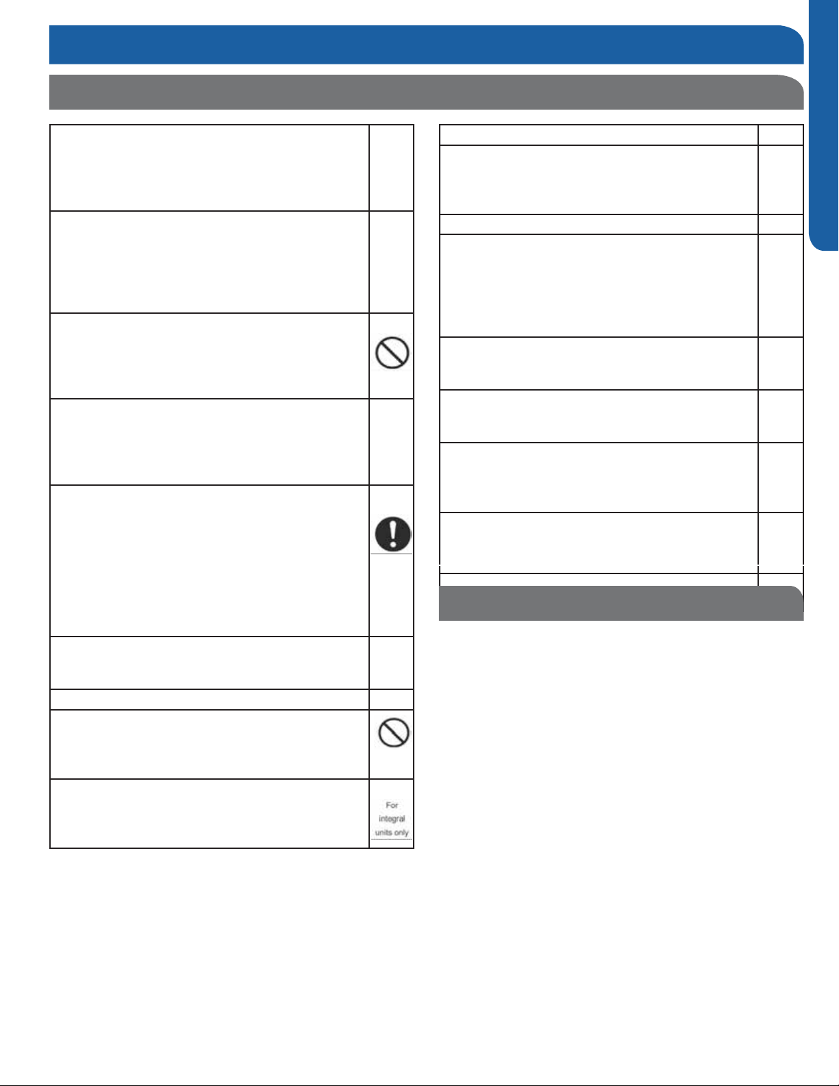
Read These Safety Precautions
Be sure to use the specied cable to connect
between the indoor and outdoor units. Make the
connections securely and route the cable properly
so that there is no force pulling the cable at the
connection terminals.
When connecting the cable between the indoor and
outdoor units make sure that the terminal cover
does not lift o or dismount because of the cable.
If the cover is not mounted properly, the terminal
connection section can cause an electrical shock,
excessive heat generation, or re.
Do not damage or modify the power cable.
Damaged or modied power cables can cause
electrical shock or re. Placing heavy items on the
power cable and heating or pulling the power cable
can damage the cable.
Do not introduce air into the refrigerant system. If
air enters the refrigerant system, an excessively
high pressure results, causing equipment damage
and injury.
If the refrigerant leaks, be sure to locate the leak
and repair it before charging the system with
additional refrigerant. If the leak cannot be located
and the repair work cannot be stopped, be sure to
perform pump-down and close the service valve to
prevent the refrigerant from leaking into the room.
The refrigerant itself is harmless, but it can
generate toxic gases when it contacts a heat
source such as another appliance or an open flame.
When replacing the remote control battery, be
sure to safely dispose of the battery.
Do not install the equipment in a place where
there is a possibility of combustable gas leaks. If
combustible gas leaks and remains near the unit, it
may cause a re.
Be sure to install the packing and seal on the
installation frame correctly. If the packing and
seal are not properly installed, water can spill out,
wetting furniture and the oor.
ENGLISH
Replace power cables and lead wires if they are
scratched or deteriorated. Damaged cable and
wires can cause electrical shock, excessive heat
generation, or re.
Check to see if the parts are mounted correctly,
that the wires are connected correctly, and that
connections at soldered or crimped terminals are
secure. Improper installation and connections can
cause excessive heat generation, electrical shock,
and re.
If the installation platform or frame has deteriorated
or corroded, replace it. Corroded platform or frames
can cause the unit to fall, resulting in injury.
Check to make sure that the equipment is grounded.
Repair it if it is not properly grounded. Improper
grounding can cause an electrical shock.
Be sure to measure the installation resistance of
the repair. Be sure that the resistance is 1 M ohm
or higher. Faulty installation can cause an electric
shock.
Be sure to check the drainage of the indoor unit after
the repair. Faulty drainage can cause a water leak
from indoor unit and could cause property damage.
Important Safety Related
Installation Information
Indoor Clearances: If noncompliant may lead to temperature
control complaints.
Wire Sizing: If noncompliant may lead to communication errors
and inverter irregular operation.
Splices in Field Wiring: Splices between the wires that connect
between the outdoor and indoor unit should be avoided.
Sealing Penetrations: If penetrations at back of unit are not
sealed, unconditioned air may be drawn into the back of the
indoor wall mount unit. Temperature control and capacity
complaints may occur.
INTRODUCTION
PAGE 5

[This page intentionally left blank.]
Section A - Outdoor Unit Installation
Step 1 - Installation of the Outdoor Unit
Attaching Drain Elbow to Outdoor Unit
(Heat Pump models only)
1.1
Step - 1.1
If attaching the supplied drain elbow to the outdoor unit,
do so prior to attaching the refrigerant lines and wiring.
Extension piping to attach to this tting is eld supplied.
Electrical Connections for the Outdoor Unit
1.2
Step - 1.2
Remove the cover plate of the outdoor unit to expose the
terminal block connections.
1.3
Step - 1.3
Connect the wiring for both the power source and indoor
wiring.
Wire the system according to applicable national / local
codes.
Verify that the wiring connections for the indoor unit match
wire for wire.
(1-1, 2-2, 3-3, Gnd-Gnd). Failure to wire the system correctly
may lead to improper operation or component damage.
Step 1.1
Step 1.3
ENGLISH SECTION A
Step1.2
Step 1.4
1.4
Step - 1.4
Replace the cover plate.
Step 2 - Connecting the Indoor Unit
*See indoor section A, B, or C for electrical connections.
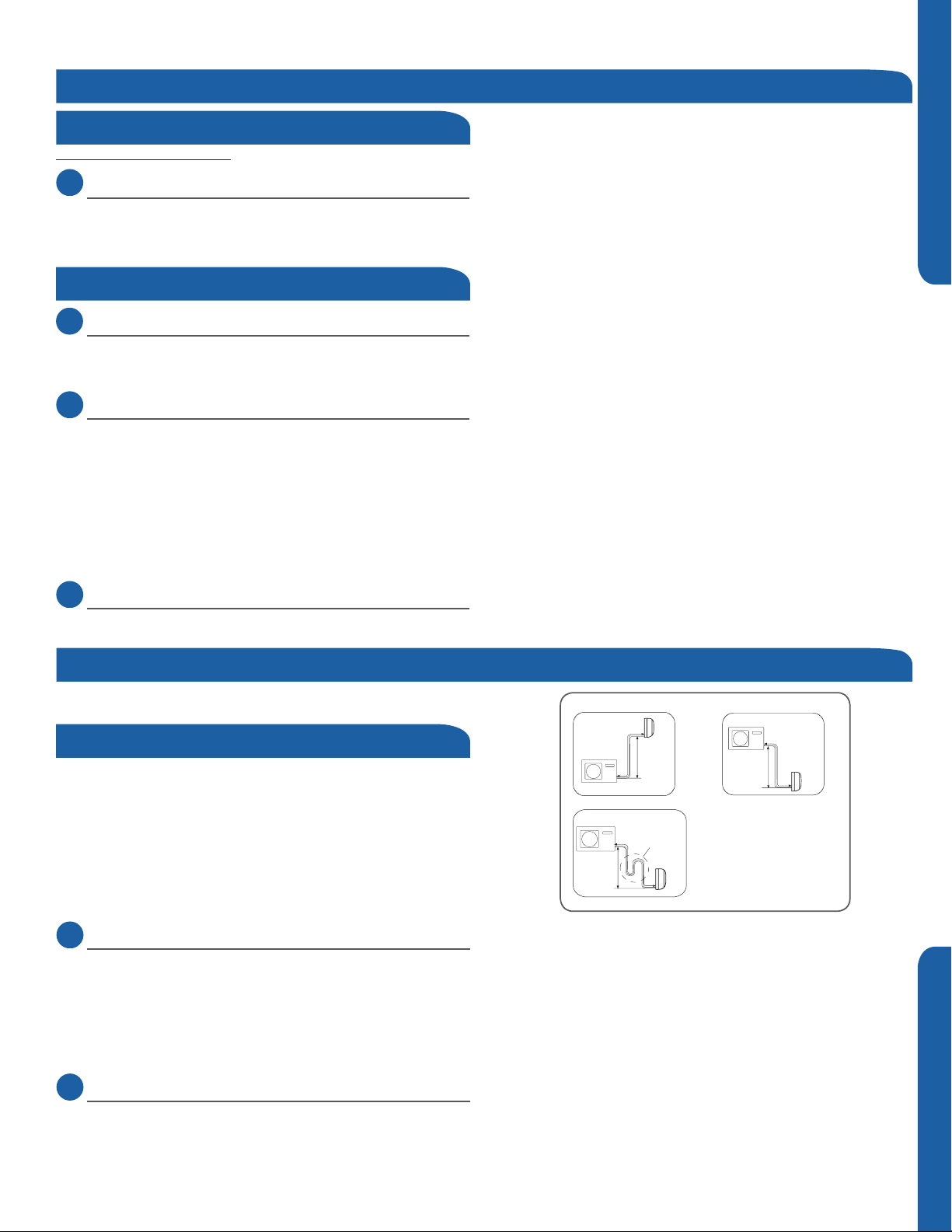
Piping
The standard lineset length is 25ft. If the installation length is
different, adjust the refrigerant charge by 0.5oz/ft.for the
24k,36k,42k and 48k model. (Illustration 4)
Cut the lineset to length, are and attach the piping to the
outdoor unit valves.
Torque the ttings to the specications shown in the torque
chart.
2.1
Step - 2.1
Refrigerant piping connections at the indoor unit are made
utilizing flare joints. Follow standard practices for creating
pipe flares. When cutting and reaming the tubing, use caution
to prevent dirt or debris from entering the tubing. Remember
to place the nut on the pipe before creating the flare.
CAUTION
Outdoor unit
Outdoor unit
Outdoor unit
Indoor unit
B
A
Max. Elevation: A Max.
●
= 100ft / 30m (24k / 36k)
In case the height of A is more than
●
Oil trap
B
Indoor unit
A
15ft / 5m, an oil trap should be
installed every 16-23ft /5-7m
●
Max. Length: B Max
= 165ft / 50m (24k / 36k)
B
Indoor unit
A
Illustration 4
2.2
Step - 2.2
To join the lineset piping together, directly align the piping
are to the tting on the other pipe, then slide the nut onto
the tting and tighten. Misalignment may result in a leaking
connection.
INSTALLATION
Step 2.2Step 2.1
PAGE 7
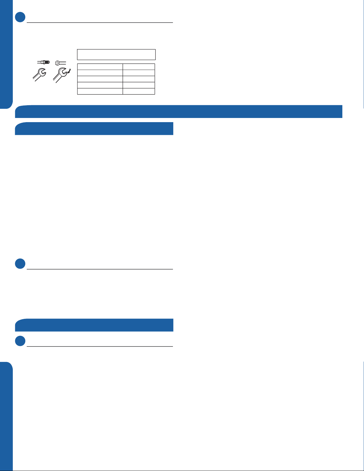
2.3
Step - 2.3
Two wrenches are required to join the are connections, one
standard wrench, and one torque wrench. See Table 1 for the
specic torque per piping diameter.
Forced fasteningwithout carefulcentering may
damagethe threads and cause a leakageofgas.
Pipe Diameter(ǿ)Fastening torque
Liquid side6.35mm(1/4") 18N.m/13.3Ft.lbs
Liquid/Gas side9.52mm(3/8") 42 N.m/30.1Ft.lbs
Gasside12.7mm(1/2") 55N.m/40.6Ft.lbs
Gasside15.88mm(5/8") 60 N.m/44.3Ft.lbs
ENGLISHSECTION A
Half union
Spanner
Flarenut
Torque wrench
Table 1
Step 3 - Leak Test and Evacuation
Leak Test
Hazard of Explosion! Never use an open flame to detect
refrigerant leaks.. Explosive conditions may occur. Use a leak
test solution or other approved methods for leak testing.
Failure to follow recommended safe leak test procedures
could result In death or serious injury or equipment or
property damage.
Use only dry nitrogen with a pressure regulator for
pressurizing unit. Do not use acetylene, oxygen or
compressed air or mixtures containing them for pressure
testing. Do not use mixtures of a hydrogen containing
refrigerant and air above atmospheric pressure for pressure
testing as they may become flammable and could result in
an explosion. Refrigerant used as a trace gas should only be
mixed with dry nitrogen for pressurizing units. Failure to
follow these recommendations could result in death or
serious injury or equipment or property damage.
Step 2.3
Step 3.1 Step 3.2
3.1
Step - 3.1
Using a tank of nitrogen with attached regulator, charge the
system with 150 PSIG of dry nitrogen. Use adapter AD-87
(field supplied) to connect to the service valve. Check for
leaks at the flare fittings using soap bubbles or other
detection methods. If a leak is detected, repair and recheck.
If no leaks are detected, proceed to evacuate the system.
System Evacuation
3.2
Step - 3.2
Attach a manifold gauge, micron gauge, and vacuum pump
to the suction line port using adapter AD-87 (eld supplied).
(Illustration 5)
Evacuate the system to 350 microns.
Close the vacuum pump valve and check the micron
gauge. If the gauge rises above 500 microns in 60 seconds,
evacuation is incomplete or there is a leak in the system. If
the gauge does not rise above 500 microns in 60 seconds,
evacuation is complete.
Illustration 5
PAGE 8
INSTALLATION
3.3
Step - 3.3
Remove the adapter and hose connection from the
suction line port, and replace the cap. Hoses should not be
removed and service valves should not be opened until any
additional refrigerant needed for a refrigerant line longer
than 25 ft. has first been added.
3.4
Step - 3.4A & 3.4B
Remove the cap from the liquid line valve. Using the hex
wrench, open the valve, then replace and tighten the cap.
3.5
Step - 3.5A & 3.5B
Remove the cap from the suction line valve. Using the hex
wrench, open the valve, then replace and tighten the cap.
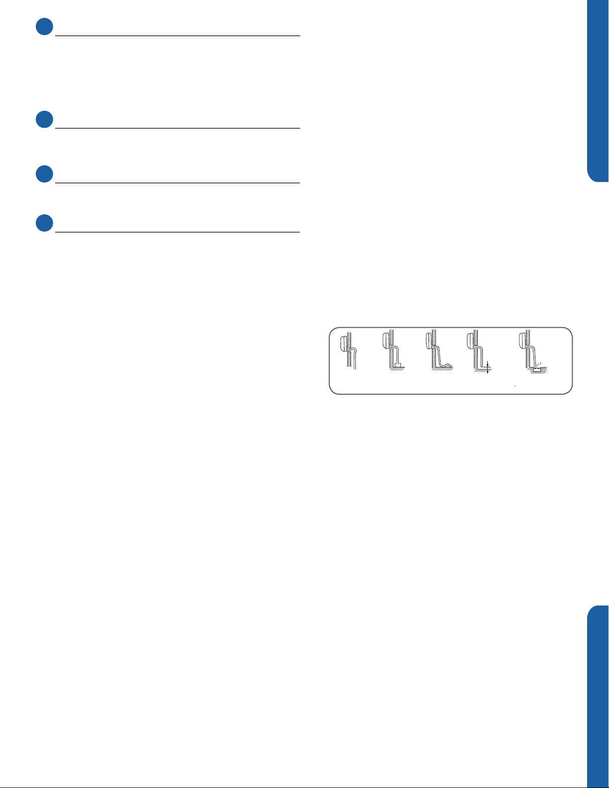
3.6
Step - 3.6
Wrap the lineset, drain line, and wiring starting at the bottom
of the bundle with an overlap type wrap, concluding at the
piping hole. Use a sealant to seal the piping hole opening
to prevent weather elements from entering the building.
(Illustration 6)
Step 3.3 Step 3.4A
Step 3.4B
Step 3.5A
ENGLISH SECTION A
Verify the condensate drain line has a constant pitch
downward for proper water ow. There should be no kinks
or rises in the tubing which may cause a trapping eect
resulting in the failure of the condensate to exit the piping.
Step 3.5B
It becomes
high midway.
Theendis immersed in water.
It waves.
Thegap with the
ground is too small
Illustration 6
Step 3.6
Lessthan
5cm
Thereisthe bad
smellfrom a sewer
INSTALLATION
PAGE 9
Step 4 - Charging
See Steps 5.2 - 5.5 for evacuating the system prior to
charging. The standard lineset length is 25ft. If the
installation length is different, adjust the refrigerant charge
by .5 oz / ft. for the 24K, 36K and 48K model. (Step 4 Illustration 4)
ENGLISHSECTION A
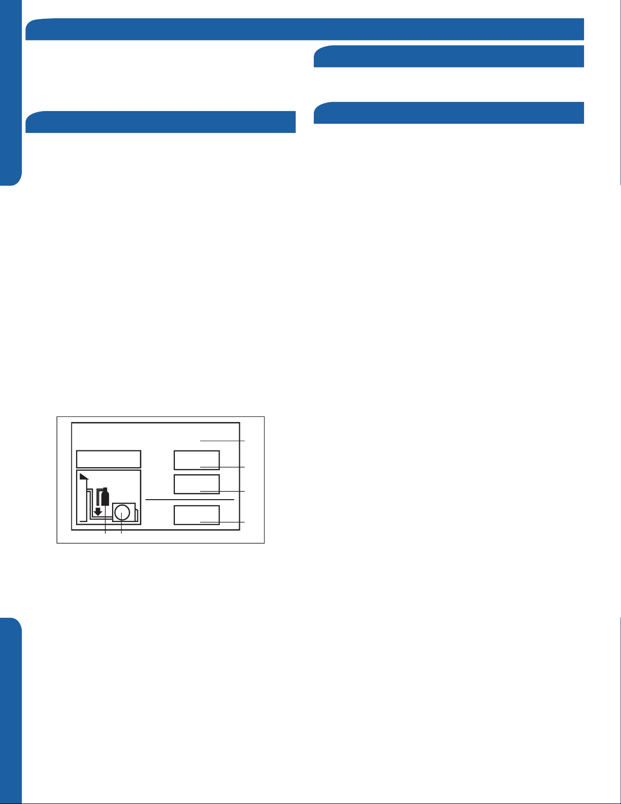
This product contains uorinated greenhouse gases covered
by the Kyoto Protocol. Do not vent into the atmosphere.
Refrigerant type: R410A
GWP* value: 1975
GWP = global warming potential
Please ll in with indelible ink,
• 1 the factory refrigerant charge of the product
• 2 the additional refrigerant amount charged in the eld and
• 1+2 the total refrigerant charge on the refrigerant charge
label supplied with the product.
The lled out label must be adhered in the proximity of the
product charging port (e.g. onto the inside of the stop valve
cover).
A - contains uorinated greenhouse gases covered by the
Kyoto Protocol
B - factory refrigerant charge of the product: see unit name
plate
C - additional refrigerant amount charged in the eld
D - total refrigerant charge
E - outdoor unit
F - refrigerant cylinder and manifold for charging
Refrigerant Charge Label
System Test
Using the instruction manual, show the customer how to
properly use and care for the equipment.
Check Items for Test Run
Put check mark √ in boxes
No refrigerant leaks from line sets or other connections?
Are the linesets insulated properly?
Are the connecting wirings of indoor and outdoor firmly
inserted to the terminal block?
Is the connecting wiring of indoor and outdoor rmly
connected?
Is condensate draining correctly?
Is the indoor unit securely attached?
Is power source voltage correct according to local code?
Is there any noise?
Is the lamp normally lighting?
Are cooling and heating (when in heat pump) performing
normally?
Is the operation of room temperature sensor normal?
Contains fluorinated greenhouse gases
covered by the Kyoto Protocol
R410A
2
1=
2=
oz
oz
1
1+2=
FE
oz
A
B
C
D
PAGE 10
INSTALLATION
Section 5 - Explaining Operation to the End User
Protecti on wa lls
• Using the OPERATING INSTRUCTIONS, explain to the user how to use the air conditioner (the remote controller, removing
the air lters, placing or removing the remote controller from the remote controller holder, cleaning methods, precautions for
operation, etc.)
• Recommend that the user read the OPERATING INSTRUCTIONS carefully.
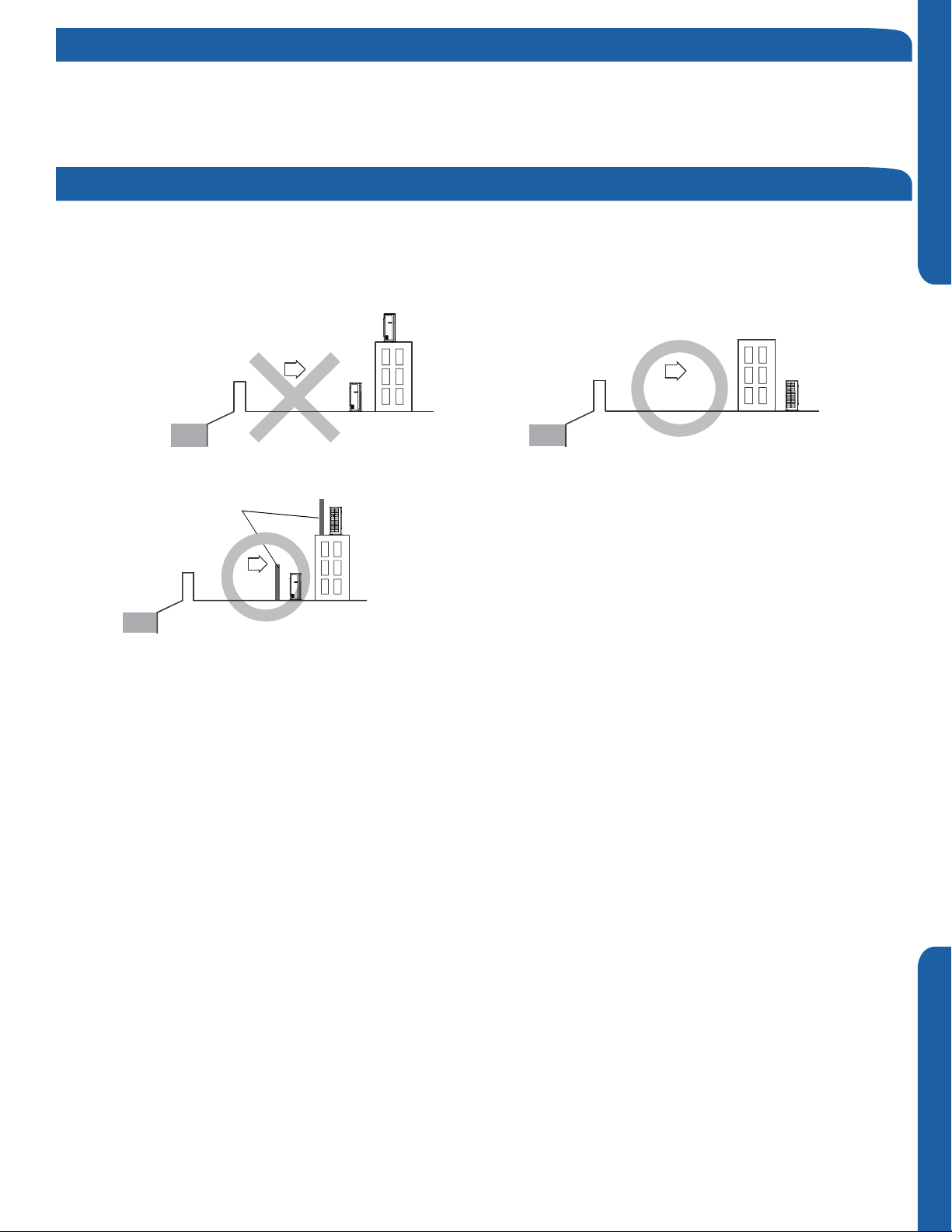
Section 6 - Seacoast Application
• The outdoor unit should be installed at least ½ mile away from the salt water, including seacoasts and inland waterways. If
the unit installed from ½ mile to 5 miles away from the salt water, including seacoasts and inland waterways, please follow the
installation instruction below.
• Install the outdoor unit in a place (such as near buildings etc.) where it can be protected from sea breeze which can damage
the outdoor unit.
ODU
ENGLISH SECTION A
Sea breeze
Sea
ODU
Sea breeze
ODU
Sea
• If you cannot avoid installing the outdoor unit by the seashore, construct a protection wall around it to block the sea breeze.
• A protection wall should be constructed with a solid material such as
concrete to block the sea breeze and the height and the width of the wall
ODU
should be 1.5 times larger than the size of the outdoor unit. Also, secure
over 28 in (700mm) between the protection wall and the outdoor unit for
Sea
Sea breeze
ODU
exhausted air to ventilate.
• Install the outdoor unit in a place where water can drain smoothly.
• If you cannot nd a place satisfying above conditions, please contact manufacturer. Make sure to clean the sea water and the
dust on the outdoor coil.
INSTALLATION
PAGE 11

[This page intentionally left blank.]
Section B - Indoor Unit Installation - Wall Mount
Required Tools for Installation
• Drill
• Wire Snipper
• Hole Saw 2 3/4”
• Vacuum pump
• Soap-and-water solution or gas leakage
detector
• Torque wrench
• 17mm, 22mm, 26mm
• Tubing cutter
• Flaring tool
• Razor knife
• Measuring tape
• Level
• Micron gauge
• Nitrogen
• Mini-Split AD-87 Adapter (1/4” to 5/16”)
• A - Non-adhesive Tape
• B - Adhesive Tape
• C - Saddle (L.S.) with screws
• D - Electrical wiring
• E - Drain hose (Included)
• F - Insulation
• G - Piping hole cover (Included)
Step 1 - Preparation
Procedure for Selecting the Location
• Choose a place solid enough to bear the
weight and vibration of the unit and where
the operation noise will not be amplied.
• Choose a location where the hot air
discharged from the unit or the operation
noise and will not cause a nuisance to the
user.
• There must be sucient space for
carrying the unit into and out of the site.
• There must be sucient space for air
passage and no obstructions around the
air inlet and air outlet.
• The site must be free from the possibility
of ammable gas leakage in a nearby
place.
• Install units, power cords and inter-unit
cables at least 10ft away from television
and radio sets. This is to prevent
interference to images and sounds.
(Noise may be heard even if they are more
than 10ft away depending on radio wave
conditions.)
ENGLISH SECTION B
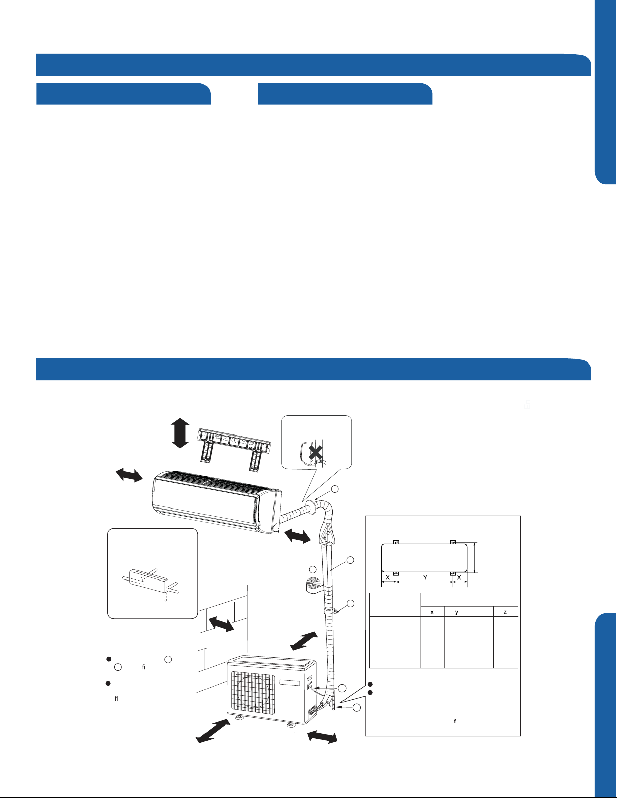
Clearances of Indoor and Outdoor Units
This picture is for reference only. Your product may look dierent. Read this manual before installation. Explain the operation of the unit to the user according to
this manual.
The models adopt HFC free refrigerant R410A
Attention must be paid to
more than 4in.
more than
4in.
Arrangement of piping
directions
Rear left
Left
Below
The marks from to
G
in the
name of the parts.
The distance between
the indoor unit and the
than 6 feet.
gure are the
oor should be more
Rear
right
Right
A
more than 4in.
the pitch of drain hose
more than 4in.
more than 4in.
G
Floor fixing dimensions of the outdoor unit
(Unit: inch)
eet t
23 5/8”
he l
Z
6 7/8”
ocal code.
16”
A
F
C
Fixing of outdoor unit
D
E
1 2
Model
1U24/36/42/48
LP2VHA
Anchor the outdoor unit to the pad.
When ins
he i
wall, t
Dimensions(inches)
1 x2
6 7/8”
talling the outdoor unit on a roof or a outside
hould m
nstallation s
more than 24in.
more than 6in.
INSTALLATION
PAGE 13
 Loading...