

Page 1

AMANA
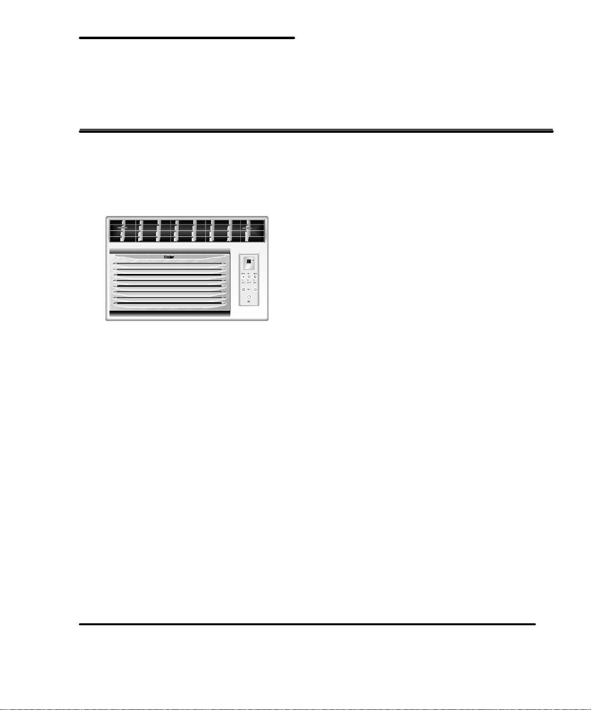
WINDOW TYPE
AIR CONDITIONER
Service Manual
Part # AC-8888-115
Page 2
Domestic Air Conditioner
SERVICE MANUAL
Models
ACB065R & ACB055E
l Features
l Top-Discharge Air Flow
l Ultra Quiet Operation
l Safty Power Cord
l EnvicoCleanTMCoil
l Easy-Access Washable Filter
l Digital Display&Timer
l Energy Star(ACB055E)
Page 3

Content
1、 Product Code Illumination And Series introduction ---------------------------- 2
2、 Features -----------------------------------------------------------------------------------------3
3、 Specifications -------------------------------------------------------------------------------- 4
4、 Safety and Precaution -----------------------------------------------------------------------5
5、Warning and Cautions ----------------------------------------------------------------------6
6、Net Dimention ---------------------------------------------------------------------------------7
7、Installation and Accessory Parts -------------------------------------------------------8
8、Parts and Functions -----------------------------------------------------------------------10
9、Abnormity Diagnose -------- ---------------------------------------------------------------13
10、System Flow Chart -----------------------------------------------------------------------14
11、Circuit Diagram ----------------------------------------------------------------------------15
12、Maintenance Service and Trouble Shooting -----------------------------------16
13、Wiring Diagram --------------------------------------------------------------------------18
14、Exploded View and Parts Lists -----------------------------------------------------19
1
Page 4
E: The type of power supply
X: 115V/50HZ
V:208/220V/50HZ
F: Function code
C-Cooling only
H-Heating pump
E-Electric aided heating
G: Design code
E SA
A B C D
A: Abbreviation of Energy Star
B: The type of power supply
3: 115V/50HZ
C: Nominal cooling capacity(BTU/h) with the first two numbers based on one
thousand unit
D: Design code
Examples:
ACB065R
It represents remote contrl window air conditioner.Cooling capacity is 6000BTU/h and
the power supply is 115V /60Hz.
ESA3055
It represents remote contrl window air conditioner.Cooling capacity is 6000BTU/h and
the power supply is 115V /60Hz.
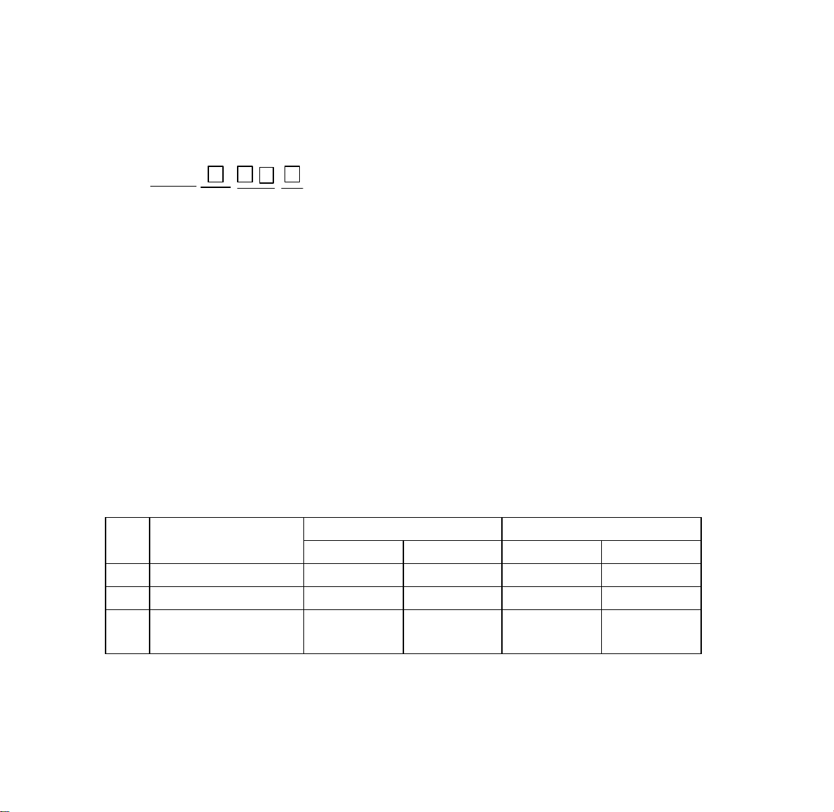
2.Standard situation/conditions
No. Operating condition
1 Nominal cooling 27 19 35 24
2 Nominal heating / / / /
Nominal electrical
3
heating
Indoor air state outdoor air state
D.B.℃ W.B.℃ D.B.℃ W.B.℃
/ / / /
2
Page 5
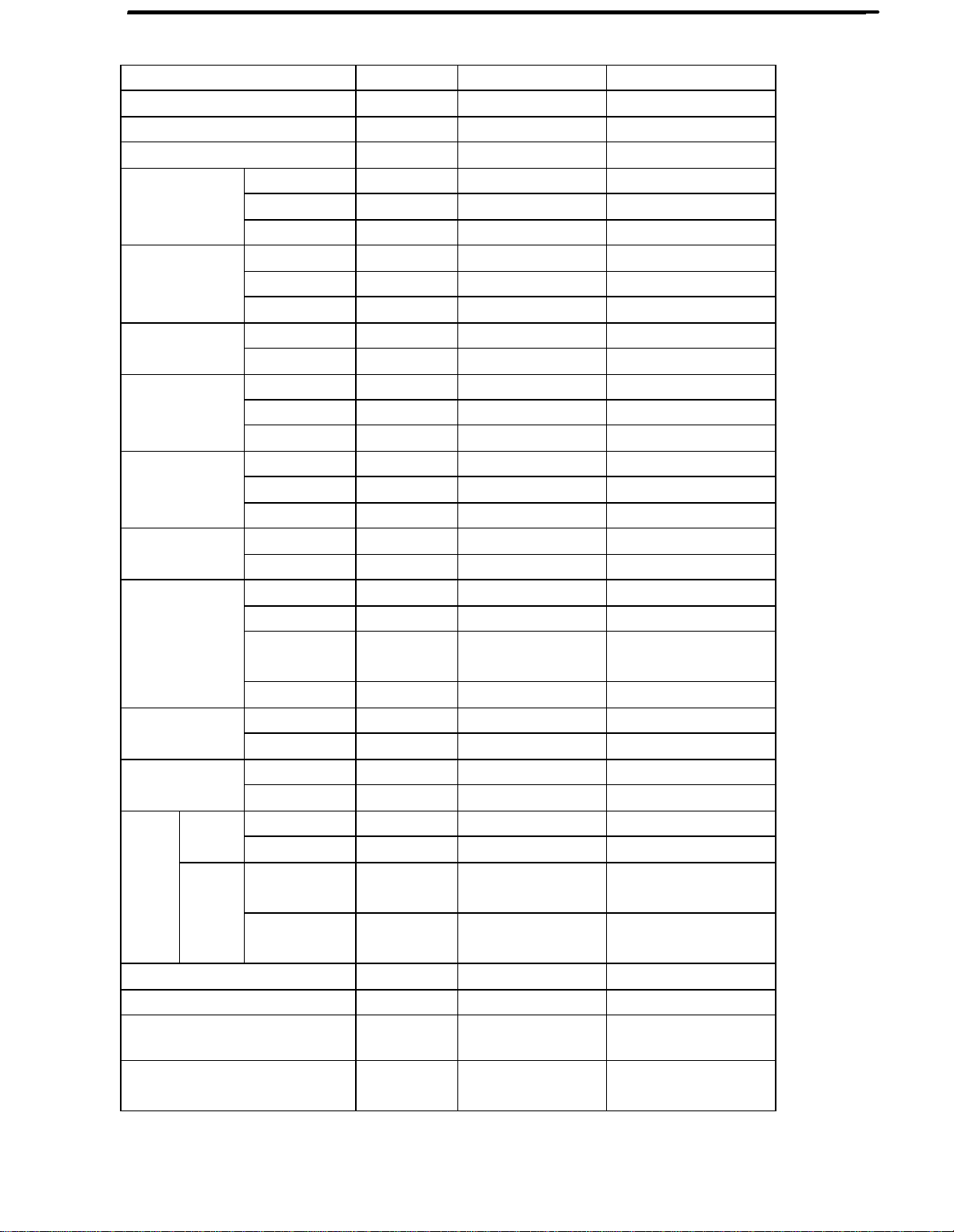
Specifications:
Item UNIT ACB055E ACB065R
Cooling capacity BTU/h
Heating capacity BTU/h
Power supply
Power input
Cooling
Heating
Sound Level
Case
Packaging dimensions
Weight
Compressor
Pressure
Refrigerant
Type
Fan
Fan speed
Air volume m3/hr
Moisture removal Pints/hr
Exchanging pipe type/ diameter mm
Fin material
Running current
EER
Power input
Running current
COP
Indoor side dB(A)
Outdoor side dB(A)
Height
Width
Depth
Height
Width
Depth
Net kg
Gross kg
Type
Model
Running cap. for
comp.
Starting method
Heating side MPa
Cooling side MPa
Model
Charge kg
indoor unit
outdoorunit
indoor unit r/min
outdoorunit r/min
BTU/(hW) 10.7 9.7
BTU/(hW) / /
W 485 620
A 4.5 5.4
W / /
A / /
mm
mm
mm
mm
mm
mm
μF
5000 6000
/ /
1PH/115V/60Hz 1PH/115V/60Hz
53/52/50 53/52/50
/ 57/55/53
315 472
471 340
340 326
373 535
535 416
416 373
21 21
24 24
Rotate
SD074UW
35uf/200VAC
Rotate
SD086SW-H3BX
35uf/250VAC
PSC PSC
380 380
170 170
R22 R22
0.32 0.36
Acentric fan
Acentric fan
Axial fan Axial fan
1040±30/950
±
40/800±50
1040±30/950
±
40/800±50
280 280
1.8ⅹ10-3 2.0ⅹ10-3
Evaporator
: ф
7condenser: ф7
Hydrophile
aluminum foil
1040±30/950±40/850
±
50
1040±30/950±40/850
±
50
Evaporator
: ф7
condenser: ф7
Hydrophile
aluminum foil
3
Page 6
Safety and Precaution
4
Page 7

Warning and Cautions
5
Page 8

Net Dimention
326
472 340
6
Page 9

Installation and Accessory Parts
7
Page 10

Installation and Accessory Parts
ASSEMBLE
CURTAINS/TOP RAIL
Install top rail with 3 short
screws13/32".
Insert the side curtains into the
top and bottom rails of the air
conditioner. Fasten the curtains
to the unit with 8 short screws
13/32".
ACB065R,ACB055E
3
5
25
3
12
5
2
13
5
1
33
5
1
22
2
7
12
16
9
18
16
3
13
8
8
Page 11

2
1. This unit is designed for installation in standard double hung windows
with actual opening widths of 22 to 36 . The upper and lower sash
must open sufficiently to allow a clear vertical opening of 14 from the
bottom of the sash to the window stool.
2. If storm window presents interference, fasten a 2 wide wood strip(not
included) (OUTER SILL) to the inner window sill across the full width of
the sill. The wood strip should be thick enough to raise the height of
the window sill so that the unit can be installed without interference by
the storm window frame (STORM WINDOW FRAME) or wood strip
(OUTDOORS) to help condensation to drain properly to the outside.
3. Install a second wood strip (approximately 6 long by 3/2 wide and
same thickness as first strip) in the center of the outer sill flush against
the back off the inner sill. This will raise basepan angle .
4. If the distance between STORM WINDOW FRAME and WOOD STRIP
MOUNTED ON TOP OF INNER SILL is more than 1 , two of wood
strip are not necessary.
LOCATING UNIT IN
WINDOW
Open the window and mark center line on the
center of the inner sill.
Install the basepan angle behind the inner window sill, with
the short side of basepan angle as shown. Use the 2 short
screws13/32" provided.
The basepan angle helps to hold unit securely in place.
Be sure to place basepan angle edge flush against back
of inner sill.
INNER
SILL
I
N
D
O
O
R
S
WOOD STRIP
MOUNTED ON
TOP OF INNER SILL
INNER
SILL
I
N
D
O
O
R
S
1 MAX.
WOOD STRIP
FOR BASEPAN
ANGLE
ATTACH BASEPAN
ANGLE
OUTER
SILL
3/4 CLEARANCE
OUTER
SILL
O
U
T
D
O
O
R
S
STORM
WINDOW FRAME
O
U
T
D
O
O
R
S
INNER SILL
INDOOR SIDE
CENTER LINE
OUTER SILL
SHORT SIDE
OUTSIDE
INNER SILL
8
BASEPAN ANGLE
SHORT SCREW13/32"
CENTER LINE
INSIDE
8
9
Page 12

Installation and Accessory Parts
INSTALL THE AIR CONDITIONER
IN THE WINDOW
Carefully lift the air conditioner and slide it into the open
window . Make sure the bottom guide of the air conditioner
drops into the notches of the basepan angle.
While steadying the air conditioner ,carefully bring the
window sash down behind the upper guide of the air
conditioner.
WINDOW FRAME
UPPER GUIDE
ABOUT 1/4
INSTALL THE SEAL GASKET
AND SASH LOCK
Extend the side curtains to fill the
window opening using 4 wood screws
31/32" to secure them.
Cut the seal gasket to the window
width. Stuff the sash seal between the
glass and the window to prevent air
a nd insects from getting into the room.
Fasten the basepan angle, using a
short screw13/32".
BOTTOM GUIDE
BASEPAN ANGLE
SHORT SCREW13/32"
WOOD SCREW31/32"
BASEPAN ANGLE
WINDOW SEAL GASKET
10
Page 13

Installation and Accessory Parts
wood screws 31/32"
short screws 13/32"
window seal gasket
Model :ACB065R, ACB055E
ON/ OFF
MODE SPEED TIMER
TEMP/TIME
control
top rail
“CR2025“ batteryRemote
11
Page 14

Parts and Functions
2-way airfl ow
MODE SPEE D TIM ER
FAN O NHIG H
O FFCOO L
LO W
T EMP / TIME
POWE R
ON/ O FF
filters
MODEL: ACB065R, ACB055E
1. Thermostat
T his all ows you to adjust the temperature of the air.
T he lower the setting the cooler the air temperature
W ith this you can set the temperature to your
desired comfort level You can set the temperature
between 61oF and 86oF.
2. fan Speed
You have 2 l evels of Fan speed to set at your
desired comfort level.
3. Function.
Your air conditioner has 2 Functions.
a) CO OL
Here the air conditioner wil l operate the compressor
and the desired fan speed set to give you chil led
col d air for your comfort.
b) Fan
You can run the fan only on not so hot days. The
fan can be set to run at 2 speeds as desired by you.
4. Timer
Your air conditioner can be set to go on or off at
your desi re. This can be done up to 24 hours in
advance.
5. 2 Way Air Flow
T hese air directional louvers let you control the direction
of the airflow in your required direction.
T he ai rflow can be directed right side -- left side.
control p aneleasy access
6. Window Install Kit
Enables you to instal l the air conditioner in a double
hung window. Extra brackets or support may be
needed depending on your window.
7. Remo te Control
Thi s full functional wireless remote allows you to
operate your air conditi oner from a distance. You
need not have to get up to change the settings, the
functi ons or to turn the unit on or off.
8. LE D Disp lay Electro nic Control Panel
The 4 function LED di splays Room Temperature,
Temperature Set ting, Timer Setting and Time
Remaini ng to Stop / Start the unit. Electronic
Control P anel lets you set the temperature to the
Exact Temperature you desire.
9. Electrostatic Fi lter
Being constructed of high efficiency purifying
substance, active carbon fabric, el ectrostatic fabric,
electrostatic active carbon net and other m aterials
it puri fies the air effectively. Its wavy structure
increases the capabi lity to filter dust and smoke
effectively. Due to the retention of the active carbon
it has a hi gh purifying speed capable of
strong airflow.
12
Page 15

Abnormity Diagnose
1. Sensor diagnose: 2 seconds after the sensors open circuit or short
circuit, the unit will turn off automatically and the LED will show E0 until
the sensors resume.
2. Keystroke circuit error diagnose: When power on for the first time, the
PCB will check the keystroke circuit, if the sampling value is different with
the theory value, the LED will show E1, which means failed keystroke
circuit. The keyboard is locked and so invalid, but the remote control is
working normally.
13
Page 16

System Flow Chart
heat exchanger
Capacillary tube
Indoor
heat exchanger
Outdoor
Compressor
Cooling
14
Page 17

Circuit Diagram
A
D
D
C
B
+5
15
14
13
12
11
10
CN3
9
8
7
6
5
4
3
2
1
R84.7k
R74.7K
+5
C10
104C9100UF/16V
R1222k
R1322k
C16
104
1
3
5
6
7
8
R15
10k
R14
10K
CX1
4M
+12
C17
100UF/16V
IC22003
A1
Q1
A22Q2
Q3
A3
A44Q4
Q512A5
Q6
A6
A7
Q7
GND
VCC
C5
100UF/16V
1
2
3
4
5
6
7
8
9
10
11
12
13
R11
1K
16
15
14
13
11
10
9
C6
104
IC1 TMP86C807
VSS
XIN
XOUT
TEST
VDD
P33(AIN1)
P21(XTIN)
P32(AIN0)
P22(XTOUT)
/RESET
P20
P12(/DVO)
P00(TXD)
P11(INT1)
P01(RXD)
P10(/INT0)
P02(SCLK)
P03(MOSI)
P04(MISO)14P05(/SS)
+5
PB1
R18 560
R10
2K
R9
1K
P37
P36
P35
P34
P31
P30
P07
P06
R19
2.2K
87654321
R212K
DQ2
9012
10
123
456789
GF ABCEDH
POWER ON/OFF
R421KR41
REV
3
2
1
+5V
DQ1
9012
L1 L2
LED1
POWER ON/OFF HIGHTIMER ONTIMER OFFUV-LIGHT
K2K1
TEMP/TIME -TEMP/TIME+UV-LIGHT
R321KR332KR342KR35
1K
+5V
R39
330
R40
C21
10K
4.7UF/50V
R36
3K
DQ4
9012
L10
R38
10K
L11
FANCOOL
C
B
L7
LOW
K7K6K5K4K3
MODESPEEDTIMER
R37
10K
DQ3
9012
L3
L4
L5
2K
R222K
R302K
R312K
C15
102
28
27
26
25
24
23
22
21
20
19
18
17
16
15
R16
2.2K
Q1
9012
R17
C11
10K
104
CN20
15
14
13
12
11
10
9
8
7
6
5
4
3
2
1
+5V
C22
C20
104
100U/16V
R23 330
R24 330
R25
R26 330
R27 330
R28 330
R29 330
VCC
GND
OUT
330
JK3
JK1
LOW HIGH
N
A
S5S4S2
JK4
L
FUSE1
COMPRESSOR
L1
+12
+5
R20
C7
10K
R4 10K R310K
4.7UF/50V
R43
5.1K
R5
+5
5.1K
1
2
1
2
CN1
Å̹ÜÎÂ¶È ÊÒÎÂ
CN4
UV
C13
+5
ZR1
S1
1
C14
0.1u/250V
C1
104
D1 D2
D3 D4
C2
1000UF/25V
TRANS
12
34
C8
4.7UF/50V
C12
104
104
R6
+5
5.1K
1
2
CN2
+5
C3
104
3
C4
470UF16V
RG1 7805
Vin
Vout
2
1
1 2 3 4 5 6 7 8
15
Page 18

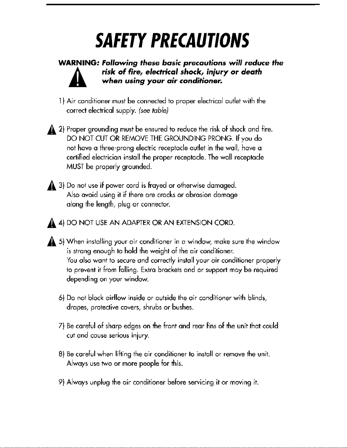
Maintenance Service and Trouble Shooting
URE
TEMPERA
T
6
5
4
7
8
3
2
9
0
1
1
MIN
MAX
OOL
COO
L
C
FAN ONL
Y
LOW
PEE
D
OF
F
POWER
Always unplug your air conditioner before cleaning.
The air filter behind the front grille should be checked and
cleaned at least once every 2 weeks or more often if necessary.
T o remove:
1. Open the inlet grille downward by pulling out the top of the inlet grille.
2. Remove the air filter from the front grille assembly by pulling the air filter
up slightly.
3. Clean the filter with warm, soapy water below 40oC(104oF).
4. Rinse and gently shake the water from the filter and let it dry before replacing
it.
DO NOT use your air conditioner without the air filter in place.
To clean the front panels or the cabinet DO NOT use harsh
chemicals, abrasives, ammonia, chlorine, bleach, concentrated
detergents, solvents or metal scouring pads.
Always use a soft cloth dampened with water or mild soap
and water solution to wipe the front of the cabinet.
16
Page 19

Maintenance Service and Trouble Shooting
Trouble Shooting
If air conditioner does not operate:
●Check if unit is plugged in.The plug may have come loose.
●Check if the unit is in “off” mode.
●The fan control may be in “off” position.
Air from air conditioner is warm:
●The A/C setting may need to be raised.
●The temperature outside the room is below 65°F。The conpressor will not
cycle on if the temperature outside is below 65°F.
Ice formation on cooling coils:
●Outside temperature too cold .Set the unit on fan only setting to defrose ice.
●Lower temperature setting.Temperature setting may be too cold.
●Unit BTU may be too high for the room.
17
Page 20

Wiring Diagram
B: BLACK
BL: BLUE
GR:GRAY
R: RED
W: WHITE
OR:ORANGE
BR:BROWN
G:GREEN
G/Y:GREEN/
YELLOW
POWER SUPPLY
WIRING DIAGRAM
W(or Ribbed)
N
G (or G/Y)
L
B(or Plain)
TRANSFORMER
T3.15A/250VAC
4
FUSE
3
COMPRESSOR RELAY
UV
LIGHT
CN4
OR
B
L
S2
M
~
H
GR
R
S4
FAN MOTOR
BL
S1
R
HEAT
PROTECTOR
FAN
HERM
W
0010552088
C
DUAL
CAPACITOR
S
M
R
~
C
COMPRESSOR
R
AMBIENT
TEMP. SENSOR
AMBIENT
PIP. SENSOR
CN2
CN1
CN3
LED
CN20
NOTE:
BECAUSE OF DIFFERENT COMPRESSOR,
THE DOTTED PART MAY NOT BE USED.
18
 Loading...