

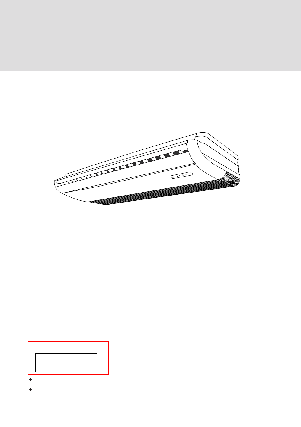
CONVERTIBLE TYPE AIR CONDITIONER
Operation & Installation
Manual
AC282AFEAA
AC362AFEAA
AC482AFEAA
AC602AFEAA
No. 0010577967
B
Please read this operation manual before using the air conditioner.
Please keep this manual carefully and safely.
AC282AFERA
AC362AFERA
AC422AFERA
AC522AFERA

Contents
Cautions
Safety Precautions
Features and Functions
Name of Parts
Cleaning and Care
Operation Tips
Installation of Indoor Unit
Trouble Shooting..............
...........................................................................
...........................................................
...................................................
.....................................................................
..............................................................
.................................................................
...........................................
...........................................
1-2
3-4
5-7
8
9
10
11-24
25-28
Cautions
Disposal of the old air conditioner
Before disposing an old air conditioner that
goes out of use, please make sure it's
inoperative and safe. Unplug the air
conditioner in order to avoid the risk of
child entrapment.
It must be noticed that air conditioner
system contains refrigerants, which require
specialized waste disposal. The valuable
materials contained in a air conditioner can
be recycled. Contact your local waste
disposal center for proper disposal of an
old air conditioner and contact your local
authority or your dealer if you have any
question. Please ensure that the pipework
of your air conditioner does not get
damaged prior to being picked up by the
relevant waste disposal center, and
contribute to environmental awareness by
insisting on an appropriate, anti-pollution
method of disposal.
Disposal of the packaging of your new
air conditioner
Consult your local authorities for the name and
address of the waste materials collecting centers
and waste paper disposal services nearest to
your house.
Safety Instructions and Warnings
Before starting the air conditioner, read the
information given in the User's Guide
carefully. The User's Guide contains very
important observations relating to the
assembly, operation and maintenance of the
air conditioner.
The manufacturer does not accept
responsibility for any damages that may arise
due to non-observation of the following
instruction.
Damaged air conditioners are not to be put
into operation. In case of doubt, consult your
supplier.
Use of the air conditioner is to be carried
out in strict compliance with the relative
instructions set forth in the User's Guide.
All the packaging materials employed in
the package of your new air conditioner
may be disposed without any danger to the
environment.
The cardboard box may be broken or cut
into smaller pieces and given to a waste
paper disposal service. The wrapping bag
made of polyethylene and the polyethylene
foam pads contain no fluorochloric
hydrocarbon.
All these valuable materials may be taken to a
waste collecting center and used again after
adequate recycling.
1
Installation shall be done by professional
people, don't install unit by yourself.
For the purpose of safety, the air
conditioner must be properly grounded in
accordance with specifications.
Always remember to unplug the air
conditioner before opening inlet grill.
Always grip plug firmly and pull straight
out from the outlet.
Cautions
All electrical repairs must be carried out
by qualified electricians. Inadequate repairs
may result in a major source of danger for
the user of the air conditoiner.
Do not damage any parts of the air
conditioner that carry refrigerant by
piercing or perforating the air conditioner's
tubes with sharp or pointed items, crushing
or twisting any tubes, or scraping the
coatings off the surfaces. If the refrigerant
spurts out and gets into eyes, it may result
in serious eye injuries.
Do not obstruct or cover the ventilation
grille of the air conditioner. Do not put
fingers or any other things into the
inlet/outlet and swing louver.
Do not allow children to play with the air
conditioner. In no case should children be
allowed to sit on the outdoor unit.
When the indoor unit is turned on,the
PCB will test if swing motor is O.K.,and
then fan motor will start up.So there is a
few seconds to wait .
In cooling mode,the flaps will swing
automatically to a fixed position for anticondensating.
Specifications
The refrigerating circuit is leak-proof.
For this model, the all-pole discon-rexion
connection method should be applied in
the power supply.
Such means for disconnection must be
incorporation in the fixed wiring.
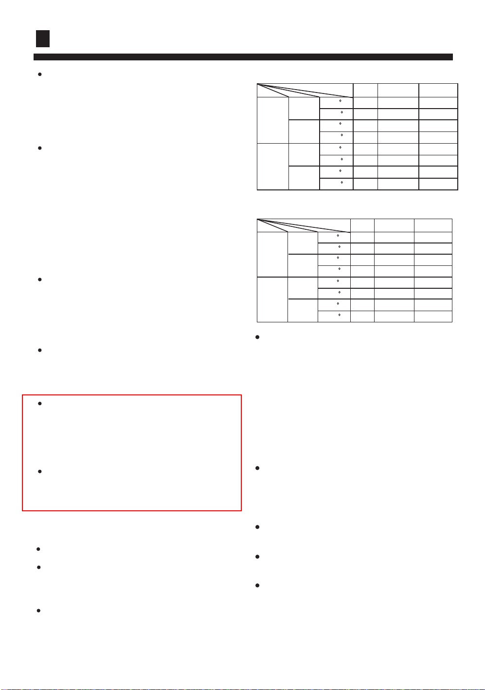
Temperature and Humidity Range
*EAA :
Rated Maximum Minimum
27 32 18
19 23 14
35 43 10
24 26 - 20 27 15
14.5 -- - 7 24 -7
6 18 --
Cooling
Heating
Indoor
outdoor
Indoor
outdoor
DB C
WB C
DB C
WB C
DB C
WB C
DB C
WB C
*ERA :
Rated Maximum Minimum
27 32 18
19 23 14
35 43 -5
24 26 - 20 27 15
14.5 -- - 7 24 -15
6 18 --
Cooling
Heating
Indoor
outdoor
Indoor
outdoor
DB C
WB C
DB C
WB C
DB C
WB C
DB C
WB C
If the air conditioner is used under higher
temperature condition than those listed,
the built-in protection circuit may operate
to prevent internal circuit damage. Also,
during Cooling and Dry modes, if the unit
is used under conditions of lower
temperature than those listed above, the
heat-exchanger may freeze, leading to
water leakage and other damage.
Do not use this unit for any other purposes
except for the Cooling and the Heating,
Dehumidifying, and air-circulation of
rooms should be in ordinary dwellings.
The wiring method should be in line with
the local wiring standand.
The waste battery should be disposed
properly.
If the fuse on PC board is broken, please
change it with the type T 3.15A/250VAC.
The air breaker should be all-pole switch.
and the distance between it's two contacts
should no less than 3mm.
2
Safety Precautions
WARNING!
The breaker of the air conditioner should be all-pole switch; and the distance between its
two contacts should be no less 3 mm. Such means for disconnection must be
incorporation in the fixed wiring.
Use copper wire only. All the cables shall have got the European authentication certificate.
The power supply connects from the outdoor side. The connecting cable and the power
cable are self-provided.
The parameter of connecting cable: H05RN-F 4G 0.75mm2 .
The paramter of Indoor and Outdoor unit:T3.15A/250VAC.If the fuse on PC board is
broken, please change with the type.
DANGER!
Do not attempt to install this air conditioner by yourself.
This unit contains no user-serviceable parts. Always consult authorized service personnel
for repairs.
When moving, consult authorized service personnel for disconnection and installation of
the unit.
Do not become excessively chilled by staying for lengthy periods in the direct cooling
airflow.
Do not insert fingers or objects into the outlet port or intake grills.
Do not start and stop air conditioner operation by connecting and disconnecting the
power supply cord and so on.
Take care not to damage the power supply cord. If the supply card is damaged, it must be
replaced by the manufacturer or authoried service agent in order to avoid a hazard.
In the event of a malfunction (burning smell, etc.), stop operation immediately, turn off
the circuit breaker, and consult authorized service personnel.
3
Safety Precautions
WARNING!
Provide occasional ventilation during use.
Do not direct air flow at fire places or heating apparatuses.
Do not climb on and place objects on the air conditioner.
Do not hang objects from the indoor unit.
Do not set flower vases or water containers on top of the air conditioner.
Do not expose the air conditioner directly to water.
Do not operate the air conditioner with wet hands.
Do not pull power supply cord.
Turn off power source when not using the unit for extended periods.
Check the condition of the installation stand for damage.
Do not place animals or plants in the direct path of the air flow.
Do not drink the water drained from the air conditioner.
Do not use in applications involving the storage of foods, plants or animals, precision
equipment, or art works.
Do not apply any heavy pressure to radiator fins.
Operate only with air filters installed.
Do not block or cover the intake grill and outlet port.
Ensure that any electronic equipment is at least one metre away from either the indoor
or outdoor unit.
Avoid installing the air conditioner near a fireplace or other heating apparatuses.
When installing the indoor and outdoor unit, take precautions to prevent access to infants.
Do not use inflammable gases near the air conditioner.
4
Features and Functions
AUTOMATIC OPERATION
COOLING TYPE
Merely press the ON/OFF button, and the unit will begin automatic operation in the Cooling
or dry modes as appropriate, in accordance with the thermostat setting and the actual temperature
of the room.
HEAT & COOL TYPE
Merely press the ON/OFF button, and the unit will begin automatic operation in any of the
Heating, Cooling and Blow modes as appropriate, in accordance with the thermostat setting and
the actual temperature of the room.
SLEEP
COOLING TYPE
When the SLEEP button is pressed during Cooling or Dry mode, the thermostat setting
gradually rises during the period of operation. When the set time is reached, the unit
automatically turns off.
HEAT & COOL TYPE
When the SLEEP button is pressed during Heating mode, the air conditioner's thermostat
setting gradually lowers during the period of operation; When the set time is reached, the
unit automatically turns off.
WIRELESS REMOTE CONTROL UNIT
The WIRELESS REMOTE CONTROL UNIT allows convenient control of air conditioner
operation.For this type unit, the wireless remote controllor type is YR-H50.
MILDEW-RESISTANT FILTER
The AIR FILTER has been treated to resist mildew growth, thus allowing cleaner use and
easier care.
5
Features and Functions
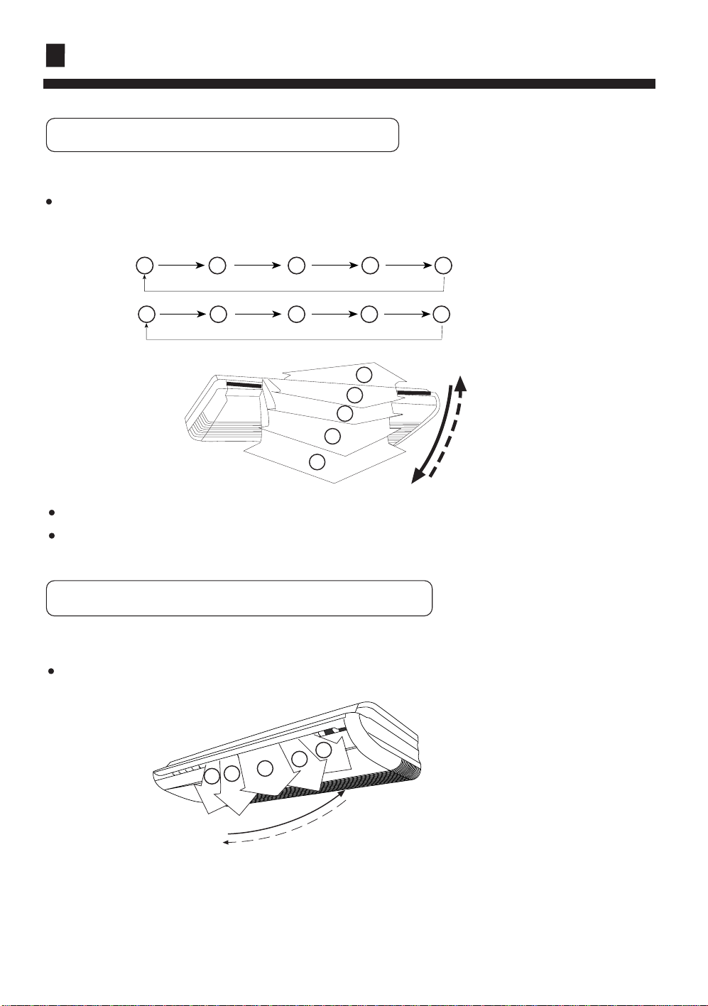
VERTICAL AIR DIRECTION ADJUSTMENT
Press the AIR FLOW DIRECTION VERTICAL SET button.
Each time the button is pressed, the air direction range will change as follows:
Cool/Dehumidification/Fan:
4
2
1
2
3
4
5
1
Heat:
1
5
2 3
4 3
5
Use the air direction adjustment within the ranges shown above.
The vertical airflow direction is set automatically as shown, in accordance with the type of
operation selected.
HORIZONTAL AIR DIRECTION ADJUSTMENT
Press the AIR FLOW DIRECTION HORIZONTAL SET button.
Use the air direction adjustments within the ranges shown above.
5
4
3
2
1
6
Features and Functions
The swing range of up-down flap is as follow :
1
2
3
4
5
Air flow direction set Range of swing
1
2
3
4
5
1
1
2
3
1
to5(all range)
to
to
to
to
3
3
4
5
Each time the button is pressed, the air direction range will change as follows:
1
3
2 3
2
5
1
4
1
5
24
RIGHT/LEFT
air direction louvers
4 5
Note :
When being switched on firstly, the up-down flap will be at the position of max.angle.
In cooling, the up-down louver is not good to stay at position 4, 5 for along time,
otherwise, the dew will occur.
7
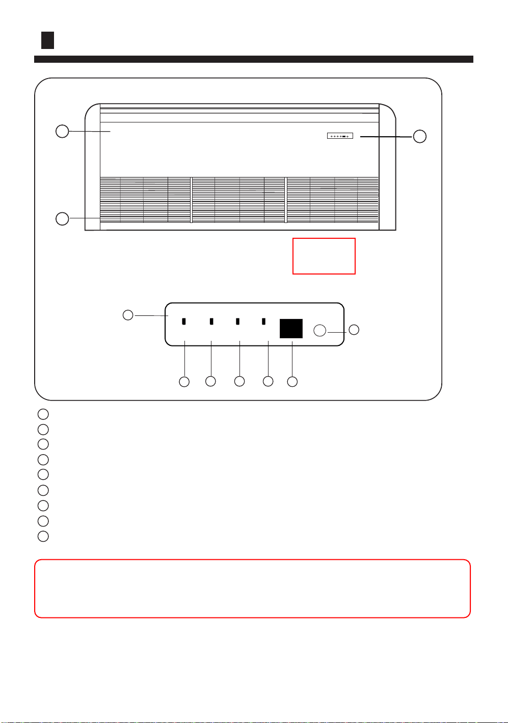
Name of Parts
9
8
for series 282, 362, 422, 482, 522,602
1
POWER OPER TIMER
1 Operating Control Panel
2 Emergency switch
3 Power Indicator Lamp
4 OPERATION Indicator Lamp
5 TIMER Indicator Lamp
6 Compressor Lamp
7 Remote receiver
8 Inlet Grill ( Filter inside )
9 Front panel
1
EMER
COMP
4
3
5 6
7
2
Note : For the wired control type unit, the unit state should be checked by the the wired
controller, instead of the remote receiver; and if you set the TIMER function, the
TIMER LED on the remote receiver will not be on.
8

Cleaning and Care
The following four procedures are for series 282, 362, 422, 482, 522,602.
1. Pull the filters upward to remove them from the Intake Grill.
2. Clean the air filter: Remove the dust from the filters by vacuum cleaner or washing them.
After washing, allow the air filters to dry thoroughly in an area protected from sunlight.
3. Re-attach the air filters to the Intake Grill, press the two buttons on the filters, until you hear
a sound of click.
When used for extended periods, the unit may accumulate dirt inside, which reduces its
performance. We recommend that the unit is inspected regularly, in addition to your own
cleaning and care. For more information, consult authorized service personnel.
When cleaning the unit's body, do not use water hotter than 40 C, harsh abrasive
cleansers, or volatile agents like benzene or thinner.
Do not expose the unit body to liquid insecticides or hairsprays.
When shutting down the unit for one month or more, first allow the Fan mode to operate
continuously for about half a day to allow internal parts to dry thoroughly.
o
9

Operation Tips
Operation and Performance
*Heating Performance
This air conditioner operates on the heat-pump
principle, absorbing heat from outdoor air and
transferring that heat indoors. As a result, the
operating performance is reduced as outdoor air
temperature drops. If you feel that insufficient
heating perfomance is being produced, we
recommend you use this air conditioner in
conjunction with another kind of heating
appliance.
Heat-pump air conditioners heat your entire
room by recirculating air throughout the room,
with the result that some time may be required
after first starting the air conditioner until the
room is heated.
Instructions relating to heating (*) are applicable
only to "HEAT & COOL TYPE".
*Microcomputer-controlled Automatic Defrosting
STANDARD PARTS
The following installation parts are furnished.
Use them as required.
Optional parts
Mark Parts name
A
B
C
D
E
F
G
Adhesive tape
Saddle (L.S) with screws
Drain hose
Heat insulation material
Piping hole cover
Putty
Plastic clamp
When using the Heating mode under
conditions of low outdoor air temperature high
humidity, frost may form on the outdoor unit,
resulting in reduced operating performance.
In order to prevent this kind of reduced
performance, this unit is equipped with a
Microcomputer-controlled Automatic
Defrosting function. If frost forms, the air
conditioner will temporarily stop, and the
defrosting circuit will operate briefly (for
about 7 to 15 minutes).
10

Installation of Indoor Unit
Please ask the dealer or specialist to install, never try by the users themselves. After the installation please
be sure of the following conditions.
WARNING !
Please call dealer to install the air-conditioner.
Incorrect installation may cause water leaking, shock and fire hazard.
CAUTION !
Air-conditioner can't be installed in the environment with inflammable gases because the
inflammable gases near to air-conditioner may
cause fire hazard.
Installed electrical-leaking circuit breaker.
It easily cause electrical shock without circuit
breaker.
[Location]
Air-conditioner should be located in well-vented
and easily-accessible place.
Air-conditioner should not be located in the
following places:
(a) Places with machine oils or other oil vapours.
(b) Seaside with high salt content in the air.
(c) Near to hot spring with high content of sulfide
gases.
(d) Area with frequent fluctuation of voltage e.g.
factory, etc.
(e) In vehicles or ships.
(f) Kitchen with heavy oil vapour or humidity.
(g) Near to the machine emitting electric-magnetic
waves.
(h) Places with acid, alkali vapuor.
TV, radio, acoustic appliances, etc. are at least 1
m far away to the indoor unit, outdoor unit, power
Connect earthing wire.
Earthing wire should not be connected to the gas pipe, water pipe,
lightning rod or phone line, incorrect earthing may cause shock.
Use discharge pipe correctly to ensure efficient
discharge.
Incorrect pipe use may cause water leaking.
supply wire, connecting wire, pipes, otherwise
images may be disturbed or noises be created.
As required, take measures against heavy snow.
Earthing
[Wiring]
Air-conditioner should be equipped with special
power supply wire.
[Operating noise]
Choose the following locations:
(a) Capable of supporting air-conditioner weight,
don't increase operating noise and vibration.
(b) Hot vapour from outdoor unit outlet and ope rating noise don't disturb neighbour.
No obstacles around the outdoor unit outlet.
11
Installation of Indoor Unit
For authorized service personnel only
WARNING
(1) For the room air conditioner to operate satisfactorily, install it as outlined in this
installation manual.
(2) Connect the indoor unit and outdoor unit with the room air conditioner piping and
cords available from our standard parts. This installation manual describes for the
correct connections so that the installation set available from our standard parts should
be used.
(3) Installation work must be performed in accordance with national wiring standards
by authorized personnel only.
(4) Never cut the power cord, lengthen or shorten the cord, or change the plug.
(5) Also, do not use an extension cord.
(6) Plug in the power cord plug firmly. If the receptacle is loose, repair it before using
the room air conditioner.
(7) Do not turn on the power until all installation work is done.
Be careful not to scratch the room air conditioner when handing it.
After installation, explain correct operation to the customer, according to the operating
manual.
Let the customer keep this installation manual because it will be used when the room
air conditioner is serviced or moved.
1. SELECTING THE MOUNTING POSITION
WARNING
Install at a place that can withstand the weight of the indoor unit and install it
positively so that the unit will not topple or fall.
CAUTION
Do not install the unit where there is the danger of combustible gas leakage.
Do not install near heat sources.
If children under 10 years old may approach the unit, take preventive measures so
that they cannot reach the unit.
12

Installation of Indoor Unit
(1) Install the indoor unit level on a strong wall which is not subject to vibration.
(2) The inlet and outlet ports should not be obstructed : the air should be able to blow all
over the room.
(3) Do not install the unit where it will be exposed to direct sunlight ,
(4) Install the unit where connection to the outdoor unit is easy.
(5) Install the unit where the drain pipe can be easily installed.
(6) Take servicing , etc.into consideration and leave the spaces shown in (Fig.1 or 2) .
Also install the unit where the filter can be removed .
Fig. 1
Ceiling
INDOOR UNIT
3"(80mm)
over
FOR HALF CONCEALED INSTALLATION
Fig. 2
INDOOR UNIT
6"(150mm)
over
0.4"(10mm)
over
Ceiling panel
3"(80mm)
over
6"(150mm)
over
Ceiling panel
0.4"(10mm)
over
13

Installation of Indoor Unit
CONNECTION PIPE REQUIREMENT
Table 1
Model
For series 362*EAA),422,482,
522, 602
For series 282, 362(ERA)
Diameter
Liquid side Gas side
9.52 mm 19.05mm
9.52 mm 15.88mm
INST ALLA TION PROCEDURE
Install the room air conditioner as follows:
1. REMOVE THE INTAKE GRILL AND SIDE COVER
(1) Remove the Air filters
(2) Remove the intake grilles
(3) Remove the Side cover A (Right and left side)
(4) This air conditioner can be set up to intake
fresh air . For information about how to install for
fresh-air intake, refer to page 22 "FRESH-AIR INTAKE".
2. LOCATION OF CEILING SUSPENSION BOLTS
Fig. 3
30mm
Suspension bolt pitch 1530mm
30mm
Maximum
length
Dimensions
(Space Required for
installation)
10mm
155mm
Maximum height
(between indoor
and outdoor)
50 m
30 m 20 m
Side cover A (Right side) Side cover A (Left side)
30 m
Air filter
Intake grille
INDOOR UNIT (TOP VIEW)
Suspension bolt should
extend outward 30 to 50mm.
300mm
For half-concealed installation
Supension-bolt pitch should be as shown in Fig.4.
Fig. 4
40mm 40mm
Ceiling Opening:640mm
Ceiling Opening:1530mm
15mm
Ceiling panel
14
Ceiling panel
Suspension bolt should
extend outward 30 to 50mm.

Installation of Indoor Unit
3. DRILLING THE HOLES AND ATTACHING THE SUAPENSION BOLTS
(1) Drill 25mm holes at the suspension-bolt locations.
(The two special nuts are provided with the unit. The M10 nut must be obtained locally.)
Refer to Fig.5.
(2) Install the bolts, then temporarily attach Special nuts A and B and a normal M10 nut
to each bolt.
**
Fig. 5
Bolt Strength
Ceiling panel
980 to 1470 N (100 TO 150 kgf)
Special nut A (included)
10 to 15 mm
Special nut B (included)
M10 nut (Obtained locally)
IF USING ANCHOR BOLTS
(1) Drill holes for anchor bolts at the locations at which you will set the suspension bolts.
Note that anchor bolts (to be obtained locally).
(2) Install the anchor bolts ,then temporarily attach special nut "B" (included) and a
locally-procurde M10 nut to each of the bolts. (See Fig.6.)
Anchor-Bolt Strength 980 to 1470 N (100 to 150 kgf)
Fig. 6
Special nut B
(included)
M10 Nut
M10 Nut
(Obtaied locally)
10 to 15 mm
(Obtaied locally)
INSTALLING THE INDOOR UNIT
(1) Lift unit so that suspension bolts pass through suspension fittings at the sides (four
places),and slide the unit back.(See Fig.8.)
15

Installation of Indoor Unit
Fig. 7 Fig. 8
Ceiling
Ceiling panel
Wall
Wall
(2) Fasten the indoor unit into place by tightening-up the special "B",blots and the M10
nuts. Make sure that unit is secure and willl not shift back and forth.
FOR HALF-CONCESLED INSTALLATION
When installing the indoor unit in a semi-concesled orientation, make sure to reinforce the
insulation of the unit on all sides. Drops of water may fall from the unit if it is not
thoroughly insulated.
Fig. 9
INDOOR UNIT
(Top view)
Glass wool insulate
(10 to 20mm thick )
Wall
Ceiling pannel
CAUTION
In order to check the drainage, be sure to use a level during installation of the indoor
unit. If the installation site of the indoor unit is not level, water leskage may occur
16

Installation of Indoor Unit
INSTALLING THE COUPLER HEAT INSULATION
After checking for gas leaks, insulate by wrapping insulation around the two parts (large
and small) of the indoor unit coupling, using the coupler hest insulation.
After installling the coupler heat insulation, wrap both ends with vinyl tape so that there
is no gap.
Secure both ends of the heat insulation material using nylon fasteners.
Fig. 10
Indoor unit
Indoor unit
Coupler heat insulation(large)
Coupler pipe (large)
Coupler pipe (small)
Coupler heat insulation(small)
Nylon fastner (large)
No gap
Coupler heat insulation
Nylon fastner (small)
When using an auxiliary pipe, make sure that the fastener used is insulated in the
sane way.
Notice
When installing the unit on the floor, fix the four rubber base feet in the accessories on
the bottom plate of the unit with four 4x16 screws and 4 flat washers,as the position in
the figure.
A
The bottom plate of the unit.
17
A
4:1
rubber base foot
4x16 screw
flat washer

Installation of Indoor Unit
DRAIN PIPING
Install the drain pipe with downward gradient (1/50 to 1/100) and so there are no rises or
traps in the pipe.
Use general hard polyvinyl chloride pipe (VP25)[outside diameter 38 mm.]
During installation of the drain pipe,be careful to avoid applying pressure to the drain
point of the unit.
When the pipe is long,install supporters(Fig 11).
Do not perform air bleeding.
Always heat insulate (8mm or over thick) the indoor side of the drain pipe.
Fig. 11
GOOD
BAD
Supporter
BAD
5 to 6.5 ft
(1.5 to 2m)
18

Installation of Indoor Unit
(1) Install insulation for the drain pipe.(See Fig.12 and 13)
Cut the included insulation material to an appropriate size and adhere it to the pipe.
Fig. 12
Drain pipe
Insulation for Drain pipe
(To be obtained locally.Length shoud
be at least 8mm.)
Drain pipe insulation (accessories)
Indoor unit(drain port)
Fig. 13
Drain pipe insulation
Indoor unit
No gap
10mm or over
Drain pipe
(2) If "Right rear piping ":fasten the drain pipe with VT wires so that the pipe slopes
correctly within the indoor unit.
19

Installation of Indoor Unit
ELECTRICAL WIRING
HOW TO CONNECT WIRING TO THE TERMINALS
A.For solid core wiring (or F-cable)
(1)Cut the wire and with a wire cutter or wire-cutting pliers,then strip the insulation to
about 15/16"(25mm) of expose the solid wire.
(2)Using a screwdriver ,remove the terminal screw(s) on the terminal board.
(3)Using pliers,bend the solid wire to form a loop suitable for the terminal screw.
B.For strand wiring
(1)Cut the wire and with a wire cutter or wire-cutting pliers,then strip the insulation to
about 3/8"(10mm) of expose the solid wire.
(2)Using a screwdriver ,remove the terminal screw(s) on the terminal board.
Fig. 14
Wire
A. Solid wire
Insulation
Strip 15/16"(25mm)
Round
terminal
Loop
Screw with
special washer
Terminal
board
B. Strand wire
Round terminal
Strip 15/16"(25mm)
Screw with
special washer
Round
terminal
Wire
HOW TO FIXED CONNECTION CORD AND POWER CABLE AT THE CORD
CLAMP
After passing the connection cord and power cable through the insulation tube, fasten
it with the cord clamp, as shown in Fig.15
20

Installation of Indoor Unit
ELECTRICAL REQUIREMENT
Electric wire size and fuse capacity:
Select wire sizes and circuit protection from table below. (This table shows 20 m
length wires with less than 2% voltage drop.)
Table 5
Power source
wire size
(minimum)
(mm2)
Earth leakage breaker
Switch
breaker(A)
current(mA)
Model
Item
Phase
Circuit breaker
Switch breaker
(A)
Overcurrent protector
rated capacity (A)
Leak
For series 282, 362
For series 282(EAA),
362
For series 422,482*
522, 602
Fig. 15
1 40 26 6.0
3 30 2.5 3020 30
3
30 20 4.0
40
30
Insulation tube
Cord clamp
Use VW-1, 0.5 to 1.0 mm thick, PVC tube as the insulation tube.
CAUTION
(1) Match the terminal block numbers and connection cord colors with those of the
outdoor unit.
Erroneous wiring may cause burning of the electric parts.
30
20
(2) Connect the connection cords firmly to the terminal block. Imperfect installation
may cause a fire.
(3) Always fasten the outside covering of the connection cord with the cord clamp.
(If the insulator is chafed, electric leakage may occur.)
(4) Always connect the ground wire.
21

Installation of Indoor Unit
FRESH-AIR INTAKE
(1)Open up the knockout hole for the fresh-air intake,as shown in Fig.16 (If using
half-concealed installation ,open up the top knockout hole instead)
Fig. 16
(1)When removing the cabinet(iron plate),be careful not to damage the indoor unit
internal parts and surrounding area(outer case).
(2)When processing the cabinet(iron plate),be careful not to injury yourself with
burrs,etc.
For half-concealed
CAUTION
(2)Fasten the round flange (optional) to the fresh air intake,as shown in Fig.17 (If using
half-concealed installation, attach to the top.)
Fig. 17
Round duct (option parts)
[After completing " INDOOR UNIT INSTALLATION"....]
(3)Connect the duct to the round flange.
(4)Seal with a band and vinyl tape,etc.so that air does not leak from the connection.
Fig. 18
Duct
22

Installation of Indoor Unit
(1) Remove the cord clamp.
(2) Process the end of the connection cords
to the dimensions shown in Fig.19.
(3) Connect the end of the connection cord
fully into theterminal block.
(4) Fasten the connection cord with a cord clamp.
(5) Fasten the end of the connection cord with the screw.
(6) The power cable and connecting cable are self-provided.
Fig. 19
For three phase (380-400V, 3N~, 50Hz),outdoor unit.
INDOOR UNIT
TERMINAL BLOCK
OUTDOOR UNIT
TERMINAL BLOCK
For single phase (1PH, 220-230V~, 50Hz),outdoor unit.
OUTDOOR UNIT
TERMINAL BLOCK
R S T
POWER SUPPLY:
380-400V, 3N~,50Hz
INDOOR UNIT
TERMINAL BLOCK
L N
POWER
1PH,220-230V~,50Hz
SUPPLY:
N 1 2 3
1 2 3
1 2 3
1 2 3
Y/G
Y/G
Y/G
Y/G
WARNING
(1) Always use a special branch circuit and install a special receptacle to supply power to the room air
conditioner.
(2) Use a circuit breaker and receptacle matched to the capacity of the room air conditioner.
(3) The circuit breaker is installed in the permanent wiring. Always use a circuit that can trip all the
poles of the wiring and has an isolation distance of at least 3mm between the contacts of each pole.
(4) Perform wiring work in accordance with standards so that the room air conditioner can be
operated safely and positively.
(5) Install a leakage circuit breaker in accordance with the related laws and regulations and electric
company standards.
23

Installation of Indoor Unit
CAUTION
(1) The power source capacity must be the sum of the room air conditioner current and the current
of other electrical appliances. When the current contracted capacity is insufficient, change the
contracted capacity.
(2) When the voltage is low and the air conditioner is difficult to start, contact the power company
the voltage raised.
TEST RUNNING
1. CHECK ITEMS
(1) INDOOR UNIT
(1) Is operation of each button on the remote control unit normal?
(2) Does each lamp light normally?
(3) Do not air flow direction louvers operate normally?
(4) Is the drain normal?
(2) OUTDOOR UNIT
(1) Is there any abnormal noise and vibration during operation?
(2) Will noise, wind, or drain water from the unit disturb the neighbors?
(3) Is there any gas leakage?
CUSTOMER GUIDANCE
Explain the following to the customer in accordance with the operating manual:
(1) Starting and stopping method, operation switching, temperature adjustment, timer, air flow switching, and
other remote control unit operations.
(2) Air filter removal and cleaning, and how to use air louvers.
(3) Give the operating and installation manuals to the customer.
24

Trouble Shooting
Followings are not problems
Sound of water flowing is
not a problem.
Sound of cracking is heard.
Smell are generated.
During operation, white fog or steam
comes out from the indoor unit.
In cooling operation, unit switches to
blowing operation.
Unit will not restart after stop.
Won't start?
During unit operation or at stop, a swishing or
gurgling noise may be heard. This noise is generated
by refrigerant flowing in the system.
During unit operation, a cracking noise may be heard.
This noise is generated by the casing expanding or
shrinking because of temperature changes.
This is because the system circulates smells from the
interior air such as the smell of cigarettes or the
painting on the furniture.
When unit is running at places like restaurant, etc. where
dense edible oil fumes always exist, this will happen.
To prevent frost from accumulating on indoor heat
exchanger, unit will switch to blowing operation for a
while then resume cooling operation.
Though ON/OFF button is set
to ON, unit won't resume cooling,
dry or heating operation
in 3 min after it is stopped, this
is because of 3-min-delay
protection circuit.
Please wait 3 minutes
No outlet air or fan speed can't be changed
in dry mode.
In heating operation, water or steam are
blown out of outdoor unit.
In heating operation, indoor fan won't stop
even if unit is stopped.
Unit will reduce fan speed repeatedly and automatically
if room temp. is too low in dry operation.
This occurs when frost accumulated
on the outdoor unit is removed.
(during defrosting operation)
After unit stop, indoor fan will go on running
until indoor unit cools down.
25

Trouble Shooting
Before ask for services, please first check your unit against the following.
Air conditioner won't start.
Is power supply switch
turned on?
Power supply switch
is not set at ON.
Are operation control
adjusted correctly
as specified?
Proper
temp
Is city power supply normal? Is leakage current breaker
activated?
This is very dangerous, please
Power
failure?
disconnect power supply
immediately and contact your
dealer.
Poor cooling or heating
Is air filter too dirty?
Are there any obstacles in inlet
or outlet grill?
Are horizontal louvers at up
position (in heating mode)?
Any doors or windows left
open?
Poor cooling
Is there any direct sunlight
in the room?
Cold air blows out
(in heating mode)
Is air conditioner in standby
condition in heating mode?
If your unit still can't work properly after above mentioned checks, or following problems occur,
please stop it immediately and contact your dealer.
Fuses or circuit breakers often blow out.
Water comes out in cooling/dry operation.
Operation is abnormal or sound is heard.
If there are unexpected heat
sources in the room?
Too many people in the room?
26

Trouble Shooting
Error display ( For *ERA series )
Remarks
Resumable if
lower than 100
degree
Reason
Failure description
For central
Failure code
For remote
Sensor broken down or short circuit for more than 2m continuously
Sensor broken down or short circuit for more than 2m continuously
Sensor broken down or short circuit for more than 2m continuously
Indoor ambient temp. sensor failure
Indoor coil temp. sensor failure
Outdoor ambient temp. sensor failure
control,
failure code
01D
02D
on wired
controller
01(01H)
02(02H)
type, flash
times12
3
Sensor broken down or short circuit for more than 2m continuously
Outdoor coil temp. sensor failure
11D
12D
74(4AH)
73(49H)
4
Fault phase, short of phase, out of balance greatly
CT check abnormal 3 times in 30m
High pressure switch acts 3 times in 30m
Over-current protection
High pressure abnormal
10D
14D
72(48H)
83(53H)
567
Communication abnormal for more than 4m continuously
Communication abnormal for more than 4m continuously
Float switch broken down for more than 25m continuously
Outside signal broken down for more than 10s
Sensor broken down or short circuit for more than 2m continuously
Solenoid valve act incorrectly 3 times continuously
Sensor broken down or short circuit for more than 2m continuously
EEPROM data missing
Power supply abnormal
Communication between wired
controller and indoor abnormal
Communication between indoor and outdoor abnormal
Drainage system abnormal
Outside alarm signal input
Gas pipe temp. sensor abnormal
Temperature protection malfunction
Discharging temp. sensor abnormal
EEPROM abnormal
22D
06D
05D
21D
30D
20D
31D
15D
17D
71(47H)
07(07H)
06(06H)
08(08H)
11(0BH)
03(03H)
13(0DH)
76(4CH)
05(05H)
8
9
10111213141516
Low pressure switch acts in normal running
The discharging temperature is higher than 120degree
Pressure abnormal(low pressure)
Compressor overheat
26D
15D
84(54H)
80(50H)
17
Indoor operation mode is different with the running indoor unit.
Sensor broken down or short circuit for more than 2m continuously
Sensor broken down or short circuit for more than 2m continuously
Spdu module temperature is too high
Abnormal mode
Outdoor coil B(suction temp sensor-for MRV II)
Outdoor discharging B(oil temp sensor-for MRV II)
SPDU module temperature protection
23D
18D
15D
07D
12(0CH)
75(4BH)
77(4DH)
20(32D)
shows resumable fault, shows it is not resumable fault.
181920
21
27

Trouble Shooting
Error display ( For *EAA series )
Remarks
Resumable if
lower than
100 degree
Reason
Failure description
For central
Failure code
Sensor broken down or short circuit for more than 2m continuously
Sensor broken down or short circuit for more than 2m continuously
Sensor broken down or short circuit for more than 2m continuously
Indoor ambient temp. sensor failure
Indoor coil temp. sensor failure
Outdoor ambient temp. sensor failure
control,
failure code
01D
02D
11D
on wired
controller
01(01H)
02(02H)
74(4AH)
Sensor broken down or short circuit for more than 2m continuously
CT check abnormal 3 times in 30m / Fault phase, short of phase,
out of balance greatly
High pressure switch acts 3 times in 30m/Low pressure switch acts
in normal running
Communication abnormal for more than 4m continuously
Communication abnormal for more than 4m continuously
Float switch broken down for more than 25m continuously
Outside signal broken down for more than 10s
Sensor broken down or short circuit for more than 2m continuously
Solenoid valve act incorrectly 3 times continuously
EEPROM data missing
Outdoor coil temp. sensor failure/Compressor
discharging temp. sensor abnormal
Over-current protection / Power supply
abnormal
High/Low pressure abnormal
Communication between wired
controller and indoor abnormal
Communication between indoor and outdoor abnormal
Drainage system abnormal
Outside alarm signal input
Gas pipe temp. sensor abnormal
Temperature protection malfunction
EEPROM abnormal
12D
10D
14D
06D
05D
21D
30D
20D
31D
17D
73(49H)
72(48H)
83(53H)
07(07H)
06(06H)
08(08H)
11(0BH)
03(03H)
13(0DH)
05(05H)
Indoor operation mode is different with the running indoor unit.
The discharging temperature is higher than 120degree
Compressor overheat
15D
80(50H)
Sensor broken down or short circuit for more than 2m continuously
Sensor broken down or short circuit for more than 2m continuously
Abnormal mode
Outdoor coil B(suction temp sensor-for MRV II)
Outdoor discharging B(oil temp sensor-for MRV II)
23D
18D
15D
12(0CH)
75(4BH)
77(4DH)
For remote
type, flash
times12
3
4
5
6
8
9
1011121315
17
181920
shows resumable fault, shows it is not resumable fault.
28

HAIER GROUP
Qingdao Haier Air Conditioner Electric Co., Ltd.
Address: Haier Garden ,Qianwangang Road , Economic Development Zone,
Qingdao ,Shandong 266500, P.R.China
Web Site: http://www.haier.com
 Loading...