

Haier AU182ABNAC, AC242ACNAC, AU242ABNAC, AC28NACNAC, AU28NABNAC Service Manual
...
HCFU-14CL03/R1 (AC142ACNAC+AU142ABNAC)
HCFU-18CL03/R1 (AC182ACNAC+AU182ABNAC)
HCFU-24CL03/R1 (AC242ACNAC+AU242ABNAC)
HCFU-28CM03/R1 (AC28NACNAC+AU28NABNAC)
HCFU-36CM03/R1 (AC36NACNAC+AU36NABNAC)
HCFU-42CM03/R1 (AC42NACNAC+AU42NABNAC)
MANUAL CODE: SYJS-006 EDITION:2002.12.31.
Haier Group
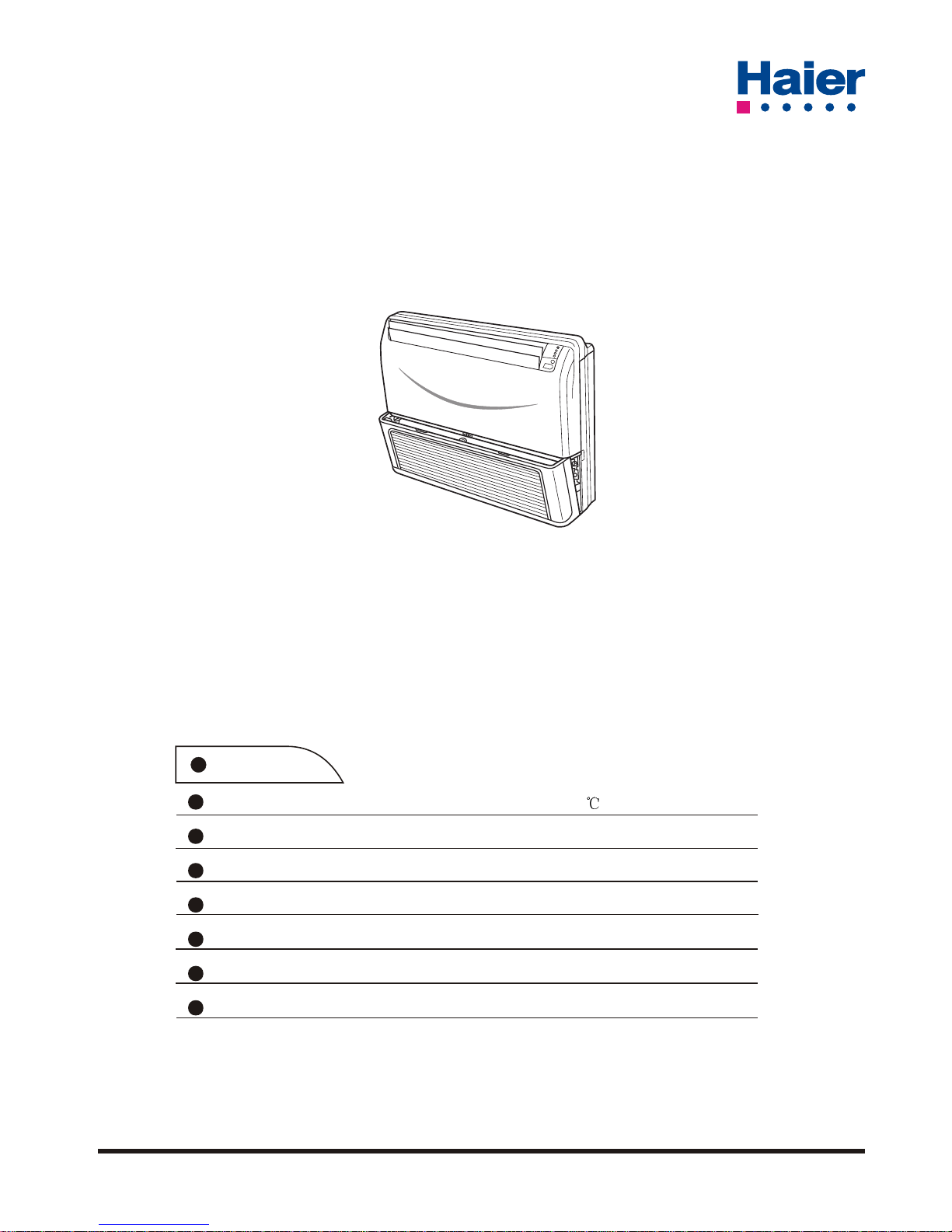
Super low outdoor ambient cooling at -15
Auto-restart function
Group control(with a group controller)
Auto-changeover
Compact design of indoor unit
Weekly timing(with a weekly timer)
With new environment friendly refrigerant R407C
Features
Service Manual
Commercial Air Conditioning
Convertible Type Low Ambient Cooling Series

CONTENTS
1. Description of Products & Features…………………...…….1
2. Specifications…………………………. ………………...……3
3. Safety precaution…………………………..………………….9
4. Net dimensions of indoor and outdoor unit………………...11
5. Installation instructions ……………………. ………………..17
6. Parts and functions …………………………..…… ..……….28
7. Remote controller functions………………………….………31
8. Refrigerant diagram…………………………..……………....43
9. Electrical control functions……………………………………44
10. Diagnostic information(trouble shooting)…………….……51
11. Electrical data.........................................…………….……56
12. Exploded views and parts lists...............……………. ……67
13. Perdormance curves……………............................... ……87
14. Noise level charts.....……………............................... ……93
15. Air velocity distribution …………............................... ……94
CONTENTS
Contents……..............................................…...………...…….1
- 1 -
1 DESCRIPTION OF PRODUCTS & FEATURES
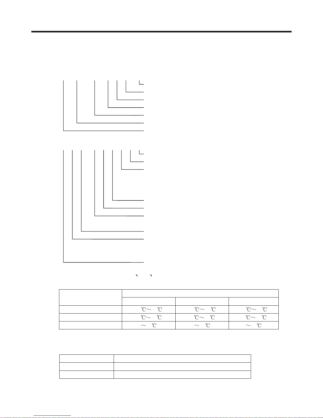
1.1 Products coding direction
Old code
H CFU – 42 C M 03 / R1
Refers to HFC refrigerant
Power: 03(230V/50Hz).04(240V/50Hz).12(115V/60Hz).13(230v/60Hz)
Low ambient cooling
“H” refer to cooling and heating, ”C” refer to cooling only
Nominal cooling capacity (BTU/h), 42=42000BTU/h
Indoor and outdoor unit code: "CF" Convertible type; "U" Outdoor unit
“H” means “Haier”
New code
A C 42 N A C N A C
Climate type: T1 (see table 1), and -15 degree cooling
Design number (A stands for fix speed type)
Product type: A stands for heat pump type, refrigerant is R22
B stands for heat pump type, refrigerant is R407
M stands for cool only type, refrigerant is R22
N stands for cool only type, refrigerant is R407
Appearance character
Product series: one by one type
Applicable voltage: 2 stands for 220-240V/50Hz,4 stands for 220v/60Hz
N stand for 380V/50Hz
Cooling / Heating capacity,42=42000BTU/h
Product type : “B” stands for cassette type, “C” stands for convertible
type, ”D” stands for duct, “S” stands for split type, ”Q” stands for chiller
system, "E" stands for ceiling concealed type, “U” stands for outdoor unit
Air conditioner
1.2 Brief Introduction to T1 T2 T3 working condition
Table 1
Climate type
Type of Air Conditioner
T1 T2 T3
Cool only
18
43 10 35 21 52
Heat pump
-7
43 -7 35 -7 52
Electricity heating
43 35 52
1.3 Operating Range of air conditioners
Low ambient cooling
Operation Operation Range Outside / Inside
Cooling
-15
0
C – 43oC
Dehumidifying
-15
0
C – 43oC
DESCRIPTION OF PRODUCTS & FEATURES
- 2 -

1.4 Products characteristic
(2).HFC refrigerant technology
To protect the environment, we have adopted the HFC refrigerant. The HFC R407C is of zero ODP
for the purpose of environmental protection.
(3).Ceiling/console convertible,flexible installation,convenient maintenance,saving
the users' expenditures
(4).Adopting single-phase or three-phase power supply,applicable for household
and commercial usage
(5).Dual air outlet design,floor air blowing,accelerating the indoor air circulation,
quick temperature adjustment
(6).Long-distance air blowing,large power,large cooling/heating ratio
(7).Intelligent remote control,convenient and flexible control
(8).Super-slim indoor unit design,luxury and nice-looking,saving space,harmonious
and unitive with the indoor environment
(9).Adopting screw-fastening for the air inlet grill,firmly fixed;adopting slipway
insert-lock fastening method for the filter screen,convenient cleaning or replacing
the filter screen without opening the air inlet grill.
.
The system can run the cooling operation at the low ambient temperature -15
(1).Low ambient temperature cooling technology
(10).Group control,units up to 128 sets can be controlled
DESCRIPTION OF PRODUCTS & FEATURES
- 3 -

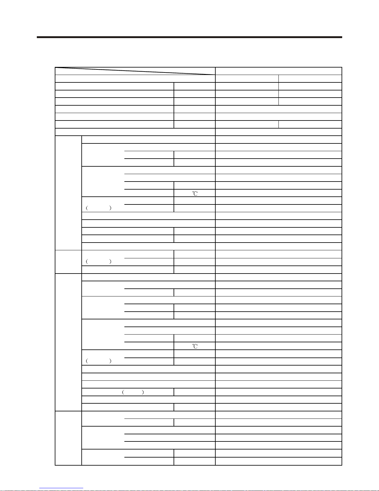
Function
Cooling Heating
Capacity BTU/h
14000 /
W
2000 /
EER or COP BTU/W
7.00 /
Dehumidifying capacity
10‐³×m³/h
Power source PH-V-Hz
Running current/Starting current
A
Power cable
Unit model (color)
Fan Type × Number
Speed r/min
Air-flow(H-M-L) m³/h
Heat exchanger Type / Diameter
Flow
Total area m²
Temp. scope
External mm×mm×mm
Package mm×mm×mm
Drainage pipe (material , I.D./O.D.)
Control type (wireless/wired)
Fresh air hole dimension mm
Noise level (H-M-L) dB(A)
kg
External mm×mm×mm
Package mm×mm×mm
kg
Unit model (color)
Compressor Model / Manufacture
Type
Fan Type × Number
Speed r/min
Air-flow(H-M-L) m³/h
Heat exchanger Type / Diameter
Flow
Total area m²
Temp. scope
External mm×mm×mm
Package mm×mm×mm
Drainage pipe (material , I.D./O.D.)
Refrigerant control method
Noise level
H-M-L
dB(A)
kg
Refrigerant Type
Charge kg
Pipe Liquid mm
Gas mm
Connect method
Drop
m
Piping length
m
Item Model
HCFU-14CL03/R1
1
1PH, 220V-230V, 50HZ
/
Indoor unit
AC142ACNAC / WHITE
CENTRIFUGAL×2
1070/1000/940
900
TP2M/9.52
2/2
0.199
2-7
Dimension
L×W×H
900×655×199
1150×750×300
PVC 18/20
wired
/
48/44/38
Weight (net / gross)
30/39
Panel
Dimension
L×W×H
/
/
Weight (net / gross)
/
Outdoor unit
AU142ABNAC / WHITE
ZR34K3E-TFJ-522 / COPELAND
scroll
Axial-flow×1
820
700/-/-
TP2M/9.52
2/2
0.225
43-60
Dimension
L×W×H
810×288×680
960×406×760
PVC,18/20
Capillary
Defrosting
Auto
15.88
FLARED
52/-/
Four way valve
/
Between
I.U. & O.U.
MAX :5
MAX :15
Total power input
Weight (net / gross)
59/66
Piping
R407C
1.8
6.35
2 SPECIFICATIONS
9.4/40.7
/
SPECIFICATIONS
- 4 -
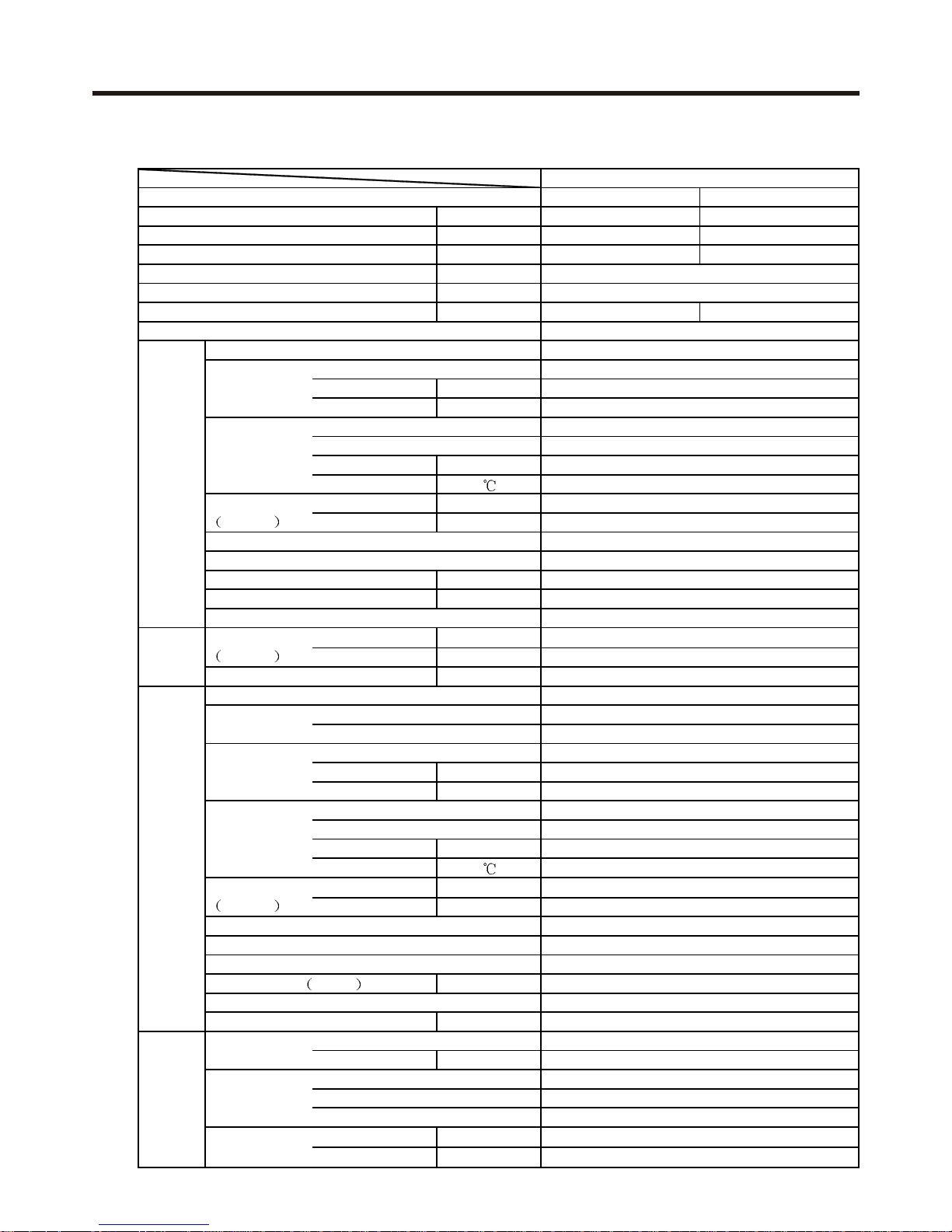
Function
Cooling Heating
Capacity BTU/h
18000 /
W
2000
/
EER or COP BTU/W
9
.00 /
Dehumidifying capacity
10‐³×m³/h
Power source PH-V-Hz
Running current/Starting current A
Power cable
Unit model (color)
Fan Type × Number
Speed r/min
Air-flow(H-M-L) m³/h
Heat exchanger Type / Diameter
Flow
Total area m²
Temp. scope
External mm×mm×mm
Package mm×mm×mm
Drainage pipe (material , I.D./O.D.)
Control type (wireless/wired)
Fresh air hole dimension mm
Noise level (H-M-L) dB(A)
kg
External mm×mm×mm
Package mm×mm×mm
kg
Unit model (color)
Compressor Model / Manufacture
Type
Fan Type × Number
Speed r/min
Air-flow(H-M-L) m³/h
Heat exchanger Type / Diameter
Flow
Total area m²
Temp. scope
External mm×mm×mm
Package mm×mm×mm
Drainage pipe (material , I.D./O.D.)
Refrigerant control method
Noise level
H-M-L
dB(A)
kg
Refrigerant Type
Charge kg
Pipe Liquid mm
Gas mm
Connect method
Drop
m
Piping length
m
Item Model
HCFU-18CL03/R1
1
1PH, 220V-230V, 50HZ
/
Indoor unit
AC182ABNAC / WHITE
CENTRIFUGAL×2
500/450/380
1050
TP2M/9.52
2/2
0.
199
2-7
Dimension
L×W×H
990×655×199
1160×760×310
PVC 18/20
wired
/
43/42/40
Weight (net / gross)
29/39
Panel
Dimension
L×W×H
/
/
Weight (net / gross)
/
Outdoor unit
AU182ABNAC / WHITE
ZR34K3E-TFJ-522 / COPELAND
scroll
Axial-flow×1
820
700/-/-
TP2M/9.52
2/2
0.225
43-60
Dimension
L×W×H
810×288×680
960×406×760
PVC,18/20
Capillary
Defrosting
Auto
15.88
FLARED
52/-/46
Four way valve
/
Between
I.U. & O.U.
MAX :
5
MAX :
15
Total power input
Weight (net / gross)
58/66
Piping
R407C
1.80
6.35
/
9.3/46.0
SPECIFICATIONS
- 6 -

Function
Cooling Heating
Capacity BTU/h
24000 /
W
2800 /
EER or COP BTU/W
8.57 /
Dehumidifying capacity
10‐³×m³/h
Power source PH-V-Hz
Running current/Starting current A
Power cable
Unit model (color)
Fan Type × Number
Speed r/min
Air-flow(H-M-L) m³/h
Heat exchanger Type / Diameter
Flow
Total area m²
Temp. scope
External mm×mm×mm
Package mm×mm×mm
Drainage pipe (material , I.D./O.D.)
Control type (wireless/wired)
Fresh air hole dimension mm
Noise level (H-M-L) dB(A)
kg
External mm×mm×mm
Package mm×mm×mm
kg
Unit model (color)
Compressor Model / Manufacture
Type
Fan Type × Number
Speed r/min
Air-flow(H-M-L) m³/h
Heat exchanger Type / Diameter
Flow
Total area m²
Temp. scope
External mm×mm×mm
Package mm×mm×mm
Drainage pipe (material , I.D./O.D.)
Refrigerant control method
Noise level
H-M-L
dB(A)
kg
Refrigerant Type
Charge kg
Pipe Liquid mm
Gas mm
Connect method
Drop
m
Piping length
m
Item Model
HCFU-24CL03/R1
3
1PH,220V~230V,50Hz
/
Indoor unit
AC242ACNAC / WHITE
CENTRIFUGAL×2
1300/1200/1000
1300
TP2M/9.52
2/2
0.221
2-7
Dimension
L×W×H
1320×715×235
1380×770×300
PVC 18/20
wired
/
35/32/29
Weight (net / gross)
40/57
Panel
Dimension
L×W×H
/
/
Weight (net / gross)
/
Outdoor unit
AU242ABNAC / WHITE
ZR34K3E-TFJ-522 / Copeland
scroll
Axial-flow×1
840/-/-
3240
TP2M/9.52
3/3
0.62
43-60
Dimension
L×W×H
948×830×340
1050×979×440
PVC,18/20
Capillary
Defrosting
Auto
15.88
FLARED
58/-/50
Four way valve
/
Between
I.U. & O.U.
MAX :15
MAX : 30
Total power input
Weight (net / gross)
70/85
Piping
R407C
1.85
9.52
12.5/60.1 /
SPECIFICATIONS

Function
Cooling Heating
Capacity BTU/h
28000 /
W
28
00 /
EER or COP BTU/W
10.0 /
Dehumidifying capacity
10‐³×m³/h
Power source PH-V-Hz
Running current/Starting current A
Power cable
Unit model (color)
Fan Type × Number
Speed r/min
Air-flow(H-M-L) m³/h
Heat exchanger Type / Diameter
Flow
Total area m²
Temp. scope
External mm×mm×mm
Package mm×mm×mm
Drainage pipe (material , I.D./O.D.)
Control type (wireless/wired)
Fresh air hole dimension mm
Noise level (H-M-L) dB(A)
kg
External mm×mm×mm
Package mm×mm×mm
kg
Unit model (color)
Compressor Model / Manufacture
Type
Fan Type × Number
Speed r/min
Air-flow(H-M-L) m³/h
Heat exchanger Type / Diameter
Flow
Total area m²
Temp. scope
External mm×mm×mm
Package mm×mm×mm
Drainage pipe (material , I.D./O.D.)
Refrigerant control method
Noise level
H-M-L
dB(A)
kg
Refrigerant Type
Charge kg
Pipe Liquid mm
Gas mm
Connect method
Drop
m
Piping length
m
Item Model
HCFU-28CM03/R1
3
3N,380V~400V,50Hz
/
Indoor unit
AC28NACNAC / WHITE
CENTRIFUGAL×2
1300/1200/1000
1300
TP2M/9.52
2/2
0.221
2-7
Dimension
L×W×H
1320×715×235
1380×770×300
PVC 18/20
wired
/
35/32/29
Weight (net / gross)
40/57
Panel
Dimension
L×W×H
/
/
Weight (net / gross)
/
Outdoor unit
AU28NABNAC / WHITE
ZR34K3E-TFJ-522 / Copeland
scroll
Axial-flow×1
840/-/-
3240
TP2M/9.52
3/3
0.62
43-60
Dimension
L×W×H
948×830×340
1050×979×440
PVC,18/20
Capillary
Defrosting
Auto
15.88
FLARED
58/-/50
Four way valve
/
Between
I.U. & O.U.
MAX :
15
MAX :
30
Total power input
Weight (net / gross)
74/89
Piping
R407C
1.85
9.52
12.5/60.1 /
SPECIFICATIONS
Function
Cooling Heating
Capacity BTU/h
36000 /
W
3600 /
EER or COP BTU/W
10.0 /
Dehumidifying capacity
10‐³×m³/h
Power source PH-V-Hz
Running current/Starting current A
Power cable
Unit model (color)
Fan Type × Number
Speed r/min
Air-flow(H-M-L) m³/h
Heat exchanger Type / Diameter
Flow
Total area m²
Temp. scope
External mm×mm×mm
Package mm×mm×mm
Drainage pipe (material , I.D./O.D.)
Control type (wireless/wired)
Fresh air hole dimension mm
Noise level (H-M-L) dB(A)
kg
External mm×mm×mm
Package mm×mm×mm
kg
Unit model (color)
Compressor Model / Manufacture
Type
Fan Type × Number
Speed r/min
Air-flow(H-M-L) m³/h
Heat exchanger Type / Diameter
Flow
Total area m²
Temp. scope
External mm×mm×mm
Package mm×mm×mm
Drainage pipe (material , I.D./O.D.)
Refrigerant control method
Noise level
H-M-L
dB(A)
kg
Refrigerant Type
Charge kg
Pipe Liquid mm
Gas mm
Connect method
Drop
m
Piping length
m
Item Model
HCFU-36CM03/R1
5
3N, 380V-400V, 50HZ
/
Indoor unit
AC36NACNAC / WHITE
CENTRIFUGAL×3
1300/1200/1000
1600
TP2M/9.52
3/3
0.338
2-7
Dimension
L×W×H
1920×715×235
1980×761×295
PVC 18/20
wired
/
56/54/52
Weight (net / gross)
46/52
Panel
Dimension
L×W×H
/
/
Weight (net / gross)
/
Outdoor unit
AU36NABNAC / WHITE
ZR34K3E-TFJ-522 / COPELAND
scroll
Axial-flow×2
840/-/-
6000
TP2M/9.52
5/5
0.92
43-60
Dimension
L×W×H
948×1225×340
1050×1375×440
PVC,18/20
Capillary
Defrosting
Auto
19.05
FLARED
52/-/46
Four way valve
/
Between
I.U. & O.U.
MAX :30
MAX : 50
Total power input
Weight (net / gross)
85/111
Piping
R407C
3.1
9.52
6.4/32
/
SPECIFICATIONS

Function
Cooling Heating
Capacity BTU/h
42000 /
W
4600 /
EER or COP BTU/W
9.1
Dehumidifying capacity
10‐³×m³/h
Power source PH-V-Hz
Running current/Starting current A
Power cable
Unit model (color)
Fan Type × Number
Speed r/min
Air-flow(H-M-L) m³/h
Heat exchanger Type / Diameter
Flow
Total area m²
Temp. scope
External mm×mm×mm
Package mm×mm×mm
Drainage pipe (material , I.D./O.D.)
Control type (wireless/wired)
Fresh air hole dimension mm
Noise level (H-M-L) dB(A)
kg
External mm×mm×mm
Package mm×mm×mm
kg
Unit model (color)
Compressor Model / Manufacture
Type
Fan Type × Number
Speed r/min
Air-flow(H-M-L) m³/h
Heat exchanger Type / Diameter
Flow
Total area m²
Temp. scope
External mm×mm×mm
Package mm×mm×mm
Drainage pipe (material , I.D./O.D.)
Refrigerant control method
Noise level
H-M-L
dB(A)
kg
Refrigerant Type
Charge kg
Pipe Liquid mm
Gas mm
Connect method
Drop
m
Piping length
m
Item Model
HCFU-42CM03/R1
5
3N, 380V-400V, 50HZ
/
Indoor unit
AB42NACNAC / WHITE
CENTRIFUGAL×3
980/880/820
2040
TP2M/9.52
3/3
0.199
2-7
Dimension
L×W×H
1920×715×235
1980×761×295
PVC 18/20
wireless
/
43/41/39
Weight (net / gross)
46/53
Panel
Dimension
L×W×H
/
/
Weight (net / gross)
/
Outdoor unit
AU42NAANAC / WHITE
ZR34K3E-TFJ-522 / COPELAND
scroll
Axial-flow×2
840/-/-
6000
TP2M/9.52
5/5
0.92
43-60
Dimension
L×W×H
948×1225×340
1050×1375×440
PVC,18/20
Capillary
Defrosting
Auto
19.05
FLARED
64/-/-
Four way valve
/
Between
I.U. & O.U.
MAX :30
MAX : 50
Total power input
Weight (net / gross)
85/111
Piping
R407C
3.2
9.52
/
/
9.3/32
SPECIFICATIONS
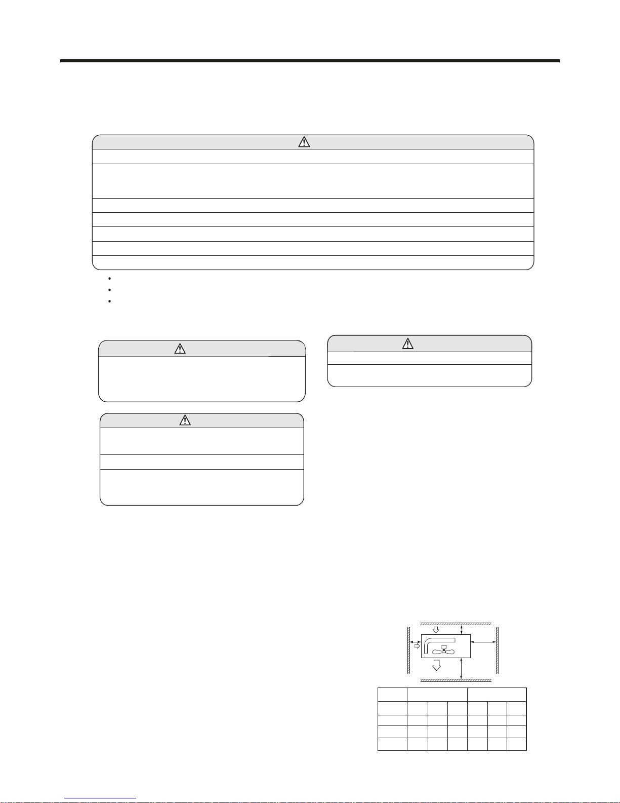
WARNING
CAUTION
WARNING
CAUTION
This system should be applied to places of office, restaurant, residence and the like. Appliaction to inferior
environment such as engineering shop could cause equipment malfunction.
Please entrust installation to either the company which sold you the equipment or to a professional contractor.
Defects from improper installations can be the cause of water leakage, electric shocks and fires.
Execute the installation accurately, based on following the installation manual. Again, improper installations can
result in water leakage, electric shocks and fires.
When a large air-conditioning system is installed to a small room, it is necessary to have a prior planned
countermeasure for the rare case of a refrigerant leakage, to prevent the exceeding of threshold concentration.
In regards to preparing this countermeasure, consult with the company from which you purchased the equipment,
and make the installation accordingly. In the rare event that a refrigerant leakage and exceeding of threshold
concentration does occur,there is the danger of a resultant oxygen deficiency accident.
For installation, confirm that the installation site can sufficiently support heavy weight. When strength is insufficient,
injury can result from a falling of the unit.
Execute the prescribed installation construction to prepare for earthquakes and the strong winds of typhoons and
hurricanes, etc. Improper installations can result in accidents due to a violent falling over of the unit.
For electrical work, please see that a licensed electrician executes the work while following the safety standards
related to electrical equipment, and local regulations as well as the installation instructions, and that only exclusive
use circuits are used.
Insufficient power source circuit capacity and defective installment execution can be the cause of electric shocks and
fires.
Accurately connect wiring using the proper cable, and insure that the external force of the cable is not conducted to
the terminal connection part, through properly securing it. Improper connection or securing can result in heat
generation or fire.
Take care that wiring does not rise upward, and accurately install the lid/service panel. Its improper installation can
also result in heat generation or fire.
WARNING
In either case, important safety related information is indicated, so by all means, properly observe all that is mentioned.
After completing the installation, along with confirming that no abnormalities were seen from the operation tests, please
explain operating methods as well as maintenance methods to the user (customer) of this equipment, based on the owner's
manual.
Moreover, ask the customer to keep this sheet together with the owner's manual.
Please read these "Safety Precautions" first then accurately execute the installation work.
Though the precautionary points indicated herein are divided under two headings, and
those points which are related to the strong possibility of an installation done in error
resulting in death or serious injury are listed in the section. However, there is also a
possibility of serious consequences in relationship to the points listed in the section as well.
- 10 -
SAFETY PRECAUTIONS
3 SAFETY PRECAUTIONS
When setting up or moving the location of the air conditioner, do not mix air etc. or anything other than the designated
refrigerant (please see nameplate) within the refrigeration cycle.
Rupture and injury caused by abnormal high pressure can result from such mixing.
Always use accessory parts and authorized parts for installation construction. Using parts not authorized by this
company can result in water leakage, electric shock, fire and refigerant leakage.
The position of indoor unit must be above the floor 2.5m.
WARNING
Execute proper grounding. Do not connect the ground wire to a gas pipe, water pipe, lightening rod or a telephone
ground wire.
Improper placement of ground wires can result in electric shock.
The installation of an earth leakage breaker is necessary depending on the established location of the unit. Not
installing an earth leakage breaker may result in electric shock.
Do not install the unit where there is a concern about leakage of combustible gas.
The rare event of leaked gas collecting around the unit could result in an outbreak of fire.
For the drain pipe, follow the installation manual to insure that it allows proper drainage and thermally insulate it to
prevent condensation. Inadequate plumbing can result in water leakage and water damage to interior items.
CAUTION
- 11 -
SAFETY PRECAUTIONS
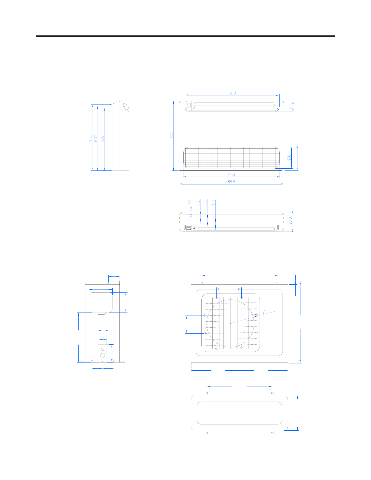
Model: HCFU-14CL03/R1 HCFU-18CL03/R1 Indoor unit
Model: HCFU-14CL03/R1 HCFU-18CL03/R1 Outdoor unit
6
5
5
240
2
0
0
9
480
30
265
220
200
580
288
810
680
75
65
150
100 100
110
190
170
400
4 NET DIMENSIONS OF INDOOR AND OUTDOOR UNIT
NET DIMENSIONS OF INDOOR AND OUTDOOR UNIT
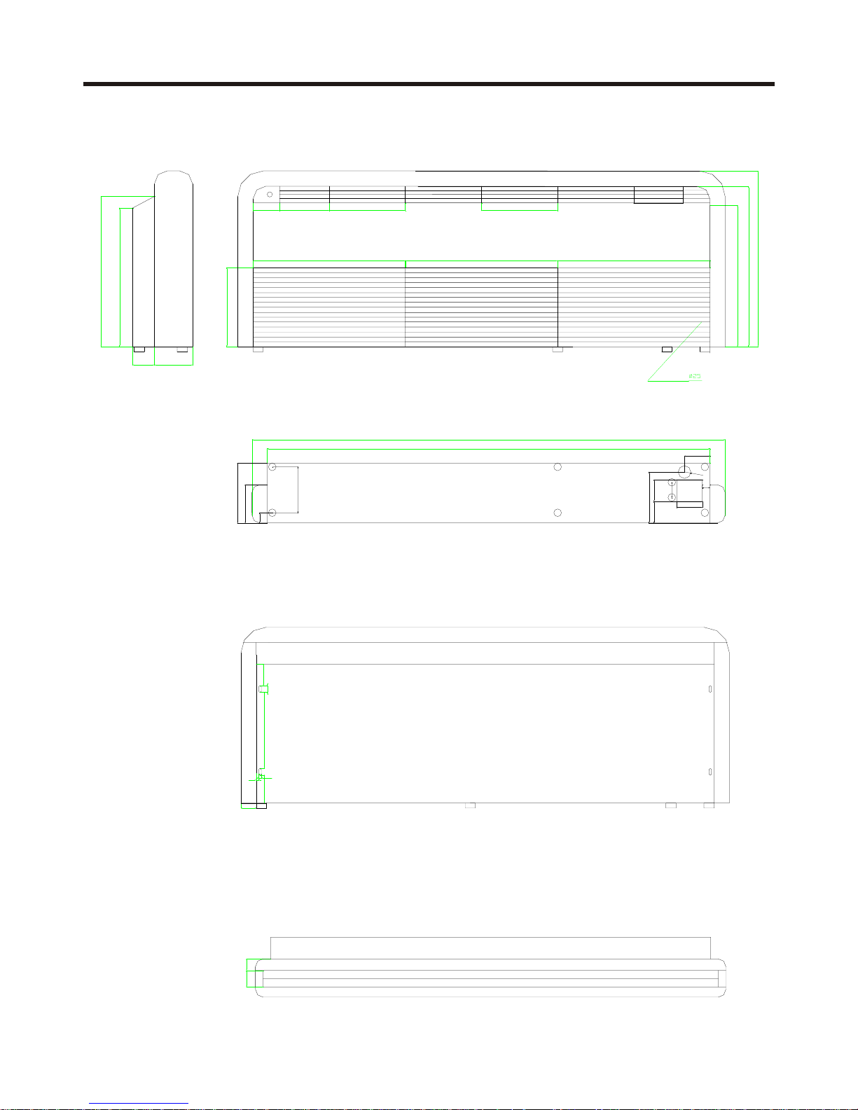
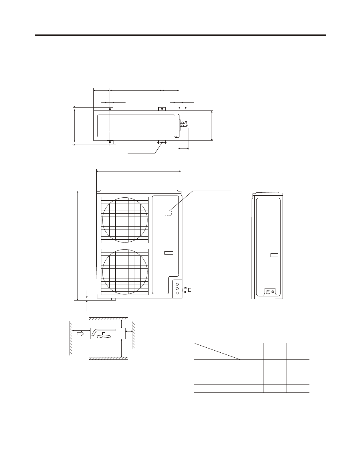
Model: HCFU-24CL03/R1 HCFU-28CM03/R1 Indoor unit
110
180
60
85
100
30
555
630
690
105 195
300
600 600
310.63
85
25
300
10 10
545
590
85 150
60
1200
150
235
1320
40
195
100
85
45
65
R15
drainage pipe
NET DIMENSIONS OF INDOOR AND OUTDOOR UNIT
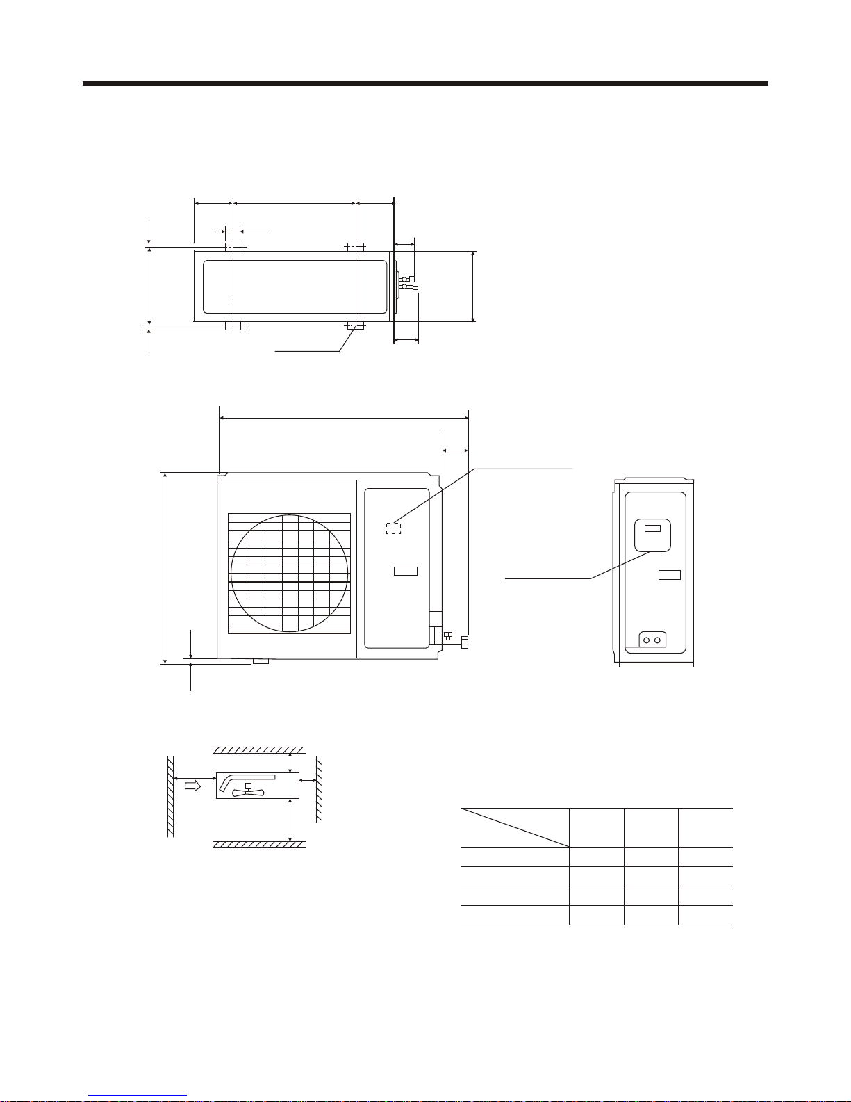
Note (1) Fix the parts with screws
(2)Don't intake the strong wind directly
to the outlet air-flow hole.
(3)A one meter distance should be
kept from the unit top
(4)Don't block the surroudings of the unit with sundries.
Installation Servicing Space(at Least)
Unit:mm
Installation
I
300
100
0
0
150
0
500
100
0
II III
Dimension
L1
Leave space Leave space
Leave space
L2
L3
L4
185 185
55
70
70
Screw Hole
(M10)
580
Power Wiring Terminal
Power Wiring
Distribution Hole
L1
L2
L3
L4
Back Air-flow Hole
Back Airflow Hole
Outlet Air-flow Hole
Repairing Space
70
1024
1818
340
380
840
25
Model: HCFU-24CL03/R1 HCFU-28CM03/R1 Outdoor unit
NET DIMENSIONS OF INDOOR AND OUTDOOR UNIT
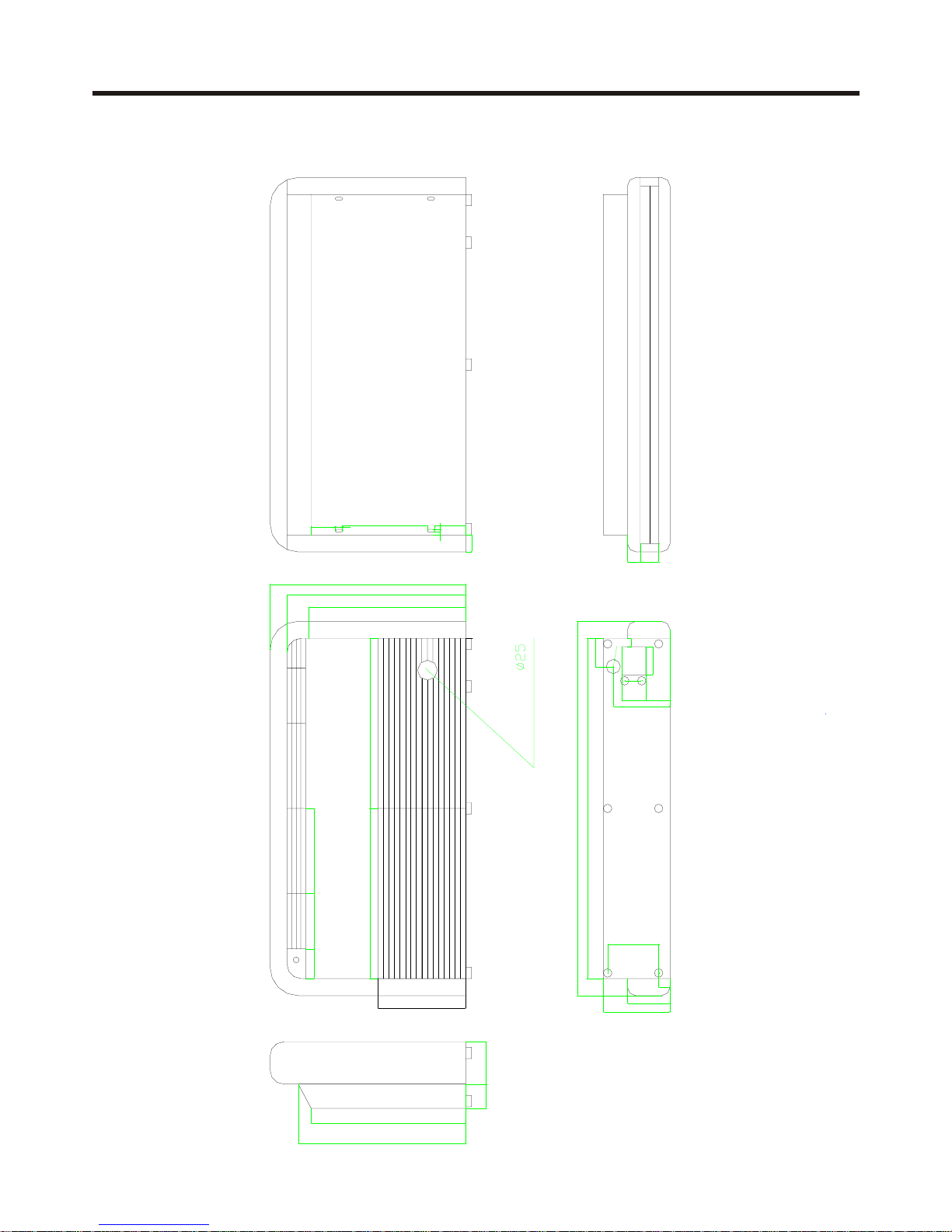
Model: HCFU-36CM03/R1 HCFU-42CM03/R1 Indoor unit
R15
85
100
195
1920
1800
600
690
630
100
85
310
590
545
40
235
150
180
85 150
60
195
600
105
600
300300
555
30
110
60
85
300
10
10
25
65
45
drainage pipe
NET DIMENSIONS OF INDOOR AND OUTDOOR UNIT
185 185
30
52
88
Screw Hole
(M10)
580
950
Power wiring Terminal
70
1818
340
380
1250
25
Note : (1). Fix the parts with screws
(2).Don't intake the strong wind directly
to the outlet air-flow hole.
(3).A one meter distance should be
kept from the unit top
(4).Don't block the surroundings of the unit with sundries
Installation Servicing Space(at Least)
Unit:mm
Installation
I
300
100
0
0
150
0
500
100
0
II III
Dimension
L1
Leave space Leave space
Leave space
L2
L3
L4
L1
L2
L3
L4
Back Air-flow Hole
Back Airflow Hole
Outlet Air-flow Hole
Repairing Space
Model: HCFU-36CM03/R1 HCFU-42CM03/R1 Outdoor unit
NET DIMENSIONS OF INDOOR AND OUTDOOR UNIT
(1) If possible, do not install the unit where it will be
exposed to direct sunlight.(If necessary, install a
blind that does not interfere with the air flow.)
(2) Install the outdoor unit in a place where it will be
free from being dirty or getting wet by rain as much
as possible.
(3) Install the unit where connection to the indoor unit
is easy.
(4) During heating operation, drain water flows from
the outdoor unit. Therefore, install the outdoor unit
in a place where the drain water flow will not be
obstructed.(Reverse cycle model only)
(5) Do not place animals and plants in the path of the
warm air.
(6) Take the weight of the air conditioner into account
and select a place where noise and vibration are
small.
(7) Select a place where the warm air and noise from
the air conditioner do not disturb neighbors.
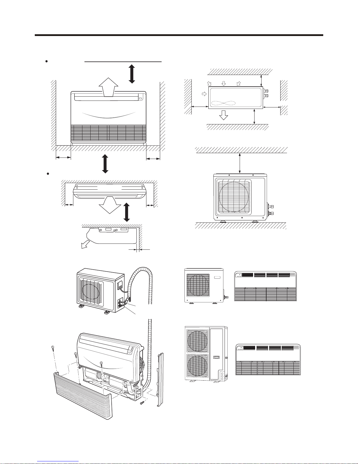
(8) Provide the space shown in Fig.2 so that the air
flow is not blocked. Also for efficient operation, leave
open three of the four directions front, rear, and both
sides.
For authorized service personnel only
SELECTING THE MOUNTING POSITION
2. OUTDOOR UNIT
Decide the mounting position with the customer
as follows:
1. INDOOR UNIT
(1) Install the indoor unit level on a strong wall, floor, ceiling
which is not subject to vibration.
(2) The inlet and outlet ports should not be obstructed: the
air should be able to blow all over the room.
(3) Install the unit near an electric outlet or special branch
circuit.
(4) Do not install the unit where it will be exposed to direct
sunlight.
(5) Install the unit where connection to the outdoor unit is
easy.
(6) Install the unit where the drain pipe can be easily installed.
(7) Take servicing, etc. into consideration and leave the
spaces shown in Fig.1. Also install the unit where the filter
can be removed.
NOTE: The appearance may be different from models.
(1) Install the unit where it will not be tilted by more than 5•
(2) When installing the outdoor unit where it may be
exposed to the strong wind, fasten it securely.
Install at a place that can withstand the weight of the
indoor and outdoor units and install positively so that
the units will not topple or fall.
CAUTION
(1)Do not install where there is the danger of com bustible gas leakage.
(2) Do not install near heat sources.
(3) If children under 10 years old may approach the
unit, take preventive measures so that they can not reach the unit.
L2
L3
L1
500
(Servicing
space)
Air outlet
Air inlet
Air
inlet
Series
24,28 36,42
Case
Distance
L1
L2
L3
open open
open open
500
500
300 300
open open
0 0
100 150 100 150 150300
I II III I II III
Be careful not to scratch the room air conditioner when handing it.
After installation, explain correct operation to the customer, according to the operating manual.
Let the customer keep this installation manual because it will be used when the room air conditioner is serviced
or moved.
WARNING
(1) For the room air conditioner to operate satisfactorily, install it as outlined in this installation manual.
(2) Connect the indoor unit and outdoor unit with the room air conditioner piping and cords available from our
standard parts. This installation manual describes for the correct connections so that the installation set
available from our standard parts should be used.
(3) Installation work must be performed in accordance with national wiring standards by authorized personnel only.
(4) Never cut the power cord, lengthen or shorten the cord, or change the plug.
(5) Also, do not use an extension cord.
(6) Plug in the power cord plug firmly. If the receptacle is loose, repair it before using the room air conditioner.
(7) Do not turn on the power until all installation work is done.
WARNING
WARNING
5 INSTALLATION INSTRUCTIONS
INSTALLATION INSTRUCTIONS
Floor console
Fig. 1
15.88mm dia.
2 cm
or more
Ceiling
Indoor unit
30 cm
or more
30 cm
or more
Left
Right
30 cm
or more
30 cm
or more
1.5m
1.5m
1.5m
Left
Right
may be different
For series24, 28
For series 36,42
Note: For series 36, 42 no floor console type, the function
below about floor console is invalid to the series.
30 cm
or more
60 cm
or more
40 cm or more
30 cm
or more
Fig. 2
For series 14,18
60 cm
or more
Under ceiling
6.35mm dia
Outdoor unit
Indoor unit
For series 14,18
INSTALLATION INSTRUCTIONS
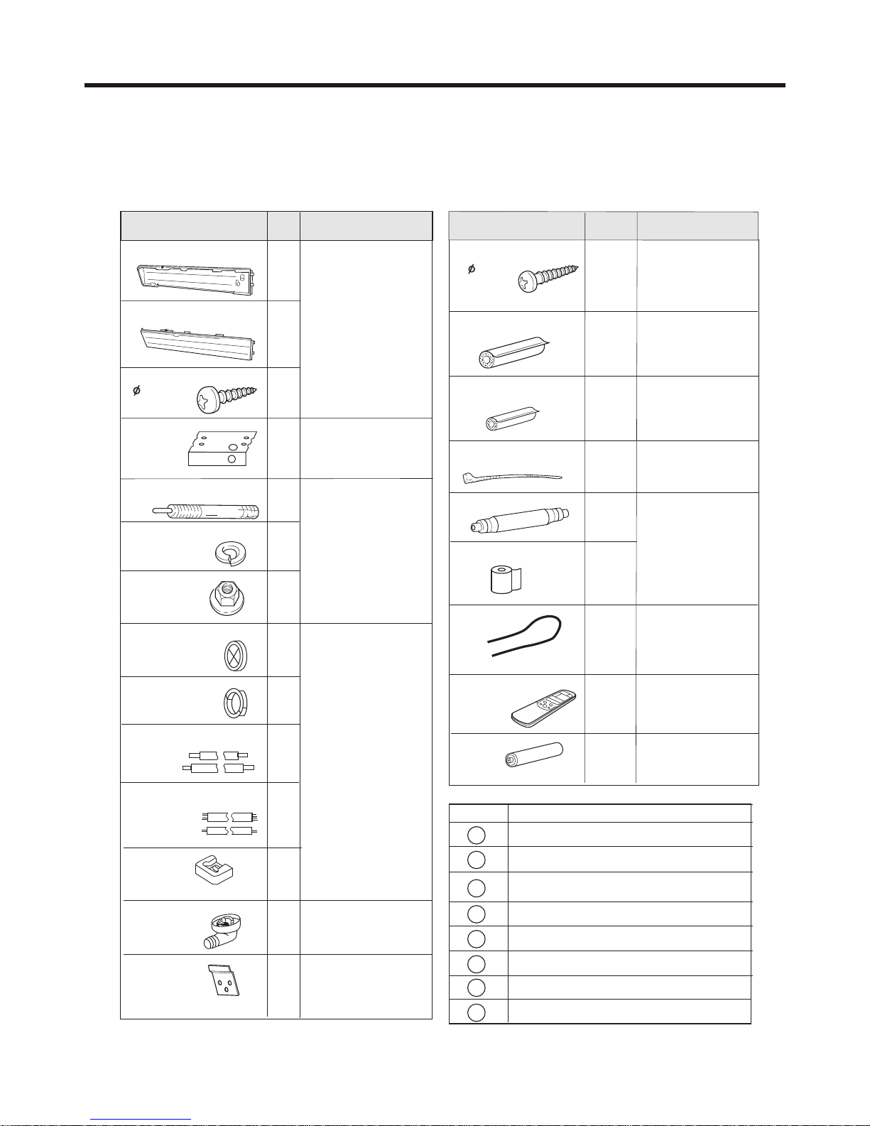
Mark Parts name
Adhesive tape
Saddle (L.S) with screws
Connecting electric cable
for indoor and outdoor
Drain hose
Heat insulation material
Piping hole cover
Putty
Plastic clamp
Optional parts
A
B
C
D
E
F
G
H
STANDARD PARTS
The following installation parts are furnished.
Use them as required.
ACCESSORIES
Name and shape
Q'ty
Application
6
For fixing the wall
bracket.
For series 24,28,36,42
no this part.
Tapping screw
( 4x20)
Coupler heat insulator(large)
1
For indoor side pipe
joint (Large pipe)
Coupler heat insulator(small)
1
For indoor side pipe
joint (Small pipe)
Nylon fastener
1
For fixing the drain
hose
Drain hose
Non-adhesive tape
1
1
VT wire
1
For fixing the drain
hose L 280mm
For series 24,28,36,42
VT wire is not available
Remote
controller
Battery
1
2
Use for air conditioner
operation
For remote controller
unit
Name and shape
Q'ty
Application
1
For series 24,28, 36,42
the two cover plate are
not available
Cover plate (left)
Cover plate (right)
Installation
template
Anchor bolt
Spring washer
Special nut
Pipe hole cover
Wall hole cover
Main pipes
Connecting cables
1
2
1
4
4
4
1
1
1
1
For positioning the
indoor unit
For under ceiling type.
For suspending the
indoor unit from ceiling
4
Tapping screw
( 4x10)
Cushion
Drain-elbow
1
Only for the heat pump
type
Wall bracket
2
For suspending the indoor
unit on the wall.For series
24,28,36,42 no this part.
INSTALLATION INSTRUCTIONS
INSTALLATION PROCEDURE
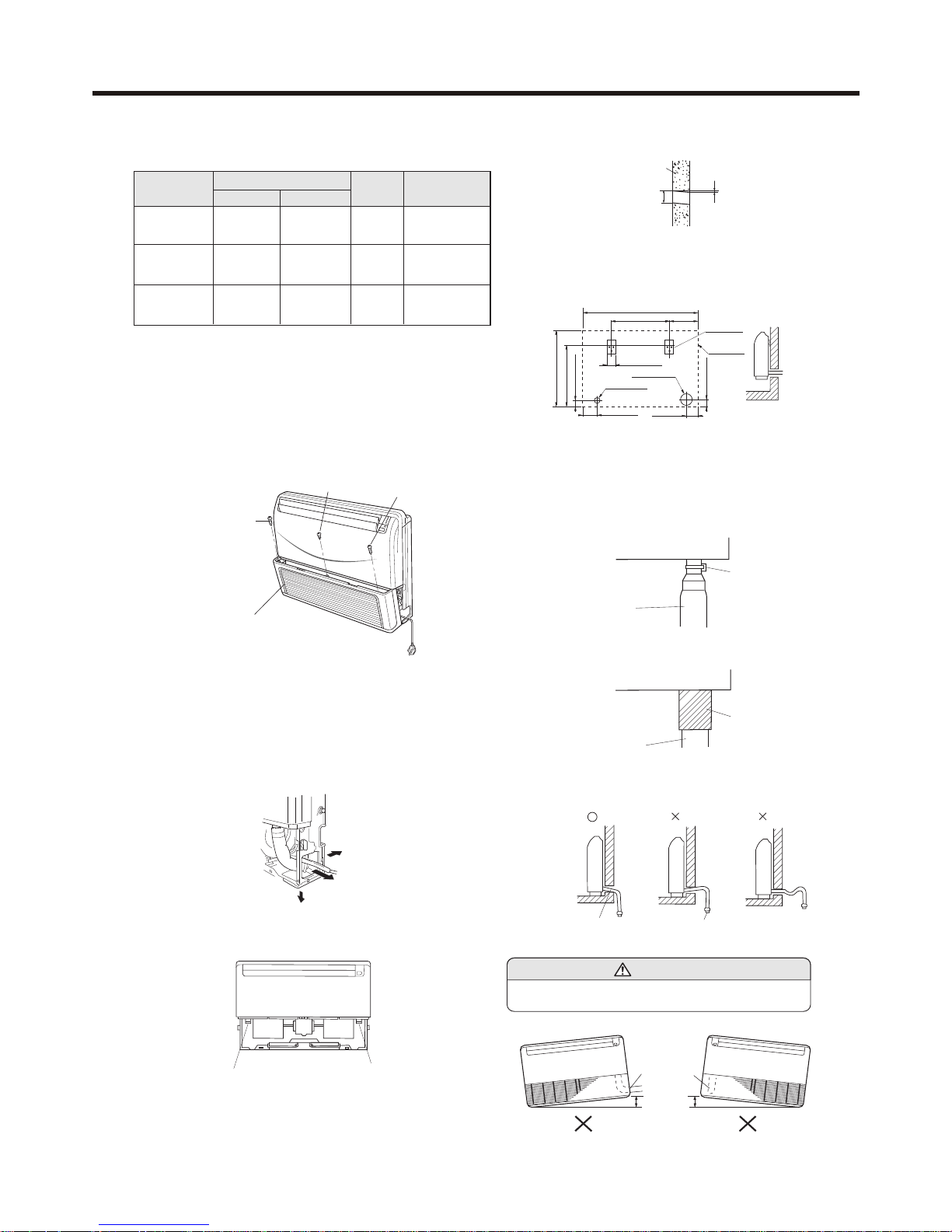
PREPARING INDOOR UNIT
INSTALLATION
1. REMOVE THE INTAKE GRILL
Install the room air conditioner as follows:
Open the intake grill and remove the three or four or six screws.
(Fig. 3)
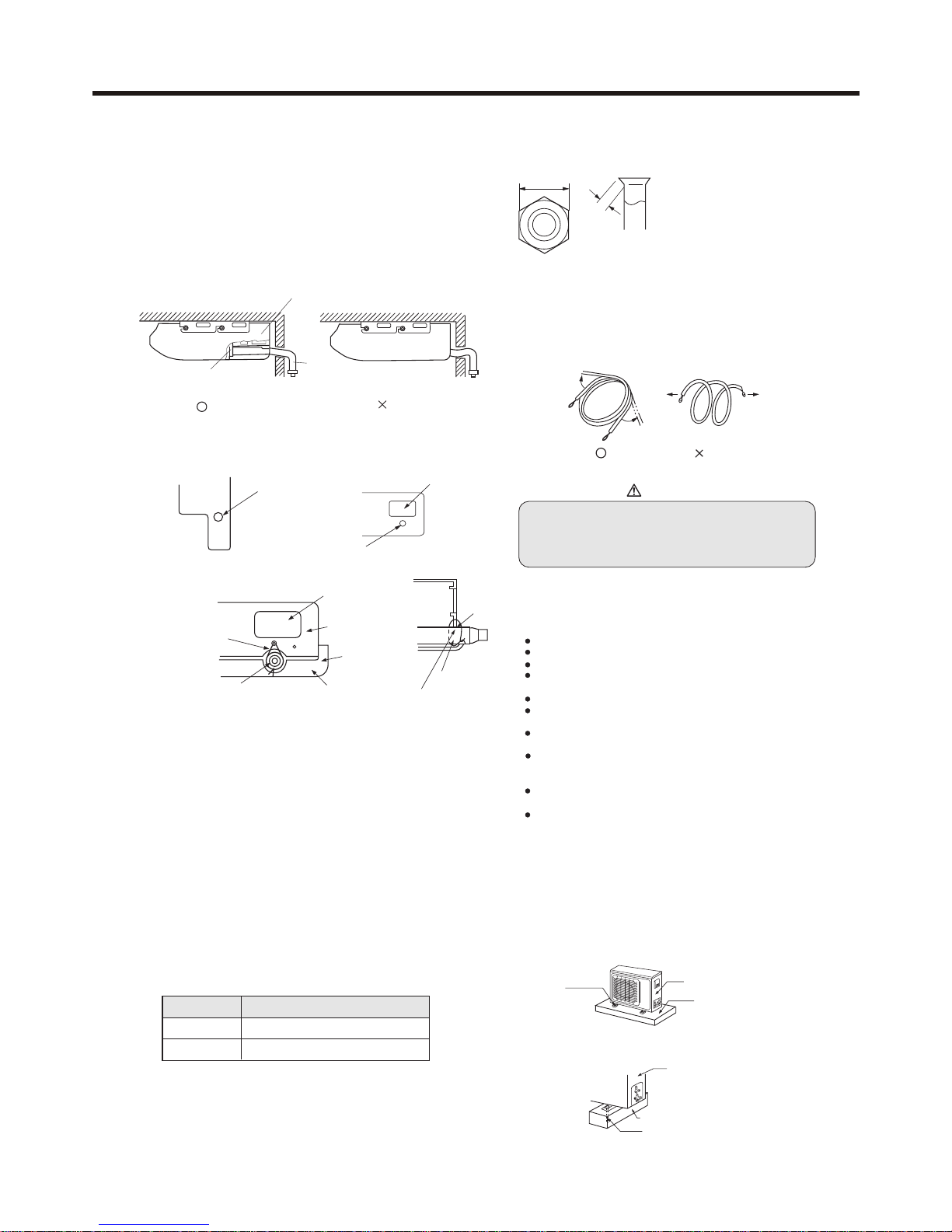
When the directions are selected, drill a 7 cm dia. hole on the wall so
that the hole is tilted downward toward the outdoor for smooth water
flow. When the pipe is led out from the rear, make a hole in Fig.6, at
the position shown.
(Fig. 5)
Drain hose (Left side) Drain hose (Right side)
CONNECTION PIPE REQUIREMENT
Table 1
Series
Diameter
Liquid side Gas side
Maximum
length
Maximum height
(between indoor
and outdoor)
14,18
6.35 mm
9.52 mm
15.88 mm
19.05mm
15 m
50 m
5 m
15 m
9.52 mm 15.88 mm
30 m
15 m
24,28
36,42
Remark: The main unit can be wired before the indoor unit is
installed. Select the most appropriate installation order.
For series 24,28,36,42 not the power plug, but 3-core connecting cable.
A. FLOOR CONSOLE TYPE (For series 36,42 no this type )
1. DRILLING FOR PIPING
Select piping and drain directions.(Fig.4) (For series 14,18)
The piping and drain can be made in three directions as shown
below.For series 24,28,36,42 can be made rear and down two
directions.
The drain hose can be connected to either the left or right side.(Fig.5)
For series 24,28,36,42 only right side.
(Fig. 4)
rear
right
down
Select whether the drain hose will be connected to the
left or right side.(for series 24,28,36,42 only the right side).(Fig.5)
Insert the drain hose into the drain pan, then secure the
drain hose with a nylon fastener. (Fig.8)
Wall
7cm
6mm
Indoor unit outdoor unit
2. INSTALLING DRAIN HOSE
(Fig. 6)
For series 14,18 when installing set to wall, install the
accessory wall bracket at the position shown in Fig.7,
and mount the set to it.
(Fig. 7)
INSTALL THE DRAIN HOSE
Wrap the insulation (drain hose) around the drain hose
connection.(Fig.9)
Drain pan
Drain hose
Nylon fastener
(Fig. 8)
(Fig. 9)
Drain pan
Drain hose
Insulation
(Drain hose)
Wall bracket
Side of set
Arrange the drain hose
lower than this portion.
Fig. 10
Be sure to arrange the drain hose correctly so that it is
leveled lower than the drain hose connecting port of the
indoor unit.
OK NO NO
Drain hose
A A
CAUTION
Do not install the unit drain hose side is too high. Height A
should be less than 5 mm.(Fig.11)
Fig. 11
Drain hose
Fig. 3
Machine screw
Tapping screw
Tapping screw
Intake grill
65.5cm
99cm
50cm
24.5cm
6.5cm
12.5cm 10cm
6.5cm
53cm
4.5cm
7cm hole
3.5cm hole
INSTALLATION INSTRUCTIONS
Installation
template
Wall
Ceilling
Drilling position
for piping
Drilling position
for anchor bolt
200mm
900mm
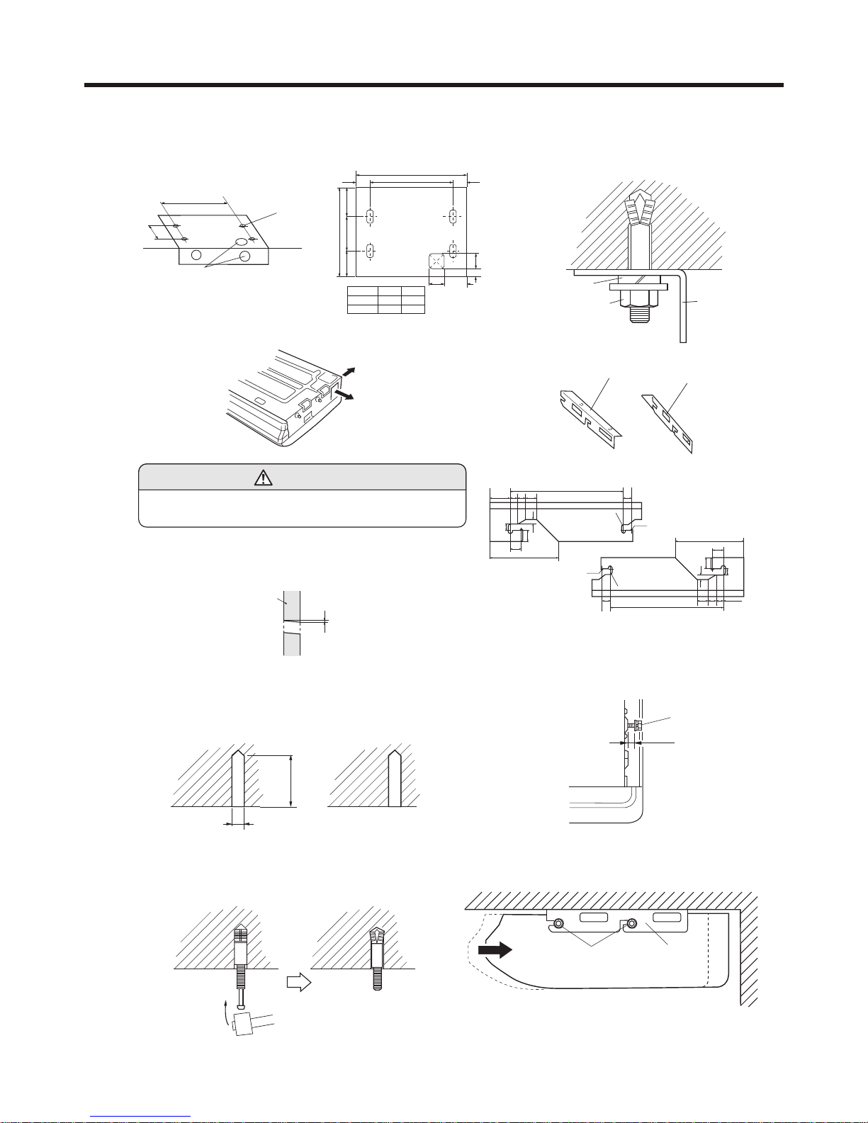
Select piping and drain directions. For series 24,28,36,42 only rear side(Fig.13)
B. UNDER CEILING TYPE
Using the installation template, drill holes for piping and anchor bolts(for
holes).(Fig.12)
Fig. 12
For series 14,18
1. DRILLING FOR PIPING
Fig. 13
CAUTION
60 to 70mm
12.7mm
Fig. 16
Insert the anchor bolts into the drilled holes, and drive the pins
completely into the anchor bolts with a hammer. (Fig. 16)
2. DRILLING HOLES FOR ANCHOR BOLTS AND
INSTALLING THE ANCHOR BOLTS
Install the drain hose at the rear; it should not be installed
on the top or right side.
When the directions are selected, drill 80mm and 50mm or 150mm
dia. hole on the wall so that the hole is tilted downward toward the
outdoor for smooth water flow.
3. INSTALLING BRACKETS
Fig. 17
Install the brackets with nuts, washers and spring
washers.(Fig. 17)
Spring washer
Special nut
Bracket
4. INSTALLING INDOOR UNIT
68
16 21 28
381
232
26.5
26.5
2-R2.5
10
18
7.5
4-R5
For series 24,28,36,42
Bracket (Right)
Bracket (Left)
For series 14,18
68
16
21
28
381
232
26.5
26.5
2-R2.5
10
18
7.5
4-R5
Reset the hex bolts as shown in Fig.18.
Hex bolt
8 to 13mm
Indoor unit
Fig. 18
Apply the indoor unit to the brackets.(Fig.19)
Now, securely tighten the hex bolts in both sides.
Fig. 19
Bolt
Bracket
Indoor unit
A
B
40 40
100mm
720mm
87.5mm
147mm
326mm
247mm
85
53
series A B
24,28
36,42 1920 1840
12401320
Rear (Install the drain hose
in the direction.)
Right
Wall
6mm
Fig. 15
With a concrete drill, drill four 12.7 mm dia. Holes.(Fig.15)
INSTALLATION INSTRUCTIONS
1. FLARE PROCESSING
(1) Cut the connection pipe with pipe cutters so that the pipe is
not deformed.
(2) Holding the pipe downward so that cuttings cannot enter the
pipe, remove the burrs.
(3) Remove the flare nut from the indoor unit pipe and outdoor
unit and assemble as shown in(Table1) and insert the flare
nut onto the pipe, and flare with a flaring tool.
(4) Check if the flared part "L" (Fig.22)is spread uniformly and
that there are no cracks.
For series 24,28,36,42
Fig. 21
When drain hose is arranged backward.Secure the drain hose with
the VT wire. (Fig. 21)
5. INSTALL THE DRAIN HOSE
Select whether the drain hose will be connected to the left or right
side.(Fig.5)
Insert the drain hose into the drain pan, then secure the drain hose
with a nylon fastener.(Fig.8)
Wrap the insulation (drain hose)around the drain hose connection.
(Fig.9)
Be sure to arrange the drain hose correctly so that it is leveled lower
than the drain hose connecting port of the indoor unit.(Fig.20)
CONNECTING THE PIPING
OUTDOOR UNIT INSTALLATION
Fig. 22
2. BENDING PIPES
Fig. 23
The pipes are shaped by your hands. Be careful not to
collapse them.
L
Width across flats
L dimension
Liquid pipe
1.6 to 1.8mm(6.35mm dia)
Gas pipe
2.2 to 2.4mm(15.88mm dia)
Gas pipe
3.4 to 2.6mm(19.05mm)
Liquid pipe
1.8 to 2.0mm(9.52mm)
Table 1
Pipe Flare nut
Small pipe
Large pipe
Small (width across flats 22mm)
Large (width across flats 24mm)
WARNING
BE SURE TO READ THESE INSTRUCTIONS. CAREFULLY BEFORE
BEGINNING INSTALLATION. FAILURE TO FOLLOW THESE
INSTRUCTIONS COULD CAUSE SERIOUS INJURY OR DEATH,
EQUIPMENT MALFUNCTION AND /OR PROPERTY DAMAGE. BE
SURE TO READ INSTALLATION MANUAL FOR INDOOR UNIT WITH
THIS MANUAL.
1. Selection of the place of installation
Select the place of installation satisfying the following
conditions and, at the same time, obtain consent from the
client or user.
Place where air circulates.
Place free from heat radiation from other heat sources.
Place where drain water may be discharged.
Place where noise and hot air may not disturb the
neighbors.
Place where there is not heavy snowfall in winter.
Place where obstacles do not exist near the inlet air
port and outlet air port.
Place where the outlet port may not be exposed to a
strong wind.
Place surrounded at four sides are not suitable for
installation.
A 1m or more of overhead space is needed for the unit.
Mount guide-louvers to place where short-circuit is a
possibllity.
When installing several units, secure sufficient suction
space to avoid short circuiting.
Fig. 20
Remove the hole cover.
OK
Arrange the drain hose
lower than this portion
Drain hose
NO
VT wire hole
Drain hose
Piping hole
VT wire
Drain hose
For series 24,28,36,42
no this part
Piping hole
Base (Bottom)
Intake grill
VT wire hole
Pass the drain hose through here
Cut the grill
OK
NO
Extend the pipe by unwinding it
Fix the unit in a proper way according to the condition of
a place where it is installed by referring to the following.
(1) Installation
2. Installation of outdoor unit
For series 14,18
Fig. 25
(a) Concrete foundation(Fig. 25)
For series 14,18
Anchor bolt
(b) Foundation anchor
Unit
Concrete foundation
Anchor bolt
Concrete foundation
Unit
INSTALLATION INSTRUCTIONS
Note (1)
Place the concrete
foundation
deep enough.
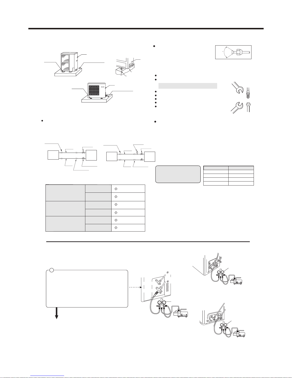
Connecting method
Apply refrigerant oil at half union as large and flare nut.
To bend a pipe, give the roundness as possible not to
crush the pipe.
When connecting pipe, hold the pipe centre to centre
then screw nut on by hand, refer to Fig.
Be careful not to let foreign matters, such as sands
enter the pipe.
(4) Piping connection (Fig.26)
Note (1)
Give enough room for the concrete
foundation to fix anchor bolts.
For series 24,28
To fix by bolts
Concrete foundation
(a) Concrete foundation
For series 36,42
Fig. 25
(b) Foundation anchor
Outdoor
unit
For series 14,18
For series 24,28,36, 42
(1) Outline of piping
3. Refrigerant piping
Service
Flare connection
Check joint
Gas pipe
Liquid
pipe
Flare connection
Indoor
unit
Outdoor
unit
3-way valve
Flare connection
Gas pipe
Liquid
pipe
Flare connection
Indoor
unit
2-way valve
(2) Piping size
Install the removed flare nuts
to the pipes to be connected,
then flare the pipes.
90 •0.5
One way piping length: Less than 15 mm
Vertical height difference: Less than 5 m
(3) Limitations for one way piping length and vertical
height difference.
Precautions for refrigerant piping
(Fig. 26)
Do not twist or crush piping.
Be sure that no dust is mixed in piping.
Bend piping with as wide angle as possible.
Keep insulating both gas and liquid piping.
Check flare-connected area for gas leakage.
Forced fastening without
centering may damage the
threads and cause a gas
leakage.
(5) Purging mehtod ( the refrigerant is R407C )
Install the unit so that the angle of inclination must be less than
3 degrees.
Series 24,28
Gas pipe
15.88x1.0mm
Liquid pipe
Gas pipe
9.52x0.8mm
15.88x1.0mm
Series 36,42
Liquid pipe
Gas pipe
9.52x0.8mm
19.05x1.0mm
Liquid pipe
6.35x0.8mm
Series 14,18
Pipe dia Fastening torque
Liquid pipe 6.35mm
Gas pipe 15.88mm
Liquid pipe 9.52mm
Gas pipe 19.05mm
18N.m
60N.m
40N.m
110N.m
For series 24,28
1
Detach the service port's cap of 3-way valve, the
valve rod's cap for 2-way valve and 3-way's, connect
the service port into the projection of charge hose
(low) for gaugemanifold. Then connect the projection
of charge hose (center) for gaugemanifold into
vacuum pump.
To use vacuum pump
Vacuum pump
Gaugemanifold
2-way valve
3-way valve
Liquid Side
6.35mm (1/4")
Gas Side
15.88mm (5/8")
For series 14,18
For series 36,42
Gaugemanifold
Vacuum pump
2-way valve
3-way valve
Vacuum pump
3-way valve
2-way valve
Gaugemanifold
Anchor bolt
Unit
Unit
Concrete
foundation
Anchor bolt
Unit
Anchor bolt
Concrete foundation
INSTALLATION INSTRUCTIONS
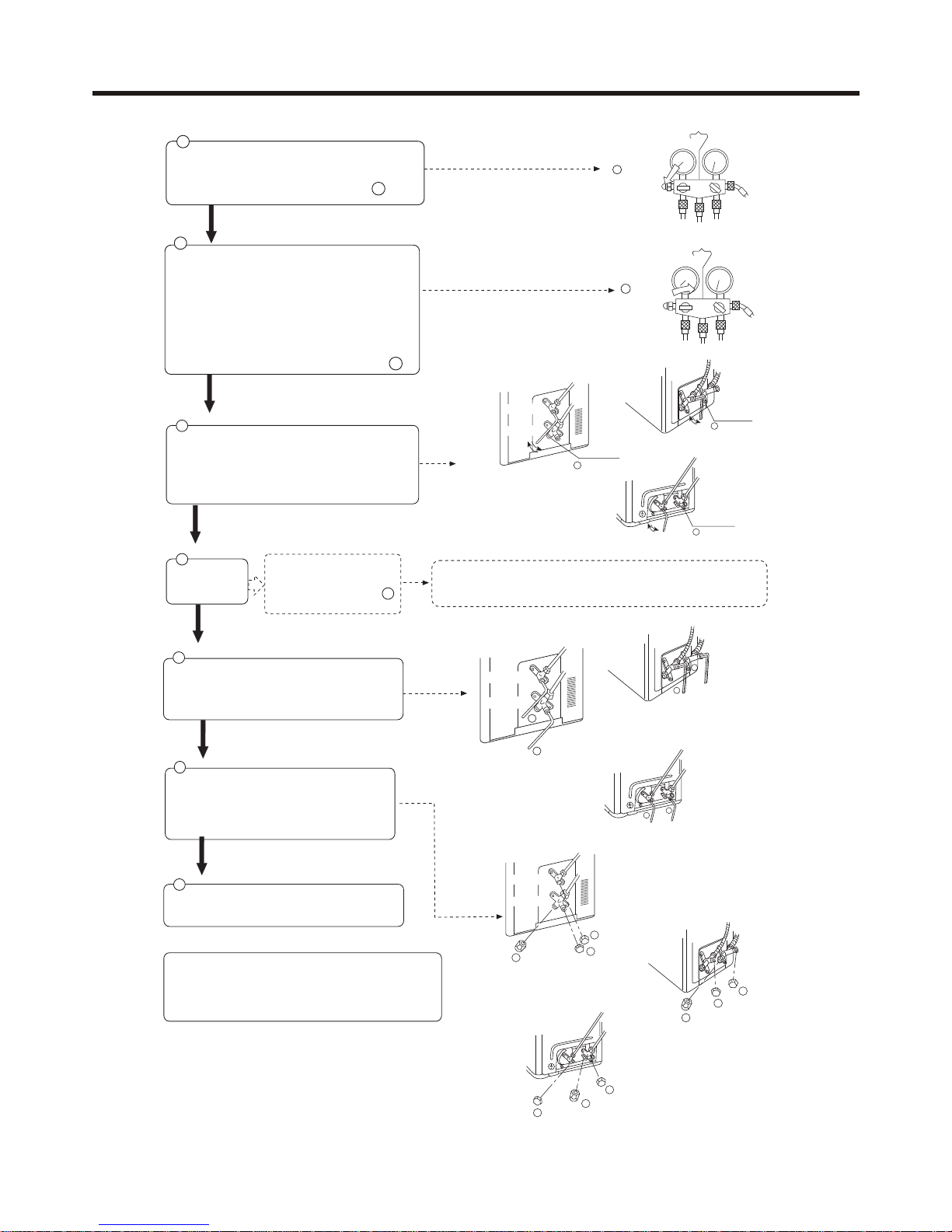
Detach the charge hose from the service port, open
2-way valve and 3-way. Turn the valve rod
anticlockwise until hitting lightly.
6
If it does not stop gas leakage, discharge whole refrigerants from the serice port.
After flaring work again and vacuumize, fill up prescribed refrigerant from the gas
cylinder.
In case of gas leakage, tighten
parts of pipe connection. If
leakage stops, then proceed
steps.
6
No gas leakage?
5
4
Open the valve rod for the 2-way valve to and angle of
anticlockwise 90 degree.
After 6 seconds later, close the 2-way valve and male
the inspection of gas leakage.
CAUTION:
If the refrigerant of the air conditioner leaks, it is necessary to make
all the refrigerant out, then charge the liquid refrigerant into air
conditioner according to the amount marked on the name plate.
To prevent the gas leakage, turn the service port's
cap, the valve rod'd cap for 2-way valve and 3-way's
a lottle more than the point where the torque increases
suddenly.
7
8
After attaching the each caps, check the gas leakage
around the caps.
2
Open
2
Open the handle at low in gaugemanifold, operate
vacuum pump. If the scale-moves of gause (low)
reach vacuum condition in a moment, check 1 again.
3
Close
Vacuumize for over 15min. And check the level gauge
which should read -0.1 MPa (-76 cm Hg) at low
pressure side. After the completion of vacuumizing,
close the handle 'Lo' in gaugemanifold and stop the
operation of the vacuum pump.
Check the condition of the scale and hold it for 1-2min.
If the scale-moves back in spite of tightening, make
flaring work again, the return to the beginning of 3 .
For series 24,28
For series 36,42
3-way valve
2-way valve
Open
90•
Service port
90•
4
90• for 6 sec.
For series 14,18
2-way valve
3-way valve
Open
90•
90•
Service port
4
90• for 6 sec.
2-way valve
3-way valve
90•
Service port
90•
4
90• for 6 sec.
Open
3
For series 24,28
3-way valve
2-way valve
6
6
For series 36,42
Liquid pipe 9.52mm
Gas pipe 19.05mm
2-way valve
3-way valve
6
6
6
6
2-way valve
3-way valve
For series 14,18
Service port cap
7
3-way valve
2-way valve
7
Valve rod cap
Valve rod cap
7
For series 24,28
2-way valve
3-way valve
7
Valve rod cap
Valve rod cap
7
Service port cap
7
For series 14,18
3-way valve
2-way valve
7
Valve rod cap
Valve rod cap
7
Service port cap
7
For series 36,42
INSTALLATION INSTRUCTIONS
GAS LEAKAGE INSPECTION
After connecting the piping, check the joints for gas leakage with gas leakage detector.
CAUTION
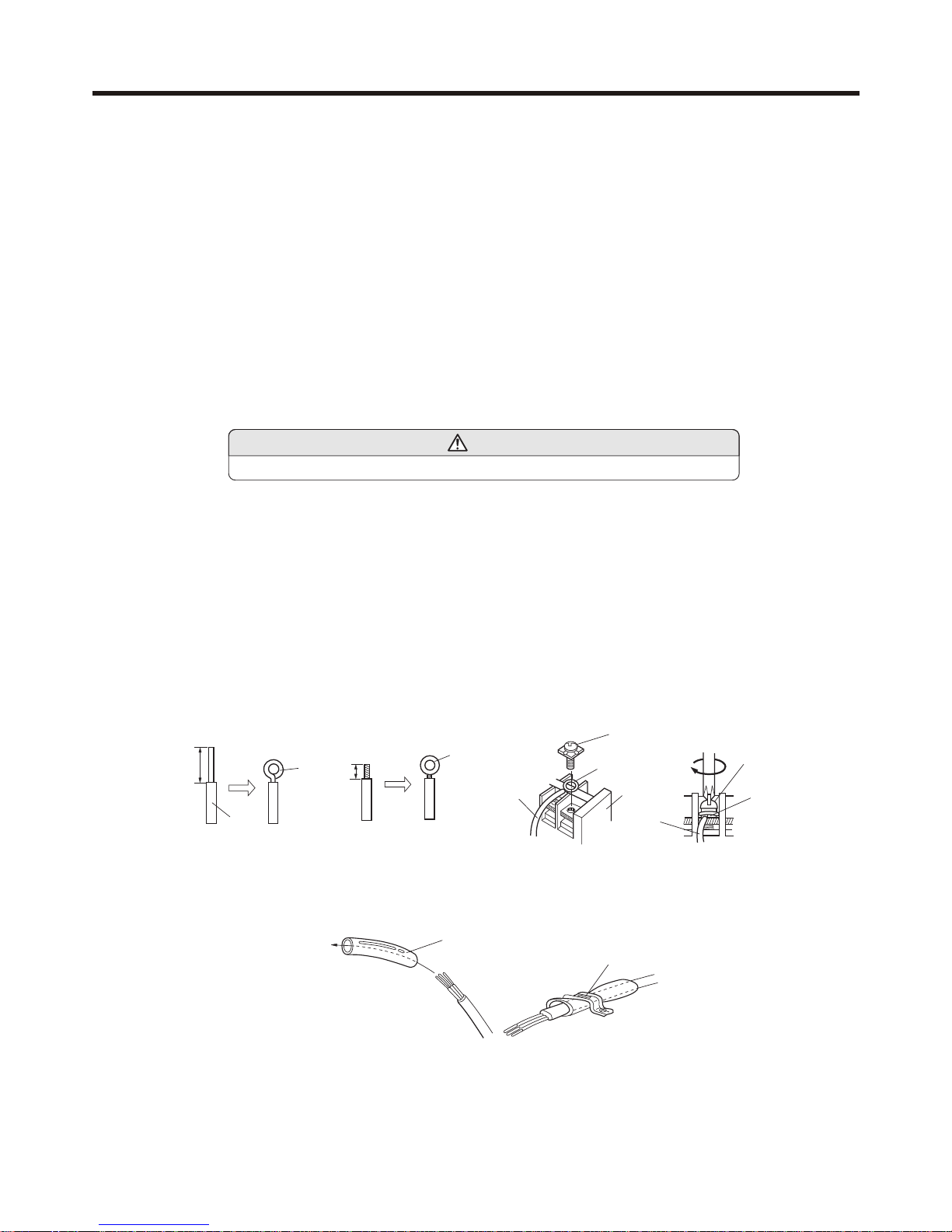
HOW TO CONNECT WIRING TO THE TERMINALS
A. For solid core wiring (or F-cable)(Fig.28A)
(1) Cut the wire with a wire cutter or wire-cutting pliers, then strip the insulation to about 25mm of the exposed solid wire.
(2) Using a screwdriver, remove the terminal screw(s) on the terminal board.
(3) Using pliers, bend the solid wire to form a loop suitable for the terminal screw.
(4) Shape the loop wire properly, place it on the terminal board and tighten securely with the terminal screw using a screw driver.
B. For strand wiring(Fig.28B)
(1) Cut the wire with a wire cutter or wire-cutting pliers, then strip the insulation to about 10mm of the exposed strand wiring.
(2) Using a screwdriver, remove the terminal screw(s)on the terminal board.
(3) Using a round terminal fastener or pliers, securely clamp a round terminal to each stripped wire end.
(4) Position the round terminal wire, and replace and tighten the terminal screw using a screw driver.
Fig. 28
Screw with
special washer
Round
terminal
Wire
Terminal
board
Screw with
special washer
Round
terminal
Wire
A. Solid wire
Insulation
Strip 25mm
Loop
B. Strand wire
Strip 10mm
Round
terminal
After passing the connection cord and power cable through the insulation tube, fasten it with the cord clamp, as shown in Fig.29
HOW TO FIXED CONNECTION CORD AND POWER CABLE AT THE CORD CLAMP
Fig. 29
Cord clamp
Insulation tube
Use VW-1, 0.5 to 1.0 mm thick, PVC tube as the insulation tube.
If needing to remove the refrigerant gas when installation or repair , please refer to
the following procedures:
1. Cut off the power
2. (After confirming the power is cut off) pull the power cable plug terminals of the low-pressure
pressure-switch out.
3. (After confirming the power cable terminals of the low-pressure pressure-switch is cut off) After
powering on the unit again and switch to COOLING mode,perform refrigerant gas removing
according to the normal refrigerant gas removing procedure.
4. After finishing refrigerant gas removing , cut off the power , then insert the power cable terminals
of the low-pressure pressure-switch properly.
INSTALLATION INSTRUCTIONS
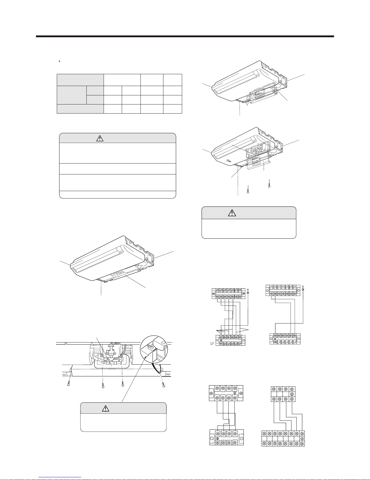
1. INDOOR UNIT SIDE
(1) Remove the electric component box.
INDOOR UNIT SIDE
(2) Pull out the electric component box.
Fig. 32
(3) Remove the electric component box cover.
Fig. 33
(1) Remove the cord clamp.
(2) Process the end of the connection cords to the
dimensions shown in Fig.34.
(3) Connect the end of the connection cord fully into the
terminal block.
(4) Wiring
Fig. 30
Electric component box
CAUTION
Be careful not to pinch the lead wires
between the electric component box
and base.
ELECTRICAL REQUIREMENT
Electric wire size and fuse capacity:
Table 5
ELECTRICAL WIRING
Series
Connection
cord
(mm2)
Fuse capacity(A)
MAX
MIN
14,18 24,28 36,42
3.5 3.5 3.5 3.5
2.5
2.5 2.5 2.0
20 30 30 30
CAUTION
(1) Match the terminal block numbers and connection
cord colors with those of the outdoor unit.
Erroneous wiring may cause burning of the electric
parts.
(2) Connect the connection cords firmly to the terminal
block. Imperfect installation may cause a fire.
(3) Always fasten the outside covering of the connection
cord with the cord clamp.(If the insulator is chafed,
electric leakage may occur.)
(4) Always connect the ground wire.
Fig. 31
Electric component box
Remove the four tapping
screws.
CAUTION
Do not remove the screws. If the screws
are removed, the electric component
box will fall.
(4) Fasten the connection cord with a cord clamp.
(5) Fasten the end of the connection cord with the screw.
(6) For series 24,28,36,42,the power cable and connecting
are self-provided.
Outdoor
unit
Indoor
unit
Outdoor
unit
1 2 3
1
2
3
For series 14,28
For series 36,42
Indoor
unit
Outdoor
unit
1 2 3
1 2 3
N
TSR
Base
Electric component box cover
Remove the three tapping screws.
Fig. 34
For series 14,18
Indoor unit
Outdoor unit
1 2 3 4 5 L N
1
2345
H05RN-F
4G0.75mm
2
H07RN-F
2 2.0mm
2
Electric component box
For series 14,18
Indoor unit
Outdoor unit
H07RN-F
3G 2.0mm
2
1 2 3 4 5
1
2345
L N
Heat model
Cool model
INSTALLATION INSTRUCTIONS
TEST RUNNING
CUSTOMER GUIDANCE
Explain the following to the customer in accordance with the
operating manual:
(1) Starting and stopping method, operation switching, temperature
adjustment, timer, air flow switching, and other remote control
unit operations.
(2) Air filter removal and cleaning, and how to use air louvers.
(3) Give the operating and installation manuals to the customer.
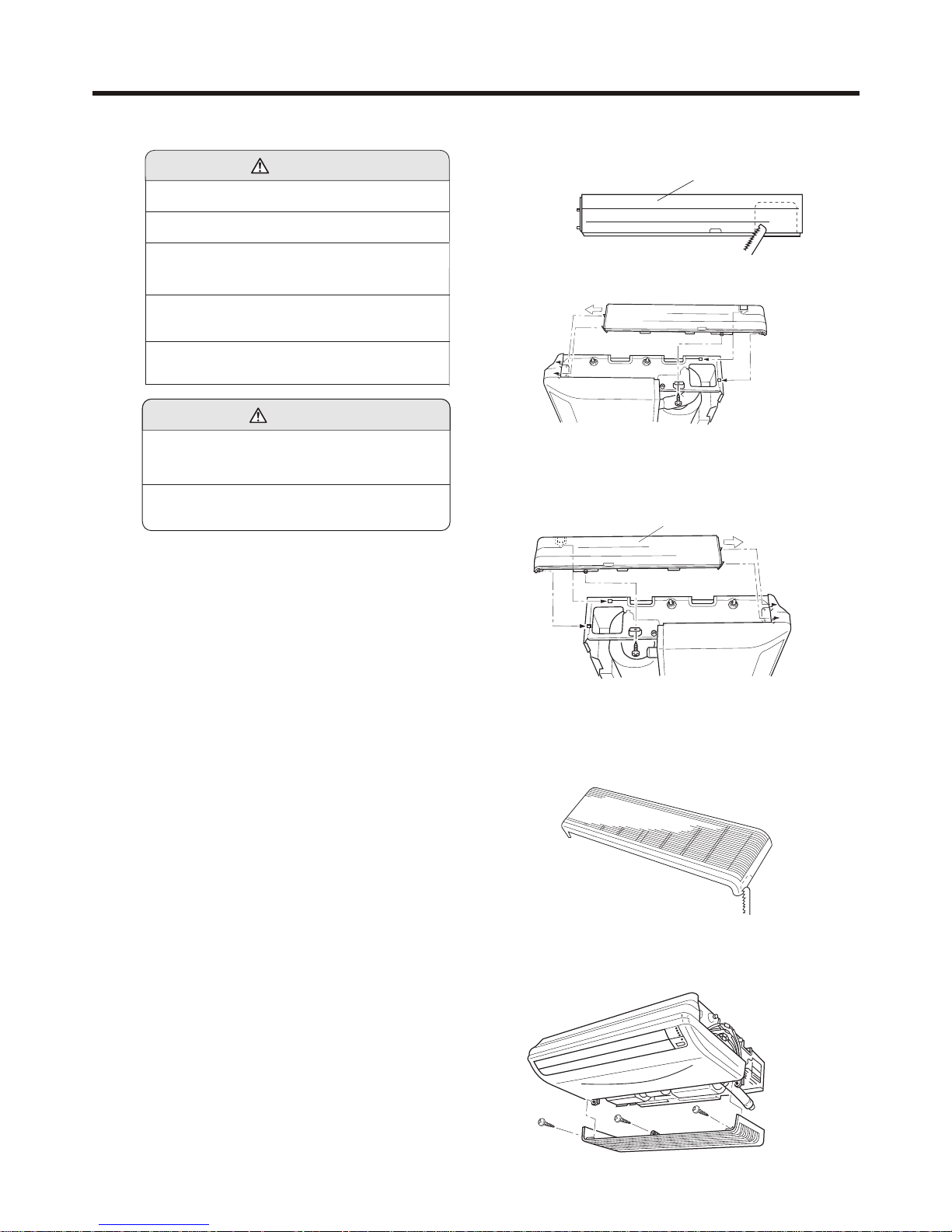
MOUNT THE COVER PLATE AND
THE INTAKE GRILL
Note: The following installing procedure only for series 14,18
1.Mount the cover plate. (Right)
(1) Cut a pipe exit hole in the right plate. This is only when the
pipe exits from the right side.(This operation is not required
when the protrusion is on the top or rear.)
(2) Join the cover plates (right) and mount with screws.
Cover plate (Left)
2. Mount the cover plate.(Left)
(1) Join the cover plate (left) and mount with screws.
Fig. 37
(1) The power source capacity must be the sum of the
room air conditioner current and the current of other
electrical appliances. When the current contracted
capacity is insufficient, change the contracted capacity.
(2) When the voltage is low and the air conditioner is dif ficult to start, contact the power company the voltage
raised.
CAUTION
1. CHECK ITEMS
(1) INDOOR UNIT
(1) Is operation of each button on the remote control unit normal?
(2) Does each lamp light normally?
(3) Do not air flow direction louvers operate normally?
(4) Is the drain normal?
(2) OUTDOOR UNIT
(1) Is there any abnormal noise and vibration during operation?
(2) Will noise, wind, or drain water from the unit disturb the neighbors?
(3) Is there any gas leakage?
(1) Cut the right side of the intake grill. This is only
when the pipe exits from the right side
3. Mount the intake grill.
Fig. 38
(2) Insert the hinges on the bottom of the intake grill into the
holes in the base assembly. Then mount the arms to the
three areas on the top of the intake grill.
Fig. 39
Fig. 35
Cover plate (Right)
Fig. 36
ELECTRICAL WIRING
(1) Always use a special branch circuit and install a special
receptacle to supply power to the room air conditioner.
(2) Use a circuit breaker and receptacle matched to the
capacity of the room air conditioner.
(3) The circuit breaker is installed in the permanent wiring.
Always use a circuit that can trip all the poles of the
wiring and has an isolation distance of at least 3mm
between the contacts of each pole.
WARNING
(4) Perform wiring work in accordance with standards so
that the room air conditioner can be operated safely
and positively.
(5) Install a leakage circuit breaker in accordance with the
related laws and regulations and electric company
standards.
INSTALLATION INSTRUCTIONS
 Loading...