

Haier AC092FEAHA, AC092FEBHA, AC122FEAHA, AC122FEBHA, AC142FEAHA Installation Manual
...
Safety Precautions
Read this ìsafety precautionsî carefully and thoroughly before implementation to ensure proper installation.
These precautions whose marks and contents as the following MUST be complied with for they include
important points concerning safety.
Contents marked with this sign concern personal safety of the user. Improper
operation can cause personal death or injury.
Warning!
Notice!
Contents marked with this sign concern safety of the product and user. Improper
operation can cause personal injury or damage of machine.
Trial run MUST be done after installation of the assembly to ensure no disorders occur. Meanwhile,
explain method of use and trouble-shooting to the user according to the operation manual.
In addition, this installation instruction and operation manuals should be kept by the user.
Warning!
Installation MUST be implemented by authorized organization and professional personnel.
Unauthorized installation may cause water leakage, electric shock and fire hazard etc.
Installation MUST be executed in accordance with this installation manual.
Improper installation may cause water leakage, electric shock and fire hazard etc.
Ask installation personnel to do preventions against leakage of refrigerant. While installing in
small room, proper preventions should be made to restrict leaking refrigerant within thickness
limit even leakage occurs. Contact authorized organizations and ask them to do such prevention.
Leakage of refrigerant exceeding thickness limit can easily cause hazard of oxygen shortage.
Location of installation should be strong enough to bear the weight of machine, which cannot be
installed on unspecified metal structures (e.g. burglarproof net)
Installation support of insufficient strength can cause falling of the machine and personal injuries.
Install as required to guard against typhoon, earthquake etc.
Installation not as required can cause overturn of the machine resulting accidents.
If thereís any leakage of refrigerant during installation, ventilation measures should be made
accordingly.
Contact between refrigerant vapor and fire can produce poisonous gas.
Ensure thereís no leakage of refrigerant after finishing installation.
If refrigerant vapor leaking indoors and contacts with fire sources such as blowing warmer and
stove etc., poisonous gas can be produced.
Use special circuit of power supply during installation and make fixed wiring layout according
to national wiring standard by certified electricians. Insufficient capacity of power supply circuit
or improper wiring layout can cause electric shock and fire hazards.
Wiring layout MUST apply specified power cables and be grounded reliably. Ensure reliability
of connections in parts of terminals for improper connection or fixing can cause fire hazard etc.
MUST be grounded.
Grounding line CANNOT be connected to gas pipe, tapping pipe, lighting rod or earth of telephone
etc.
Improper grounding can cause electric shock.
1
2
Notice!
Install electrical leakage protector.
Omission of installing electrical leakage protector can cause electric shock.
DONíT install in place where flammable gas can easily leaks.
Leakage of flammable gas can cause fire hazard.
Water drainage pipe should be installed according to instructions to ensure smooth discharge of
water. In addition, heat preservation measure should be taken to prevent moisture condensation.
Improper installation of drainage pipe can cause water leakage and possibly damp or soak indoor
articles.
Selection of installation place
Requirements
Avoid installing in the following places:
Where is of high salinity (coastal areas).
Where is of high sulfide gas (thermal spring
areas).
(Use in the above areas can easily result in
defects of the machine and need special
maintenance.)
Where oils (including mechanical oils) easily
splatter and vapor is abundant.
Where organic solvents are uses.
Where thereís equipment emitting
electromagnetic waves of high-frequency nearby.
Where ceilingís height is over 3 m.
Where windows and doors are exposed to
outdoor air of high humidity.
Insulation of metal parts of building and air
conditioner should be carried on in compliance
with technical standards of electrical appliances
and facilities.
Installation place for indoor subassembly should
be of evenly circulating cool and hot air.
Confirmation of installation location and space
Ensure selected place is enough for space of
installation and maintenance. (Here we only use
simple drawing as figurations of the series are
different)
Note: Here we only use simple drawing as
figurations of the series are different
1.
2.
3.
Machine
(horicontal&front view)
horicontal&side view)
(Lower in the back)
>300mm
>300mm
Don't put any
obstacles near
the wind inlet.
>500mm
>20mm
3
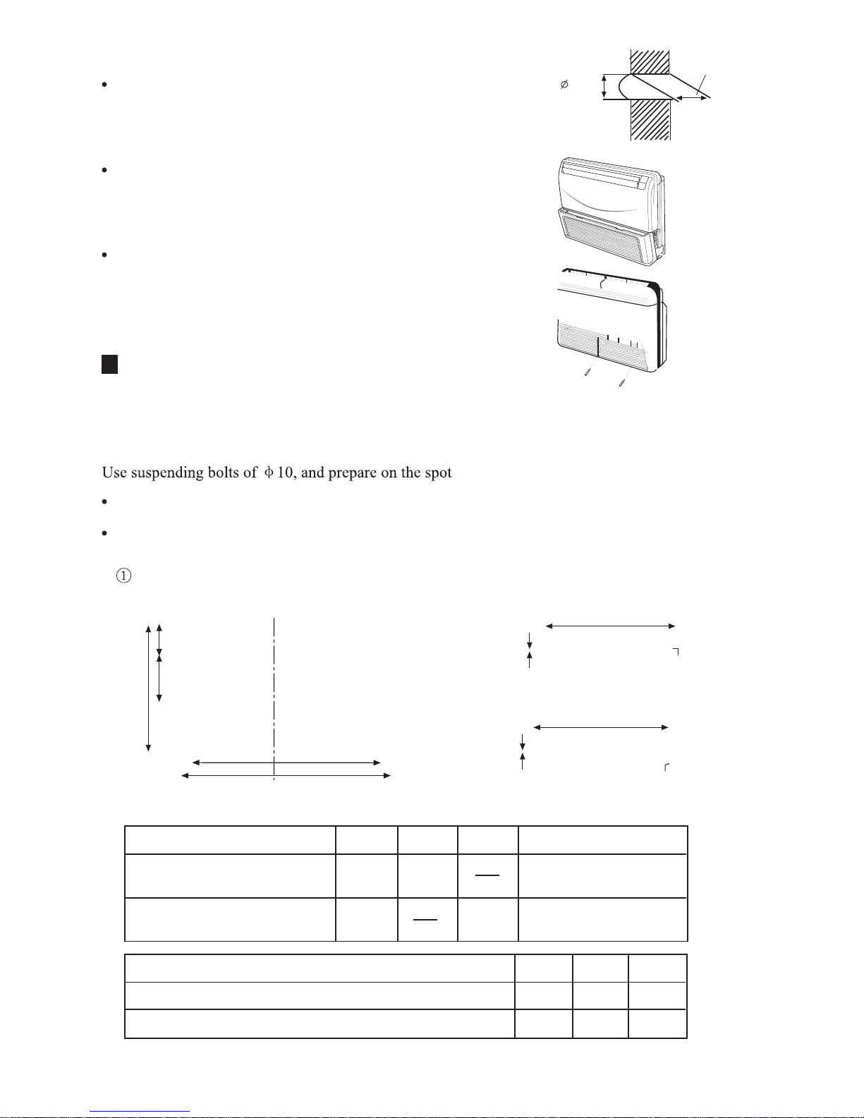
Prior to installation
Drill a hole of 70 mm diameter through the wall with its outside
inclining lower slightly. Install a guard ring and then seal it with
gesso or putty.
As shown in the diagram at the right, open intake barrier . (AC092,
122,162FEAHA, AC092,122,162FEBHA)
As shown in the diagram at the right, remove two screw snails as
shown and take right-side intake barrier down. (AC182,242,
282FEAHA,AC182,242,282FEBHA.
Installation of Air Conditioner
Installation in under ceiling
1. Installation of suspending bolts
Installation of supporting frame for AC092,122,142,162FEAHA, AC092,122,142,162FEBHAtype
should be internally suspended.
Installation of supporting frame for AC182,242,282FEAHA,AC182,242,282FEBHA type should be
externally suspended.
Installation position of suspending bolts
Internal suspension
External suspension
(Note: Here we only use simple drawing as figurations of the series are different)
Type
AC092,122,142,162FEAHA,
AC092,122,142,162FEBHA
AC182,242,282FEAHA,
AC182,242,282FEBHA
A (mm) B (mm) C (mm) Installation mode
990 990
1332 1244
Internal suspension
External suspension
Type
AC092,122,142,162FEAHA,AC092,122,142,162FEBHA
AC182,242,282FEAHA, AC182,242,282FEBHA
D (mm) E (mm) F (mm)
655 200 175
710 325 143
Space length between supending bolts
D
E
F
A
B
Space length between
suspending bolts
Blot hole for installaiton
4-12x27
Space length between
suspending bolts
Suspending bolt
less than 40mm.
C
Space length between
suspending bolts
Suspending bolt
less than 40mm.
B
Hole through the wall
Depth of
the wall
Profile chart of hole through the wall
Indoor side outdoor side
70mm
 Loading...