

SYJS-05-2018Rev.D Edition: 2018-05
Smart Power

Smart Power
CONTENTS
Part 1 General Information .......................................................................................................................................1
1. Nomenclature ......................................................................................................................................................2
2. Line up .................................................................................................................................................................3
3. Feature ................................................................................................................................................................5
Part 2 Indoor Units--4-Way Cassette Type ..............................................................................................................7
1. Feature ................................................................................................................................................................8
2. Specication ........................................................................................................................................................9
3. Dimension .........................................................................................................................................................15
4. Wiring Diagram ..................................................................................................................................................16
5. Air Velocity and Temperature Distribution ..........................................................................................................17
6. Sound Pressure Level .......................................................................................................................................21
7. Installation .........................................................................................................................................................24
8. Test run ..............................................................................................................................................................30
Part 3 Indoor Units-Medium ESP Duct Type .........................................................................................................31
1. Feature ..............................................................................................................................................................32
2. Specication ......................................................................................................................................................34
3. Dimension .........................................................................................................................................................41
4. Wiring Diagram ..................................................................................................................................................43
5. Airow and Static Pressure Chart ......................................................................................................................46
6. Instalaltion .........................................................................................................................................................49
7. Sound Pressure Level .......................................................................................................................................58
Part 4 Indoor Unit-High ESP Duct Type ................................................................................................................59
1. Feature ..............................................................................................................................................................60
2. Specication ......................................................................................................................................................62
3. Dimension .........................................................................................................................................................68
4. Wiring Diagram ..................................................................................................................................................70
5. Airow and Static Pressure Chart ......................................................................................................................72
6. Installation .........................................................................................................................................................75
7. Sound Pressure Level .......................................................................................................................................87
Part 5 Outdoor Units ...............................................................................................................................................93
1. Specication ......................................................................................................................................................94
2. Dimension .......................................................................................................................................................103
3. Piping Diagram ................................................................................................................................................106
4. Wiring Diagram ................................................................................................................................................108
5. Noise Level ......................................................................................................................................................113
6. Outdoor Performace Curves ...........................................................................................................................121
7. Installation .......................................................................................................................................................130
Part 6 Electric Control and Toublleshooting ....................................................................................................... 152
1. Indoor Unit ......................................................................................................................................................153
2. Indoor Unit Dip Switch Setting .........................................................................................................................159
3. Outdoor Unit PCB Photo .................................................................................................................................165
4. Failure Code ....................................................................................................................................................172
5. Instructions of Parameters & Error Code Checking ........................................................................................195
6. Function ...........................................................................................................................................................204
7. Controller ......................................................................................................................................................216
Appendix Sensor Characteristic ..........................................................................................................................232

Smart Power
Part 1 General Information
1. Nomenclature ..........................................................................................................................................................2
2. Line up .....................................................................................................................................................................3
3. Feature ....................................................................................................................................................................5
1
1. Nomenclature
Smart Power
071 R GH EU 11 N
Climate & power supply
A: T1 & 220-240V, 1Ph, 50Hz
G: T1 & 220-240V, 1Ph, 50/60Hz
K: T1 & 380-400V, 3PH, 50/60Hz
Inverter/xed-speed
A: Fixed-speed
R: Inverter
Category
E: R410A
Version
1: Version 1
Appearance character
Cooling capacity
071 means 7.1kW;
Series
H: Smart portocol, power inverter
Type
B: Cassette
D: Duct
U: Outdoor unit
Indoor/outdoor unit
A: Indoor unit
1: 1:1 Outdoor unit
2: 1:2 Outdoor unit
2
Smart Power
2. Line up
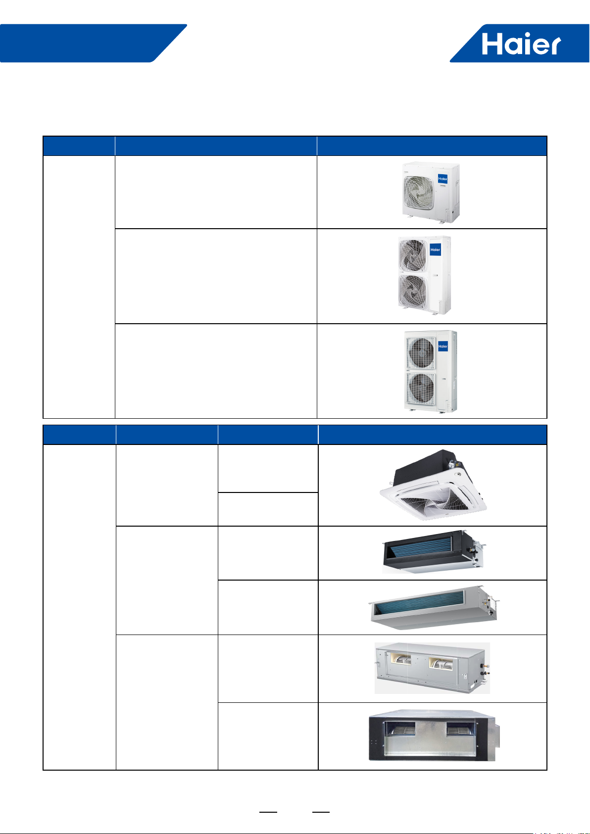
Outdoor unit
Model Apperance
1UH071N1ERG
1UH090N1ERG
1UH105N1ERG
1UH125P1ERG
1UH125P1ERK
1UH140P1ERK
1UH160P1ERG
Indoor unit
1UH200W1ERK 1UH250W1ERK
Model Apperance
ABH071H1ERG
ABH090H1ERG
4-Way Cassette
Medium Esp Duct
High ESP Duct
ABH105H1ERG
ABH125K1ERG
ABH140K1ERG
ADH071M1ERG
ADH071M3ERG
ADH090M1ERG
ADH105M1ERG
ADH125M1ERG
ADH140M1ERG
ADH105H1ERG
ADH125H1ERG
ADH140H1ERG
ADH160H1ERG
ADH200H1ERG
ADH250H1ERG
3
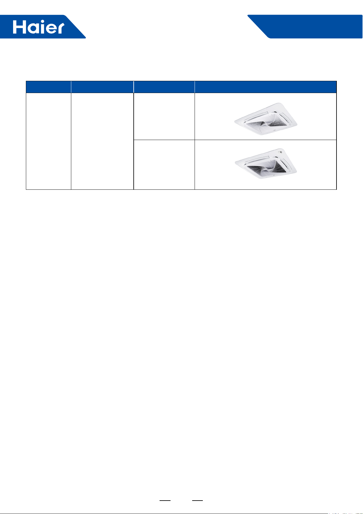
Panel 4-Way Cassette
Smart Power
Model Apperance
PB-950KB
PB-950MB
4
Smart Power
3. Feature
Double side 4 handles
Because of double side 4 handles design, it is very easy for
2 peoples carry it.
Stylish Design
Built-in valve design
The new built-in valve design, it can realize 4 way pipe
connection (front, rear, right, down) , it is more beautiful and
easy installation.
Easy Installation
"888" digital test panel
All running parameters & error code can be checked from
"888" digital display, installer can make easy work.
Wired controller data check
Running parameters can be checked by controller, if
installer is not easy to go to the outdoor unit site, just stay
indoor to check, installer can make easy work.
5
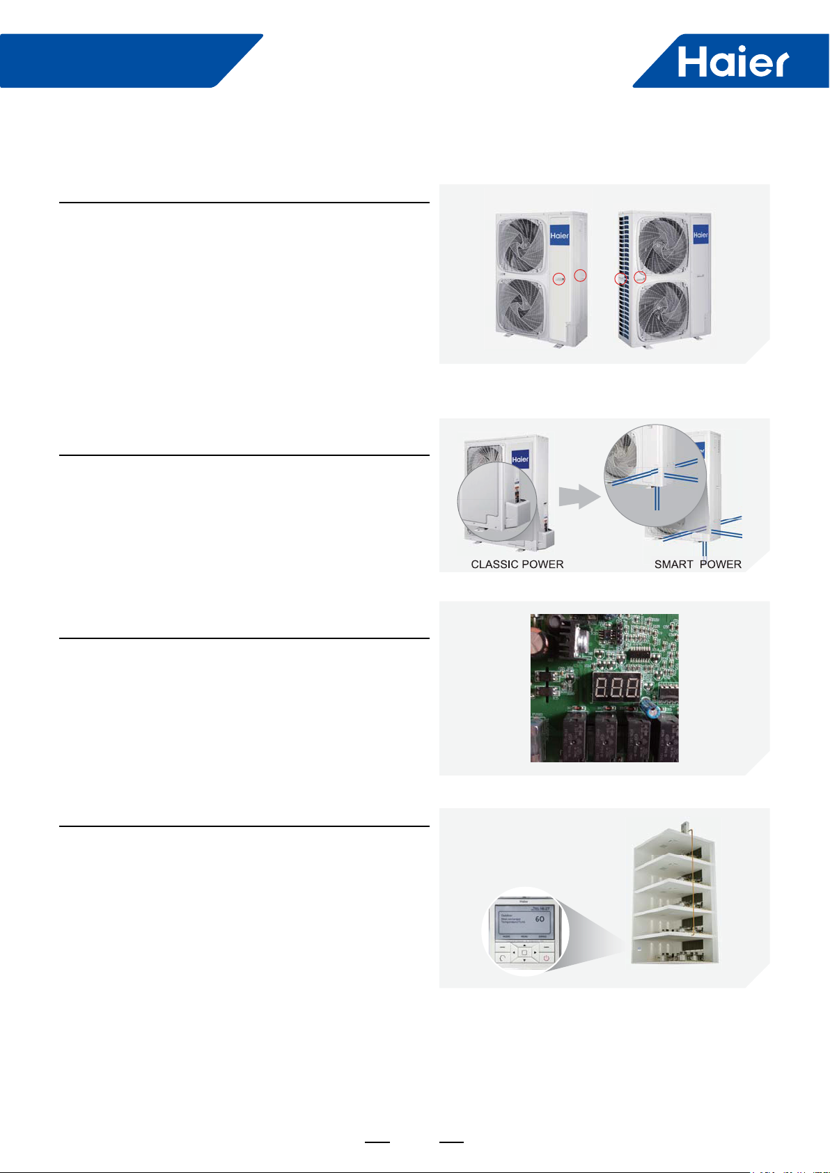
Low Sound Level
Super big inlet grille
Compared to conventional air inlet grill, we enlarge the air
inlet area by 23%, lower air speed & lower the sound level.
New designed fan
The diameter of new fan is enlarged based on acrodynamic
theory, so that there is the least resistance against airow.
Reduce 3dB (A) for sound level.
Smart Power
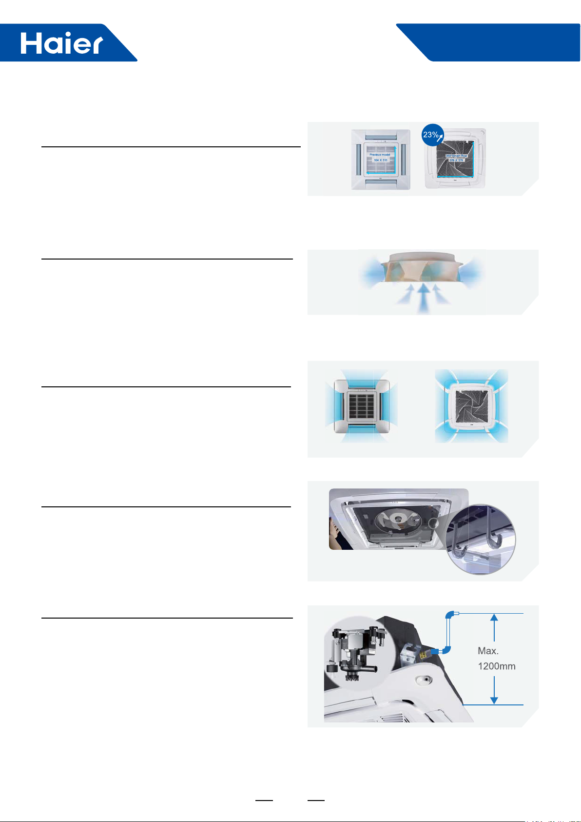
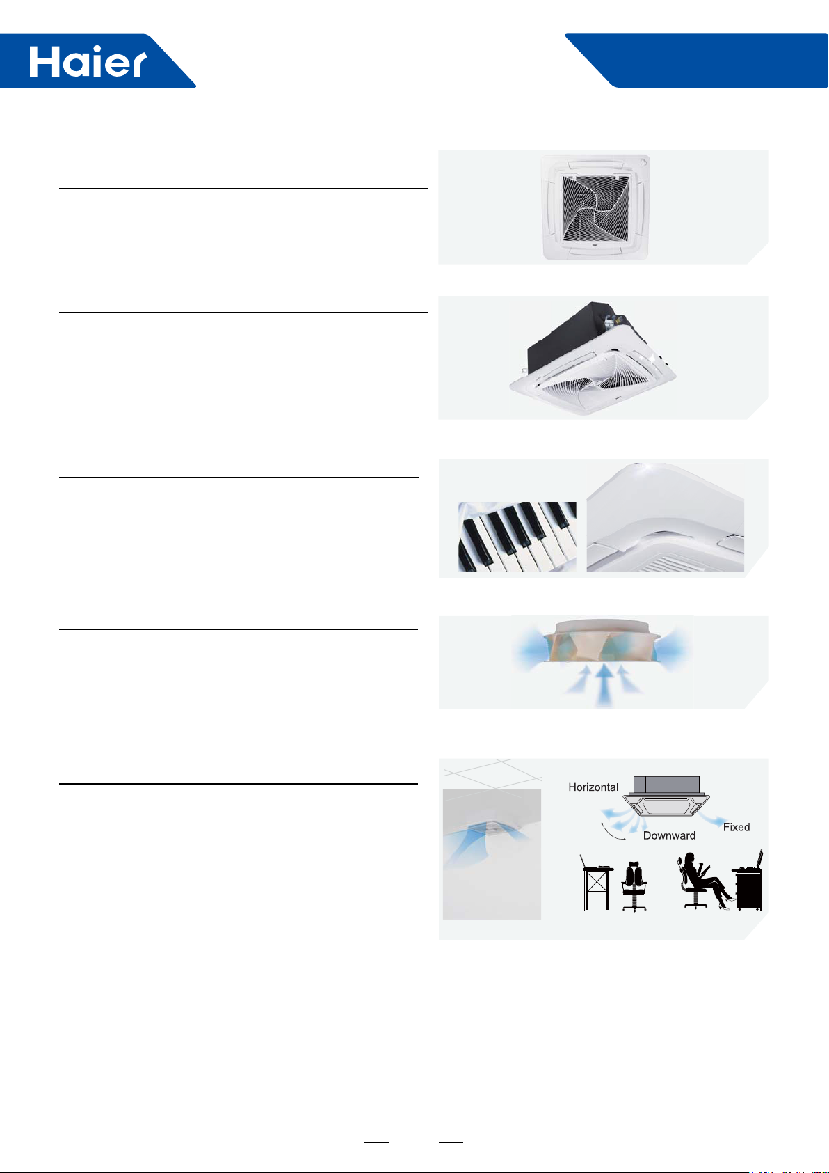
Comfort Airflow
360° air supply
360° air supply without blind spot.
Easy Installation
Convenient clip
There is clip to lock the panel. Just one installer can
nish the screwing for panel. Save manpower and easy
installation.
High lift-up drain pump
It can lifts condensed water up to 1200mm, which is more
exible to install the duct according to the layout.
4 way air ow
Unique 360° air ow design
6

Smart Power
Part 2 Indoor Units--4-Way Cassette Type
1. Feature ....................................................................................................................................................................8
2. Specication ............................................................................................................................................................9
3. Dimension..............................................................................................................................................................15
4. Wiring Diagram ......................................................................................................................................................16
5. Air Velocity and Temperature Distribution ..............................................................................................................17
6. Sound Pressure Level ...........................................................................................................................................21
7. Installation .............................................................................................................................................................24
8. Test run ..................................................................................................................................................................30
7
1. Feature
Stylish Design
"Spiral" panel
"Spiral" concept, "Haier" image.
Flap is closed when air conditioner off
There is no crack from the ap and the panel when the air
conditioner off. More elegance.
Smart Power
ABS material panel
ABS material makes the panel "piano white", different from
"dark white" PS material color. The panel and ap are
the same material. After 10 years, the panel color won't
change to yellow color because the ABS material prevents
discoloration against light raying.
New designed fan
The diameter of new fan is enlarged based on acrodynamic
theory, so that there is the least resistance against airow.
Reduce 3dB (A) for sound level.
Individual flap control
The four aps can be controlled individually according
to end users by controller, providing maximum comfort
throughout the room, it is a good solution to avoid "air
conditioning disease".
Adiustable
Comrner installation solution
8
Comfort solution
Smart Power
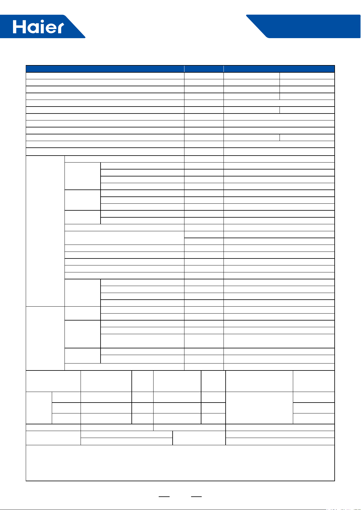
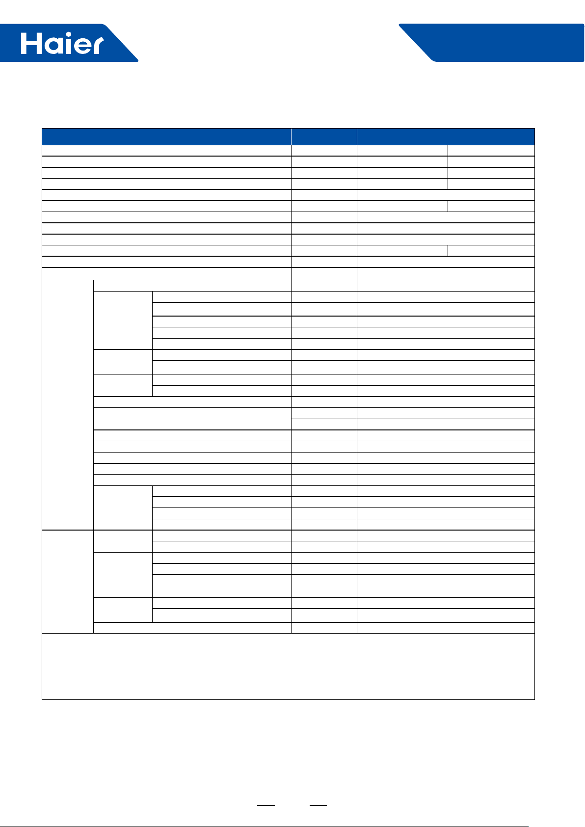
2. Specication
Item Model ABH071H1ERG/1UH071N1ERG
Function Cooling Heating
Capacity kW 7.1 (2.0~8.0) 7.8 (2.0~9.0)
Sensible heat ratio 0.72 /
Total power input kW 1.89 (0.4~3.2) 2.0 (0.4~3.2)
Max. power input W 4000
AEER or ACOP W/W 3.65 3.8
Dehumidifying capacity 10
Power cable 4.0mm
Power source N, V, Hz 1PH, 220-240V~, 50/60Hz
Running/Max. Running current A/A 8.7 (2.0-17.5)/17.5 9.1 (2.0-17.5)/17.5
Start current A 3
Circuit breaker A 30
Unit model (color) ABH071H1ERG
Type×Number CENTRIFUGALX1
Fan
Heat
exchanger
Dimension
Indoor unit
Piping
Cooling Pdesignc (kW) : 7.1kW SEER/CLASS 6.3/A++
Heating
Tdesignh: -10°C Tbivalent: -8°C TOL: -20°C Elbu: 0
Max. cooling condition
Norminal condition:
Indoor temperature (cooling) : 27DB (°C)/19WB (°C) , Indoor temperature (heating) : 20DB (°C)
Outdoor temperature (cooling) : 35DB (°C)/24WB (°C) , Outdoor temperature (heating) : 7DB (°C)/6WB (°C)
The noise level will be measured in the third octave band limited values, using a Real Time Analyser calibrated sound intensity meter.
It is a sound pressure noise level.
Drainage pipe (material, I.D./O.D.) mm PVC 26/32
Controller (O-Optional, S-Standard)
Fresh air hole dimension mm 75
Electricity heater kW /
Sound power noise level (H) dB (A) 52
Sound pressure noise level (H-M-L-SL) dB (A) 36/33/29/26
Weight (Net/Shipping) kg/kg 31/36
Panel
Refrigerant
Pipe
Between
I.D &O.D
Connection method Flared
Average Pdesignh (-10°C) 6.0kW SCOP/CLASS 4.2/A+
Warmer Pdesignh (2°C) 6.5kW SCOP/CLASS 4.8/A++ 1615
Colder Pdesignh (-22°C) / SCOP/CLASS / /
Speed (H-M-L-SL) r/min 500/400/300/250
Fan motor output/input power W 72/112
Air-ow (H-M-L-SL) m
Type/Diameter mm Inner grooved pipe/φ7.0
Row 2
Total area m
External (L×W×H) mm×mm×mm 840/840/246
Package (L×W×H) mm×mm×mm 990/990/310
Model PB-950KB/PB-950MB
External dimensions (W/D/H) mm 950/950/50
Shipping dimensions (W/D/H) mm 1000/1000/110
Net weight/Shipping weight kg 6.5/9
Type/Charge g R410A/2500
Recharge quantity g/m 45
Liquid mm 9.52
Gas mm 15.88
Max pipe length
(without charge refrigerant)
MAX. Drop m 30
MAX. Piping length m 50
Indoor temperature: 32°C/23°C Max. heating
Outdoor temperature: 46°C/-°C Outdoor temperature: 24°C/18°C
-3×m3
/h 2.4
3
/h 1260/1070/820/680
2
Wired YR-E16A(O)/YR-E17(O)
Infrared YR-HBS01(S)
m 20
QCE (Annual electricity
consumption for cooling)
kWh:
QHE (Annual electricity
consumption for heating)
kWh:
Indoor temperature: 27°C/-°C
condition
2
/
377
1899
9
Smart Power
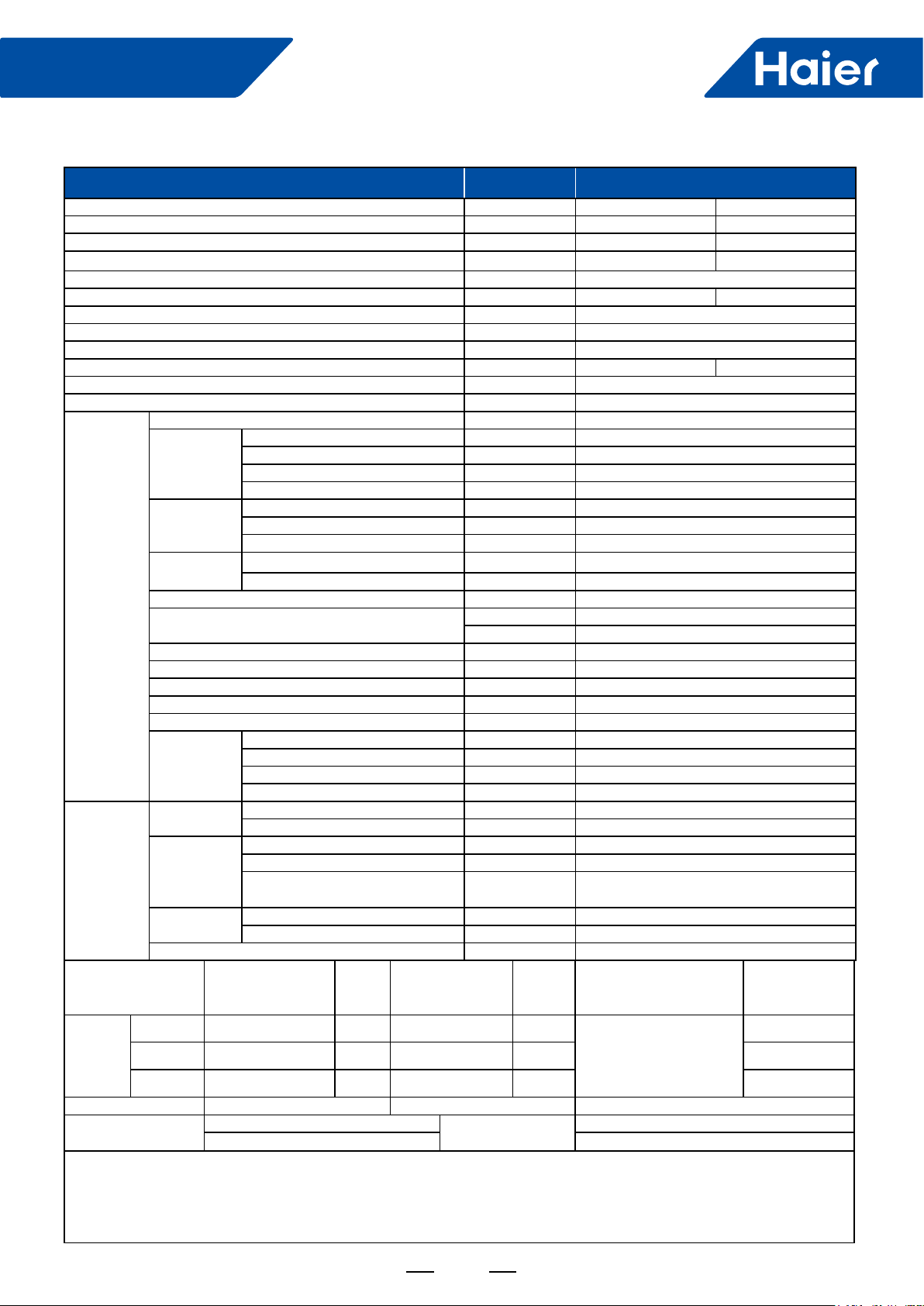
Item Model ABH090H1ERG/1UH090N1ERG
Function Cooling Heating
Capacity kW 9 (2.5~10) 10.1 (2.5~11)
Sensible heat ratio 0.72 /
Total power input kW 2.56 (0.5~3.5) 2.69 (0.5~3.5)
Max. power input W 4400
AEER or ACOP W/W 3.44 3.87
Dehumidifying capacity 10
Power cable 4.0mm
Power source N, V, Hz 1PH, 220-240V~, 50/60Hz
Running/Max. Running current A/A 11.6 (2.3-19.2)/19.2 11.9 (2.3-19.2)/19.2
Start current A 3
Circuit breaker A 30
Unit model (color) ABH090H1ERG
Type×Number CENTRIFUGALX1
Fan
Speed (H-M-L-SL) r/min 600/500/400/350
Fan motor output/input power W 77/125
Air-ow (H-M-L-SL) m
Type/Diameter mm Inner grooved pipe/φ7.0
Row 2
Total area m
External (L×W×H) mm×mm×mm 840/840/246
Package (L×W×H) mm×mm×mm 990/990/310
Indoor unit
Heat
exchanger
Dimension
Drainage pipe (material, I.D./O.D.) mm PVC 26/32
Controller (O-Optional, S-Standard)
Fresh air hole dimension mm 75
Electricity heater kW /
Sound power noise level (H) dB (A) 57
Sound pressure noise level (H-M-L-SL) dB (A) 41/36/33/29
Weight (Net/Shipping) kg/kg 31/36
Model PB-950KB/PB-950MB
Panel
External dimensions (W/D/H) mm 950/950/50
Shipping dimensions (W/D/H) mm 1000/1000/110
Net weight/Shipping weight kg 6.5/9
Refrigerant
Type/Charge g R410A/2500
Recharge quantity g/m 45
Liquid mm 9.52
Gas mm 15.88
Max pipe length
Piping
Pipe
(without charge refrigerant)
Between
I.D &O.D
MAX. Drop m 30
MAX. Piping length m 50
Connection method Flared
Cooling Pdesignc (kW) : 9kW SEER/CLASS 6.3/A++
Average Pdesignh (-10°C) 8.1kW SCOP/CLASS 4.1/A+
Heating
Warmer Pdesignh (2°C) 8.8kW SCOP/CLASS 4.8/A++ 2416
Colder Pdesignh (-22°C) / SCOP/CLASS / /
Tdesignh: -10°C Tbivalent: -8°C TOL: -20°C Elbu: 0
Max. cooling condition
Indoor temperature: 32°C/23°C Max. heating
Outdoor temperature: 46°C/-°C Outdoor temperature: 24°C/18°C
condition
Norminal condition:
Indoor temperature (cooling) : 27DB (°C)/19WB (°C) , Indoor temperature (heating) : 20DB (°C)
Outdoor temperature (cooling) : 35DB (°C)/24WB (°C) , Outdoor temperature (heating) : 7DB (°C)/6WB (°C)
The noise level will be measured in the third octave band limited values, using a Real Time Analyser calibrated sound intensity meter.
It is a sound pressure noise level.
-3×m3
/h 2.5
3
/h 1470/1260/1050/940
2
2
/
Wired YR-E16A(O)/YR-E17(O)
Infrared YR-HBS01(S)
m 20
QCE (Annual electricity
consumption for cooling)
kWh:
QHE (Annual electricity
consumption for heating)
kWh:
Indoor temperature: 27°C/-°C
516
2798
10
Smart Power
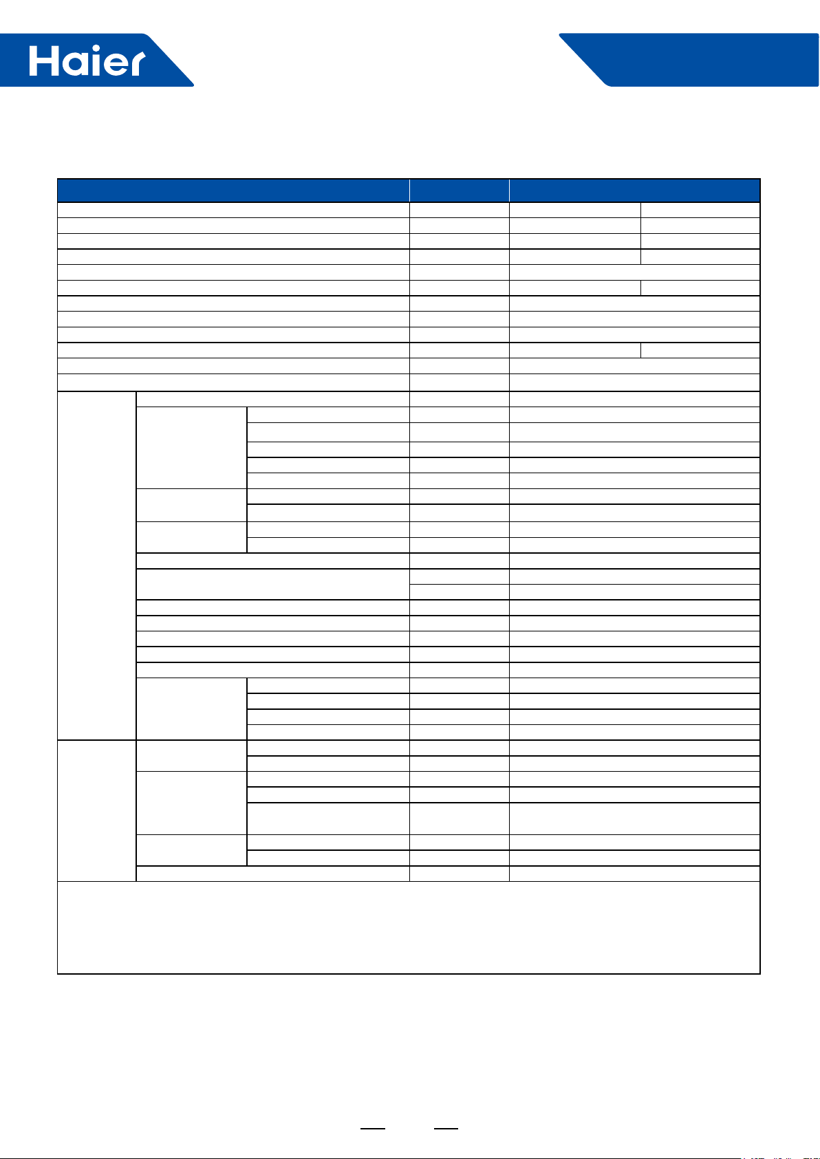
Item Model ABH105H1ERG/1UH105N1ERG
Function Cooling Heating
Capacity kW 10 (2.5~11) 10.6 (2.5~11.3)
Sensible heat ratio 0.72 /
Total power input kW 2.99 (0.5~4.0) 2.86 (0.5~4.0)
Max. power input W 4900
AEER or ACOP W/W 3.29 3.64
Dehumidifying capacity 10
Power cable 4.0mm
Power source N, V, Hz 1PH, 220-240V~, 50/60Hz
Running/Max. Running current A/A 13.6 (2.3-20)/20 12.7 (2.3-20)/20
Start current A 3
Circuit breaker A 30
Unit model (color) ABH105H1ERG
Type×Number CENTRIFUGALX1
Fan
Speed (H-M-L-SL) r/min 650/550/450/400
Fan motor output/input power W 82/134
Air-ow (H-M-L-SL) m
Type/Diameter mm Inner grooved pipe/φ7.0
Row 2
Total area m
External (L×W×H) mm×mm×mm 840/840/246
Package(L×W×H) mm×mm×mm 990/990/310
Indoor unit
Heat
exchanger
Dimension
Drainage pipe (material, I.D./O.D.) mm PVC 26/32
Controller (O-Optional, S-Standard)
Fresh air hole dimension mm 75
Electricity heater kW /
Sound power noise level (H) dB (A) 62
Sound pressure noise level (H-M-L) dB (A) 45/42/38/34
Weight (Net/Shipping) kg/kg 31/36
Model PB-950KB/PB-950MB
Panel
External dimensions (W/D/H) mm 950/950/50
Shipping dimensions (W/D/H) mm 1000/1000/110
Net weight/Shipping weight kg 6.5/9
Refrigerant
Type/Charge g R410A/2500
Recharge quantity g/m 45
Liquid mm 9.52
Gas mm 15.88
Max pipe length
Piping
Pipe
(without charge refrigerant)
Between
I.D &O.D
MAX. Drop m 30
MAX. Piping length m 50
Connection method Flared
Cooling Pdesignc (kW) : 10kW SEER/CLASS 6.8/A++
Average Pdesignh (-10°C) 8.2kW SCOP/CLASS 4.1/A+
Heating
Warmer Pdesignh (2°C) 8.8kW SCOP/CLASS 4.8/A++ 2566
Colder Pdesignh (-22°C) / SCOP/CLASS / /
Tdesignh: -10°C Tbivalent: -8°C TOL: -20°C Elbu: 0
Max. cooling condition
Indoor temperature: 32°C/23°C Max. heating
Outdoor temperature: 46°C/-°C Outdoor temperature: 24°C/18°C
condition
Norminal condition:
Indoor temperature (cooling) : 27DB (°C)/19WB (°C) , Indoor temperature (heating) : 20DB (°C)
Outdoor temperature (cooling) : 35DB (°C)/24WB (°C) , Outdoor temperature (heating) : 7DB (°C)/6WB (°C)
The noise level will be measured in the third octave band limited values, using a Real Time Analyser calibrated sound intensity meter.
It is a sound pressure noise level.
-3×m3
/h 3
3
/h 1680/1530/1320/1190
2
2
/
Wired YR-E16A(O)/YR-E17(O)
Infrared YR-HBS01(S)
m 20
QCE (Annual electricity
consumption for cooling)
kWh:
QHE (Annual electricity
consumption for heating)
kWh:
Indoor temperature: 27°C/-°C
538
2900
11
Smart Power
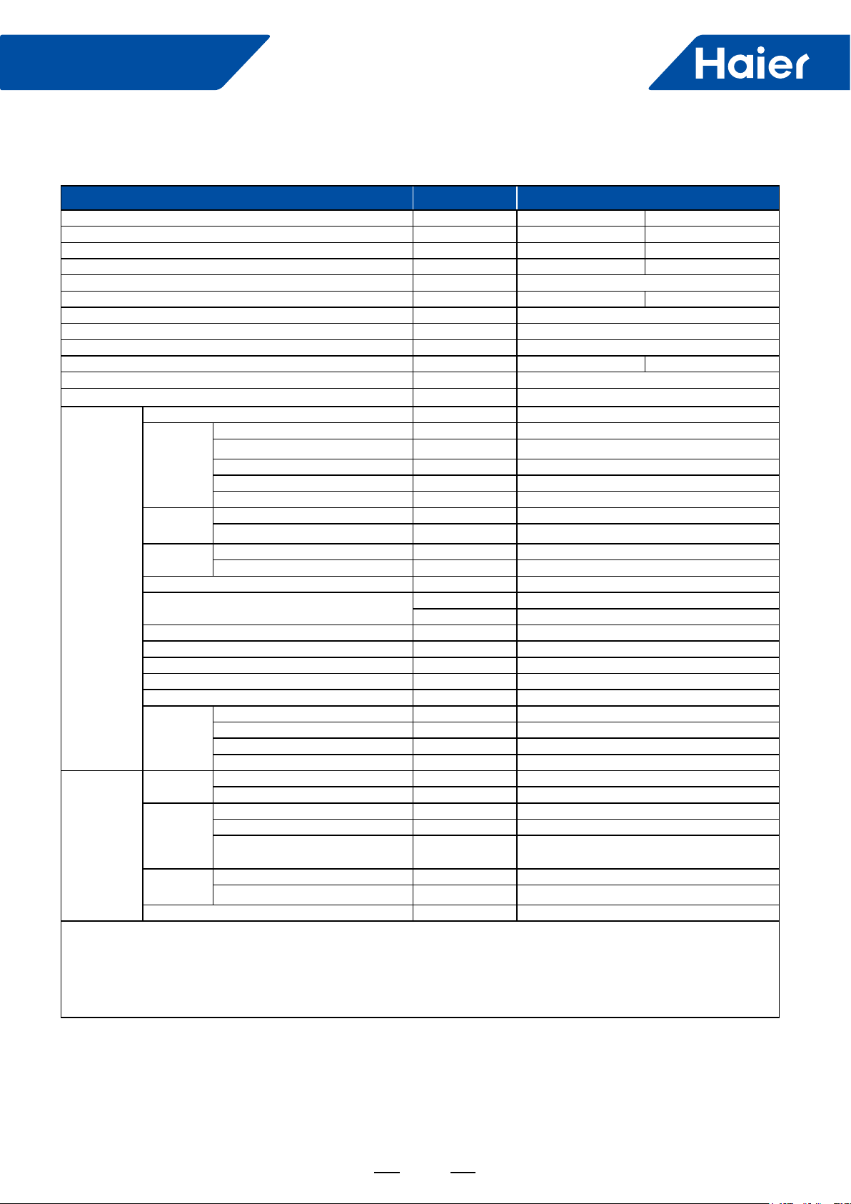
Item Model ABH125K1ERG/1UH125P1ERK
Function Cooling Heating
Capacity kW 12.5 (3.5~14.5) 13.1 (4~17)
Sensible heat ratio 0.74
Total power input kW 3.67 (1.0-6.0) 3.71 (1.0-6.0)
Max. power input W 7000
AEER or ACOP W/W 3.38 3.50
Dehumidifying capacity 10
Connection cable (indoor to outdoor)
Power source N, V, Hz 3PH~, 380~415, 50/60Hz
Running/Max. Running current A/A 6.1/10.8 6.3/10.8
Start current A 3
Circuit breaker
Unit model (color) ABH125K1ERG
Type×Number CENTRIFUGALX1
Speed (H-M-L)
Fan
Fan motor input power kW 0.12
Fan motor output power kW 0.09
Air-ow (H-M-L) m
Type/Diameter mm Inner grooved pipe/φ7.0
Total area
External (L×W×H) mm×mm×mm 840/840/288
Package (L×W×H) mm×mm×mm 990*990*380
Indoor unit
Heat exchanger
Dimension
Drainage pipe (material, I.D./O.D.) mm PVC 21/25
Controller (O-Optional, S-Standard)
Fresh air hole dimension mm 75
Electricity heater kW /
Sound power noise level (H) dB (A) 64
Sound pressure noise level (H-M-L) dB (A) 48/45/52
Weight (Net/Shipping) kg/kg 40/45
Model PB-950KB/PB-950MB
Panel
External dimensions (W/D/H) mm 950/950/50
Shipping dimensions (W/D/H) mm 1000/1000/110
Net weight/Shipping weight kg 6.5/9.0
Refrigerant
Type/Charge g R410A/3700
Recharge quantity g/m 45
Liquid mm 9.52
Gas mm 15.88
Max pipe length
Piping
Pipe
(without charge refrigerant)
Between I.D &O.D
MAX. Drop m 30
MAX. Piping length m 75
Connection method Flared
Norminal condition:
Indoor temperature (cooling) : 27DB (°C)/19WB (°C) , Indoor temperature (heating) : 20DB (°C)
Outdoor temperature (cooling) : 35DB (°C)/24WB (°C) , Outdoor temperature (heating) : 7DB (°C)/6WB (°C)
The noise level will be measured in the third octave band limited values, using a Real Time Analyser calibrated sound intensity meter.
It is a sound pressure noise level.
-3×m3
/h 4.9
A
r/min
3
/h 1950/1600/1440
2
m
3Ph, 40A(from outdoor)
750/650/500
4.0mm
/
2
Wired YR-E17(O)/ YR-E16A(O)
Infrared YR-HBS01(S)
m 30
12
Smart Power
Item Model ABH125K1ERG/1UH125P1ERG
Function Cooling Heating
Capacity kW 12.5 (3.5~14.5) 13.1 (4~17)
Sensible heat ratio 0.74
Total power input kW 3.67 (1.0-6.0) 3.71 (1.0-6.0)
Max. power input W 6500
AEER or ACOP W/W 3.38 3.51
Dehumidifying capacity 10
Power cable 6.0mm
Power source N, V, Hz 1, 220~240, 50/60
Running/Max. Running current A/A 17.0 (8.7-30.0)/30A 17.2 (8.7-30.0)/30A
Start current A 3
Circuit breaker
Unit model (color) ABH125K1ERG
Type×Number CENTRIFUGALX1
Speed (H-M-L)
Fan
Fan motor input power kW 0.12
Fan motor output power kW 0.09
Air-ow (H-M-L) m
Indoor unit
Heat
exchanger
Dimension
Drainage pipe (material, I.D./O.D.) mm PVC 21/25
Type/Diameter mm Inner grooved pipe/φ7.0
Total area
External (L×W×H) mm×mm×mm 840/840/288
Package (L×W×H) mm×mm×mm 990*990*380
Controller (O-Optional, S-Standard)
Fresh air hole dimension mm 75
Electricity heater kW /
Sound power noise level (H) dB (A) 64
Sound pressure noise level (H-M-L) dB (A) 48/45/42
Weight (Net/Shipping) kg/kg 40/45
Model PB-950KB/PB-950MB
Panel
External dimensions (W/D/H) mm 950/950/50
Shipping dimensions (W/D/H) mm 1000/1000/110
Net weight/Shipping weight kg 6.5/9.0
Refrigerant
Type/Charge g R410A/3700
Recharge quantity g/m 45
Liquid mm 9.52
Gas mm 15.88
Max pipe length
Piping
Pipe
(without charge refrigerant)
Between
I.D &O.D
MAX. Drop m 30
MAX. Piping length
Connection method Flared
Norminal condition:
Indoor temperature (cooling) : 27DB (°C)/19WB (°C) , Indoor temperature (heating) : 20DB (°C)
Outdoor temperature (cooling) : 35DB (°C)/24WB (°C) , Outdoor temperature (heating) : 7DB (°C)/6WB (°C)
The noise level will be measured in the third octave band limited values, using a Real Time Analyser calibrated sound intensity
meter. It is a sound pressure noise level.
-3×m3
/h 4.9
A
r/min
3
/h 1950/1600/1440
2
m
750/650/500
2
40
/
Wired YR-E17(O) or YR-E16A(O)
Infrared YR-HBS01 (S)
m 30
m
75
13
Smart Power
Item Model ABH140K1ERG/1UH140P1ERK
Function Cooling Heating
Capacity kW 13.4 (3.5~15.0) 14.5 (4.0~18.0)
Sensible heat ratio 0.74
Total power input kW 4.05 4.11
Max. power input W 7200
AEER or ACOP W/W 3.27 3.48
Dehumidifying capacity 10
Connection cable(
from outdoor to indoor)
Power source N, V, Hz
Running/Max. Running current A/A 6.8/11.0 7.0/11.0
Start current A 3
Circuit breaker
Unit model (color)
Type×Number
Speed (H-M-L)
Fan
Fan motor input power kW 0.12
Fan motor output power kW 0.09
Air-ow (H-M-L) m
Indoor unit
Heat
exchanger
Dimension
Drainage pipe (material, I.D./O.D.) mm PVC 21/25
Type/Diameter mm Inner grooved pipe/φ7.0
Total area
External (L×W×H) mm×mm×mm 840/840/288
Package (L×W×H) mm×mm×mm 990*990*380
Controller (O-Optional, S-Standard)
Fresh air hole dimension mm 75
Electricity heater kW /
Sound power noise level (H-M-L) dB (A) 64
Sound pressure noise level (H-M-L) dB (A) 48/45/42
Weight (Net/Shipping) kg/kg 32/38
Model PB-950KB/PB-950KB
Panel
External dimensions (W/D/H) mm 950/950/50
Shipping dimensions (W/D/H) mm 1000/1000/110
Net weight/Shipping weight kg 6.5/9.0
Refrigerant
Type/Charge g R410A/3700
Recharge quantity g/m 45
Liquid mm 9.52
Gas mm 15.88
Max pipe length
Piping
Pipe
(without charge refrigerant)
Between I.D
&O.D
MAX. Drop m 30
MAX. Piping length
Connection method Flared
Norminal condition:
Indoor temperature (cooling) : 27DB (°C)/19WB (°C) , Indoor temperature (heating) : 20DB (°C)
Outdoor temperature (cooling) : 35DB (°C)/24WB (°C) , Outdoor temperature (heating) : 7DB (°C)/6WB (°C)
The noise level will be measured in the third octave band limited values, using a Real Time Analyser calibrated sound intensity
meter. It is a sound pressure noise level.
-3×m3
/h
H05RN-F 4G 2.5mm2
4.9
3PH~, 380~415, 50/60Hz
A
3Ph,40A (
from outdoor)
ABH140K1ERG
CENTRIFUGALX1
r/min
3
/h 1950/1600/1440
2
m
750/650/550
/
Wired YR-E17(O) OR YR-E16A(O)
Infrared YR-HBS01 (S)
m 30
m
75
14
Smart Power
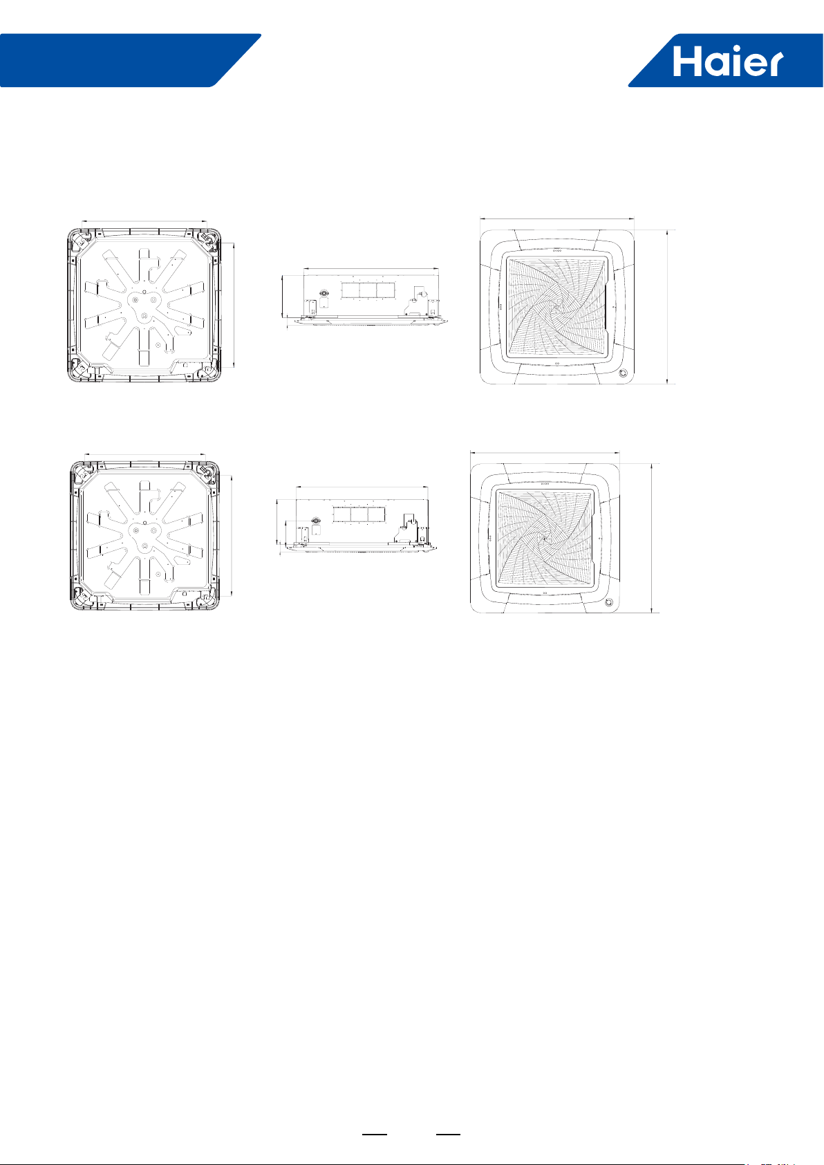
3. Dimension
ABH071H1ERG/ABH090H1ERG/ABH105H1ERG
765
765
ABH125K1ERG/ABH140K1ERG
246
47
950
840
59
950
765
765
288
47
168
950
840
59
950
15
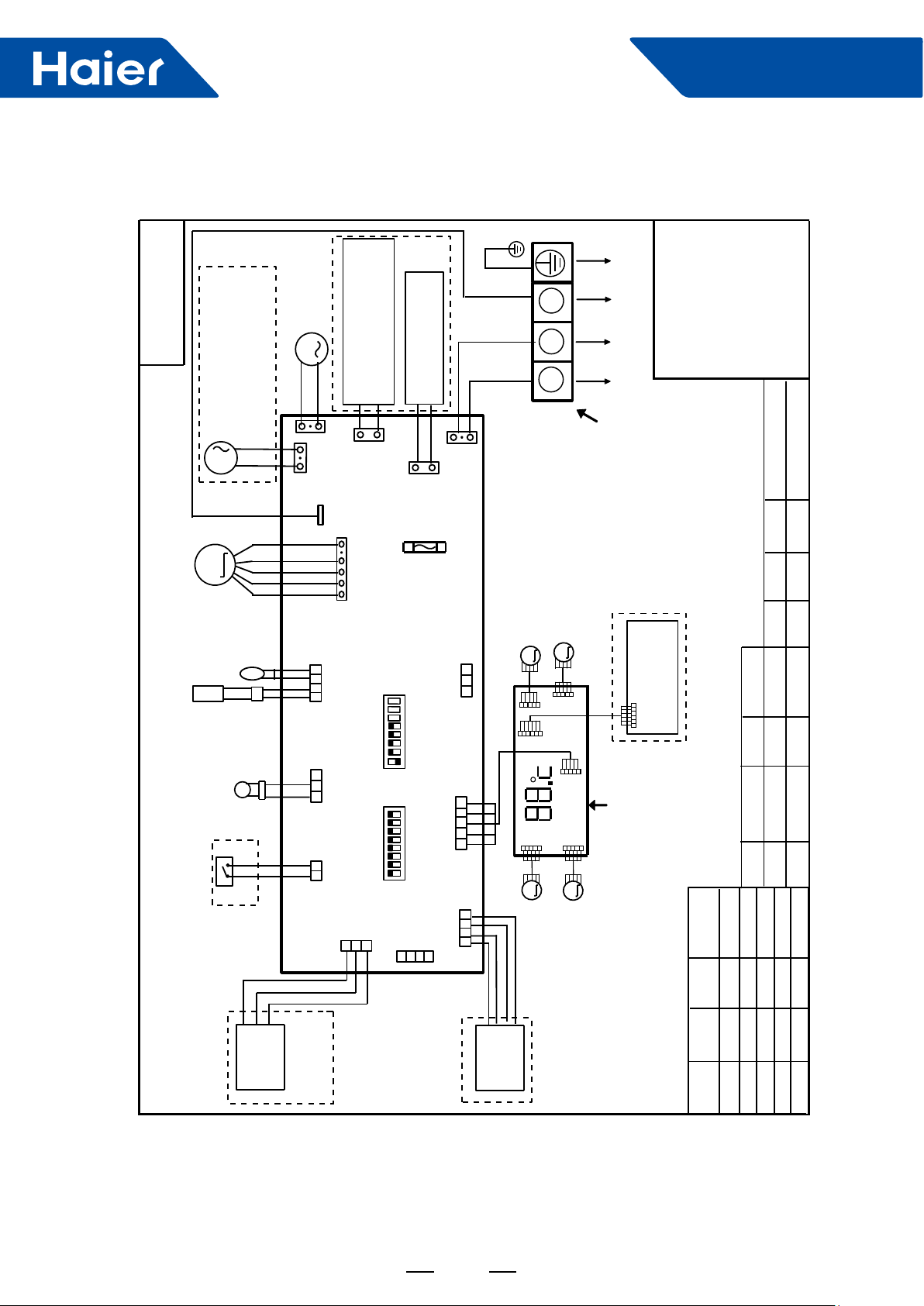
4. Wiring Diagram
0150516956
DC FAN MOTOR
PIPING
ROOM CARD
DRAIN
PUMP
M
ELECTRIC HEATING TERMINAL
FRESH AIR MOTOR /
EXTERNAL ALARM OUTPUT
(FUNCTION IN FUTURE )
( Contact rating_230VAC,3A)
M
CN10
CN9
CH1
M
.
ROOM
TEMP.
SENSOR
.
TEMP
SENSOR
FLOAT
SWITCH
CN6
CN3
CN19
CN1
CN11
BA
RATING_230VAC,3A
CN8
C
ELECTRIC HEATING
CONNECT TO THIRD PARTY RELAY
CN15
INDOOR UNIT
MAIN CONTROL
BOARD
SW1(BM1)
87654321
ON
OFF
SW3(BM3)
87654321
ON
OFF
CN26
B
A
THERMOSTAT / FUSE
L
FUSE
T5A 250VAC
CN13
CN14
CN4
RD
BLK
N
CN16
Y/G
WHT
LOUVER STEP
M
M
LOUVER
MOTOR2
CN2
.
3
2
1
LOUVER STEP
M
CN6
CN4
STEP MOTOR4
INDOOR UNIT
MOTOR1
CN1
CN7
CN3
M
LOUVER
STEP MOTOR3
Smart Power
Y/G:YELLOW/GREEN
RD:RED WHT:WHITE
BLK:BLACK
******************
TO OUT DOOR UNIT
TERMINAL BLOCK
INTELLIGENT
MOVE EYE DEVICE
I.R .RECEIVER
(WITH DIGITAL
DISPLAY)
CAPACITY
I.R .RECEIVER :
7.1
(KW)
9.0
INFRARED REMOTE
RECEIVER .
TEMP.:TEMPERATURE
(SLIM)
TYPE DEFINE
Cassette
ON
SW1-8
OFF
SW1-7
OFF
SW1-6
COOL HEAT
COOL ONLY
HEAT PUMP
SW1-5
Room card
SW1-4
OFF
ON
unavailable
available
ON
OFF
14.0
10.5
12.5
ON
OFF OFF ON
OFF ON
ON
ON
ON
ON
OFF
ON
OFF
SW1-3
C
B
A
WIRED
CONTROLLER
WiFi
MODULE
NOTE:
1.DASHED PARTS ARE OPTIONAL.
2.USER SHOULD NOT CHANGE THE
DIP SWITCH SW1 SW3 WITHOUT GUIDENCE
3.SW3-5->SW3-8 ARE USED FOR WIRED CONTROLLER
ADRESS SELECT. SW3-1->SW3-4 ARE RESERVED.
ON
SW1-2
ON
SW1-1
16

Smart Power
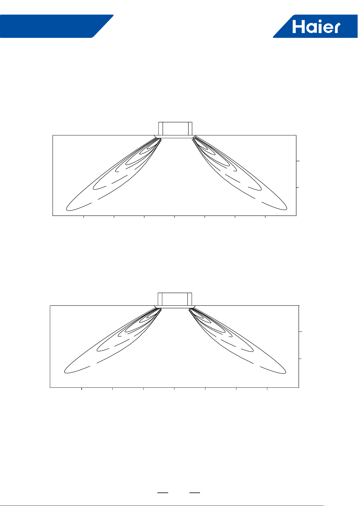
5. Air Velocity and Temperature Distribution
ABH071/090/105H1ERG:
a. Cooling/Air velocity distribution
Cooling
Blowy angle: 33
Air velocity distribution
2.5m/s
2.7m
2m
2.5m/s
1.5m/s
0.5m/s
4m
3m
b. Cooling/Temperature distribution
Cooling
Blowy angle: 33
Temperature distribution
17°C
20°C
1m
0m
1m
17°C
1.5m/s
2m2m
20°C
0.5m/s
3m
1m
0m
4m
2.7m
2m
1m
4m
22°C
3m
2m
1m
0m
17
1m
22°C
2m 3m
0m
4m
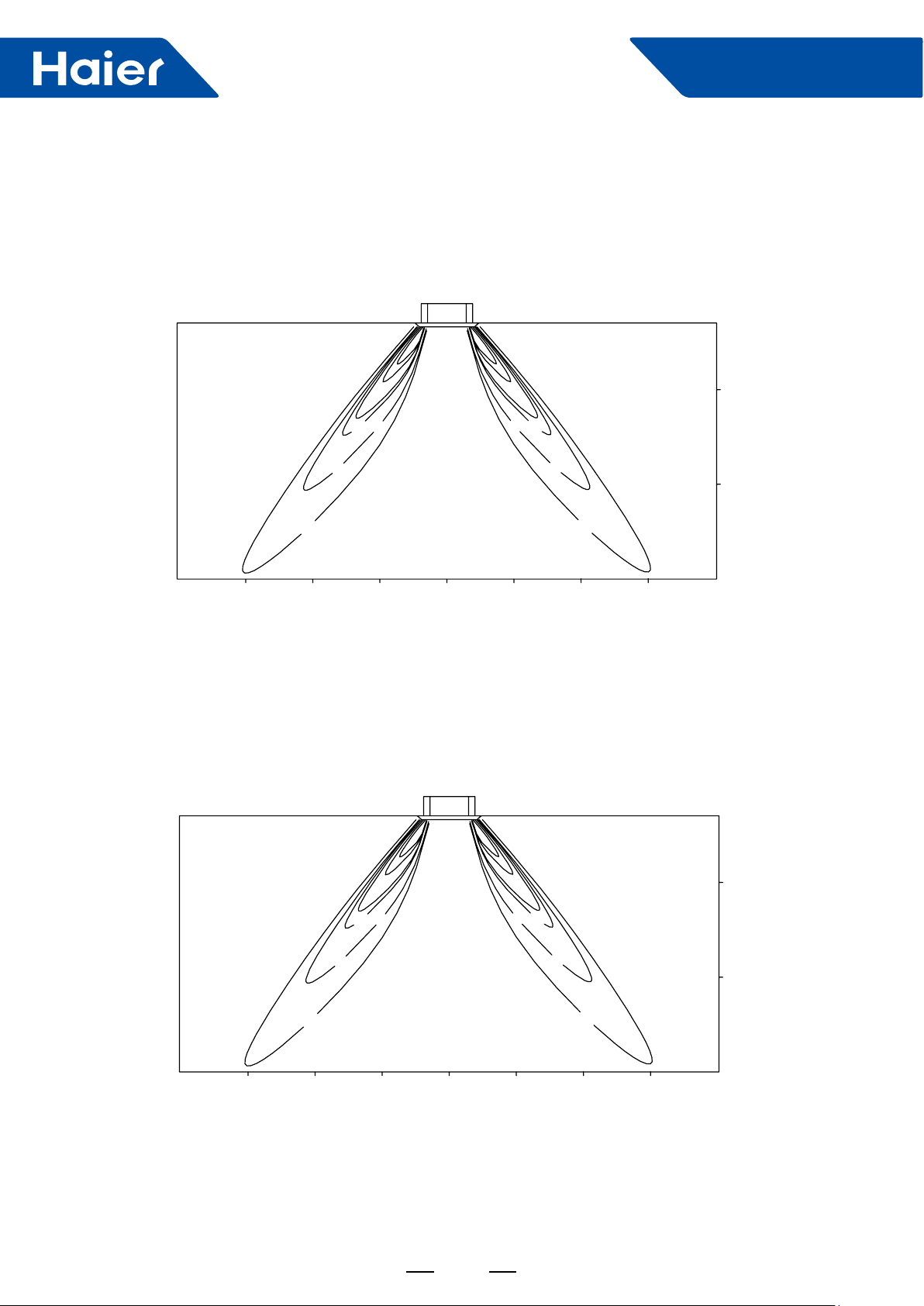
c. Heating/Air velocity distribution
Heating
Blowy angle: 60
Air velocity distribution
Smart Power
2.7m
2m
1.0m/s
4m
3m
d. Heating/Temperature distribution
Heating
Blowy angle: 60
Temperature distribution
2.0m/s
3.0m/s
1m
0m
3.0m/s
1m
2.0m/s
1.0m/s
2m2m
3m
4m
1m
0m
2.7m
4m
3m
26°C
29°C
32°C
1m
0m
18
32°C
1m
29°C
26°C
2m2m
3m
4m
2m
1m
0m
Smart Power
AB125-140
a. Cooling/Air velocity distribution
Cooling
Blowy angle: 33
Air velocity distribution
2.5m/s
2.7m
2m
3.0m/s
1.5m/s
0.5m/s
4m
3m
b. Cooling/Temperature distribution
Cooling
Blowy angle: 33
Temperature distribution
21°C
23°C
18°C
1m
0m
1m
18°C
2m2m
21°C
2.0m/s
1.0m/s
23°C
3m
1m
0m
4m
2.7m
2m
1m
4m
3m
1m
0m
19
1m
2m2m
3m
0m
4m

c. Heating/Air velocity distribution
Heating
Blowy angle: 60
Air velocity distribution
Smart Power
2.7m
2m
1.5m/s
3m
d. Heating/Temperature distribution
Heating
Blowy angle: 60
Temperature distribution
3.5m/s
2.5m/s
1m
0m
3.5m/s
1m
2.5m/s
1.5m/s
2m2m
1m
0m
3
m
4m4m
2.7m
2m
3m
27°C
33°C
30°C
1m 3 m
0m
1m
33°C
30°C
27°C
2m2m
20
1m
0m
4m4m
Smart Power
0.00
5.00
10.00
15.00
20.00
25.00
30.00
35.00
40.00
45.00
Sound pressure level DB
1/ 3 octave band frequency
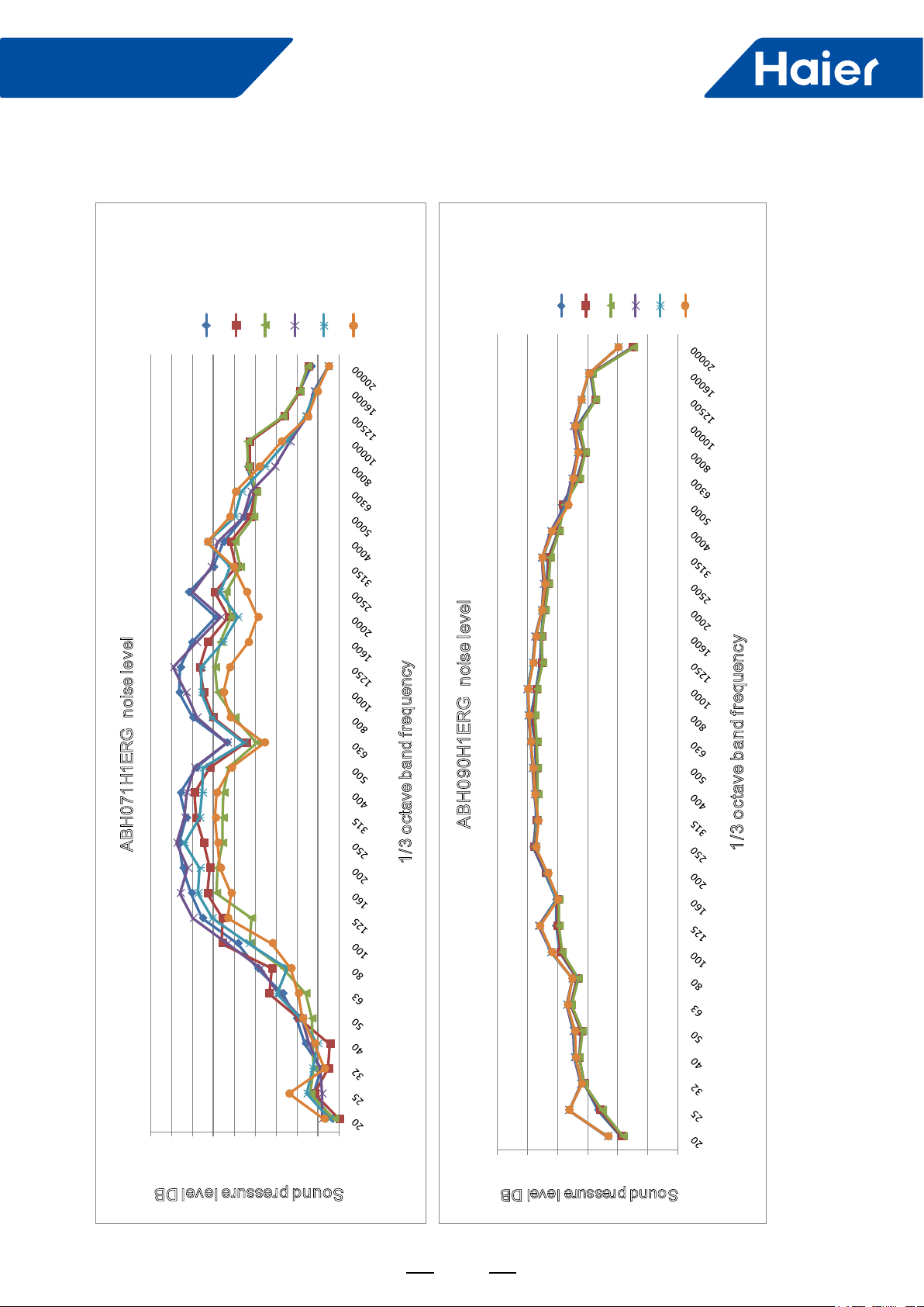
ABH071H1ERG noise level
Cooling-high
Cooling-med
Cooling-low
Heating-high
Heating-med
Heating-low
0
10
20
30
40
50
60
Sound pressure level DB
1/3 octave band frequency
ABH090H1ERG noise level
Cooling-high
Cooling-med
Cooling-low
Heating-
high
Heating-med
Heating-low
6. Sound Pressure Level
21
Smart Power
0.00
5.00
10.00
15.00
20.00
25.00
30.00
35.00
40.00
45.00
Sound pressure level DB
1/3 octave band frequency
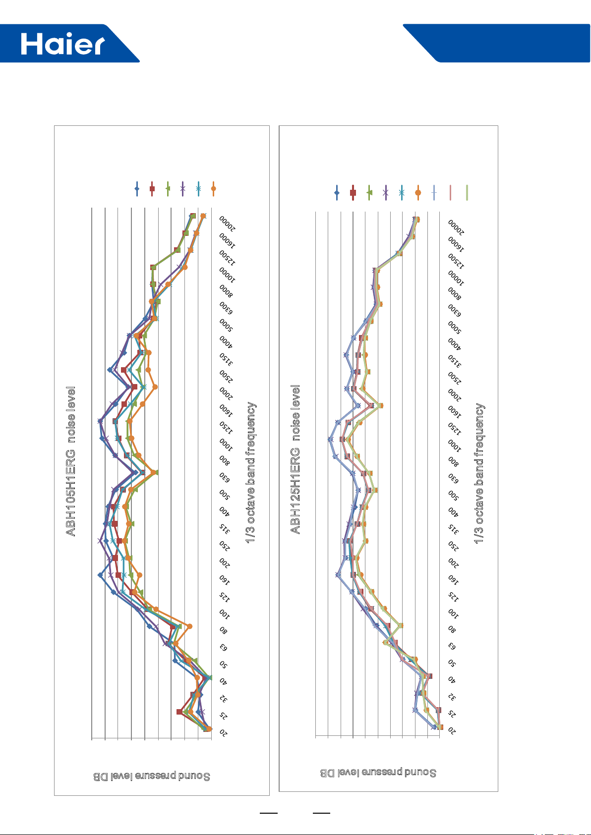
ABH105H1ERG noise level
Cooling-high
Cooling-med
Cooling-low
Heating-high
Heating-med
Heating-low
0.00
5.00
10.00
15.00
20.00
25.00
30.00
35.00
40.00
45.00
50.00
Sound pressure level DB
1/3 octave band frequency
ABH125H1ERG noise level
Cooling-high
Cooling-med
Cooling-low
Heating-high
Heating-med
Heating
-low
Fan-high
Fan-med
Fan-low
22
Smart Power
0.00
5.00
10.00
15.00
20.00
25.00
30.00
35.00
40.00
45.00
50.00
Sound pressure level DB
1/3 octave band frequency
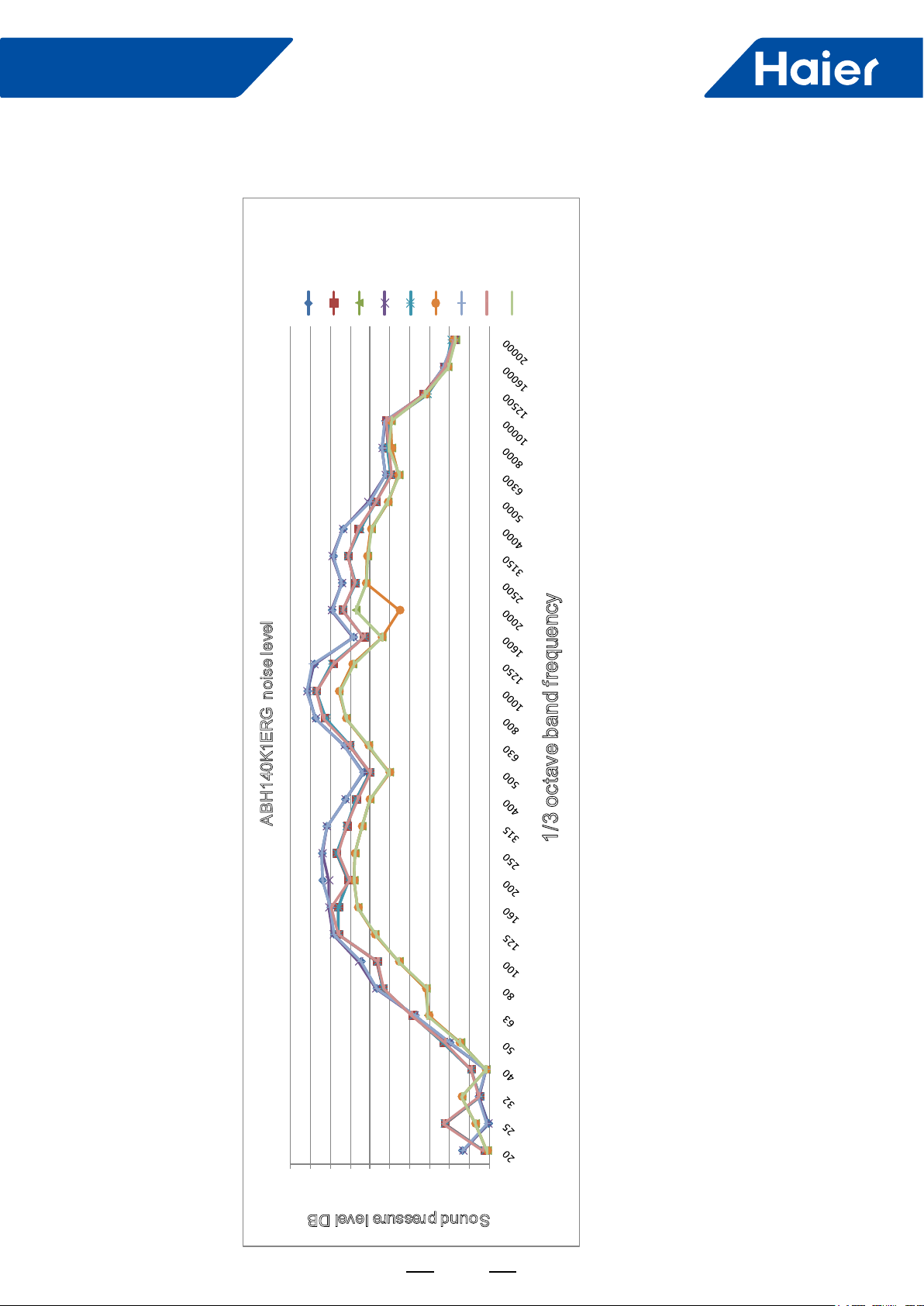
ABH140K1ERG noise level
Cooling
-high
Cooling
-med
Cooling-low
Heating-high
Heating-med
Heating
-low
Fan-high
Fan-med
Fan-low
23
Smart Power
7. Installation
7.1 Before installation <Don’t discard any accessories until comp>
• Determine the way to carry unit to installation place.
• Don’t remove packing until unit reaches installation place.
• If unpacking is unavoidable, protect unit properly.
7.2 Selection of installation place
(1) Installation place shall meet the following and agreed by customers:
• Place where proper air ow can be ensured.
• No block to air ow.
• Water drainage is smpoth.
• Place strong enough to support unit weight.
• Place where inclination is not evident on ceiling.
• Enough space for mainenance.
• Indoor and outdoor unit piping length is within limit. (Refer to Installation Manual for outdoor unit.)
• Indoor and outdoor unit, power cable, inter unit cable are at least 1 m away fromT.V. radio. This is helpful to avoid
picture disturbance and noise. (Even if 1 m is kept, noise can still appear if radio wave is strong)
(2) Ceiling height
Indoor unit can be installed on ceiling of 2.5-3m in height. (Refer to Foeld setting and Installation Manual of
ornament panel.)
(3) Install suspending bolt.
Check if the installation place is strong enough to hold weight. Take necessary measures in case it is not safe.
(Distance between holes are marked on paper pattern. Refer to paper pattern for place need be reinforced)
(4) Selection of installation location of outdoor
With consent from the user, installation location shall:
• Be sufcient to bear weight of the units, with air circulation.
• Avoid direct radiation from heat sources or other heat sources.
• Facilitate the drainage of condensate. Holes in wall shall also facilitate drainage.
• Be such that noise and heat air will not disturb neighbors.
• Be free of heavy snow in winter.
• Allow air inlets and outlets to be free of barriers.
• Not allow air outlet to directly face strong airow.
• Facilitate installation at four corners, with 1m space above the unit.
• Be convenient for maintenance and repair.
• For installation of multiple units, sufcient space shall be ensured to avoid short circuit.
• The air conditioner shall not be mounted on a non-dedicated metal frame (e.g. burglar mesh) .
• When the outdoor unit is installed on a street side, its height shall not be less than 2.5m.
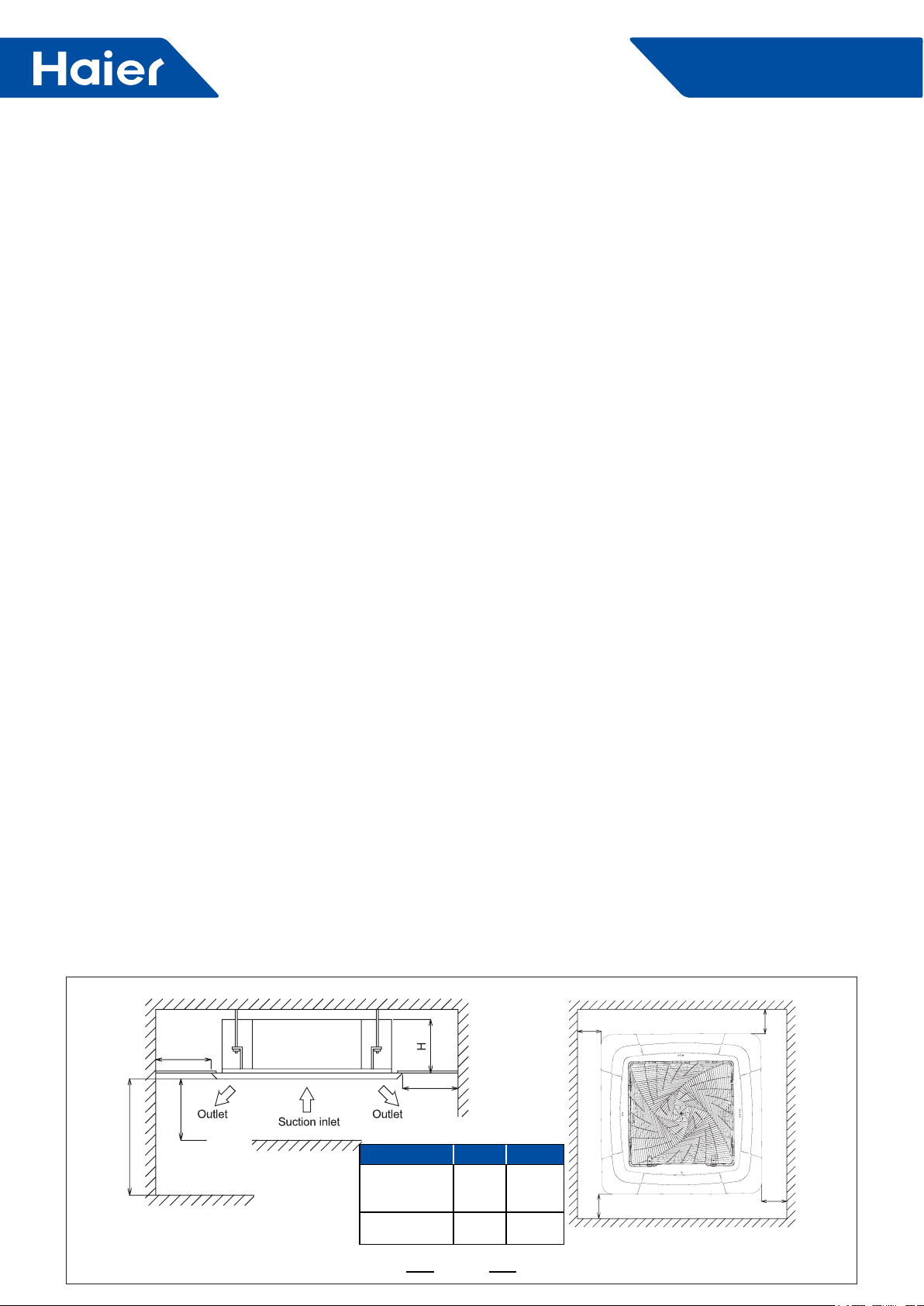
≥1500
I
≥1500
Space required for installation (unit: mm)
≥1500
Model H(mm) I(m)
ABH071H1ERG
ABH090H1ERG
ABH105H1ERG
ABH125K1ERG
ABH140K1ERG
246 2.5≤I≤3.5
288 2.5≤I≤4.2
24
≥1500
≥1500
≥1500
≥1500
Smart Power
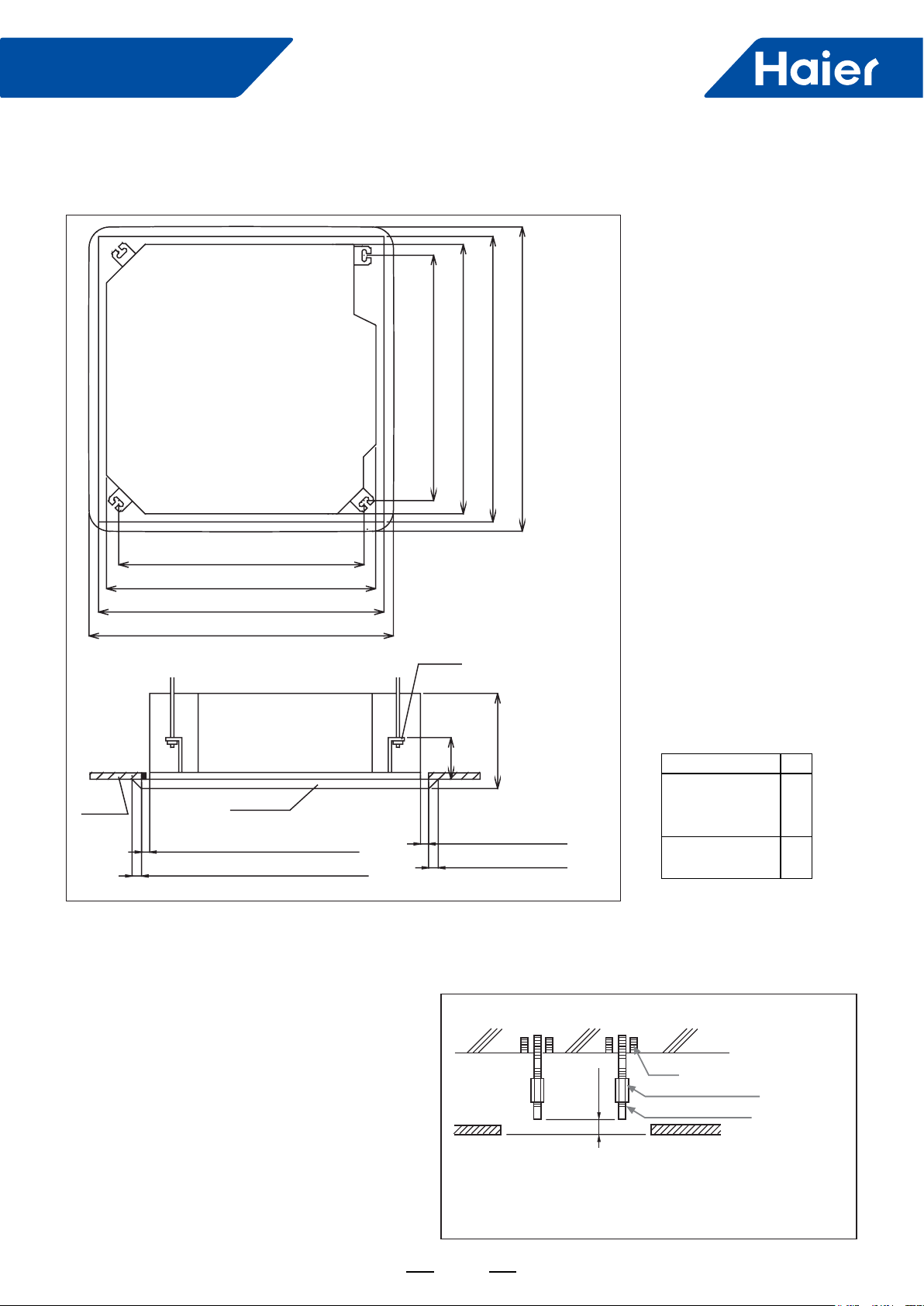
7.3 Preparation before installation
(1) Location relationships between ceiling opening and hanging screw
Ceiling
765 (Spacing of hanging screw)
850 (Indoor unit)
890 (Ceiling opening)
950 (Trim panel)
Trim panel
Distance between indoor unit and
ceiling≤20
Overlap between ceiling and trim
panel≥30
850 (Indoor unit)
765 (Spacing of hanging screw)
Hanger bracket
130
Distance between indoor
unit and ceiling≤20
Overlap between ceiling
and trim panel≥30
950 (Trim panel)
890 (Ceiling opening)
H
Model H
ABH071H1ERG
ABH090H1ERG
ABH105H1ERG
ABH125K1ERG
ABH140K1ERG
299
341
Note:
Overlap between the ceiling and decorative panel shall be 30mm or more. The distance between indoor unit and
ceiling shall be 20mm or less. If it’s more than 20mm, add ceiling materials at or repair the ceiling.
(2) Complete all pipes (for refrigerants and drainage)
and wires (for connection of indoor and outdoor
units) to be connected to indoor unit before
installation so that they can be connected to indoor
unit immediately after installation.
(3) Install hanging screws
• To bearing the unit weight, use foundation bolts on
existing ceilings, or embedded bolts, buried bolts or
other parts that is provided on site on new ceilings.
Before installation is continued, adjust the distance
from ceiling.
Note:
All the above parts are to be provided on installation sites.
Diameter of hanging screws is M10.
25
<Installation example>
Bolt
Long nut or threaded coupling
50-80mm
Hanging screw (M10)
Ceiling
Roof slab
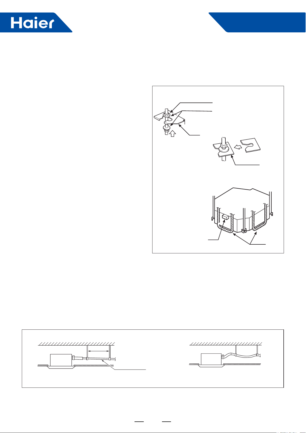
7.4 Installation of indoor unit
Installation sequence on new ceiling: (1) → (3) → (4) → (5)
(1) Temporary installation of indoor unit
• Attach hangers to hanging screws, and make sure to
use nuts and washers on both upper and lower ends of
hangers so as to x them rmly. A washer xing plate
(to be provided on site) can prevent the washer from
dropping off.
<Work at ceilings>
(2) Adjust units to appropriate installation locations.
Refer to "7.3 Preparation before installation."
Tighten (double nuts)
[secure hanger]
Smart Power
Nut (to be provided on site)
Washer (to be provided on site)
Hanger
Insert
(3) Correct levelness of air conditioner units.
• The indoor unit is equipped with a built-in drainage
pump and a oat switch. Correct levelness with a level
or water-lled polyethylene pipe.
Washer xing plate
(to be provided on site)
[secure the washer]
Note:
If the unit inclines towards reverse direction of
condensate ow, the oat switch can not work normally
and water leakage will be resulted.
(4) Pull out the original xing plate that prevents the
washer from dropping off, and tighten nuts.
(5) Remove the installation cardboard.
7.5 Installation of drain pipe
(1) Install drain pipe
• Diameter of the drain pipe shall be greater than or equal to that of the connecting pipe.
(PE pipe: size: I.D.: 25mm; O.D.: 32mm)
• The drain pipe shall be short and have a downward slope of at least 1/100 to prevent pockets.
• If it is impossible to provide sufcient slope to the drain pipe, a drain lift pipe shall be installed.
• To avoid bending of the drain pipe, hangers shall be kept 1-1.5m away from each other.
Level
Polythene pipe
Correct
1-1.5m
Slope over 1/100
Wrong
26
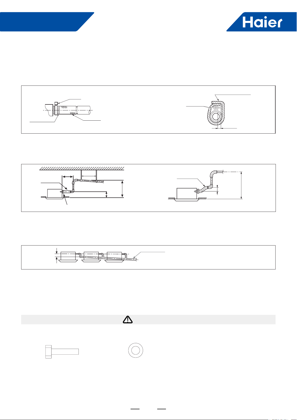
Smart Power
Use a drain hose and clamp.
Insert the drain hose into the drainage outlet until it reaches the white tape. Then tighten the clamp.
For heat insulation, wind the drain hose with sealing gaskets. Provide heat insulation to indoor drain hose.
Clamp
Clamp (accessory)
Tape (White)
<Precautions for drain lift pipe>
The drain lift pipe shall be installed as low as possible.
The drain lift pipe shall be perpendicular to the unit and not more than 300mm away from the unit.
In 300mm 1-1.5m
Drain hose
Clamp
Drain hose
Hanger
202mm
Large-size sealing gasket (accessory)
Below 4mm
Drain hose
75 below
500 below
Note:
• The slope of accessory drain pipe shall be within 75mm so that the drainage outlet does not necessarily bear
excessive external force.
• If multiple drain pipes join together, install them as follows.
T-joint conuent drain pipe
Above
100mm
The size of conuent drain pipe selected shall be suitable for operating capacity of the units.
(2) Check drainage is smooth after installation.
• Check drainage by lling in 1200cc water slowly from air outlet or inspection hole.
7.6 Installation instruction for embedded air-conditioning panel
1. Before installation
WARNING
The trim panel shall be put on buffer materials when unpacked to prevent being scratched by hard objects.
Please conrm the following accessories delivered with the product:
Bolt (M5*25) Qty: 4 Gasket Qty: 4
27
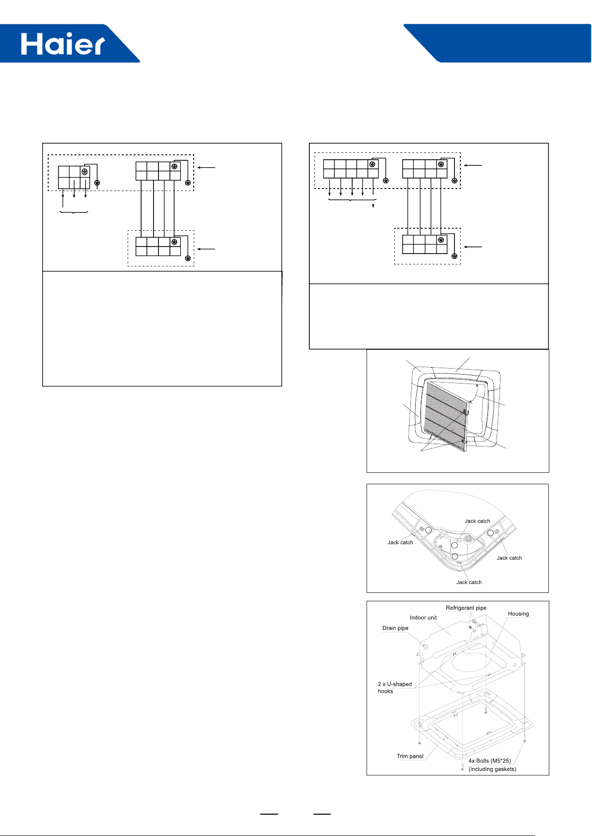
Connect and x the power supply cable, indoor-outdoor connection cable as following:
Smart Power
L N
Power supply:
1PH, 220-240V~,
50/60Hz
3
2
1
3
2
1
Outdoor unit
terminal blocks
Indoor unit
R S T N
Power supply:
380-415V, 3N~,
50/60Hz
terminal blocks
Power supply cable:
1UH071N1ERG, 1UH090N1ERG, 1UH105N1ERG:
H05RN-F 3G 4.0mm
1UH125P1ERG, 1UH140P1ERG:
H05RN-F 3G 6.0mm
Indoor and outdoor connection cable: H05RN-F 4G
2.5mm
2
2
2
For three phase power supply models:
1UH125P1ERK, 1UH140P1ERK
Power supply cable: H05RN-F 5G 4.0mm
Indoor and outdoor connection cable: H05RN-F 4G
2.5mm
2
2. Installation
(1) Conrming the position of unit hanger
Please conrm the installation position of the hanger for indoor unit
is about 130mm above the ceiling. For details, please refer to the
Instructions for Installation and Maintenance of indoor unit.
(2) Removing the air-inlet grille
Open the air-inlet grille to make it at an angle of 45° to the trim
panel. As shown in the following gure, please remove the air-inlet
grille as per the operation requirements.
(3) Installing the panel
1) Please remove the four (4) angle trim panels. Removal method: Flip
the jack catches of the angle trim panel in the order of
①②③④
, as
shown in the following gure. The ipping direction is indicated by the
arrows. Then the angle trim panel can be removed.
2) Pull out the two (2) U-shaped hooks on the indoor unit from below.
3) Adjust the panel direction to make the angle side engraved with "Pipe
side" consistent with the refrigerant pipe of the indoor unit, and make
the angle side engraved with "Drain side" consistent with the drain
side of the indoor unit. Then hang the 2 hooks in the inner side of the
panel on the 2 U-shaped hooks of the indoor unit.
4) Finally x the panel on the indoor unit with the bolts (M5*25) and
gaskets delivered with the unit.
Caution: Gaskets must be used for xing, or else the panel would be
easy to fall off.
5) When tightening the four (4) bolts, please make sure there is no
clearance between the panel xing seat on the side of the indoor
unit and the panel xing seat on the side of the panel. That is to say:
the bolts shall be fully tightened (see * in the gure) . If there is a
clearance, air leakage or water leakage is likely to occur.
3
2
1
3
2
1
Outdoor unit
terminal blocks
Indoor unit
terminal blocks
2
1
3
4
2
28

Smart Power
CAUTION
• Improper tightening of bolts would lead to the faults shown in
the following gure.
• After tightening the bolts, if there is a clearance between the
ceiling and the trim panel, please readjust the height of the
indoor unit.
If the elevation level of the indoor unit and drain pipe are not
affected, you can adjust the height of the indoor unit through the
corner pore on the trim panel. Please keep the unit horizontal
in the process of adjustment, or else water leakage is easy to
occur.
• Please do not swing the louver blade by hand, or else the
blade mechanism would be damaged.
6) Connection of trim panel. Connect the black lead-out terminal
of the panel to the black lead-out terminal of the indoor unit
housing.
7) When the installation of panel is complete, please x the four
(4) angle trim panels.
• Hang and tighten the strap of the angle trim panel on the
shackle of the trim panel, as shown in the gure.
• Fix the angle trim panel on the trim panel.
29

8) Installing the air-inlet grille.
Install the air-inlet grille with the steps opposite to that
for removing.
For reference
The method for removing angle trim panels when the
installation of trim panel is complete:
1) Insert a straight screwdriver in the notch① . Gently
turn the screwdriver downward, and slowly insert it in,
and then move it up and down to make the angle fall
off.
2) Make the angle②and③fall off in the same way.
3) Take off the angle trim panel by hand.
8. Test run
8.1 Check items
1. Indoor unit
• Is operation of each button on the remote control unit normal?
• Does each lamp light normally?
• Do not air ow direction louvers operate normally?
• Is the drain normal?
Smart Power
¢
¢
¢
2. Outdoor unit
• Is there any abnormal noise and vibration during operation?
• Will noise, wind, or drain water from the unit disturb the neighbors?
• Is there any gas leakage?
Customer guidance
Explain the following to the customer in accordance with the operation manual:
(1) Starting and stopping method, operation switching, temperature adjustment, timer, air ow switching, and other
remote control unit operations.
(2) Air lter removal and cleaning, and how to use air louvers.
(3) Give the operation and installation manuals to the customer.
8.2 Test run
This unit will be started instantly without "ON" operation when electric power is supplied. Be sure to execute "OFF"
operation before electric power is disconnected for servicing.
• This unit has a function of automatic restart system after recovering power stoppage
1. Before starting test run (for Heat pump models)
Conrm whether the power source breaker (main switch) of the unit has been turned on for over
12 hrs to energize the crankcase heater in advance of operation.
2. Test run
• Run the unit continuously for about 30 minutes, and check the following. Suction pressure at check joint of service
valve for gas pipe.
• Discharge pressure at check joint on the compressor discharge pipe.
• Temperature difference between return air and supply air for indoor unit.
30

Smart Power
Part 3 Indoor Units-Medium ESP Duct Type
1. Feature ..................................................................................................................................................................32
2. Specication ..........................................................................................................................................................34
3. Dimension..............................................................................................................................................................41
4. Wiring Diagram ......................................................................................................................................................43
5. Airow and Static Pressure Chart ..........................................................................................................................46
6. Instalaltion .............................................................................................................................................................49
7. Sound Pressure Level ...........................................................................................................................................58
31

1. Feature
250
250
mm
High Effciency
DC fan motor
Haier duct adopts DC fan motor, compared to conventional
AC fan motor, DC fan motor is more effciency.
Torque(kgfcm)
100
80
60
40
25%
35%
40%
Smart Power
Torque(kgfcm)
100
80
60
40
85%
87.5%
90%
Comfortable
Consistent airflow
The indoor units contain up to 3 fans which can provide
consistent airow in different ESP enhancing the comfort.
Flexible Design
Super slim
250mm of thickness for better installation application fexibility.
20
0
200 400 600 800 1000
Rev(r/min)
20
0
200 400 600 800 1000
AC motor efficiency DC motor efficiency
120Pa
100Pa
70Pa
50Pa
Air Flow
2500
m/h³
2500
100%
2000
1500
50po 70po 100po 120po
Common
Air Flow
2500
2500
m/h³
100%
2000
1500
50po 70po 100po 120po
m/h³
2500
2500
100%
100%
2250
m/h³
90%
1900
250
Rev(r/min)
m/h³
2500
m/h³
76%
1700
mm
100% airflow when the ESP
m/h³
100%
reach 120pa for Haier duct
ESP
Oniy 68% airflow when the ESP
reach 120pa for traditional duct
m/h³
68%
ESP
Return air choices
Friendly design: Rear air return or bottom air return
is available.
Rear air return
Bottom air return
32

Smart Power
High lift-up drain pump
It can lift condensed water up to 750mm, which make
installation more exible according to the layout.
Adjustable E.S.P control
Because of the DC fan motor, the duct unit can adjust
E.S.P :10/30/50/70Pa(7.1kW,8.2kW), 30~120Pa
(10,12.5,14kW) by the wired controller, it can optimise air
duct work installation, maintain airow and sound levels
as required.
H
Air volume
M
L
Max.
750mm
H
M
L
External Statlc Pressure(E.S.P)
E.S.P setting(Pa) 30 40 50 60 70 80 90 100 110 120
33

Smart Power
2. Specication
Item Model ADH071M1ERG/1UH071N1ERG
Function Cooling Heating
Capacity
Sensible heat ratio
Total power input
Max. power input
AEER or ACOP Dehumidifying capacity
Connection cable( from outdoor to indoor)
Power source
Running/Max.
Running current Start current
Circuit breaker
Unit model (color) ADH071M1ERG
Type×Number CENTRIFUGALX2
Speed (H-M-L)
Fan
Fan motor output/ input power
Air-ow (H-M-L)
External static pressure
Type / Diameter
Row 3
Total area
External (L×W×H)
Package (L×W×H)
Indoor
unit
Heat
exchanger
Dimension
Drainage pipe (material, I.D./O.D.)
Controller (O-Optional, S-Standard)
Fresh air hole dimension
Electricity heater
Sound power noise level (H)
Sound pressure noise level (H-M-L)
Weight (Net/Shipping)
Refrigerant
Type / Charge g R410A/2500
Recharge quantity g/m 45
Liquid m 9.52
Gas mm 15.88
Max.pipe lengh without
Piping
Pipe
charge refrigerant
Between
I.D &O.D
MAX.Drop m 30
MAX.Piping length m 50
Connecting method Flared
Cooling Pdesignc (kW): 7.1kW SEER/CLASS 6.3/A++
Average Pdesignh (-10°C) 6.0kW SCOP/CLASS
Heating
Warmer Pdesignh (2°C) 6.0kW SCOP/CLASS
Colder Pdesignh (-22°C) / SCOP/CLASS
Tdesignh: -10°C Tbivalent: -10°C TOL: -15°C Elbu: 0
Max. cooling
condition
Indoor temperature: 32°C/23°C
Outdoor temperature: 46°C/-°C Outdoor temperature: 24C/18C
Max. heating condition
Norminal condition:
Indoor temperature (cooling) : 27DB (°C)/19WB (°C) , Indoor temperature (heating) : 20DB (°C)
Outdoor temperature (cooling) : 35DB (°C)/24WB (°C) , Outdoor temperature (heating) : 7DB (°C)/6WB (°C)
The noise level will be measured in the third octave band limited values, using a Real Time Analyser calibrated sound intensity
meter. It is a sound pressure noise level.
kW
7.1 (2.0~9.0) 8 (2.0~10.0)
0.72 /
10
kW
W
W/W
-3×m3
/h
2.03 (0.4~4.0) 2.0 (0.4~4.0)
4000 4000
3.41 3.89
N, V, Hz
A/A
8.8 (2.0-17.5) /17.5 9.2 (2.0-17.5) /17.5
A
A
1ph,30A (from outdoor)
r/min
W
3
m
/h
Pa
mm
m
2
Inner grooved pipe/φ7.0
mm×mm×mm
mm×mm×mm
mm
Wired
YR-E16A(O)/YR-E17(S)
Infrared
mm
kW
dB (A)
dB (A)
kg / kg
mm 20
QCE(Annual electricity
consumption for cooling)kWh:
4.2/A+
4.8/A++
QHE(Annual electricity
consumption for heating)kWh:
/
Indoor temperature: 27°C/-°C
H05RN-F 4G 2.5mm2
2
4.0mm
1, 220-240, 50/60
3
950/860/760
85/111
1050/840/630
10/30(default)/50/70
7.668
957/655/250
1170/860/340
PVC 25/29
YR-HBS01(O)
145
/
58
38/35/32
31.2/36.8
390
1982
1652
/
34

Smart Power
Item Model ADH071M3ERG/1UH071N1ERG
Function Cooling Heating
Capacity kW 7.1(2.0~9.0) 8(2.0~10.0)
Sensible heat ratio 0.72 /
Total power input kW 2.03(0.4~4.0) 2.0(0.4~4.0)
Max. power input W 4000 4000
AEER or ACOP W/W 3.41 3.89
Dehumidifying capacity 10
Power cable 4.0mm
Power source N, V, Hz 1, 220~240, 50/60
Running/Max. Running current A/A
Start current A 0.52
Circuit breaker A
Unit model (color)
Type×Number
Speed (H-M-L) r/min
Fan
Fan motor output/ input power kW
Air-ow (H-M-L) m
External static pressure Pa
Type/Diameter mm
Total area m
External (L×W×H) mm×mm×mm 957/655/250
Package (L×W×H) mm×mm×mm 1170/860/340
Indoor
unit
Heat
exchanger
Dimension
Drainage pipe (material, I.D./O.D.) mm PVC 25/29
Controller (O-Optional, S-Standard)
Fresh air hole dimension mm 145
Electricity heater kW /
Sound power noise level (H) dB (A) 58
Sound pressure noise level (H) dB (A) 38/35/32
Weight (Net / Shipping) kg / kg 31.2/36.8
Refrigerant
Type / Charge g R410A/2500
Recharge quantity g/m 45
Liquid mm 9.52
Gas mm 15.88
Max.pipe lengh without
Piping
Pipe
charge refrigerant
Between
I.D&O.D
MAX.Drop m 30
MAX.Piping length m 50
Connecting method Flared
Cooling Pdesignc (kW): 7.1kW SEER/CLASS 6.3/A++
Average Pdesignh (-10°C) 6.0kW SCOP/CLASS
Heating
Warmer Pdesignh (2°C) 6.5kW SCOP/CLASS
Colder Pdesignh (-22°C) / SCOP/CLASS
Tdesignh: -10°C Tbivalent: -10°C TOL: -15°C Elbu: 0
Max. cooling
condition
Indoor temperature: 32°C/23°C
Outdoor temperature: 46°C/-°C Outdoor temperature: 24C/18C
Norminal condition:
Indoor temperature (cooling) : 27DB (°C)/19WB (°C) , Indoor temperature (heating) : 20DB (°C)
Outdoor temperature (cooling) : 35DB (°C)/24WB (°C) , Outdoor temperature (heating) : 7DB (°C)/6WB (°C)
The noise level will be measured in the third octave band limited values, using a Real Time Analyser calibrated sound intensity
meter. It is a sound pressure noise level.
-3×m3
/h 2.4
2
8.8(2.0-17.5)/17.5 9.2(2.0-17.5)/17.5
1Ph,30A(from outdoor)
ADH071M3ERG
CENTRIFUGALX2
1050/950/850/750
0.27/0.2
3
/h
1450/1200/950/700
25/37/50/70/90/100/110/120/130/150
Inner grooved pipe/φ7.0
2
7.668
Wired YR-E16A(O)/YR-E17(S)
Infrared YR-HBS01 (O)
20
QCE(Annual electricity
consumption for cooling)kWh:
4.2/A+
4.8/A++
Max. heating condition
QHE(Annual electricity
consumption for heating)kWh:
/
Indoor temperature: 27°C/-°C
390
1982
1652
/
35

Smart Power
Item Model ADH090M1ERG/1UH090N1ERG
Function Cooling Heating
Capacity kW 8.5 (2.5~10) 9.5 (2.5~11)
Sensible heat ratio 0.72 /
Total power input kW 2.50 (0.5~4.4) 2.50 (0.5~4.4)
Max. power input W 4400 4400
AEER or ACOP W/W 3.33 3.72
Dehumidifying capacity 10
Power cable 4.0mm
Power source N, V, Hz 1, 220-240, 50/60
Running/Max. Running current A/A
Start current A 3
Circuit breaker A
Unit model (color) ADH090M1ERG
Type×Number CENTRIFUGALX2
Speed (H-M-L) r/min 1020/920/820
Fan
Fan motor output/ input power W 112/147
Air-ow (H-M-L) m
External static pressure Pa 10/30(default)/50/70
Type/Diameter mm Inner grooved pipe/φ7.0
Row 3
Total area m
External (L×W×H) mm×mm×mm 957/655/250
Package (L×W×H) mm×mm×mm 1170/860/340
Indoor
unit
Heat
exchanger
Dimension
Drainage pipe (material, I.D./O.D.) mm PVC 25/29
Controller (O-Optional, S-Standard)
Fresh air hole dimension mm 145
Electricity heater kW NONE
Sound power noise level (H) dB (A) 60
Sound pressure noise level (H-M-L) dB (A) 40/37/34
Refrigerant
Type / Charge g R410A/2500
Recharge quantity g/m 45
Liquid mm 9.52
Gas mm 15.88
Max.pipe lengh without
Piping
Pipe
charge refrigerant
Between
I.D &O.D
MAX.Drop m 30
MAX.Piping length m 50
Connecting method Flared
Cooling Pdesignc (kW): 8.5kW SEER/CLASS 6.1/A++
Average Pdesignh (-10°C) 7.0kW SCOP/CLASS
Heating
Warmer Pdesignh (2°C) 7.8kW SCOP/CLASS
Colder Pdesignh (-22°C) / SCOP/CLASS
Tdesignh: -10°C Tbivalent: -10°C TOL: -15°C Elbu: 0
Max. cooling
condition
Indoor temperature: 32°C/23°C
Outdoor temperature: 46°C/-°C Outdoor temperature: 24C/18C
Norminal condition:
Indoor temperature (cooling) : 27DB (°C)/19WB (°C) , Indoor temperature (heating) : 20DB (°C)
Outdoor temperature (cooling) : 35DB (°C)/24WB (°C) , Outdoor temperature (heating) : 7DB (°C)/6WB (°C)
The noise level will be measured in the third octave band limited values, using a Real Time Analyser calibrated sound intensity
meter. It is a sound pressure noise level.
-3×m3
/h 2.5
2
11.1 (2.3-19.2) /19.2 11.1 (2.3-19.2) /19.2
1Ph,30A(from outdoor)
3
/h 1300/900/700
2
/
Wired YR-E16A(O)/YR-E17(S)
Infrared YR-HBS01(O)
m 20
QCE(Annual electricity
consumption for cooling)kWh:
4.1/A+
4.8/A++
Max. heating condition
QHE(Annual electricity
consumption for heating)kWh:
/
Indoor temperature: 27°C/-°C
485
2256
1928
/
36

Smart Power
Item Model ADH105M1ERG/1UH105N1ERG
Function Cooling Heating
Capacity kW 10 (2.5~11) 10.4 (2.5~12)
Sensible heat ratio 0.72 /
Total power input kW 2.93(0.5~4.5) 2.97 (0.5~4.5)
Max. power input W 5000 5000
AEER or ACOP W/W 3.37 3.46
Dehumidifying capacity 10
Power cable 4.0mm
Power source N, V, Hz 1, 220~240, 50/60
Running/Max. Running current A/A
Start current A 3
Circuit breaker A
Unit model (color)
Type×Number
Speed (H-M-L) r/min
Fan
Fan motor output/ input power kW
Air-ow (H-M-L) m
External static pressure Pa
Type/Diameter mm
Total area m
External (L×W×H) mm×mm×mm 1500/700/250
Package (L×W×H) mm×mm×mm 1710/865/320
Indoor
unit
Heat
exchanger
Dimension
Drainage pipe (material, I.D./O.D.) mm PVC 26/32
Controller (O-Optional, S-Standard)
Fresh air hole dimension mm 100
Electricity heater kW /
Sound power noise level (H) dB (A) 55
Sound pressure noise level (H) dB (A) 32/28/25/23
Weight (Net / Shipping) kg / kg 49/61
Refrigerant
Type / Charge g R410A/2500
Recharge quantity g/m 45
Liquid mm 9.52
Gas mm 15.88
Max.pipe lengh without
Piping
Pipe
charge refrigerant
Between
I.D&O.D
MAX.Drop m 30
MAX.Piping length m 50
Connecting method Flared
Cooling Pdesignc (kW): 10kW SEER/CLASS 6.7/A++
Average Pdesignh (-10°C) 9.7kW SCOP/CLASS
Heating
Warmer Pdesignh (2°C) 10.2kW SCOP/CLASS
Colder Pdesignh (-22°C) / SCOP/CLASS
Tdesignh: -10°C Tbivalent: -10°C TOL: -15°C Elbu: 0
Max. cooling
condition
Indoor temperature: 32°C/23°C
Outdoor temperature: 46°C/-°C Outdoor temperature: 24C/18C
Norminal condition:
Indoor temperature (cooling) : 27DB (°C)/19WB (°C) , Indoor temperature (heating) : 20DB (°C)
Outdoor temperature (cooling) : 35DB (°C)/24WB (°C) , Outdoor temperature (heating) : 7DB (°C)/6WB (°C)
The noise level will be measured in the third octave band limited values, using a Real Time Analyser calibrated sound intensity
meter. It is a sound pressure noise level.
-3×m3
/h 3.2
2
13.3 (2.3-19.0) /21.0 13.5 (2.3-19.0) /21.0
1Ph,
40A (from outdoor)
ADH105M1ERG
CENTRIFUGALX3
1050/950/850
0.16/0.2
3
/h
2000/1740/1380/1280
30-120
Inner grooved pipe/φ7.0
2
/
Wired YR-E16A(O)/YR-E17(S)
Infrared YR-HBS01 (O)
20
QCE(Annual electricity
consumption for cooling)kWh:
4.0/A+
4.8/A++
Max. heating condition
QHE(Annual electricity
consumption for heating)kWh:
/
Indoor temperature: 27°C/-°C
548
3624
2976
/
37

Smart Power
Item Model ADH125M1ERG/1UH125P1ERG
Function Cooling Heating
10
kW
kW
W
W/W
-3×m3
/h
12.5 (3.5~15.0) 13.7(4~18.0)
3.67 (1.0~6.5) 3.91 (1.0~6.5)
6500 6500
3.37 3.47
N, V, Hz
17.0 (8.7-30.0) /30A 17.5 (8.7-30.0) /30A
A
A
r/min
kW
3
m
/h
Pa
mm
2
m
mm×mm×mm
mm×mm×mm
mm
Wired
Infrared
mm
kW
dB (A)
dB (A)
kg / kg
g
g/m
m 30
4.9
2
1ph, 220~240, 50/60
3
40
1100/1000/950
0.32/0.4
2250/1960/1680
30-120
Inner grooved pipe/φ7.0
/
1500/700/250
1710/865/320
PVC 26/32
YR-E17 (S)/YR-E16A(O)
YR-HBS01 (O)
125
/
62
39/36/33/31
52/62
R410A/3700
45
Capacity
Sensible heat ratio 0.74 /
Total power input
Max. power input
AEER or ACOP
Dehumidifying capacity
Power cable 6.0mm
Power source
Running/Max. Running current A/A
Start current
Circuit breaker
Unit model (color) ADH125M1ERG
Type×Number CENTRIFUGALX3
Speed (H-M-L)
Fan
Fan motor output power/input power
Air-ow(H-M-L)
ESP
Type/Diameter
Total area
External (L×W×H)
Package (L×W×H)
Indoor
unit
Heat
exchanger
Dimension
Drainage pipe (material, I.D./O.D.)
Controller (O-Optional, S-Standard)
Fresh air hole dimension
Electricity heater
Sound power noise level (H)
Sound pressure noise level (H-M-L)
Weight (Net / Shipping)
Refrigerant
Type / Charge
Recharge quantity
Liquid mm 9.52
Gas mm 15.88
Max.pipe lengh without
Piping
Pipe
charge refrigerant
Between
I.D&O.D
MAX.Drop m 30
MAX.Piping length m 75
Connecting method Flared
Norminal condition:
Indoor temperature (cooling) : 27DB (°C)/19WB (°C) , Indoor temperature (heating) : 20DB (°C)
Outdoor temperature (cooling) : 35DB (°C)/24WB (°C) , Outdoor temperature (heating) : 7DB (°C)/6WB (°C)
The noise level will be measured in the third octave band limited values, using a Real Time Analyser calibrated sound intensity
meter. It is a sound pressure noise level.
38

Smart Power
Item Model ADH125M1ERG/1UH125P1ERK
Function Cooling Heating
Capacity kW 12.5 (3.5~15.0) 13.7(4~18.0)
Sensible heat ratio 0.74 /
Total power input kW 3.67 (1.0~6.5) 3.91 (1.0~6.5)
Max. power input W 7000 7000
AEER or ACOP W/W 3.37 3.47
Dehumidifying capacity 10
Power cable 4.0mm
Power source N, V, Hz 3, 380~415, 50/60
Running/Max. Running current A/A
Start current A 3
Circuit breaker A
Unit model (color) ADH125M1ERG
Type×Number CENTRIFUGALX3
Speed (H-M-L) r/min 1200/1050/900
Fan
Fan motor input power/output power kW 0.32/0.4
Air-ow (H-M-L) m
ESP Pa 30-120
Type/Diameter mm Inner grooved pipe/φ7.0
Total area m
External (L×W×H) mm×mm×mm 1500/700/250
Package (L×W×H) mm×mm×mm 1710/865/320
Indoor
unit
Heat
exchanger
Dimension
Drainage pipe (material, I.D./O.D.) mm PVC 26/32
Controller (O-Optional, S-Standard)
Fresh air hole dimension mm 125
Electricity heater kW /
Sound power noise level (H) dB (A) 62
Sound pressure noise level (H-M-L) dB (A) 39/36/33/31
Weight (Net / Shipping) kg / kg 52/62
Refrigerant
Pipe
Piping
Type / Charge g R410A/3700
Recharge quantity g/m 45
Liquid mm 9.52
Gas mm 15.88
Max.pipe lengh without
charge refrigerant
Between
I.D&O.D
MAX.Drop m 30
MAX.Piping length m 75
Connecting method Flared
-3×m3
/h 4.9
2
6.1/10.8 6.5/10.8
3Ph,40A (from outdoor)
3
/h 2250/1960/1680/1500
2
/
Wired YR-E17(S)/YR-E16A(O)
Infrared YR-HBS01 (O)
m 30
Norminal condition:
Indoor temperature (cooling) : 27DB (°C)/19WB (°C) , Indoor temperature (heating) : 20DB (°C)
Outdoor temperature (cooling) : 35DB (°C)/24WB (°C) , Outdoor temperature (heating) : 7DB (°C)/6WB (°C)
The noise level will be measured in the third octave band limited values, using a Real Time Analyser calibrated sound intensity
meter. It is a sound pressure noise level.
39

Smart Power
Item Model ADH140M1ERG/1UH140P1ERK
Function Cooling Heating
Capacity kW 13.4 (3.5~16) 15.0 (4.0~19.0)
Sensible heat ratio 0.74 /
Total power input kW 4.05 (1.0~6.5) 4.29 (1.2~6.5)
Max. power input W 7200 7200
AEER or ACOP W/W 3.27 3.47
Dehumidifying capacity 10
Power cable 4.0mm
Power source N, V, Hz 3,380~415, 50/60
Running/Max. Running current A/A
Start current A 3
Circuit breaker A
Unit model (color) ADH140M1ERG
Type×Number CENTRIFUGALX3
Speed (H-M-L) r/min 1250/1120/900
Fan
Fan motor input power/output power kW 0.32/0.4
Air-ow (H-M-L) m
ESP Pa 30-120
Type/Diameter mm Inner grooved pipe/φ7.0
Total area m
External (L×W×H) mm×mm×mm 1500/700/250
Package (L×W×H) mm×mm×mm 1710/865/320
Indoor
unit
Heat
exchanger
Dimension
Drainage pipe (material, I.D./O.D.) mm PVC 26/32
Controller (O-Optional, S-Standard)
Fresh air hole dimension mm 125
Electricity heater kW /
Sound power noise level (H) dB (A) 64
Sound pressure noise level (H-M-L) dB (A) 41/36/33
Weight (Net / Shipping) kg / kg 52/63
Refrigerant
Type / Charge g R410A/3700
Recharge quantity g/m 45
Liquid mm 9.52
Gas mm 15.88
Max.pipe lengh without
Piping
Pipe
charge refrigerant
Between
I.D&O.D
MAX.Drop m 30
MAX.Piping length m 75
Connecting method Flared
Norminal condition:
Indoor temperature (cooling) : 27DB (°C)/19WB (°C) , Indoor temperature (heating) : 20DB (°C)
Outdoor temperature (cooling) : 35DB (°C)/24WB (°C) , Outdoor temperature (heating) : 7DB (°C)/6WB (°C)
The noise level will be measured in the third octave band limited values, using a Real Time Analyser calibrated sound
intensity meter. It is a sound pressure noise level.
-3×m3
/h 5.2
2
6.8(2.9-10.5)/11.0 7.0(2.9-10.5)/11.0
3Ph,40A (from outdoor)
3
/h 2500/2160/1780
2
/
Wired YR-E17(S)/YR-E16A (O)
Infrared YR-HBS01 (O)
m 30
40

Smart Power
3. Dimension
3.1 ADH071M1ERG ADH071M3ERG ADH090M1ERG
air inlet
air outlet
41

3.2 ADH105M1ERG AD1H125M1ERG ADH140M1ERG
Smart Power
return air
supply air
42

Smart Power
4. Wiring Diagram
ADH071M1ERG ADH090M1ERG
0150519911
REMOTE RECEIVER
CONNECT TO THIRD PARTY RELAY
RATING_12VDC
ELECTRIC HEATING TERMINAL
B:BLACK
R:RED
W:WHITE
Y/G:YELLOW/GREEN
ROOM
FLOAT
SWITCH
WIFI
ROOMCARD
SENSOR
TEMP.
CN29
CN5
CN19
87654321
CN18
4321
CN7
CN36
CN6
CN13
CN15
CN16
OFF
ON
SW1
SW2
ON
OFF
FUSE
CN22
CN8
T5A/250VAC
C
B A
CN23
CN1
CN14
CN9
CH2
M
PUMP
CN37
CH3
CN4
CH1
C
B
A
WIRED
Y/G
R
3
2
B
1
W
CONTROLLER
TO OUT DOOR
Static
pressure
1st level
OFF
SW1-5
OFF
SW1-4
Type define
Medium ESP DUCT
OFF
SW1-8
ON
SW1-7
Room card
available
unavailable
ON
OFF
SW1-6
4th level
3rd level
2nd level
ON
OFF
ON
ON
OFF
ON
PIPING TEMP.
SENSOR
R O T O M N A F C D
M
NOTE:
USER SHOULD NOT SET SW1
1.DASHED PARTS ARE
OPTIONAL.
2.
AND SW2 WITHOUT GUIDENCE.
3.THE BRIDGE (CN22 CN23) ON SLAVE
UNITS PCB SHOULD BE CUT OFF WHEN
43
7.1
9.0
CAPACITY
(KW)
ON OFF ON
OFF ON ON
/ / /
/
SW1-3
SW1-2
SW1-1
ONE WIRED CONTROLLER CONTROL MORE
THAN ONE UNIT.
4.REFER TO INSTALLATION MANULTO
GET MUCH MORE DETAILS ABOUT THE
STATIC PRESSURE LEVEL SELECTION.

ADH071M3ERG
Smart Power
ROTOM NAF CD
0150523302
M
CN6
CN21
PUMP
M
CN4
ON
OFF
SW03
12345678
CN41
M
CN5
ROOM
FRESH AIR MOTOR
(SW01-6 select OFF) /
EXTERNAL ALARM OUTPUT
(SW01-6 select ON)
( Contact rating_230VAC,3A)
CH1
CH2
Heater_N
3
2
CN1
1
N L S
FUSE
TO OUT DOOR
CH4
SENSOR
TEMP.
MODEL
FOR ALL DUCTED
MODEL
AD71S2SM1FA
Y/G:YELLOW/GREEN
SW01-8
SW03-8
SW03-7
Y/G
OFF
OFF
SW01-7
OFF
SW01-6
3
OFF
SW03-4 SW03-5 SW03-6
SW03-3
SW03-2
OFF OFF OFF OFF OFF OFF OFFON
SW03-1
SW01-5
SW01-4
OFF
SW01-3
ON
SW01-2
ON
SW01-1
OFF
2
1
AM24LP2VHA
OFF
OFF
OFF
OFF
OFF
ON
ON
AD50S2SM1FA
ADH071M3ERG
ON
ON
OFF
OFF OFF
OFF
OFF
OFF
OFF
OFF
ON
ON
OFF
OFF
ON
OFF
OFF
REMOTE RECEIVER
CN34
WIFI
MODULE
ROOMCARD
SW01
12345678
ON
OFF
CN16
FLOAT
SWITCH
PIPING
CN13
SENSOR
TEMP.
Heater_L
A
B
C
CN22
B A
C
CN22-1
B A
C
CONTROLLER
WIRED
NOTE:
1.DASHED PARTS ARE OPTIONAL.
2.SW03-4 IS AT ON POSITION,DO NOT CHANGE
THE SETTINGS OF SWITCHS WITHOUT GUIDANCE.
3.WHEN ONE WIRED CONTROLLER CONTROL MULTIPLE INDOOR UNIT,
IT CAN CONNECT ANOTHER INDOOR UNIT BY CN22 OR CN22-1.
WHEN TWO WIRD CONTROLLERS CONTROL ONE INDOOR UNIT,
THE WIRED CONTROLLER NEED CONNECT WITH CN22 AND CN22-1.
ADDRESS SETTING ON THE
->SW03-08 IS USED FOR
4.SW03-5
SITUATION OF ONE WIRED CONTROLLER CONTROL MORE THAN
ONE INDOOR UNIT.
5.REFER TO SERVICE MANUL TO GET MUCH MORE DETAILS
ABOUT THE STATIC PRESSURE LEVEL SELECTION.
44

Smart Power
WHT:white YL:yellow
ADH105&125&140M1ERG
0150517885
TRANSFORMER
M
PUMP
Note:
1.Dashed parts are op-
tional.
2.E.A.O means external
alarm output,it is a
function in future,and
CN7 is a 230VAC wet
CN5
~
CN9
contact output
3.Once out of factorty
do not change the DIP
switches without
technical guidence
4.SW2 is used for
address setting on the
CH4(N)
CH3(L)
CH5
FUSE
CN13
situation of one wired
controller control more
than one indoor unit.
5.Use wired controller to
select appropriate exter-
nal static pressure level.
6.Refer to service
manual to get more
RD
PIPING
TEMP.
SENSOR
WHT
Super Match Smatr Power
BLK:black BLU:blue
GR:grey
ORG:orange
information about the
static pressure level
Y/G
BLK
3
2
1
yellow/green
PNK:pink RD:red
Y/G:
To outdoor unit
RELAY
FOR
HEATER
(12V CON-
RELAY FOR
FRESH AIR
MOTOR
(CN7 Contact
INFRARED
REMOTE CENTRAL
ADAPTOR
YCJ-A002
TROL
SIDE)
rating-230
VAC,3A) /
E.A.0
REMOTE
RECEIVER
T3.15A/250VAC
CN8
CN7
MAIN CONTROL
BOARD
SW2
1234
ON
CN19
OFF
ON
SW1
12345678
OFF
CN18
CN29
CN3
CN4
CN20
CN6
5V
S
GND
CN1
C
B
A
A B
C
SENSOR
ROOM
TEMP.
FLOAT
ROOM CARD
5V
S
CN609
GND
U
RD
MODULE
WiFi
SWITCH
FAN MOTOR
DRIVER
V
W
CN604
BLK
WHT
M
Reactor
P601
(ACL)
P602(ACN)
MODULE
HU
HV
HW
GND
VCC
CN603
ORG
YL
BLU
PNK
GR
WHT
MODEL
SW1-8
SW1-7
SW1-6
SW1-5
SW1-4
SW1-3
ADH105M1ERG
ADH125M1ERG
ADH140M1ERG
OFF
OFF
OFF
ON
ON
ON
OFF
OFF
OFF
OFF
OFF
OFF
OFF
OFF
OFF
ON
ON
ON
45
45
CONTROLLER
WIRED
DC FAN
MOTOR
SW1-2
SW1-1
OFF
ON
ON
OFF
ON
ON

Super Match Smatr Power
500
600
700
800
900
1000
1100
1200
10pa
30Pa
50pa
70pa
Air flow(m3/h)
Static Pressure(Pa)
Air flow and Static Pressure Chart--ADH071M1ERG
high
med
low
600
700
800
900
1000
1100
1200
1300
1400
10pa
30pa
50pa
70pa
Air flow(m3/h)
Airflow and Static Pressure Chart -----ADH
090M1E RG
H
M
L
5. Airflow and Static Pressure Chart
Smart Power
46
46

Smart Power
1000
1200
1400
1600
1800
2000
405060708090100
110
120
130
Air Flow (m3/h)
Static Pressure (Pa)
Airflow and Static Pressure Chart -----ADH105M1ERG
High Speed
Med Speed
Low Speed
1000
1200
1400
1600
1800
2000
2200
2400
505560708090100
110
120
130
Air Flow (m3/h)
Static Pressure (Pa)
Airflow and Static Pressure Chart-----ADH125M1ERG
High Speed
Med Speed
Low Speed
47

Smart Power
1000
1200
1400
1600
1800
2000
2200
2400
2600
505560708090100
110
120
130
Air Flow (m3/h)
Static Pressure (Pa)
Airflow and Static Pressure Chart -----ADH140M1ERG
High Speed
Med Speed
Low Speed
48

Smart Power
6. Instalaltion
6.1 Safety Precautions
The machine is adaptive in following situation
1. Applicable ambient temperature range:
Cooling
Heating
Indoor temperature
Outdoor temperature
Indoor temperature
Outdoor temperature
max. DB/WB
min. DB/WB
max. DB/WB
min. DB/WB
max. DB/WB
min. DB/WB
max. DB/WB
min. DB/WB
32/23°C
18/14°C
43/26°C
10/6°C
27°C
15°C
24/18°C
-15°C
2. If the supply cord is damaged, it must be replaced by the manufacturer or its service agent or a similar qualied
person.
3. If the fuse on the indoor PC board is broken please change it with the type of T3.15A /250V(For ADH105,
ADH125,ADH140M1ERG); or the type T5A /250V(For ADH071M1ERG,ADH071M3ERG,ADH090M1ERG).
4. The wiring method should be in line with the local wiring standard.
5. The power cable should be:
2
H05RN-F 3G 4.0mm
(outdoor unit 1UH071/090/105N1ERG),
or H05RN-F 3G 6.0mm2 (outdoor unit 1UH125/140P1ERG),
or H05RN-F 5G 4.0mm2 (outdoor unit 1UH125/140P1EK);
The connecting cable should be:
H05RN-F4G 2.5mm2;
All the cables shall have got the European authentication certicate. During installation, when the connecting
cables break off, it must be assured that the grounding wire is the last one to be broken off.
6. The power cable and connect cable should be self-provided.
7. The breaker of the air conditioner should be all-pole switch, and the distance between its two contacts should be
no less than 3mm.
8. The indoor unit installation height is at least 2.5m.
9. A leakage breaker must be installed.
10.10.1 FOR ADH071M1ERG, ADH090M1ERG, we can get the 4 different ESP through adjust the indoor unit PCB
SW1-4 and SW1-5, please refer below:
SW1
(1) (2) (3) (4) (5) (6) (7) (8)
- - - OFF OFF - - - 10 Pa
- - - OFF ON - - - 30 Pa
- - - ON OFF - - - 50 Pa
- - - ON ON - - - 70 Pa
Static pressure
Attention:
Cut off the power supply to adjust the SW1-4, and SW1-5, or else the operation is invalid.
10.2 For ADH071M3ERG, ADH105M1ERG, ADH125M1ERG, ADH140M1ERG ,static pressure selection need
achieved by wired controller, refer wired controller's manual to get details
49

Smart Power
External static pressure (pa)
Static pressure level ( N)
1 25 30
2 37 40
3 50 50
4 70 60
5 90 70
6 100 80
7 110 90
8 120 100
9 130 110
10 150 120
ADH071M3ERG
For AD105/125/140M1ERG,ADH071M3ERG, static pressure level selection can also be achieved by Infrared
remote controller,method is:
Step a: set the Infrared remote controller at condition: FAN mode, fan speed high.
Step b: then aim the remote controller at the infrared remote receiver RE-02, press HEALTH button 4+N
times(1≤N≤10,integer) within 12 seconds, then the receiver will beep N+1 times,the static pressure level N is been
set successfully.
Note: For Infrared remote controller YR-HBS01, need press ON/OFF button make the controller's at OFF status
rst, then open the button cover press FRESH button will enter FAN mode interface.
ADH105M1ERG ADH125M1ERG
ADH140M1ERG
6.2 Parts and Functions
ADH071M1ERG
ADH071M3ERG ADH090M1ERG
ADH105M1ERG ADH125M1ERG ADH140M1ERG
50

Smart Power
6.3 Accessories
Accessories supplied with the indoor unit:
No. Name of parts Quantity Note Shape
1 Signal line 1
2 Wired controller 1 For Air conditioner operation
3 3/8" Brass nut (liquid side) 1
4 5/8" Brass nut (gas side) 1
5 Coupler heat insulation(gas side) 1 For indoor side pipe joint(gas side)
6 Coupler heat insulation(liquid side) 1 For indoor side pipe joint(liquid side)
7 Drain pipe 1
8 Instructions 1 Air conditioner operation
9 Cable tie(Large) 7 For xing the heat insulation
10 Cable tie(small) 4
Connection between the wired remote
control and electric control board
For tightening the Connecting pipe
Drainage ttings group
(For ADHM series only)
For xing the remote controller cable
and connecting cable
51

Smart Power
6.4 Installation Procedure
NOTE
All wiring of this installation must comply with NATIONAL, STATE AND LOCAL REGULATIONS. These
instructions do not cover all variations for every kind of installation circumstance. Should further information be
desired or should particular problems occur, the matter should be referred to your local distributor.
WARNING
BE SURE TO READ THESE INSTRUCTIONS CAREFULLY BEFORE BEGINNING INSTALLATION. FAILURE TO
FOLLOW THESE INSTRUCTIONS COULD CAUSE SERIOUS INJURY OR DEATH, EQUIPMENT MALFUNCTION
AND/OR PROPERTY DAMAGE.
Preparation of indoor unit
Before or during the installation of the unit, assemble necessary optional panel etc. depending on the specic type.
Select places for installation satisfying following conditions and at the same time obtain the consent on the
part of your client user.
a.
Places where chilled or heated air circulates freely. When the installation height exceeds 3m warmed air stays
close to the ceiling. In such cases, suggest your client users to install air circulators.
b.
Places where perfect drainage can be prepared and sufcient drainage.
c.
Places free from air disturbances to the suction port and blowout hole of the indoor unit, places where the re
alarm may not malfunction or short-circuit.
d.
Places with the environmental dew-point temperature is lower than 28 and the relative humidity is less than 80 %.
(When installing at a place under a high humidity environment, pay sufcient attention to the prevention of dewing
such as thermal insulation of the unit. )
Installation dimension is the following.
e.
(1) Installation by which service space is made on top of the
unit (recommended)
Install the unit away from the ceiling by 350mm or more
(2) Installation by which service is carried out from the
bottom of the unit
Avoid installation and use at those places listed below.
a.
Places exposed to oil splashes or steam (e.g. kitchens and machine plants).
Installation and use at such places incur deteriorations in the performance or corrosion with the heat exchanger
or damage in molded synthetic resin parts.
b.
Places where corrosive gas (such as sulfurous acid gas) or inammable gas (thinner, gasoline etc.) in generated
or remains. Installation and use at such places cause corrosion in the heat exchanger and damage in molded
synthetic resin parts.
c.
Places adjacent to equipment generating electromagnetic waves or high-frequency waves such as in hospitals.
Generated noise may cause malfunctioning of the controller.
52

Smart Power
Pipe size
Model Liquid side Gas side
ADH071M1ERG
ADH071M3ERG
ADH090M1ERG
ADH105M1ERG
ADH125M1ERG
ADH140M1ERG
1. Preparation for suspending the unit
a.Size of hole at ceiling and position of hanging bolts
ADH071M1ERG ADH071M3ERG
ADH090M1ERG ADH105M1ERG
ADH125M1ERG ADH140M1ERG
φ9.52mm φ15.88mm
Model
ADH071M1ERG ADH071M3ERG ADH090M1ERG 983 1433 1493 593 740 800
ADH105M1ERG ADH125M1ERG ADH140M1ERG 1556 2006 2066 653 798 858
Dimensions
A(mm) B(mm) C(mm) D(mm) E(mm) F(mm)
b.Hanger bolts installation
Use care of the piping direction when the unit is installed.
2.Installation of indoor unit
Fix the indoor unit to the hanger bolts.
If required, it is possible to suspend the unit to the beam, etc.
Directly by use of the bolts without using the hanger bolts.
Note
When the dimensions of main unit and ceiling holes
does not match, it can be adjusted with the slot holes of
hanging bracket.
Adjusting to the levelness
(a) Adjust the out-of levelness using a level or by the following method.
Make adjustment so that the relation between the lower surface
of the unit proper and water level in the hose becomes as given
below.
(b) Unless the adjustment to the levelness is made properly,
malfunctioning or failure of the oat switch may occur.
53

Installing Drain Pipes
CAUTION
Install the drain pipe in accordance with the instructions in this
installation Manual and keep the area warm enough to prevent
condensation.Problems with the piping may lead to water
leaks.
Be sure to properly insulate the drain pipes.
The position of the installed drain pipe should have a
downward gradient of 1/100 or more.
Do not connect the drain pipe in which ammonia or other types
of gas affecting the unit is generated.
Install the drain pipes according to the measurements
given in the following gure.
Flange positions for connecting the drain pipes.
Smart Power
(b) When connecting the drain pipe to unit, pay
sufcient attention not to apply excess force to the
piping on the unit side. Also, x the piping at a point as
close as possible to the unit.
The size of drain opening
Unit model The size of drain opening
ADH071M1ERG
ADH071M3ERG
ADH090M1ERG
ADH105M1ERG
ADH125M1ERG
ADH140M1ERG
φ32mm(O.D.)
Please refer to the diagram and select drain pipe size
according to drain opening inner diameter size.
(c) For unit without water pump, the drain pipe shall be
slant downwards (greater than 1/100).
The horizontal length of the drain pipe shall be less
than 20 m. In case of long pipe, supports shall be
provided every 1.5~2m to prevent wavy form.
Central piping shall be laid out according to the right
gure.
Take care not to apply external force onto the drain
pipe connection part.
(d) For unit with water pump drain pipe use hard PVC
general purpose pipe VP which can be purchased
locally. When connecting, insert a PVC pipe end
securely into the drain socket before tightening
securely using the attached drain hose and clamp.
Adhesive must not be used for connection of the drain
socket and drain hose (accessory).
(a) Drain piping should always be in a downhill grade
(1/50~1/100) and avoid riding across an elevation or
making traps.
54

Smart Power
(d) For unit with water pump drain pipe use hard PVC
general purpose pipe VP which can be purchased
locally. When connecting, insert a PVC pipe end
securely into the drain socket before tightening
securely using the attached drain hose and clamp.
Adhesive must not be used for connection of the
drain socket and drain hose (accessory).
(f) The stiff PVC pipe put indoor side should be heat
insulated.
The height of the drain head can be elevated up
to a point 500 mm above the ceiling, and when
an obstacle exists in the ceiling space, elevate
the piping to avoid the obstacle using an elbow or
corresponding gadget. When doing this, if the stretch
for the needed height is higher than 500 mm, the
back-ow quantity of drain at the event of interruption
of the operation gets too much and it may cause
overow at the drain pan. Therefore, make the height
of the drain pipe within the distance given in the
sketch below.
Main drain pipe
provide one trap on the main drain pipe near the
indoor unit.
Safety drain
There is no need to provide a trap for the safety drain
pipe.If the safety drain pipe is connected to the main
drain pipe,make the connection below the trap on the
main drain pipe.
(g) Avoid positioning the drain piping outlet at a place
where generation of odor may be stimulated. Do not
lead the drain piping direct into a sewer from where
sulfur gas may generate.
(h) Because the drain spout is at the position,
which negative pressure may occur. So with the
rise of water level in the drain pan, water leakage
may occur. In order to prevent water leakage,
we designed a backwater bend. The structure of
backwater bend should be able to be cleaned. As the
below gure shown, use T type joint. The backwater
bend is set near the air conditioner.
As gure shown, set a backwater bend in the middle of
drain hose.
55
Make sure that drain pipe is installed without rises.
Do not perform air bleeding.

Drainage Test
(1)
Conduct a drainage test after completion of the electrical
work.
(2)
During the trial, make sure that drain ows properly
through the piping and that no water leaks from
connections.
(3)
In case of a new building, conduct the test before it is
furnished with the ceiling.
(4)
Be sure to conduct this test even when the unit is installed
in the heating season.
Procedures
(a)
Supply about 1000 cc of water to the unit through the air
outlet using a feed water pump.
(b)
Check the drain while cooling operation.
Before the electrical work has not been completed, connect
a convex joint in the drain pipe connection to provide a water
inlet. Then, check if water leaks from the piping system and
that drain ows through the drain pipe normally.
Smart Power
Installation work for air outlet ducts
Calculate the draft and external static pressure and select
the length, shape and blowout.
A Blowout duct
2-spot, 3-spot and 4-spot with φ 200 type duct are the
standard specications.
Note (1) Shield the central blowout hole for 2-spot.
(2) Shield the blowout hole around the center for 3-spot.
Limit the difference in length between spots at less than 2:1.
Reduce the length of duct as much as possible.
Reduce the number of bends as much as possible. (Corner
R should be as larger as possible.)
Use a band. etc. to connect the main unit and the blowout
duct ange.
Conduct the duct installation work before nishing the
ceiling.
Connection of suction, exhaust ducts
a.Fresh air inlet
Inlet can be selected from the side or rear faces depending
on the working conditions.
Use the rear fresh air inlet when the simultaneous intake
and exhaust is conducted. (Side inlet cannot be used.)
b.Exhaust (Make sure to use also the suction.)
Use the side exhaust port.
56

Smart Power
WARNING
DANGER OF BODILY INJURY OR DEATH
TURN OFF ELECTRIC POWER AT CIRCUIT BREAKER OR POWER SOURCE BEFORE MAKING ANY ELECTRIC
CONNECTIONS.
GROUND CONNECTIONS MUST BE COMPLETED BEFORE MAKING LINE VOLTAGE CONNECTIONS.
Precautions for electrical wiring
Electrical wiring work should be conducted only by authorized personnel.
Do not connect more than three wires to the terminal block. Always use round type crimped terminal lugs with
insulated grip on the ends of the wires.
Use copper conductor only.
Selection of size of power supply and interconnecting wires
Select wire sizes and circuit protection from table below. (This table shows 20 m length wires with less than 2%
voltage drop.)
Earth leakage breaker
Switch
)
breaker(A)
Leak
current(mA)
Model
ADH071M1ERG
ADH071M3ERG
ADH090M1ERG
ADH105M1ERG
ADH125M1ERG
ADH140M1ERG
Phase
Item
1 30 26 4.0 40 30
1 40 30 6.0 40 30
Circuit breaker
Switch
breaker
(A)
Overcurrent
protector
rated capacity (A)
Power source
wire size
(minimum)(mm
2
Wiring connection
Make wiring to supply power to the outdoor unit, so that the power for the indoor unit is supplied by outdoor unit.
Outdoor 3 phase type Outdoor single phase type
57

7. Sound Pressure Level
-5
0
5
10
15
20
25
30
35
40
25
31.5
40
50
63
80
100
125
160
200
250
315
400
500
630
800
1000
1250
1600
2000
2500
3150
4000
5000
6300
8000
10000
12500
16000
low speed
med speed
high speed
low speed in cooling
med speed in cooling
high speed in cooling
low speed in heating
med speed in heating
high speed in heating
ADH090M1ERG
Smart Power
58

Smart Power
Part 4 Indoor Unit-High ESP Duct Type
1. Feature ..................................................................................................................................................................60
2. Specication ..........................................................................................................................................................62
3. Dimension..............................................................................................................................................................68
4. Wiring Diagram ......................................................................................................................................................70
5. Airow and Static Pressure Chart ..........................................................................................................................72
6. Installation .............................................................................................................................................................75
7. Sound Pressure Level ...........................................................................................................................................87
59

1. Feature
100pa (9M air duct)
210pa (20M air duct)
Normal
Haier
Line A
Line A
Australia house roof trusses
It is easy for the duct unit to go
through the gap between line A;
Put the duct unit on the house beam;
600mm
Line ALine A
595mm
490mm
Top panel
Side panel
Side panel
bottom panel
Design Flexibility
Super high airflow
New DC fan motor and large length & diameter fan design,
provide the 2880 m3/h (800l/s) above air ow with
250m3/h/kW (70L/s/kW) ,which is 44% more than medium
ESP duct unit.
210Pa ESP setting
210pa ESP give the design exibility totally , it can meet
difculty duct requirement.
Capacity
10.0kW
12.5kW
14.0kW
Medium ESP duct
airflow(m
2000
2250
2500
3
/h)
Smart Power
High ESP duct
airflow(m
2880
3250
3600
3
/h)
Promotion
44%
44%
44%
Easy Installation
Narrow width
Only 490mm depth can meet the Australia compact roof
trusses, easy for installer lifting the unit.
Three side open the panel
There are three side panel which can be opened for easy
maintenance
Top panel and bottom panel can be opened to maintain the
fan and motor;
Electrical panel can be opened to maintain the electrical parts;
Side panel can be opened to maintain the pipe sensor;
60

Smart Power
Wifi location
50/70...210 Pa
Adjusted by controller
Capacity EER COP
10.0kW
12.5kW
14.0kW
3.5
3.5
3.4
3.7
3.6
3.6
(Mode)
Dedicated place to x the wi
There are dedicated place to x the wi, so installer can
make easy work when xing the wi;
10 step adjusted ESP
ESP can be adjusted by wired controller YR-E16A/ YR-E16B
/ YR-E17, installer don´t need to install the static box, save
installation time; Setting ESP : 50/70/90/100/120/140/160/18
0/200/210 pa (12.5/14kW as example)
Energy Efciency
High efciency design
We use DC fan motor and wide n more rows heat
exchanger, which can provide EER >3.4 for all high ESP
duct combinations.
Comfort & Convenience
Multi air speed for comfort
There are 4 speed airow: super low/low/medium/high to
choose for comfort.
There are also turbo mode with super high speed for quick
cooling/heating.
Wi control
Besides normal wired/wireless control , Haier supply wi
control solution. Download the “smart air 2” app in IOS or
android version, you will have a remote control freely when
you are out of home, including weekly timer.
(Airflow)
HighTurbo
Medium Low Super Low
61

Smart Power
2. Specication
Item Model ADH105H1ERG/1UH105N1ERG
Function cooling heating
Capacity kW 10.5(2.5~11.0) 11.5(2.5~12.0)
Sensible heat ratio 0.74
Total power input kW 3.00(0.5~5.3) 3.10(0.5~5.3)
Max. power input W 5300 5300
AEER or ACOP 3.46 3.66
Dehumidifying capacity 10
Power cable /
Power source N, V, Hz 1ph, 220~240, 50/60
Running/Max. Running current A/A
Start current A /
Circuit breaker A
Unit model (color)
Type × Number
Speed(H-M-L) r/min
Fan motor input power kW
Fan motor output power kW
Air-ow(H-M-L) m³/h
External Static Pressure pa (37Pa-210Pa)
Type/Diameter mm Inner grooved pipe/φ7.0
Total area m
External (L×W×H) mm×mm×mm 1350/490/425
Package (L×W×H) mm×mm×mm 1565/724/510
Type / Charge g R410A/2500
Recharge quantity g/m 45
Liquid mm 9.52
Gas mm 15.88
MAX.Drop m 30
MAX.Piping length m 50
Indoor
unit
Piping
Fan
Heat
exchanger
Dimension
Drainage pipe (material, I.D./O.D.) mm
Controller (O-Optional, S-Standard)
Fresh air hole dimension mm /
Electricity heater kW 0
Sound power dB (A) 59
Sound pressure noise level (H-M-L) dB (A) 45/41/37/33
Weight (Net / Shipping) kg / kg 59/70
Refrigerant
Pipe
Between
I.D&O.D
-3×m3
/h 3.2
13.3(2.3-23.2)/23.2A 13.7(2.3-23.2)/23.2A
1Ph, 40A(from outdoor)
ADH105H1ERG
CENTRIFUGALX2
850/790/730/720±50r/min(37Pa)
0.27*2
0.17*2
2880/2380/1880/1380
2
0.45
PVC
Wired YR-E17(S)
Infrared YR-HBS01(O)
Norminal condition:
Indoor temperature (cooling): 27DB(°C)/19WB(°C), indoor temperature (heating): 20DB(°C)
Outdoor temperature(cooling): 35DB(°C)/24WB(°C), outdoor temperature(heating): 7DB(°C)/6WB(°C)
The noise level will be measured in the third octave band limited values, using a Real Time Analyser calibrated sound intensity
meter. It is a sound pressure noise level.
62

Smart Power
Item Model ADH125H1ERG/1UH125P1ERG
Function cooling heating
Capacity kW 12.5(3.5~15.0) 14.0(4~18.0)
Sensible heat ratio 0.74
Total power input kW 3.57(1.0-6.5) 3.88(1.0-6.5)
Max. power input W 6500 6500
AEER or ACOP 3.45 3.56
Dehumidifying capacity 10
Power cable /
Power source N, V, Hz 1ph, 220~240, 50/60
Running/Max. Running current A/A
Start current A /
Circuit breaker A
Unit model (color)
Type × Number
Speed(H-M-L) r/min
Fan motor input power kW
Fan motor output power kW
Air-ow(H-M-L) m³/h
Type/Diameter mm Inner grooved pipe/φ7.0
Total area m
External (L×W×H) mm×mm×mm 1350/490/425(not including ange)
Package (L×W×H) mm×mm×mm
Type / Charge g R410A/3700
Recharge quantity g/m 45
Liquid mm 9.52
Gas mm 15.88
MAX.Drop m 30
MAX.Piping length m 75
Indoor
unit
Piping
Fan
Heat
exchanger
Dimension
Drainage pipe (material, I.D./O.D.) mm
Controller (O-Optional, S-Standard)
Fresh air hole dimension mm /
Electricity heater kW 0
Sound power dB (A) 61
Sound pressure noise level (H-M-L) dB (A) 47/44/42/39
Weight (Net / Shipping) kg / kg 61/72
Refrigerant
Pipe
Between
I.D&O.D
-3×m3
/h 4.9
16.5(8.7-30.0)/30A 17.5(8.7-30.0)/30A
1Ph, 40A(from outdoor)
ADH125H1ERG
CENTRIFUGALX2
1050/1060/980/900±50r/min(50Pa)
0.275*2
0.22*2
3250/2750/2250/1750(37Pa-210Pa)
2
0.45
1565/724/510
none
Wired YR-E17(S)
Infrared YR-HBS01(O)
Norminal condition:
Indoor temperature (cooling): 27DB(°C)/19WB(°C), indoor temperature (heating): 20DB(°C)
Outdoor temperature(cooling): 35DB(°C)/24WB(°C), outdoor temperature(heating): 7DB(°C)/6WB(°C)
The noise level will be measured in the third octave band limited values, using a Real Time Analyser calibrated sound intensity
meter. It is a sound pressure noise level.
63

Smart Power
Item Model ADH140H1ERG/1UH140P1ERG
Function cooling heating
Capacity kW 14(3.5~15.0) 16(6.0~19.0)
Sensible heat ratio 0.74
Total power input kW 4.11(2.0---7.2) 4.44(2.0---7.2)
Max. power input W 7200 7200
AEER or ACOP 3.36 3.56
Dehumidifying capacity 10
Power cable /
Power source N, V, Hz 1ph, 220~240, 50/60
Running/Max. Running current A/A
Start current A /
Circuit breaker A
Unit model (color)
Type × Number
Speed(H-M-L) r/min
Fan
Fan motor input power kW
Fan motor output power kW
Air-ow(H-M-L) m³/h
Type/Diameter mm
Total area m
External (L×W×H) mm×mm×mm 1350/490/425
Package (L×W×H) mm×mm×mm 1565/724/510
Indoor
unit
Heat
exchanger
Dimension
Drainage pipe (material, I.D./O.D.) mm none
Controller (O-Optional, S-Standard)
Fresh air hole dimension mm /
Electricity heater kW 0
Sound power dB (A) 63
Sound pressure noise level (H-M-L) dB (A) 49/46/43/40
Weight (Net / Shipping) kg / kg 61/72
-3×m3
/h 4.9
18.5(8.7-32)/32A 19.8(8.7-32)/32A
1Ph, 40A(
from outdoor)
ADH140H1ERG
CENTRIFUGALX2
1140/1060/980/900±50r/min(50Pa)
0.30*2
0.24*2
3600/3100/2600/2100(37Pa-210Pa)
Inner grooved pipe/φ7.0
2
0.45
Wired YR-E17(S)
Infrared YR-HBS01(O)
Refrigerant
Type / Charge g R410A/3700
Recharge quantity g/m 45
Piping
Pipe
Liquid mm 9.52
Gas mm 15.88
Between
I.D&O.D
MAX.Drop m 30
MAX.Piping length m 75
Norminal condition:
Indoor temperature (cooling): 27DB(°C)/19WB(°C), indoor temperature (heating): 20DB(°C)
Outdoor temperature(cooling): 35DB(°C)/24WB(°C), outdoor temperature(heating): 7DB(°C)/6WB(°C)
The noise level will be measured in the third octave band limited values, using a Real Time Analyser calibrated
sound intensity meter. It is a sound pressure noise level.
64

Smart Power
Item Model ADH160H1ERG/1UH160P1ERG
Function Cooling Heating
Capacity kW 15.5 (3.5~17.5) 18 (6.0~20.0)
Sensible heat ratio 0.74
Total power input kW 4.83 (2.0---7.2) 5.13 (2.0---7.2)
Max. power input W 7200 7200
AEER or ACOP W/W 3.16 3.58
-3
Dehumidifying capacity 10
Power cable /
Power source N, V, Hz 1ph, 220~240, 50/60
Running/Max.Running current A / A 21(8.7-32)/32A 21.5(8.7-32)/32A
Start current A /
Circuit breaker A
Unit model (color) ADH160H1ERG
Type × Number CENTRIFUGALX2
Speed(H-M-L) r/min
Fan motor input power kW
Fan motor output power kW
Air-ow(H-M-L) m³/h 4000/3400/2800/2200(37Pa-210Pa)
Air-ow(H-M-L) l/s 1100/944/777/611
Type/Diameter mm Inner grooved pipe/φ7.0
Total area m² 0.45
External(L×W×H) mm×mm×mm 1350/490/425
Package(L×W×H) mm×mm×mm 1565/724/510
Type/Charge g R410A/3700
Recharge quantity g/m 45
Liquid mm 9.52
Gas mm 15.88
MAX.Drop m
MAX.Piping length m
Indoor unit
Piping
Fan
Heat exchanger
Dimension
Drainage pipe (material, I.D./O.D.) mm
Controller (O-Optional,S-Standard)
Fresh air hole dimension mm /
Electricity heater kW 0
Sound power noise level (H-M-L) dB(A) 67
Sound pressure noise level (H-M-L) dB(A) 51/47/45/42
Weight (Net / Shipping) kg / kg 61/72
Refrigerant
Pipe
Between I.D &O.D
×m³/h 4.9
1Ph, 40A(from outdoor)
1140/1060/980/900±50r/min(50Pa)
0.30*2
0.24*2
Wired YR-E17(S)
Infrared YR-HBS01(O)
30
75
Norminal condition:
indoor temperature (cooling): 27°C DB/19°C WB, indoor temperature (heating): 20°C DB
Outdoor temperature (cooling): 35°C DB/24°C WB, outdoor temperature (heating): 7°C DB/6°C WB
The noise level will be measured in the third octave band limited values, using a Real Time Analyser calibrated
sound intensity meter. It is a sound pressure noise level.
65

Smart Power
Item Model ADH200H1ERG/1UH200W1ERK
Function Cooling Heating
Capacity kW 20.5(6.2-23.5) 22.8(7.2-24.8)
Sensible heat ratio / /
Total power input kW 6.1(2.5-8.5) 6.0(2.5-8.5)
Max. power input W 8500 8500
EER or COP W/W 3.36 3.8
-3
Dehumidifying capacity 10
Power source N, V, Hz 1PH, 220-230V~, 50/60Hz
Running /Max.Running current A / A 11(2.2-15.3)/15.3 11(2.2-15.3)/15.3
Start Current A /
Circuit breaker A
Unit model (color) ADH200H1ERG/(grey)
Type × Number CENTRIFUGALX2
Speed(H-M-L) r/min 1060/980/900
Fan
Heat
exchanger
Dimension
Indoor unit
Drainage pipe (material, I.D./O.D.) mm Hot zinc plate 23/25
Controller (O-Optional,S-Standard)
Fresh air hole dimension mm /
Electricity heater kW NONE
Sound power noise level (H-M-L) dB(A) 68
Sound pressure noise level (H-M-L) dB(A) 54/50/45
Pipe
Weight (Net / Shipping) kg / kg 96/125
Tdesignh: -10°C Tbivalent: -10°C TOL:-15°C Elbu:0
Max. cooling condition
Fan motor input power W 980/1000
Fan motor output power Pa 62PA (default)
Air-ow(H-M-L) m³/h 4320/3780/3420/3060
Type/Diameter mm Inner grooved pipe/φ7.0
Row 4
Total area m² /
External(L×W×H) mm×mm×mm 1330/895/500
Package(L×W×H) mm×mm×mm 1510/1037/568
Liquid pipe mm 12.7
Gas pipe mm 19.05
Connecting method ared
Indoor temperature:18~32°C
Outdoor temperature:-10~46°C
×m³/h 5.9
3Ph, 40A(from outdoor)
Wired(S) YR-E17(S) OR YR-E16A(O)
Infrared(O) YR-HBS01
Max. heating
condition
Indoor temperature:27 °C/ -°C
Outdoor temperature:24°C/ 18°C
Norminal condition:
indoor temperature (cooling): 27°C DB/19°C WB, indoor temperature (heating): 20°C DB
Outdoor temperature (cooling): 35°C DB/24°C WB, outdoor temperature (heating): 7°C DB/6°C WB
The noise level will be measured in the third octave band limited values, using a Real Time Analyser calibrated
sound intensity meter. It is a sound pressure noise level.
66

Smart Power
Item Model ADH250H1ERG/1UH250W1ERK
Function Cooling Heating
Capacity kW 24(7.2-26.5) 26.8(8.2-28.8)
Sensible heat ratio / /
Total power input kW 7.47(3.5-9.5) 7.18(3.5-9.5)
Max. power input W 9500 9500
EER or COP W/W 3.21 3.73
-3
Dehumidifying capacity 10
Power source N, V, Hz 1PH, 220-230V~, 50/60Hz
Running /Max.Running current A / A 12.0(2.2-16.3)/16.3 11.8(2.2-16.3)/16.3
Start Current A /
Circuit breaker A
Unit model (color) ADH250H1ERG/(grey)
Type × Number CENTRIFUGALX2
Speed(H-M-L) r/min 1060/980/900
Fan
Heat
exchanger
Dimension
Indoor unit
Drainage pipe (material, I.D./O.D.) mm Hot zinc plate 23/25
Controller (O-Optional,S-Standard)
Fresh air hole dimension mm /
Electricity heater kW None
Sound power noise level (H-M-L) dB(A) 69
Sound pressure noise level (H-M-L) dB(A) 55/51/47
Pipe
Weight (Net / Shipping) kg / kg 96/125
Tdesignh: -10°C Tbivalent: -10°C TOL:-15°C Elbu:0
Max. cooling condition
Fan motor input power W 980/1225
Fan motor output power Pa 72PA(default)
Air-ow(H-M-L) m³/h 5040/4500/3960/3600
Type/Diameter mm Inner grooved pipe/φ7.0
Row 4
Total area m² /
External(L×W×H) mm×mm×mm 1330/895/500
Package(L×W×H) mm×mm×mm 1510/1037/568
Liquid pipe mm 12.7
Gas pipe mm 22.2
Connecting method ared/or welding
Indoor temperature:18~32°C
Outdoor temperature:-10~46°C
×m³/h 7.1
3Ph, 40A(
Wired(S) YR-E17(S) OR YR-E16A(O)
Infrared(O) YR-HBS01
Max. heating
condition
Indoor temperature:27°C/-°C
Outdoor temperature:24°C/18°C
from outdoor)
Norminal condition:
indoor temperature (cooling): 27°C DB/19°C WB, indoor temperature (heating): 20°C DB
Outdoor temperature (cooling): 35°C DB/24°C WB, outdoor temperature (heating): 7°C DB/6°C WB
The noise level will be measured in the third octave band limited values, using a Real Time Analyser calibrated
sound intensity meter. It is a sound pressure noise level.
67

3. Dimension
ADH105H1ERG ADH125H1ERG ADH140H1ERG
31
353
Smart Power
518
19
41
50
100
130
160
572
312
1163
353
278
178
1350
1285
1163
543
490
518
1052
64
271
64
320
320
312
425
19
15
1373
234
●
353
195
195
312
68

Smart Power
ADH200H1ERG ADH250H1ERG
377
34
890
39
345
.20
377
298
959
1330
1118
180
959
●
960
1221
298
●
895
500
●
945
180
33
51
293
247
362
180
69

4. Wiring Diagram
ADH105H1ERG ADH125H1ERG ADH140H1ERG ADH160H1ERG
Note:
1.Dashed parts are op-
tional.
2.E.A.O means external
alarm output,when
SW01-6 select OFF
means FRESH AIR
function .select ON
means E.A.O,and
0150521238
CN9 is a 230VAC wet
contact output .
3.Once out of factorty
do not change the DIP
SW03-5->SW03-8
switches without
technical guidence
4.
is used for address
setting on the situation
of one wired controller
control more than one
indoor unit.
5.Use wired controller to
select appropriate exter-
nal static pressure level.
ROOM
THERMOSTAT/
FUSE TO
HEATER
CARD
REMOTE
RECEIVER
INFRARED
ROOM TEMP.
SENSOR
Smart Power
BLK:black BLU:blue
6.Refer to service
manual to get more
information about the
static pressure level .
PIPING TEMP.
SENSOR
yellow/green
GR:grey
ORG:orange
PNK:pink RD:red
WHT:white YL:yellow
Y/G:
Y/G
CN32
N L
CN10
ON
OFF
1234 5678
CN8
Reactor
CH3
CH5
CN12
CN39
DC FAN
M
CN7
FUSE
CN16
MOTOR
T8A/250VAC
SW01
CN37
M
CN3
CN8
ON
OFF
1234
5678
MAIN CONTROL
BOARD
CN34
E.A.O
WiFi
FRESH AIR
MOTOR /
MODULE
M
CN13
CN9
CN1
HEATER (12V CONTROL)
RD
CH1
BLK
CN21
SW03
CN13
FLOAT
CN40
CN22
B
A
B
A
SWITCH
Y/G
3
2
1
C
B
A
C
B
A
CONTROLLER
WIRED
CN22-1
C
C
WIRED
MODEL
ADH105H1ERG
ADH125H1ERG
OFF
SW01-8
CONTROLLER
SW01-7
SW01-6
SW01-5
SW01-4
SW01-3
To outdoor unit
OFF
OFF
OFF
OFF
OFF
OFF
OFF
OFF
ON
ON
OFF
ADH140H1ERG
ADH160H1ERG
OFF
OFF
OFF OFF
OFF
OFF
OFF
OFF
OFF OFF
ON
OFF
70
WHT
OFF
SW01-2
ON
SW01-1
ON
ON
OFF
ON
ON ON

Smart Power
ADH200H1ERG ADH250H1ERG
Note:
1.Dashed parts are op-
tional.
2..E.A.O means external
alarm output,it is a
0150526775
TRANSFORMER
function in future,and
CN7 is a 230VAC wet
contact output.
3.Once out of factorty
do not change the DIP
switches without technical
guidence
4.SW2 is used for
address setting on the
situation of one wired
controller control more
than one indoor unit.
5.Use wired controller to
select appropriate exter-
nal static pressure level.
6.Refer to service manual
to get more information
about the static pressure
level select or DIP switch
BLK:black BLU:blue
GR:grey
SW1,SW2 function
definations
Y/G
yellow/green
ORG:orange
PNK:pink RD:red
WHT:white YL:yellow
Y/G:
M
PUMP
RELAY
RELAY FOR
REMOTE
~
FOR
HEATER
(12V cont-
rol side)
FRESH AIR
MOTOR (CN7
Contact rating
REMOTE
INFRARED
CENTRAL
CONTROLLER
CN7
-230VAC,3A) /
E.A.0
RECEIVER
CN5
CH3(L)
FUSE
CN9
T3.15A/250VAC
CN8
MAIN CONTROL
BOARD
SW1
SW2
1234
ON
CN19
OFF
ON
OFF
CH5
CN29
12345678
CN3
CH4(N)
CN13
CN4
CN18
CN20
CN6
5V
S
GND
CN1
C
B
A
A B
C
RD
PIPING
TEMP.
SENSOR
SENSOR
ROOM
TEMP.
FLOAT
SWITCH
DK1
ROOM CARD
5V
S
GND
CN1
U
RD
WHT
MODULE
WiFi
FAN MOTOR
DRIVE
V
W
CN8
BLK
WHT
M
BLK
BLK
REACTOR
DK2
ACL
E
MODULE
HU
HV
HW
GND
VCC
ORG
YL
BLU
PNK
GR
3
2
1
WHT
ACN
CN3
To outdoor unit
MODEL
ADH200H1ERG
ADH250H1ERG
SW1-8
OFF
OFF
ON
OFF
OFF
OFF
OFF
ON
OFF
OFF
OFF
OFF
SW1-7
SW1-6
SW1-5
SW1-4
SW1-3
71
CONTROLLER
WIRED
DC FAN
MOTOR
OFF
SW1-2
OFF
SW1-1
OFF
ON

Smart Power
1500
2000
2500
3000
3500
4000
37 50 60 80 100 120 150 170 190 210
Air flow (m3/h)
Static pressure (Pa)
Airflow and Static Pressure Chart---ADH125H1ERG
H
M
L
SL
5. Airflow and Static Pressure Chart
5.1 ADH105H1ERG
Static pressure (Pa) 37 50 60 80 100 120 150 170 190 210
H 2788 2805 2825 2811 2798 2782 2776 2756 2731 2711
M 2198 2210 2250 2205 2195 2188 2167 2132 2116 2096
L 1820 1832 1840 1816 1804 1797 1788 1753 1732 1708
SL 1323 1321 1333 1289 1282 1256 1262 1247 1221 1215
Air flow and static pressure chart---ADH105H1ERG
3000
2500
2000
Air flow(m3/h)
1500
1000
37 50 60 80 100 120 150 170 190 210
Static pressure (Pa)
5.2 ADH125H1ERG
Static pressure (Pa) 37 50 60 80 100 120 150 170 190 210
H 3252 3217 3148 3165 3237 3418 3347 3286 3295 3090
M 2627 2852 2834 2823 2806 2995 2947 2963 2815 2635
L 2239 2263 2436 2394 2352 2455 2441 2374 2577 2415
SL 1780 1795 1788 1789 1760 1752 1748 1739 1735 1730
H
M
L
SL
72

Smart Power
1500
2000
2500
3000
3500
4000
37 50 60 80 100 120 150 170 190 210
Air flow (m3/h)
Static pressure (Pa)
Airflow and Static Pressure Chart
---
ADH140H1ERG
H
M
L
SL
1500
2000
2500
3000
3500
4000
4500
40 50 60 80 100 120 150 170 190 210
Air flow(m3/h)
Static pressure (Pa)
Airflow and static pressure chart---ADH160H1ERG
H
M
L
SL
5.3 ADH140H1ERG
Static pressure (Pa) 37 50 60 80 100 120 150 170 190 210
H 3659.4 3588 3619 3634 3582 3774 3662 3546 3450 3025
M 3252 3217 3148 3165 3237 3418 3347 3286 3295 3090
L 2627 2852 2834 2823 2806 2995 2947 2963 2815 2635
SL 2239 2263 2436 2394 2352 2455 2441 2374 2577 2415
5.4 ADH160H1ERG
Static pressure (Pa) 37 50 60 80 100 120 150 170 190 210
H 3659.4 3588 3619 3634 3582 3774 3662 3546 3450 3025
M 3252 3217 3148 3165 3237 3418 3347 3286 3295 3090
L 2627 2852 2834 2823 2806 2995 2947 2963 2815 2635
SL 2239 2263 2436 2394 2352 2455 2441 2374 2577 2415
73

5.5 ADH200H1ERG
Smart Power
62 72 90 11 0 130 150 170 190 210 230
Super high 5800 5680 5700 5580 5480 5355 5054 4717 4360 3970
High 6044 5973 5870 5748 5577 5300 4770 4372 3960 3520
Med 6020 5920 5815 5527 5206 4680 4337 4000 3420 2820
Low 6026 5924 5730 5470 4900 4563 4172 3830 3032 2670
Air Flow and Static Pressure Chart---ADH200H1ERG
7000
6000
5000
/h)
3
4000
3000
Air ow (m
2000
1000
62 72 90 110 130 150 170 190 210 230 250
Super high
High
Med
Low
250
3470
2870
2080
1855
S ta tic p ress ure (P a)
5.6 ADH250H1ERG
62 72 90 11 0 130 150 170 190 210 230
Super high 5884 5820 5730 5625 5500 5300 5154 4950 4730 4480
High 5874 5811 5735 5621 5500 5301 5143 4858 4460 4080
Med 6044 5973 5870 5748 5577 5300 4770 4372 3960 3520
Low 5860 5800 5687 5550 5193 4885 4530 4180 3650 2990
Air Flow and Static Pres sure Chart---ADH25 0H1ERG
6500
6000
5500
5000
/h)
3
4500
4000
3500
Air ow (m
3000
2500
2000
62 72 90 110 130 150 17 0 19 0 210 230 250
Super high
High
Med
Low
250
4240
3363
2870
2400
Static Pressure (Pa)
74

Smart Power
6. Installation
6.1 Safety precautions
The machine is adaptive in following situation
1. Applicable ambient temperature range:
32/23
18/14
43/26
10/6
27
15
24/18
15
°C
°C
°C
°C
°C
°C
°C
°C
Cooling
Heating
lndoor temperature
Outdoor temperature
lndoor temperature
Outdoor temperature
max. DB/WB
min. DB/WB
max. DB/WB
min. DB/WB
max. DB/WB
min. DB/WB
max. DB/WB
min. DB/WB
2. If the supply cord is damaged, it must be replaced by the manufacturer or its service agent or a similar qualied
person.
3. If the fuse on the indoor PC board is broken please change it with the type.
T8A/250V(For ADH105/125/140/160H1ERG
4. The wiring method should be in line with the local wiring standard.
5. The power cable should be:
H05RN-F 3G 4.0mm
2
(outdoor unit 1UH071/090/105N1ERG),
or H05RN-F 3G 6.0mm2 (outdoor unit 1UH125/140/160P1ERG),
or H05RN-F 5G 4.0mm2 (outdoor unit 1UH125/140P1EK)
or H05RN-F 5G 6.0mm2 (outdoor unit 1UH200/250W1ERK);
The connecting cable should be:
H05RN-F4G 2.5mm2;
All the cables shall have got the European authentication certicate. During installation, when the connecting cables
break off, it must be assured that the grounding wire is the last one to be broken off.
6. The power cable and connect cable should be self provided.
7. The breaker of the air conditioner should be all pole switch, and the distance between its two contacts should be
no less than 3mm.
8. The indoor unit installation height is at least 2.5m.
9. A leakage breaker must be installed.
10.
10.1 For ADH105H1ERG, ADH125H1ERG, ADH140H1ERG, ADH160H1ERG, ADH200H1ERG,
ADH250H1ERG, static pressure selection need achieved by wired controller, refer wired controller's manual to get
details
75

Smart Power
External static pressure (pa)
Static pressure level (N)
1 40 40
2 50 72
3 60 100
4 80 120
5 100 150
6 120 180
7 150 210
8 180 230
9 200 250
10 250 300
For AD105/125/140M1ERG, ADH071M3ERG, ADH105/125/140/160/200/250H1ERG, static pressure level
selection can also /be achieved by Infrared remote controller, method is:
Step a: set the Infrared remote controller at condition:FAN mode, fan speed high.
Step b:then aim the remote controller at the infrared remote receiver RE 02, press HEALTH button 4+N times(1≤N
≤10, integer) within 12 seconds, then the receiver will beep N+1 times, the static pressure level N is been set
successfully.
Note:For Infrared remote controller YR HBS01,need press ON/OFF button make the controller's at OFF status
rstthen open the button cover press FRESH button will enter FAN mode interface.
ADH105H1ERG ADH125H1ERG
ADH140H1ERG ADH160H1ERG
ADH200H1ERG ADH250H1ERG
76

Smart Power
Accessories supplied with the indoor unit:
No. Name of parts Quantity Note Shape
Connection between the
1 Signal line 1
2 Wired controller 1
3 3/8" Brass nut (liquid side) 1 For tightening the
4 5/8" Brass nut (gas side) 1
5 Coupler heat insulation(gas side) 1
6 Coupler heat insulation(liquid side) 1
7 Drain pipe 1
8 Instructions 1 Air conditioner operation
9 Cable tie(Large) 7
10 Cable tie(small) 4
wired remote control and
electric control board
For Air conditioner
operation
Connecting pipe
For indoor side pipe
joint(gas side)
For indoor side pipe
joint(liquid side)
Drainage ttings group
(For ADHM series only)
For xing the heat
insulation
(For ADHH series only)
For xing the remote
controller cable and
connecting cable
(For ADHH series only)
Note
All wiring of this installation must comply with NATIONAL, STATE AND LOCAL REGULATIONS. These instructions
do not cover all variations for every kind of installation circumstance. Should further information be desired or
should particular problems occur, the matter should be referred to your local distributor.
WARNING
Be sure to read these instructions carefully before beginning installation. Failure to follow these instructions could
cause serious injury or death, equipment malfunction and/or property damage.
Preparation of indoor unit
Before or during the installation of the unit, assemble necessary optional panel etc. depending on the specic type.
Select places for installation satisfying following conditions and at the same time obtain the consent on the part of
your client user.
a.Places where chilled or heated air circulates freely. When the installation height exceeds 3m warmed air stays
close to the ceiling. In such cases, suggest your client users to install air circulators.
b.Places where perfect drainage can be prepared and sufcient drainage.
c. Places free from air disturbances to the suction port and blowout hole of the indoor unit, places where the re
alarm may not malfunction or short circuit.
d.Places with the environmental dew point temperature is lower than 28 C and the relative humidity is less than
80 %. (When installing at a place under a high humidity environment, pay sufcient attention to the prevention of
dewing such as thermal insulation of the unit. )
e.Installation dimension is the following.
77

Smart Power
(1) Installation by which service space is made on
top of the unit (recommended)
Install the unit away from the ceiling by 350mm or more
Avoid installation and use at those places listed below.
a. Places exposed to oil splashes or steam (e.g. kitchens and machine plants).
Installation and use at such places incur deteriorations in the performance or corrosion with the heat exchanger or
damage in molded synthetic resin parts.
b. Places where corrosive gas (such as sulfurous acid gas) or inammable gas (thinner, gasoline etc.) in generated
or remains. Installation and use at such places cause corrosion in the heat exchanger and damage in molded
synthetic resin parts.
c. Places adjacent to equipment generating electromagnetic waves or high frequency waves such as in hospitals.
Generated noise may cause malfunctioning of the controller.
Pipe size
(2) Installation by which service is carried out from the
bottom of the unit
Model Liquid side Gas side
ADH071M1ERG ADH071M3ERG
ADH090M1ERG ADH105M1ERG
ADH125M1ERG ADH140M1ERG
ADH105H1ERG ADH125H1ERG
ADH140H1ERG ADH160H1ERG
ADH200H1ERG Φ9.52mm Φ19.05mm
ADH250H1ERG Φ12.7mm Φ22.2mm
1. Preparation for suspending the unit
a.Size of hole at ceiling and position of hanging bolts
Φ9.52mm Φ15.88mm
ADH105H1ERG ADH125H1ERG ADH140H1ERG
ADH160H1ERG ADH200H1ERG ADH250H1ERG
78

Smart Power
Dimensions
Model
ADH105H1ERG
ADH125H1ERG
ADH140H1ERG
ADH160H1ERG
ADH200H1ERG
ADH250H1ERG
b.Hanger bolts installation
Use care of the piping direction when the unit is installed.
2.Installation of indoor unit Fix the indoor unit to the hanger
bolts. If required, it is possible to suspend the unit to the
beam, etc. Directly by use of the bolts without using the
hanger bolts.
Note
When the dimensions of main unit and ceiling holes does
not match, it can be adjusted with the slot holes of hanging
bracket.
Adjusting to the levelness
(a) Adjust the out of levelness using a level or by the
following method.
Make adjustment so that the relation between the lower
surface of the unit proper and water level in the hose
becomes as given below.
(b) Unless the adjustment to the levelness is made properly
malfunctioning or failure of the oat switch may occur.
A(mm) B(mm) C(mm) D(mm) E(mm) F(mm)
1285 1373 1163 543 1046 518
1221 1330 111 8 945 958 895
79

Smart Power
Installing Drain Pipes
CAUTION
Install the drain pipe in accordance with the instructions in this installation Manual and keep the area warm enough
to prevent condensation.Problems with the piping may lead
to water leaks.
Be sure to properly insulate the drain pipes.
The position of the installed drain pipe should have a downward gradient of 1/100 or more.
Do not connect the drain pipe in which ammonia or other
types of gas affecting the unit is generated.
Install the drain pipes according to the measurements given in the following gure.
• Flange positions for connecting the drain pipes.
• The size of drain opening
Unit model The size of drain opening
ADH105H1ERG ADH125H1ERG ADH140H1ERG
ADH160H1ERG ADH200H1ERG ADH250H1ERG
Please refer to the diagram and select drain pipe size according to drain opening inner diameter size.
(a) Drain piping should always be in a downhill grade (1/50-1/100) and avoid riding across an elevation or making
traps.
Φ25mm(O.D.)
80

Smart Power
(b) When connecting the drain pipe to unit, pay sufcient attention not to apply excess force to the piping on the
unit side. Also, x the piping at a point as close as possible to the unit.
(c) For unit without water pump, the drain pipe shall be slant downwards (greater than 1/100).
The horizontal length of the drain pipe shall be less than 20 m. In case of long pipe, supports shall be provided
every 1.5-2m to prevent wavy form.
Central piping shall be laid out according to the right gure.
Take care not to apply external force onto the drain pipe connection part.
(d) For unit with water pump drain pipe use hard PVC general purpose pipe VP which can be purchased locally.
When connecting, insert a PVC pipe end securely into the drain socket before tightening securely using the
attached drain hose and clamp. Adhesive must not be used for connection of the drain socket and drain hose
(accessory).
(e) When constructing drain piping for several units, position the common pipe about 100 mm below the drain
outlet of each unit as shown in the sketch. Use VP 30(11/4") or thicker pipe for this purpose.
81

Smart Power
(f) The stiff PVC pipe put indoor side should be heat insulated. The height of the drain head can be elevated up to
a point 500 mm above the ceiling, and when an obstacle exists in the ceiling space, elevate the piping to avoid the
obstacle using an elbow or corresponding gadget. When doing this, if the stretch for the needed height is higher
than 500 mm, the back ow quantity of drain at the event of interruption of the operation gets too much and it may
cause overow at the drain pan. Therefore, make the height of the drain pipe within the distance given in the sketch
below.
(g) Avoid positioning the drain piping outlet at a place where generation of odor may be stimulated. Do not lead the
drain piping direct into a sewer from where sulfur gas may generate.
(h) Because the drain spout is at the position, which negative pressure may occur. So with the rise of water level
in the drain pan, water leakage may occur. In order to prevent water leakage, we designed a backwater bend.
The structure of backwater bend should be able to be cleaned. As the below gure shown, use T type joint. The
backwater bend is set near the air conditioner.
As gure shown, set a backwater bend in the middle of drain hose.
Taking the ADH**H serials as an example, the installation of the drain pipe is the following.
Use general hard polyvinyl chloride (VP25) and connect it with adhesive (polyvinyl chloride) so that there is no
leakage. Do not perform air bleeding.
• Main drain pipe
provide one trap on the main drain pipe near the indoor unit.
82

Smart Power
• Safety drain
There is no need to provide a trap for the safety drain pipe.If the safety drain pipe is connected to the main drain
pipe, make the connection below the trap on the main drain pipe.
• Make sure that drain pipe is installed without rises.
• Do not perform air bleeding.
83

Drainage Test
(1) Conduct a drainage test after completion of the electrical work.
(2) During the trial, make sure that drain ows properly through
the piping and that no water leaks from connections.
(3) In case of a new building, conduct the test before it is
furnished with the ceiling.
(4) Be sure to conduct this test even when the unit is installed in
the heating season.
Procedures
(a) Supply about 1000 cc of water to the unit through the air outlet
using a feed water pump.
(b) Check the drain while cooling operation.
Before the electrical work has not been completed, connect a
convex joint in the drain pipe connection to provide a water inlet.
Then, check if water leaks from the piping system and that drain
ows through the drain pipe normally.
Smart Power
Installation work for air outlet ducts
Calculate the draft and external static pressure and select the
length, shape and blowout.
Blowout duct
• 2-spot, 3-spot and 4-spot with Φ 200 type duct are the standard
specications.
Note (1) Shield the central blowout hole for 2 spot.
(2) Shield the blowout hole around the center for 3 spot.
• Limit the difference in length between spots at less than 2:1.
• Reduce the length of duct as much as possible.
• Reduce the number of bends as much as possible. (Corner R
should be as larger as possible.)
• Use a band. etc. to connect the main unit and the blowout duct
ange.
• Conduct the duct installation work before nishing the ceiling.
Connection of suction, exhaust ducts
a.Fresh air inlet
Inlet can be selected from the side or rear faces depending on the
working conditions.
Use the rear fresh air inlet when the simultaneous intake and
exhaust is conducted. (Side inlet cannot be used.)
b.Exhaust (Make sure to use also the suction.)
Use the side exhaust port.
84

Smart Power
WARNING
Danger of bodily injury or death
• Turn off electric power at circuit breaker or power source before making any electric connections.
• Ground connections must be completed before making line voltage connections.
Precautions for electrical wiring
• Electrical wiring work should be conducted only by authorized personnel.
• Do not connect more than three wires to the terminal block. Always use round type crimped terminal lugs with
insulated grip on the ends of the wires.
• Use copper conductor only.
Selection of size of power supply and interconnecting wires
Select wire sizes and circuit protection from table below. (This table shows 20 m length wires with less than 2%
voltage drop.)
Circuit breaker
Item
Model
ADH105H1ERG
ADH125H1ERG
ADH140H1ERG
ADH160H1ERG
ADH200H1ERG
ADH250H1ERG
Wiring connection
Make wiring to supply power to the outdoor unit, so that the power for the indoor unit is supplied by outdoor unit.
Outdoor 3 phase type Outdoor single phase type
Phase
Switch breaker
(A)
1 40 30 6.0 40 30
Overcurrent
protector
rated capacity
(A)
Power source
wire size
(minimum)
(mm2)
Earth leakage breaker
Switch
breaker(A)
current(mA)
Leak
85

Smart Power
WIRED CONTROLLER& INDOOR PCB CONNECTION(one for one wiring type):
Note: When do the wired controller & indoor PCB wiring work for model ADH071M3ERG, do not connect the
shielded wired to the unit's shell, do not parallel wiring with strong electric lines within 0.3 meters, please keep
strong lines and the signal lines separately.
86

Smart Power
7. Sound Pressure Level
7.1
ADH105H1ERG
Cooling--high
Cooling--med
Cooling--low
Heating--high
Heating--med
Heating--low
1/3 octave band frequency
ADH105H1ERG Sound pressure chart
0.0
10.0
20.0
30.0
40.0
50.0
60.0
70.0
87
Sound pressure level DB

7.2
0.0
10.0
20.0
30.0
40.0
50.0
60.0
Sound pressure level DB
1/3 octave band frequency
ADH125H1ERG Sound pressure chart
Cooling--high
Cooling--med
Cooling--low
Heating--hig h
Heating--med
Heating--low
ADH125H1ERG
Smart Power
88

Smart Power
0.0
10.0
20.0
30.0
40.0
50.0
60.0
Sound pressure level DB
1/3 octave band frequency
ADH140H1ERG Sound pressure chart
Cooling--high
Cooling--med
Cooling--low
Heating--hig h
Heating--med
Heating--low
7.3
ADH140H1ERG
89

7.4
ADH160H1ERG
Cooling high
Smart Power
Cooling med
Cooling low
Cooling Silent
Heang med
Heang high
Heang low
Heang Silent
20000
16000
12500
10000
8000
6300
5000
4000
3150
2500
2000
1600
1250
1000
800
630
500
400
315
1/3 octave band frequency
250
ADH160H1ERG Sound pressure chart
200
160
125
100
80
63
50
40
31.5
25
0
10
20
30
40
50
60
90
Sound pressure level DB

Smart Power
2
5
4
0
6
3
1
0
0
1
6
0
2
5
0
4
0
0
6
3
0
1
0
0
0
1
6
0
0
2
5
0
0
4
0
0
0
6
3
0
0
1
0
0
0
0
1
6
0
0
0
7.5
ADH200H1ERG
fan-l ow
fan-m ed
fan-high
fan-super high
cooling-low
cooling-med
cooling-high
cooling-super high
heating-low
heating-med
heating-high
heating-super high
ADH200H1ERG Sound pressure chart
60
70
40
50
20
30
0
10
Sound pressure level DB
1/3 octave band frequency
91

2
5
3
1
.
5
4
0
5
0
6
3
8
0
1
0
0
1
2
5
1
6
0
2
0
0
2
5
0
3
1
5
4
0
0
5
0
0
6
3
0
8
0
0
1
0
0
0
1
2
5
0
1
6
0
0
2
0
0
0
2
5
0
0
3
1
5
0
4
0
0
0
5
0
0
0
6
3
0
0
8
0
0
0
1
0
0
0
0
1
2
5
0
0
1
6
0
0
0
2
0
0
0
0
7.6
ADH250H1ERG
Smart Power
fan-lo w
fan-m ed
fan-high
fan-super high
cooling-low
cooling-med
cooling-high
cooling-super high
heating-low
heating-med
heating-high
heating-super high
ADH250H1ERG Sound pressure chart
70
50
60
30
40
Sound pressure level DB
0
10
20
1/3 octave band frequency
92

Smart Power
Part 5 Outdoor Units
1. Specication ..........................................................................................................................................................94
2. Dimension............................................................................................................................................................103
3. Piping Diagram ....................................................................................................................................................106
4. Wiring Diagram ....................................................................................................................................................108
5. Noise Level .......................................................................................................................................................... 11 3
6. Outdoor Performace Curves................................................................................................................................121
7. Installation ...........................................................................................................................................................130
93

Smart Power
1. Specication
Item Model 1UH071N1ERG
Power cable H05RN-F 3G 4.0mm
Communication cable/Connecting cable H05RN-F 4G 2.5mm
Power source N, V, Hz 1PH, 220-240V~, 50/60Hz
Start current A 3
Unit model (color) 1UH071N1ERG (WHITE)
Compressor
Model/Manufacture/
place
Oil model FV50S
TNB220FFEMC
Oil charging CC 520
Type Rotary
Type×Number Axial×1
Speed r/min 650/600/500/400/300/200
Fan
Fan motor output/input
power
Air-ow (H-M-L) m
kW 100/120
3
/h 3200
Type/Diameter mm TP2M/Φ7 wide n
Outdoor
unit
Heat exchanger
Dimension
Row/Fin pitch 2 1.65
Total area m
2
/
External (L×M×H) mm×mm×mm 965*950*370
Package (L×M×H) mm×mm×mm 1095*1050*450
Drainage pipe (material, I.D./O.D.) mm None
Refrigerant control method mm/mm 2.2mm electronic expansion valve
Defrosting Auto
Volume of accumulator L 2.1
Sound power noise level (H-M-L) dB (A) 64
Sound pressure noise level (H-M-L) dB (A) 47
Type of four way valve SHF-4-10A
Material of reduce noise Felt
Crankcase heater power W /
Weight (Net/Shipping) kg/kg 80/92
Type/Charge g R410A/2500
Recharge quantity g/m 45
Liquid mm 9.52
Gas mm 15.88
Piping
Refrigerant
Pipe
Connecting method Flared
MAX. Drop m 30
MAX. Piping length m 50
Between I.D &O.D
Maximum pipe length
without recharge
m 20
refrigerant
Working
temp.
Cooling (Min-Max) °C -15~50
Heating (Min-Max) °C -20~24
Norminal condition:
Indoor temperature (cooling) : 27DB (°C)/19WB (°C) , Indoor temperature (heating) : 20DB (°C)
Outdoor temperature (cooling) : 35DB (°C)/24WB (°C) , Outdoor temperature (heating) : 7DB (°C)/6WB (°C)
The noise level will be measured in the third octave band limited values, using a Real Time Analyser calibrated
sound intensity meter. It is a sound pressure noise level.
2
2
94

Smart Power
Item Model 1UH090N1ERG
Power cable H05RN-F 3G 4.0mm
Communication cable/Connecting cable H05RN-F 4G 2.5mm
Power source N, V, Hz 1PH, 220-240V~, 50/60Hz
Start current A 3
Unit model (color) 1UH090N1ERG (WHITE)
Compressor
Model/Manufacture/
place
Oil model FV50S
TNB220FFEMC
Oil charging CC 520
Type Rotary
Type×Number Axial×1
Speed r/min 700/650/600/500/400/300/200
Fan
Fan motor output/input
power
Air-ow (H-M-L) m
kW 100/120
3
/h 3500
Type/Diameter mm TP2M/Φ7 wide n
Outdoor
unit
Heat exchanger
Dimension
Row/Fin pitch 2 1.65
Total area m
2
/
External (L×M×H) mm×mm×mm 965*950*370
Package (L×M×H) mm×mm×mm 1095*1050*450
Drainage pipe (material, I.D./O.D.) mm None
Refrigerant control method mm/mm 2.2mm electronic expansion valve
Defrosting Auto
Volume of accumulator L 2.1
Sound power noise level (H-M-L) dB (A) 66
Sound pressure noise level (H-M-L) dB (A) 50
Type of four way valve SHF-4-10A
Material of reduce noise Felt
Crankcase heater power W /
Weight (Net/Shipping) kg/kg 80/92
Type/Charge g R410A/2500
Recharge quantity g/m 45
Liquid mm 9.52
Gas mm 15.88
Piping
Refrigerant
Pipe
Connecting method Flared
MAX. Drop m 30
MAX. Piping length m 50
Between I.D &O.D
Maximum pipe length
without recharge
m 20
refrigerant
Working
temp.
Cooling (Min-Max) °C -15~50
Heating (Min-Max) °C -20~24
Norminal condition:
Indoor temperature (cooling) : 27DB (°C)/19WB (°C) , Indoor temperature (heating) : 20DB (°C)
Outdoor temperature (cooling) : 35DB (°C)/24WB (°C) , Outdoor temperature (heating) : 7DB (°C)/6WB (°C)
The noise level will be measured in the third octave band limited values, using a Real Time Analyser calibrated
sound intensity meter. It is a sound pressure noise level.
2
2
95

Smart Power
Item Model 1UH105N1ERG
Power cable H05RN-F 3G 4.0mm
Communication cable/Connecting cable H05RN-F 4G 2.5mm
Power source N, V, Hz 1PH, 220-240V~, 50/60Hz
Start current A 3
Unit model (color) 1UH105N1ERG (WHITE)
Compressor
Model/Manufacture/
place
Oil model FV50S
TNB306FPPMC
Oil charging CC 870
Type Rotary
Type×Number Axial×1
Speed r/min 750/700/650/600/500/400/300
Fan
Fan motor output/input
power
Air-ow (H-M-L) m
kW 100/120
3
/h 4000
Type/Diameter mm TP2M/Φ7 wide n
Outdoor
unit
Heat exchanger
Dimension
Row/Fin pitch 2 1.65
Total area m
2
/
External (L×M×H) mm×mm×mm 965*950*370
Package (L×M×H) mm×mm×mm 1095*1050*450
Drainage pipe (material, I.D./O.D.) mm None
Refrigerant control method mm/mm 2.2mm electronic expansion valve
Defrosting Auto
Volume of accumulator L 2.1
Sound power noise level (H-M-L) dB (A) 68
Sound pressure noise level (H-M-L) dB (A) 52
Type of four way valve SHF-4-10A
Material of reduce noise Felt
Crankcase heater power W /
Weight (Net/Shipping) kg/kg 82/94
Type/Charge g R410A/2500
Recharge quantity g/m 45
Liquid mm 9.52
Gas mm 15.88
Piping
Refrigerant
Pipe
Connecting method Flared
MAX. Drop m 30
MAX. Piping length m 50
Between I.D &O.D
Maximum pipe length
without recharge
m 20
refrigerant
Working
temp.
Cooling (Min-Max) °C -15~50
Heating (Min-Max) °C -20~24
Norminal condition:
Indoor temperature (cooling) : 27DB (°C)/19WB (°C) , Indoor temperature (heating) : 20DB (°C)
Outdoor temperature (cooling) : 35DB (°C)/24WB (°C) , Outdoor temperature (heating) : 7DB (°C)/6WB (°C)
The noise level will be measured in the third octave band limited values, using a Real Time Analyser calibrated
sound intensity meter. It is a sound pressure noise level.
2
2
96

Smart Power
Item Model 1UH125P1ERG
Power cable H05RN-F 3G 4.0mm
Communication cable /
Connecting cable H05RN-F 4G 2.5mm
Power source N, V, Hz 1PH~, 220~240, 50/60Hz
Start current A 3
Unit model (color) 1UH125P1ERG (WHITE)
MNB42FFAMC-L (MITSUBISHI
ELECTRIC COMPRESSOR CO., LTD)
Compressor
Model/Manufacture/place
Oil model PVE (FV50S)
Oil charging CC 1600
Type Twin Rotary 1
Type×Number Axial×2
Speed r/min 650±40
Fan
Fan motor input power kW 0.12×2
Fan motor output power kW 0.10×2
3
/h 6500
2
1.17
Outdoor
unit
Heat
exchanger
Dimension
Air-ow (H-M-L) m
Type/Diameter mm TP2M/Φ7.0
Row/Fin pitch 2 1.4
Total area m
External (W×D×H) mm×mm×mm 950×370×1350
Package (W×D×H) mm×mm×mm 1090×480×1500
Drainage pipe (material, I.D./O.D.) mm None
Refrigerant control method mm/mm ELECTRONIC VAVE 3.0mm
Defrosting Auto
Volume of accumulator L 4.0
Sound power noise level (H-M-L) dB (A) 69
Sound pressure noise level (H-M-L) dB (A) 52
Type of four way valve SHF-20D-46
Material of reduce noise XPE
Crankcase heater power W 38
Weight (Net/Shipping) kg/kg 105/118
Type/Charge g R410A/3700
Refrigerant
Maximum pipe length
without recharge refrigerant
30
Recharge quantity g/m 45
Piping
Pipe
Liquid mm 9.52
Gas mm 15.88
Connecting method Flared
Between I.D &O.D
MAX. Drop m 30
MAX. Piping length m 75
Norminal condition:
Indoor temperature (cooling) : 27DB (°C)/19WB (°C) , Indoor temperature (heating) : 20DB (°C)
Outdoor temperature (cooling) : 35DB (°C)/24WB (°C) , Outdoor temperature (heating) : 7DB (°C)/6WB (°C)
The noise level will be measured in the third octave band limited values, using a Real Time Analyser calibrated
sound intensity meter. It is a sound pressure noise level.
2
2
97

Smart Power
Item Model 1UH125P1ERK
Power cable H05RN-F 5G 2.5mm
Communication cable /
Connecting cable H05RN-F 4G 2.5mm
Power source N, V, Hz 3N~, 380~415, 50/60Hz
Start current A 3
Unit model (color) 1UH125P1ERG (WHITE)
MNB42FFAMC-L (MITSUBISHI
ELECTRIC COMPRESSOR CO., LTD)
Compressor
Model/Manufacture/place
Oil model PVE (FV50S)
Oil charging CC 1600
Type Twin Rotary 1
Type×Number Axial×2
Speed r/min 650±40
Fan
Fan motor input power kW 0.12×2
Fan motor output power kW 0.10×2
3
/h 6500
2
1.17
Outdoor
unit
Heat
exchanger
Dimension
Air-ow (H-M-L) m
Type/Diameter mm TP2M/Φ7.0
Row/Fin pitch 2 1.4
Total area m
External (W×D×H) mm×mm×mm 950×370×1350
Package (W×D×H) mm×mm×mm 1090×480×1500
Drainage pipe (material, I.D./O.D.) mm None
Refrigerant control method mm/mm ELECTRONIC VAVE 3.0mm
Defrosting Auto
Volume of accumulator L 4.0
Sound power Noise level (H-M-L) dB (A) 69
Sound pressure Noise level (H-M-L) dB (A) 52
Type of four way valve SHF-20D-46
Material of reduce noise XPE
Crankcase heater power W 38
Weight (Net/Shipping) kg/kg 108/121
Type/Charge g R410A/3700
Refrigerant
Maximum pipe length
without recharge refrigerant
30
Recharge quantity g/m 45
Piping
Pipe
Liquid mm 9.52
Gas mm 15.88
Connecting method Flared
Between I.D &O.D
MAX. Drop m 30
MAX. Piping length m 75
Norminal condition:
Indoor temperature (cooling) : 27DB (°C)/19WB (°C) , Indoor temperature (heating) : 20DB (°C)
Outdoor temperature (cooling) : 35DB (°C)/24WB (°C) , Outdoor temperature (heating) : 7DB (°C)/6WB (°C)
The noise level will be measured in the third octave band limited values, using a Real Time Analyser calibrated
sound intensity meter. It is a sound pressure noise level.
2
2
98
 Loading...