

Page 1

CASSETTE TYPE AIR CONDITIONER
Indoor Unit Operation & Installation
Manual
AB094FAAHA
AB124FAAHA
AB184FCAHA
AB244FCAHA
AB424FCAHA
AB484FCAHA
No.0010576722A
Please read this operation manual before using the air conditioner.
Please keep this manual carefully and safely.
Page 2

Contents
Cautions
Part name of the unit
Maintenance
Trouble Shooting
When Trouble Happens
Customer Need-to-know
Installation Procedure
Electrical Wiring..............................................................................
Technical Specification
...........................................................................................
........................................................................
......................................................................................
..........................................................................
..................................................................
.....................................................................
....................................................................
....................................................................
10-11
1-5
6
7-9
12-13
14
15-25
26-28
29
Page 3
Cautions
Disposal of the old air conditioner
Before disposing an old air conditioner
that goes out of use, please make sure it's
inoperative and safe. Unplug the air
conditioner in order to avoid the risk of
child entrapment.
It must be noticed that air conditioner
system contains refrigerants, which require
specialized waste disposal. The valuable
materials contained in a air conditioner can
be recycled. Contact your local waste
disposal center for proper disposal of an
old air conditioner and contact your local
authority or your dealer if you have any
question. Please ensure that the pipework
of your air conditioner does not get
damaged prior to being picked up by the
relevant waste disposal center, and
contribute to environmental awareness by
insisting on an appropriate, anti-pollution
method of disposal.
Disposal of the packaging of your new
air conditioner
All the packaging materials employed in
the package of your new air conditioner
may be disposed without any danger to the
environment.
The cardboard box may be broken or cut
into smaller pieces and given to a waste
paper disposal service. The wrapping bag
made of polyethylene and the polyethylene
foam pads contain no fluorochloric
hydrocarbon.
Consult your local authorities for the name and
address of the waste materials collecting
centers and waste paper disposal services
nearest to your house.
Safety Instructions and Warnings
Before starting the air conditioner, read the
information given in the User's Guide
carefully. The User's Guide contains very
important observations relating to the
assembly, operation and maintenance of the
air conditioner.
The manufacturer does not accept
responsibility for any damages that may
arise due to non-observation of the following
instruction.
Damaged air conditioners are not to be
put into operation. In case of doubt, consult
your supplier.
Use of the air conditioner is to be carried
out in strict compliance with the relative
instructions set forth in the User's Guide.
Installation shall be done by professional
people, don't install unit by yourself.
For the purpose of safety, the air
conditioner must be properly grounded in
accordance with specifications.
Always remember to unplug the air
conditioner before opening inlet grill. Never
unplug your air conditioner by pulling on the
power cord. Always grip plug firmly and
pull straight out from the outlet.
All these valuable materials may be taken to a
waste collecting center and used again after
adequate recycling.
1
Page 4
Cautions
All electrical repairs must be carried out
by qualified electricians. Inadequate repairs
may result in a major source of danger for
the user of the air conditoiner.
Do not damage any parts of the air
conditioner that carry refrigerant by
piercing or perforating the air conditioner's
tubes with sharp or pointed items, crushing
or twisting any tubes, or scraping the
coatings off the surfaces. If the refrigerant
spurts out and gets into eyes, it may result
in serious eye injuries.
Do not obstruct or cover the ventilation
grille of the air conditioner. Do not put
fingers or any other things into the
inlet/outlet and swing louver.
Do not allow children to play with the air
conditioner. In no case should children be
allowed to sit on the outdoor unit.
4. The wiring method should be in line with the
local wiring standard.
5. The power cable and connecting cable are
self-provided. The requirement of the power
cable:
H05RN-F 3G 1.5mm
2
The requirement of the connecting cable:
H05RN-F 2¡`(1.0~1.5)mm
2
All the cables shall have got the European
authentication certificate.
6. The breaker of the air conditioner should be
all-pole switch; and the distance between its two
contacts should be no less 3mm. Such means for
disconnection must be incorporation in the fixed
wiring.
7. The waste battery shall be disposed properly.
8. The indoor unit installation height is at least
2.5m.
Specifications
The refrigerating circuit is leak-proof.
The machine is adaptive in following
situation
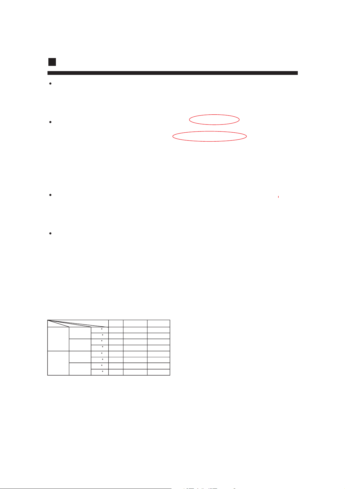
1. Applicable ambient temperature range:
Rated Maximum Minimum
27 32 21
DB C
19.5 23 15
WB C
DB C
35 43 21
WB C
24 26 15
20 27 20
DB C
15 15 15
WB C
7 21 -10
DB C
6 15 --
WB C
Cooling
Heating
Indoor
outdoor
Indoor
outdoor
2. If the supply cord is damaged, it must be
replaced by the manufacturer or its service
agentor a similar qualified person.
3. If the fuse on PC board is broken please
change it with the type of T 3.15A /250VAC.
2
Page 5
Cautions
Safety cautions
Carefully read the following information in order to operate the airconditioner correctly.
Below are listed three kinds of Safety Cautions and Suggestions.
WARNING!
CAUTION!
INSTRUCTIONS: These information can ensure the correct operation of the machine.
Be sure to conform with the following important Safety Cautions.
The Safety Cautions should be at hand so that they can be checked at any time when needed.
If the conditioner is transferred to the new user, this manual should be as well transferred to the new user.
Incorrect operations may result in severe consequences of death or serious injuries.
Incorrect operations may result in injuries or machine damages; in some cases may
cause serious consequences.
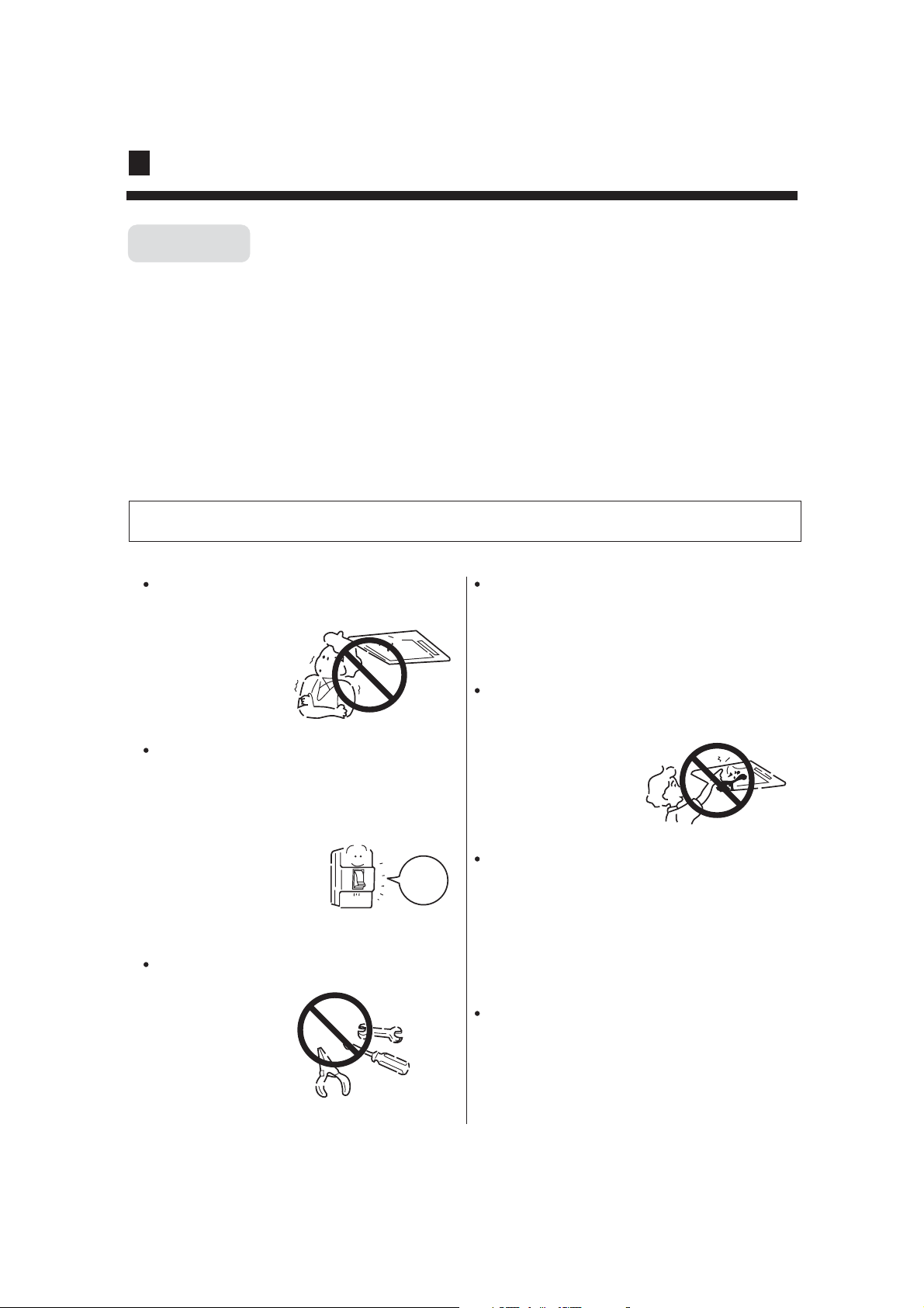
WARNING!
Don't blow the human body with the cooling
air too long, and don't let the room tempera-
ture decrease too low
either.
Otherwise the one
will feel unpleasant
or harm ones' health.
If any abnormal phenomena is found (e. g.
smell of firing), please cut off the power
supply immediately, and contact the dealer
to find out the handling method.
In such case, to continue
using the conditioner will
damage the conditioner,
and may cause electrical
shock or fire hazard.
When need maintenance and repairment,
call dealer to handle it.
Incorrect mainten-
ance and repairment
may cause water
leak, electrical shock
and fire hazard.
switch
off
Please let the dealer be responsible for installing
the conditioner.
Incorrect installation may cause water leak, elec-
trical shock and fire hazard.
Don't put fingers or any other things into the
inlet/outlet and swing louver while the condi-
tioner is in operation.
Because the highspeed
fan is very dangerous
and may cause injuries.
Call the dealer to take measures to prevent the
refrigerant from leaking.
If conditioner is installed in a small room be sure
to take every measure in order to prevent suffoca-
tion accident even in case of refrigerant leakage.
When conditioner is deinstalled or reinstalled
dealer should be responsible for them.
Incorrect installation may cause water leaking,
electrical shock and fire hazard.
3
Page 6
Cautions
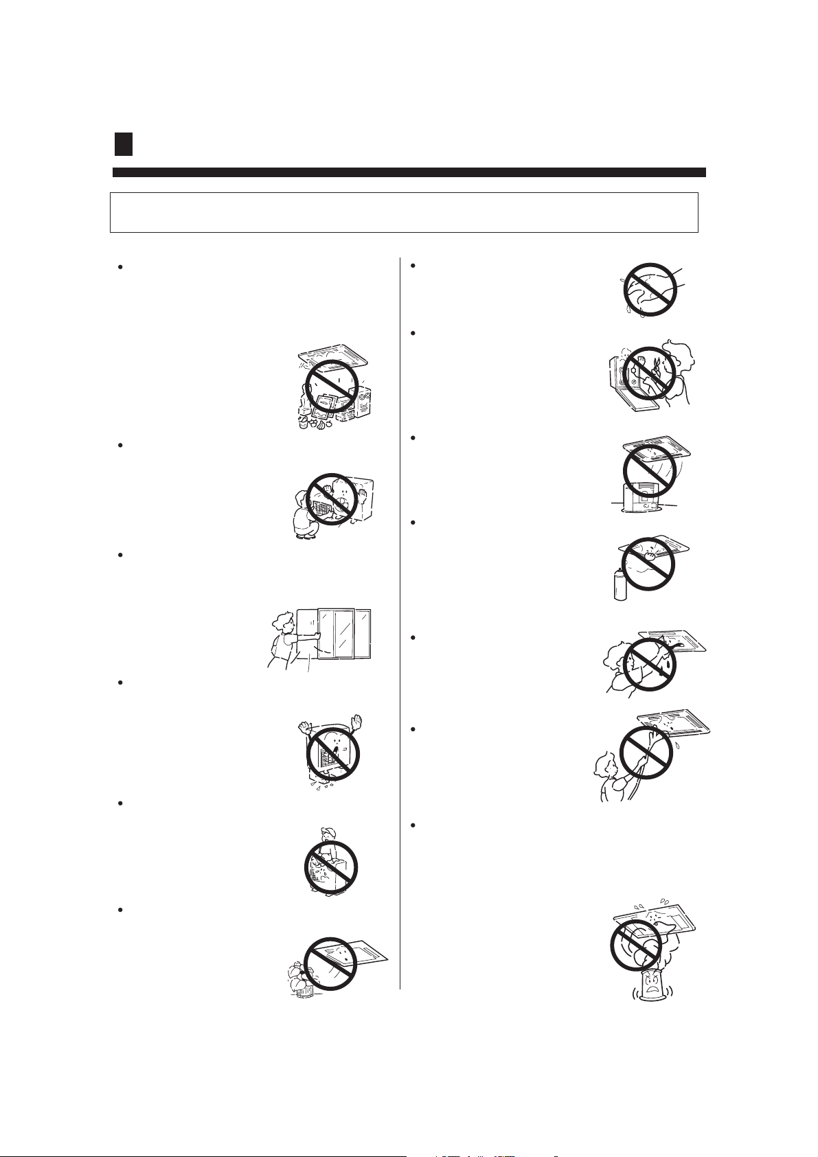
CAUTIONS!
Conditioner should not be used for any other
purpose other than airconditioning.
Don't use air-conditioner for any other special
purposes, e.g. the preservation and protection
of food, animals, plants,
pecision apparatus as well
as work of art, otherwise
the qualities of these
stuffs may be damaged.
Don't dismantle the outlet of the outdoor unit.
The exposure of fan is
very dangerous which
may harm human beings.
When air-conditioner is co-used with other
heat-radiator the frequent replacement of
room atmosphere should be required.
Inefficient ventilation may cause
suffocation.
After a long time use of air-conditioner the
base should be checked for any damages.
If the damaged base is
not repaired, the unit
may fall down and
cause accidents.
No goods or nobody is permitted to placed on
or stand on outdoor unit.
The falling of goods and
people may cause accidents.
Pets and plants should not be blowed directly
in the air flow.
Otherwise will suffer
damage.
Don't operate the air-conditioner with damp hands.
Otherwise will be shocked.
Only use correctly-typed fuse.
May not use wire or any other
materials replacing fuse, otherwise may cause faults or fire
accidents.
Don't place any burning unit
in the air flow of air-conditioner,
which may cause incomplete
combustion.
No inflammable spray fluid
should be permitted to be
placed or used near to airconditioner otherwise may
cause fire accidents.
Air-conditioner should be
cleaned only after power
supply is cut off to keep
from shock or hurt.
Don't clean air-conditioner
with water.
Otherwise may cause
shock.
When use the fumigating insecticide don't
open air-conditioner.
Otherwise the poisonous chemicals may settle
in air-conditioner which harm the health of
chemical-allergic people.
4
Page 7
Cautions
Installation
Please ask the dealer or specialist to install, never try by the users themselves. After the installation please
be sure of the following conditions.
WARNING !
Please call dealer to install the air-conditioner.
Incorrect installation may cause water leaking, shock and fire hazard.
CAUTION !
Air-conditioner can't be installed in the environment with inflammable gases because the
inflammable gases near to air-conditioner may
cause fire hazard.
Installed electrical-leaking circuit breaker.
It easily cause electrical shock without circuit
breaker.
[Location]
Air-conditioner should be located in well-vented
and easily-accessible place.
Air-conditioner should not be located in the
following places:
(a) Places with machine oils or other oil vapours.
(b) Seaside with high salt content in the air.
(c) Near to hot spring with high content of sulfide
gases.
(d) Area with frequent fluctuation of voltage e.g.
factory, etc.
(e) In vehicles or ships.
(f) Kitchen with heavy oil vapour or humidity.
(g) Near to the machine emitting electric-magnetic
waves.
(h) Places with acid, alkali vapuor.
TV, radio, acoustic appliances etc are at least 1 m
far away to the indoor unit, outdoor unit, power
supply wire, connecting wire, pipes, otherwise
images may be disturbed or noises be created.
Connect earthing wire.
Earthing wire should not be connected to the gas pipe, water pipe,
lightning rod or phone line, incorrect earthing may cause shock.
Use discharge pipe correctly to ensure efficient
discharge.
Incorrect pipe use may cause water leaking.
As required, take measures against heavy snow.
Earthing
[Wiring]
Air-conditioner should be equipped with special
power supply wire.
[Operating noise]
Choose the following locations:
(a) Capable of supporting air-conditioner weight,
don't increase operating noise and vibration.
(b) Hot vapour from outdoor unit outlet and ope rating noise don't disturb neighbour.
No obstacles around the outdoor unit outlet.
5
Page 8
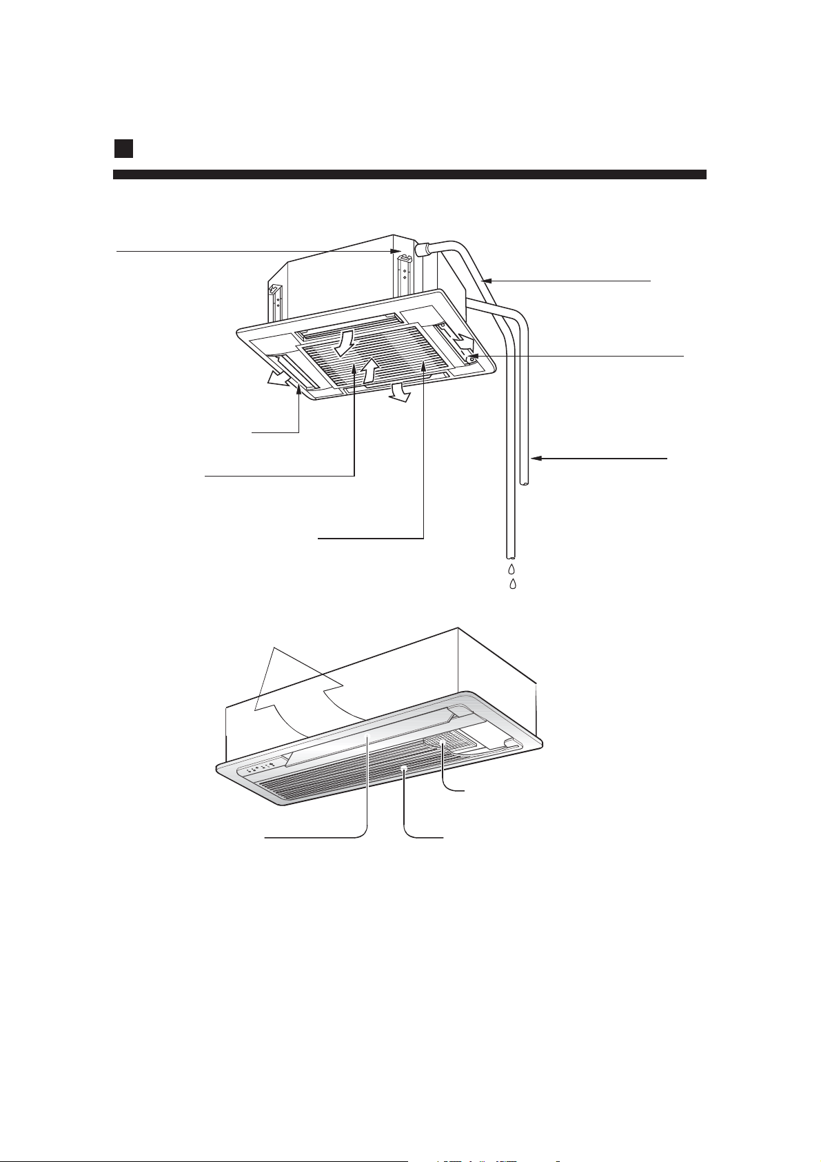
Introduction to Spare Parts
Discharge unit (built in)
In cooling operation,
to discharge the
water from inside the
room.
Drain Hose
Swing fender
(located in the outlet)
Outlet
Air filter
(located in the suction grill)
Suction grill
Refrigerant pipe
Cable line
Earthing line
Anti-bacteria filter
Air intakeAir Outlet
6
Page 9
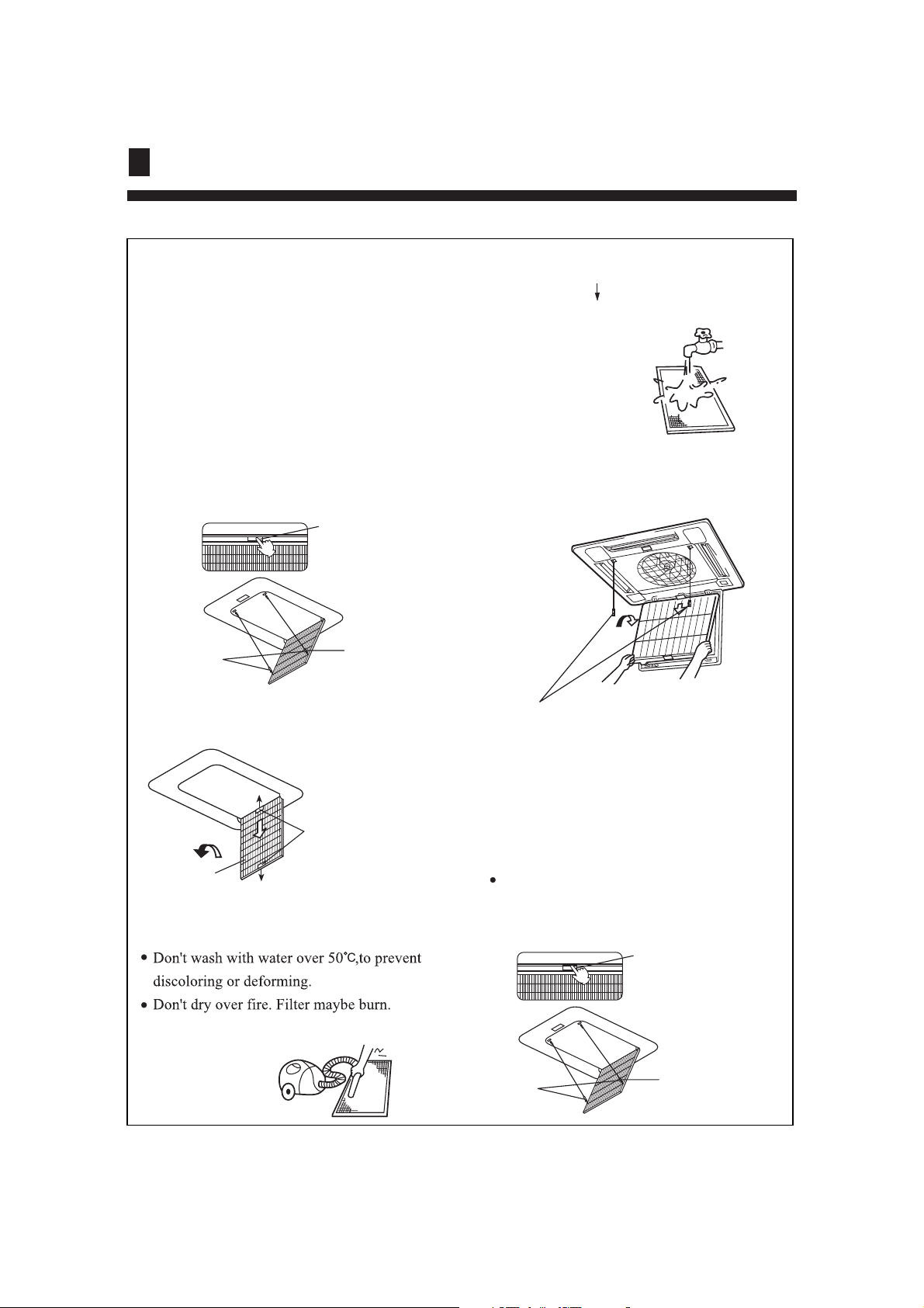
Maintenance
[Clean air filter]
NOTE
1. Open inlet grill
Press the elliptical "PUSH" knob, the inlet
grill will automatically drop. (the inlet grill
is catched with two pothooks)
When having to clean, don't dismantle
air-filter,otherwise may cause faults.
In the environment where there is too
much dust, air filter should be cleaned
for more times.
(about half a year one time)
PUSH
Open two
pothooks
Press the elliptical knob
the inlet grill will
automatically drop
Pothook
(B) Wash with water.
With too much dust, use soft brush and neutral
detergent.
Swing off the water, and then place in cool place.
5. Install air filter
(1) Put filter into protruding parts at the top of
the inlet grill.
(2) Connect the two pothooks with inlet grill
See 2
2. Open two othooks
3. Dismantle air filter
Drag the knob of
the grill back lift
Air filter
the filter and take
down.
4. Clean
CAUTION!
(A) Remove dust with vacuum filter.
Connect the two pothooks with inlet grill
6. Close inlet grill
See 1.
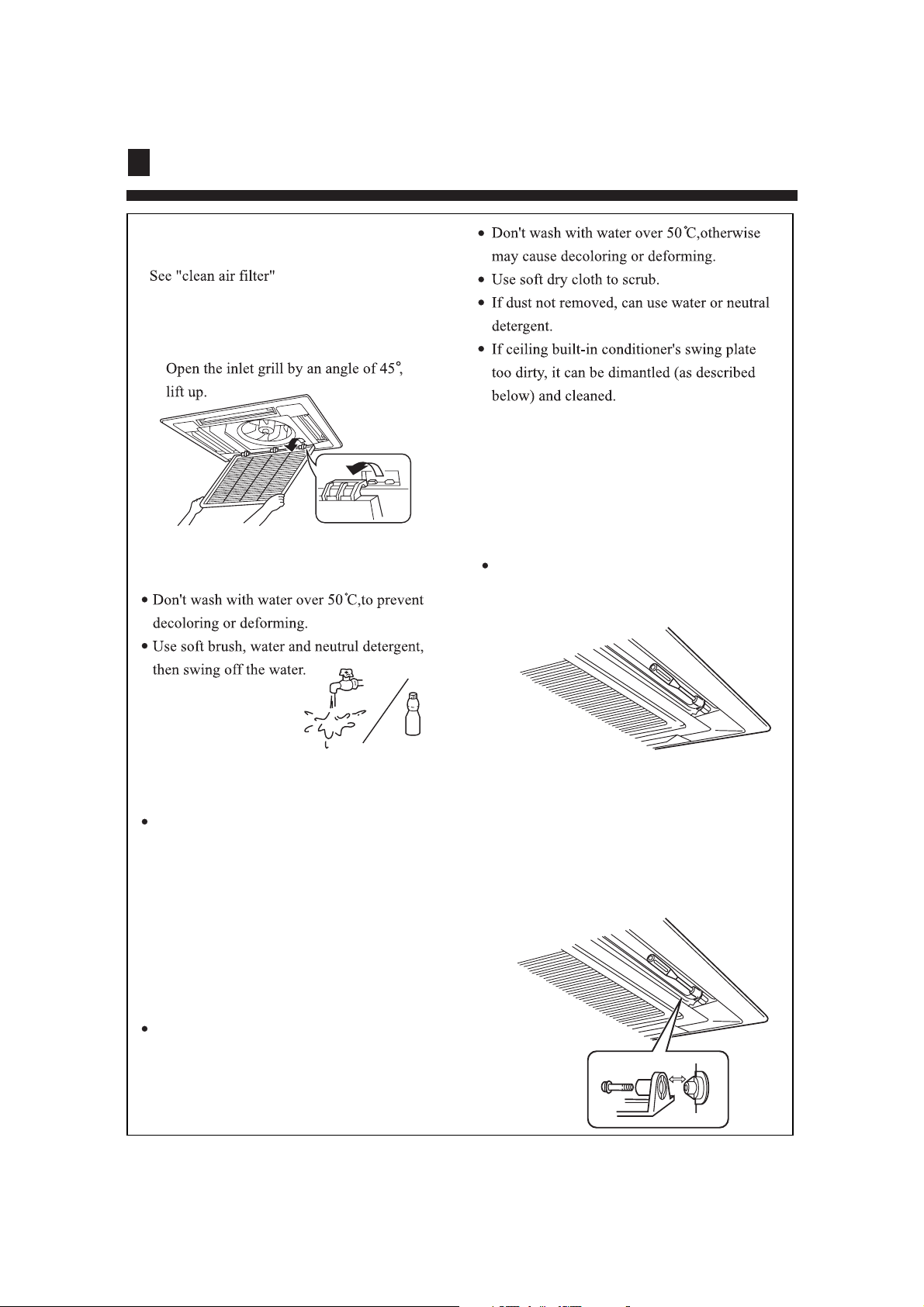
[Clean inlet grill]
1. Open inlet grill
Press the elliptical "PUSH" knob, the inlet
grill will automatically drop. (the inlet grill
is catched with two pothooks)
PUSH
Open two
pothooks
Press the elliptical knob
the inlet grill will
automatically drop
Pothook
7
Page 10
Maintenance
2. Take off airfilter
3. Take of inlet grill
[Dismantle and install swing
plate ]
1. Fix the swing plate at the bottom.
2. Dismantle the swing plate.
4. Clean
CAUTION!
NOTE
When the filter too much dust
To spray the special detergent for vent fan or
utensils.
5. Install inlet grill
6. Install air filter
7. Close inlet grill
see 3
see "Clean air filter"
see 1
[Clean outlet and shell]
CAUTION!
Use water to clean the plate and don't heavily
scrub, otherwise the fine hair may fall off.
Unscrew the screw at both ends of the swing
plate.
[Dismantle and install swing
plate ]
3. Install swing plate
Lightly rotate swing plate to insert the ridge
at both ends of the outlet into the groove
and then screw up.
CAUTION!
Don't use gasoline, benzene, dilutant,
polishing powder, or liquid inseticide.
8
Page 11

Maintenance
Seasonal Reserve
Post-season Care
Operate the unit with FAN mode on a fair day for about half
a day to dry the inside of the unit well.
Stop operation and turn off the power supply switch .Electric
power is consumed even the air conditioner is in stop.
Clean the air filter, indoor unit and outdoor unit,and cover
the unit with dustcoat.
Pre-season Care
See that there is no obstacles blocking the air
inlet and air outlet of both indoor and outdoor
unit to avoid reduce the working efficiency.
Be sure to install the air filter, ensure that the air filter is not dirty. Otherwise may result in
machine damages or cause malfunciton due to dust inside the unit
To prevent compressor when start in HEAT mode,
please cut in the power supply switch 12 hours
before starting run,furthermore, always keep the
power supply switch on during the using senson.
NOTE
The inner part of indoor unit must be cleaned. Consult dealer, because clean must be done by
1.
technician.
In cooling operation, discharging system discharge water in room.
2.
9
Page 12

Trouble Shooting
The followings are not malfuncition
Water flowing sound is heard
Hua
Hua
Cracking sound is heard
It smells.
During operation, white fog comes out of
indoor unit.
When the air conditoner is started, when the
compressor starts or stops during operation
or when the air conditioner is stopped,it sometimes sounds Bi- Bi- or Godo-Godo. It is
the flowing sound of the refrigerant , not a
malfunction.
This is caused by heat expansion or contraction of plastics
Air blown out from the indoor unit sometimes
smells. The smell results from smells of
furniture, paint , tobacco absorbed by indoor
unit.
When in COOL or DRY mode, a thin water
fog can be seen blown out of unit ,this is the
condensed fog because the suddenly cooled
indoor air is blown out.
Automatically switch into FAN mode during
cooling.
The air conditioner cannot be restarted soon
after it stops.
Air conditioner does not start?
To prevent frost from being accumulated on the
indoor unit heat exchanger, it sometimes automatically switched into the FAN mode,but it will
soon back to the cooling mode.
This is because of the self-protection function
of the system, therefore,it cannot be restarted
for about three minutes after it stops.
Please wait for
three minutes
10
Page 13

Trouble Shooting
Air does not blow or the fan speed cannot be
changed during drying.
Water or vapor generated from the outdoor
unit during heating.
During heating,indoor fan is still running even
unit is stopped.
In DRY mode, when room temperature
becomes 2 C higher than temperature setting,
unit rill run intermittently at LO speed regardless
of FAN setting
This happens when the frost accumulated on
the outdoor unit is removed (during defrosting
operation).
Defrosting operation
To get ride of the excess heat, indoor fan will
continue running for a while after unit automatically stops.
Please check the following things about your air conditioner before making a
service call.
Is the power supply switch on ?
**?
Power supply switch is not in
ON position.
Unit fails to start.
Is city supply power normal ?
ON
OFF
11
Is the earth leakage breaker
in action ?
Be sure to turn off the power
supply switch immediately and
contact the sales dealer.
Page 14

When Trouble Happens
Insufficient cooling or heating
The operation controller
adjusted as required
Any obstacle exists at the air
inlet or outlet?
Any other heat sources in the
room?
Air filter too dirty ?
Door or window left opened ?
Insufficient cooling
Sunlight direct into the
room ?
Horizontal swing louver
upward ? (in HEAT mode)
Too crowed in the room ?
Cooled air blown out ( when heating)
When the air conditioner does not operate properly after
you have checked the above-mentioned items or when
following phenomenon is observed,stop the operation of
the air conditioner and contact your sales dealer.
1)The fuse or breaker often shuts down.
2)Water drops off during cooling or drying operation.
3)There is an irregularity in operation or abnormal sound that
is audible.
12
Page 15

When Trouble Happens
1. Error display
Indoor unit malfunction display code
Indoor unit malfunction Display code
Float switch or water motor abnormal E0
Outdoor unit abnormal E1
Liquid temperature sensor is abnormal
Gas temperature sensor is abnormal
Indoor unit adress abnormal
(Firstly you saw E5 in controller LCD,
and then the failure code is changed
from E5 to E9)
Indoor unit EEPROM data is abnormal
E3
E4
E5
E6
The communication with electronic
expansion box is abnormal
The communication between the
wire remote controller and indoor
unit control board is abnormal
The communication between indoor
and outdoor unit is abnormal
Water temp. sensor is abnormal (Only
used for the twin energy source function)
Remote controller Timer and Operation indicator malfunction code
When the unit running, Timer indicator flash stand for indoor unit malfunction
Timer indicator
Flashing times
Flashing once
Flashing twice
Flashing 3 times The environment temperature sensor is abnormal
Flashing 4 times The communication with outdoor unit is abnormal
Flashing 5 times
Flashing 10 times
Flashing 11 times
Flashing 12 times Indoor unit EEPROM data is abnormal
Flashing 15 times Water temp. sensor is abnormal
The liquid tube temperature sensor is abnormal
The gas tube temperature sensor is abnormal
The ommunication with the electronic expansion valve control board is abnormal
Indoor unit PG fan motor is abnormal
Indoor unit water overflow or float switch is abnormal
Indoor unit malfunction
£¤Only used for the twin energy source function£'
Display codeIndoor unit malfunction
E7
E8
E9
E0
Outdoor unit malfunction display code
When the wire remote controller display E1,Can check the outdoor unit control board LED1 or outdoor
unit malfunction display code to sure outdoor unit malfunction.
When the operation indicator flashing stand for outdoor unit malfunction,Operation indicator flashing
times can't determinant outdoor unit malfunction ,You must check the outdoor unit control board LED1
flashing times or outdoor unit malfunction display code to sure outdoor unit malfunction.
Others malfunction manual plese read the outdoor unit manual.
Please keep this manual carefully and safely.
13
Page 16

Customer Need-to-know
Customer Need-to-know
Please install the air conditioner according to the requirements specified in this manual to ensure
the air conditioner work well.
Be careful not to scratch the surface of the case during moving the air conditioner.
Please keep the installation manual for future reference when maintenance and changing installation place.
After installation ,please use the air conditioner according to the specification in the operation
manual.
Using Directions
Adjust suitable airflow direction
Keep the proper indoor temperature.
Too cool or hot is not good for your health.
Furthermore,it will result in excessive
consumption of electric power.
Optimal
temperature
Avoid direct sunlight and airflow
Effectively use timer.
Using TIMER mode, you can make the room
temperature reach a suitable temperature when
you wake up or go back home.
ATTENTION: after finishing installation,confirm no refrigerant leakage.
14
Page 17

Installation Procedure
Installation tools
The installation tools listed in the
following sheet can be used as required.
1. Screw driver
2. Hacksaw
3. Drill with a diameter of 60mm
4. Inner hexagon spanner,shifting
spanner
5. Spanner (14, 17, 19,24,27mm)
6. Pipe cutter
7. Pipe expander
8. Knife
9. Pincers
10. Leakage detector or soapy water
11. Band tape
12. Scraper
13. Refrigerant oil
Standard accessories
The following parts mentioned in this
manual are the installation accessories
we prepared.
Following in the list are the accessories
supplied with the unit,which can be used
as required
No.
1
2
3
4
5
6
7
Accessory parts
Remote controller
Battery
Wire clamp
Heat
insulation
sheathing
Accesories
Screw cap
Remote
controller
bracket
Qty.
1
2
4
1+1
1
1+1
1
Symbol Parts Name
A
B
C
D
E
F
Adhesive tape
Pipe clamp
Connecting hose
Drainage hose
Non-hydroscopic
heat insulating material
Gypsum powder
15
Page 18

Installation Procedure
CAUTIONS:
To ensure proper installation, read "Cautions" carefully before
installation, start the unit correctly and show
customers how to operate and
working. After
maintain the unit.
Meanings of Warning and Cautions:
Warning! Serious injury or even death might happen, if it is not observed.
Caution! Injury to people of damages to machine might happen, if it is not observed.
WARNING!
Installation shall be done by professional people, don't install unit by yourself. Incorrect installation will
cause water leakage, electric shock or fire.
Install unit as per the Manual. Incorrect installation will cause water leakage, electric shock or fire
accident.
Be sure to use specified accessaries and parts. Otherwise, water leakage, electric shock, fire accident or
unit falling down may happen.
Unit should be placed on a place strong enough to hold the unit. Or, unit will fall down causing injuries.
When install the unit, take in consideration of storms, typhoom, earthquake. Incorrect installation may
cause unit to fall down.
All electric work shall be done by experienced people as per eocal code, regulations and this Manual.
Use exclusive wire for the unit. Incorrect installation or undersized electric wire may cause electric
shock or fire accident.
All the wires and circuit shall be safe. Use exclusive wire firmly fixed. Be sure that external force
will not affect terminal bolck and electric wire. Poor contact and installation may cause fire accident.
Arrange wire correctly when connectin indoor and outdoor power supply. Fix terminal cover firmly to
avoid overheat, electric shock or even fire accident.
In case retrigerant leakage occurred during unit installation, keep a good ventilation in the room.
Poisonous gas will occur when meet with fire.
Check the unit upon installation. Be sure there is no leakage. Refrigerant will induce poisonous gas
when meet heat source as heater, oven, etc.
Cut power supply before touching terminal bolck.
CAUTION!
Unit shall be grounded. But grounding shall not be connected to gas pipe
water pipe, telephone line. Poor grounding will cause electric shock.
Be sure to install a leakage breaker to avoid electric shock.
Arrange water drainage according to this Manual. Cover pipe with insulation materials in case
dew may occur. Unproper installation of water drainage will cause water leakage and wet your furniture.
To maintain good picture or reduce noise, keep at least 1 m from T.V. radio, when install indoor and outdoor unit, connecting wire and power cable. (If the radio wave is relatively strong, 1 m is not enough
to reduce noise).
Don't install unit in following places:
(a) Oil mist or oil gas exists, such as kitchen, or, plastic parts may get aged, or water leakage.
(b) Where there is corrosive gas. Copper tube and welded part may be damaged due to corrosion,
causing leakage.
(c) Where there is strong radiation. This will affect unit's control system, causing malfunction of the unit
(d) Where flamable gas, dirt, and volatile matter (thinner, gasoline) exist, These matter
might cause fire accident.
Refer to paper pattern when installing unit.
Cautions for the installation personnel
Don't fail to show customers how to operate unit.
16
Earthing
Page 19

Installation Procedure
1
1. BEFORE INSTALLATION
Determine the way to carry unit to installation place.
Don't remove packing until unit reaches installation place.
If unpacking is unavoidable, protect unit properly.
2
2. SELECTION OF INSTALLATION PLACE
(1) Installation place shall meet the following and agreed by customers:
Place where proper air flow can be ensured.
No block to air flow.
Water drainage is smooth.
Place strong enough to support unit .
Place where inclination is not evident on ceiling.
Enough space for maintenance.
Indoor and outdoor unit piping length is within limit. (Refer to Installation Manual for outdoor unit.)
Indoor and outdoor unit, power cable, inter unit cable are at least 1 m away fromT.V. radio. This is helpful
to avoid picture disturbance and noise. (Even if 1 m is kept, noise can still appear if radio wave is strong)
(2) Ceiling height
Indoor unit can be installed on ceiling of 2.5-3m in height. (Refer to Field setting and Installation Manual of
ornament panel.)
(3) Install suspending bolt. Check if the installation place is strong enough to hold weight. Take necessary
measures in case it is not safe. (Distance between holes are marked on paper pattern. Refer to paper pattern
for place which need be reinforced)
<Don't discard any accessories until completed>
Air outlet
1500 Over
AB424FCAHA
Air outlet
Air inlet
2500 Over
AB484FCAHA
Installation space
310
1500 Over
Air outlet
1500 Over
AB184FCAHA
Air outlet
Air inlet
2500 Over
AB244FCAHA
260
1500 Over
AB094FAAHA AB124FAAHA
17
Page 20

Installation Procedure
3
3. PREPARATION FOR THE INSTALLATION
(1) Position of ceiling opening between unit and suspending bolt.
AB424FCAHA AB484FCAHA
860-890
780
(Ceiling opening)
(Distance between suspending bolts)
AB184FCAHA AB244FCAHA
Refrigerant pipe
680
840(Indoor unit)
950(Ornament panel)
£¤Ceiling opening)
(Distance between suspending bolts)
620
860-890
890(Ceiling opening)
*
(Distance between suspending bolts)
680
(Distance between suspending bolts)
840(Indoor unit)
890(Ceiling opening)
*
950(Ornament panel)
AB094FAAHA AB124FAAHA
807.6
761
700
A
Suspending bracket
Ceiling
A
460
500(GRILLE)
712.6
831
860(GRILLE)
350
438
Note:
Dimension of ceiling opening marked with * can be as
large as 910mm, but the matching part of ceiling with
ornament panel shall be over 20mm.
20 Over
(2) Cut an opening in ceiling for installation if necessary. (when ceiling already exists.)
Refer to paper pattern for dimension of ceiling hole.
Connect all pipings (refrigerant, water drainage), wirings (inter unit cable) to indoor unit, before installation.
Cut a hole in ceiling, may be a frame should be used to ensure a smooth surface and to prevent vibration.
Contact your real estate dealer
(3) Install a suspending bolt.
(Use a M10 bolt)
To support the unit weight, anchor bolt shall be used in the case of already exists ceiling. For new
ceiling, use built-in type bolt or parts prepared in the field.
Before going on installing adjust space between ceiling.
Suspending bolts
(160)
<Installation example>
Anchor bolt
Long nut
50~100
Suspending bolt
Ceiling
Roof
Note: All the above mentioned parts shall be prepared in field.
18
Page 21

Installation Procedure
4
4. INSTALLATION OF INDOOR UNIT
In the case of new ceiling
(1) Install unit temporarily
Put suspending bracket on the suspending bolt. Be sure to use nut and washer at both ends of the bracket.
(2) As for the dimensions of ceiling hole, see paper pattern. Ask your real estate dealer for details.
Center of the hole is marked on the paper pattern.
Center of the unit is marked on the card in the unit and on the paper pattern.
Mount paper pattern onto unit using 3 screws . Fix the corner of the drain pan at piping outlet.
< After installation on the ceiling >
(3) Adjust unit to its right position. (Refer to preparation for the installation-(1))
(4) Check unit's horizontal level.
Water pump and flating switch is installed inside indoor unit, check four corners of the unit for its level
using horizontal compartor or PVC tube with water. (If unit is tilting against the direction of water drainage,
problem may occur on floating switch, causing water leakage.)
(5) Remove the washer mounting , and tighten the nut above.
(6) Remove the paper pattern.
In the case of ceiling already exists
(1) Install unit temporarily
Put suspending bracket on the suspending bolt.
Be sure to use nut and washer at both ends
of the bracket. Fix the bracket firmly.
(2) Adjust the height and position of the unit.
(Refer to preparation for the installation (1) ).
(3) Proceed with and of "In the case of new ceiling".
5
2
4
3
6
Nut (Prepare in feild)
Washer (Prepared in feild)
Suspending bolts
Fasten (double nuts)
Level
Polythene pipe
Center of ceiling hole Paper pattern
Screw (accessory)
[Fix the paper pattern]
19
Insert
Washer fixing pad
(prepared in feild)
[ secure the washer firmly]
Screws at the piping outlet is fixed at the corner
of drain pan.
Paper pattern
5
Screw (accessory)
Page 22

Installation Procedure
5. REFRIGERANT PIPING
5
(As for outdoor piping, please refer to installation Manual of outdoor unit.)
Outdoor is precharged with refrigerant.
Be sure to see the Fig.1, when connecting and removing piping from unit.
For the size of the flare nut, please refer to Table 1.
Apply refrigerant oil at both inside and outside of lflare nut. Tighten it band tight 3-4 turns then tighten it.
Use torque specified in Table 1. (Too much force may damage flare nut, causing gas leakage).
Check piping joints for gas leakage. Insulate piping as shown in Fig. below.
Cover joint of gas piping and insulator with seal.
Apply refrigerant oil
Torque spanner
Piping joing
Flare nut
6
6. INSTALLATION OF WATER DRAINAGE PIPE
Medium size seal pad 11 (accessory)
(Cover the piping joint
with seal pad.)
Clamp 3
spanner
Gas pipe
Liquid pipe
7
Insulator (accessory)
(For liquid pipe)
Insulator (accessory)
(For gas pipe)
8
7
Table 1
Pipe
size
6.35
9.52
15.88
19.05
Tighten
torque
1420~1720N.cm
(144~176kgf.cm)
3270~3990N.cm
(333~407kgf.cm)
6180~7540N.cm
(630~770kgf.cm)
9720~11860N.cm
(990~1210kgf.cm)
A(mm)
8.3~8.7
12.0~12.4
18.6~19.0
22.9~23.3
Flare shape
2
45
0.5
90
(1) Install water drainage pipe
Pipe dia, shall be equal or larger than that of unit piping.(pipe of polyethene; size: 25mm; O.D:32mm)
Drain pipe should be short, with a downward slope at least 1/100 to prevent air bag from happening.
If downward slope can't be made, take other measures to lift it up.
Keep a distance of 1-1.5m between suspending brackets, to make water hose straight.
1-1.5m
R0.4 ~ 0.8
A
Slope over 1/100
Use the self-provided stiff pipe and clamp with unit. Insert water pipe into water plug until it reaches the
1
white tape. Tighten the clip until head of the screw is less than 4mm from hose.
Wind the drain hose to the clip using seal pad 9 .
Insulate drain hose in the room.
Clamp
Tape (White)
Self-provided stiff pipe
<Cautions for the drain water lifting pipe>
Clamp
(accessory)
Large size seal pad
(accessory)
4mm below
10
Installation height shall be less than 280mm.
There should be a right angle with unit, 300mm from unit.
Suspending bracket
1~1.5m
drain water lifting pipe
Clamp
(accessory)
280 below
220
500 below
Self-provided stiff pipe
(accessory)
75 below
500 below
(Note)
Drain hose
(accessory)
300mm below
The slope of water drain hose (1) shall be within 75mm, don't apply too much force on it.
If several water hoses join together, do as per following proceedures.
Connect water hoses with a T joint.
Over 100
Specifications of the water hoses shall meet the requirements for the unit running.
20
Page 23

Installation Procedures
7.
INSTALLING THE DECORATED BOARD ON THE BODY OF INDOOR UNIT
7
As shown in Fig. 1, make the wind deflector motor of the decorated board face to the orifice of the indoor
6
unit, and then mount the decorated board onto the body of the indoor unit.
swing ring
orifice location
2
deflector motor
3
1
2
4
Mounting the decorated board:
a. Hang temporarily the swing rings(2 pcs) opposite to the deflector motor of the decorated board on the ring
stators of the swing rings of the indoor unit;
b. Hang temporarily the other swing rings on the ring stators of the swing rings of the indoor unit (take care
not to get the lead wire of the deflector motor into the sealing);
c. Screw all 4 hex head screws under the rings about 15mm to lift the board;
d. Turn and adjust the decorated board in the direction of arrow as shown in Fig. 4 until it covers the hole of
the ceiling.
e. Fasten the screw to keep the thickness of the sealing between the decorated board and the unit body within
5-8mm, as shown in Fig. 2.
indoor unit
ceiling material
f. Mount the wiring of the decorated board according to the mounting drawing attached tothe inside of the
machine;
g. Check with the control if the mounting is correct and make sure if the machine work snormally;
h. Mount the air inlet grid and angle covers.
sealing
5-8mm
decorated board
Fig.1
Fig.2
21
Page 24

Installation Procedures
Attention
Inappropriate tightening of screws might cause the faults as
shown in Fig. 3.
Tighten the screws properly.
If there is still a gap between the decorated board and the ceiling
after tightening the screws, please readjust the height of the body
of the indoor unit. (Fig. 4)
If the indoor unit keeps the horizontal level and the drainpipe
cant be influenced, adjust the height of the body of the indoor
unit from the holes on the angles of the decorated board.
air leakage
leakage
from roof
pollution
Fig.3
vapour condensate drops
any gap is not allowed
Wiring of Decorated Board
a. Connect it to the connector of the wind deflector motor lead on the decorated board (Fig. 5);
b. Connect it to the receiving terminal of remote control on the decorated board.
side of decorated board
electrical cabinet
AB184~484FCAHA
<circuit diagram>
side of indoor unit
(different from the actual condition)
Fig.4
Fig.5
22
Page 25

Installation Procedures
Mounting Air Inlet Grid and Angle Covers
(1) Mounting the air inlet grid:
Take care not to wind the lead of the wind deflector motor during mounting the air inlet grid.
(2)For Model AB184-484FCAHA units, the angle covers should be mounted on the angles.
¢ Tie the thread of the angle cover onto the cleat on the decorated board as shown in Fig. 6.
¢ Mount the angle cover onto the decorated board (as shown in Fig. 7).
cleat
Slide the 5 locks to mount angle covers
to fit the holes on decorated board
Fig.6 Fig.7
Attention
£¡
For proper drainage, the drainpipes should be connected according to the installation manual. Heat
preservation should be performed as to prevent condensing. Improper connections may cause the water
leakage.
Requirements:
The drainpipe of the indoor unit should be heat-insulated.
Heat insulation should be treated for the connection with the indoor unit. Improper heat insulation may cause
condensing.
The drainpipe with the down gradient of over 1/100 cant be in the S shape, or abnormal sound can be caused.
The lateral length of the drainpipe should be kept with 20m. Under the condition of long pipes, supports can
be provided every 1.52m as to avoid unevenness.
The central piping should be connected according the following drawing.
Take care not to apply external force on the connection of the drainpipes.
heat
insulating
material
1.5m~2m
down gradient
over 1/100
support bracket
s-shape elbow
as big as possible (about 10 CM)
down gradient
over 1/100
VP30
23
Page 26

Installation Procedures
Piping Materials & Heat Insulating Materials
As to prevent condensation, heat insulating
treatment should be performed. The heat
insulating treatment for piping should be done
respectively.
Piping
Material
Heat Insulating
Material
Hard PVC tube VP31.5mm
(inner bore)
Vesicant polythene
thickness: over 7mm
Hose
The attached hoses can be used to adjust the eccentricity and angle of the hard PVC tube.
Stretch the hose directly to make connections as to avoid distortion. The soft end of the hose should be
positioned with a clamp.
The hose should be used in the lateral direction.
eccentricity adjustment (max.20mm)
o
45 bending (max.)
20
hose
o
45
indoor unit
hose clamp
hose
Heat Insulating Treatment:
Wrap the connection between the clamp and the root segment of the indoor unit without any gap with heat
insulating materials as shown in the drawing
hose hose clamp
Lifting Drainpipe
The drainpipe can be lifted 360mm.
When the down gradient of the drainpipe cant be ensured, after upright
lifting, the drainpipe is in the down slope.
attached heat
insulating material
heat insulating
material
horniness pvc pipe
Confirming Drainage
The drainage should be confirmed during the test run to make sure that there is
leakage at the connection.
The confirmation of drainage should be also performed during the installation in
the winter season.
Fill water from the outlet or the specified position and confirm the drainage.
Fill 600cc water with a hose from the outlet or the specified location on the machine.
Add the water slowly. Dont add water to the motor of the drainage pump.
After mounting the electrical system, do refrigerating operation and meanwhile
add water and check.
If the electrical installation hasnt been completed, pull out the terminal(2P)
of the floater switch on the electrical cabinet. After confirming the drainage,
connect the terminal of the floater switch and run the drainage pump for 5
minutes until it stops automatically.
Confirm the sound of the motor:
Confirm the sound of the motor of the drainage pump and meanwhile check
the drainage.
24
lifting
360mm below
100mm
below
indoor unit
under the ceiling
lifting 500mm below
joint of drainpipe
Page 27

Installation Procedure
Tubing Permissible Length & Height Difference
Please refer to the attached manual of outdoor units.
Tubing Materials & Specifications
Model
Tubing Size
(mm)
Tubing
Material
AB094~
124FAAHA
Gas pipe
Liquid pipe
Phosphor deoxybronze seamless pipe (TP2) for
air conditioner
12.70
6.35
AB184~
244FCAHA
15.88
9.52
AB424~
484FCAHA
19.05
9.52
Refrigerant Filling Amount
Add the refrigerant according to the installation instruction of outdoor unit. The addition of R22
refrigerant must be performed with a measure gage to ensure the specified amount while compressor
failure can be caused by filling too much or little refrigerant.
Connecting Procedures of Refrigerant Tubing
Proceed the flare tube connecting operation to connect all the refrigerant tubes.
Dual wrenches must be used in the connection
of indoor unit tubing.
Mounting torque refers to the right table
wrench
Outer
Diameter of
Tubing (mm)
6.35
9.52
12.70
15.88
19.05
Mounting
Torque (N-m)
11.8(1.2kgf-m)
24.5(2.5kgf-m)
49.0(5.0kgf-m)
78.4(8.0kgf-m)
98.0(10.0kgf-m)
13.7(1.4kgf-m)
29.4(3.0kgf-m)
53.9(5.5kgf-m)
98.0(10.0kgf-m)
117.7(12.0kgf-m)
Increase mounting
Torque (N-m)
Cutting and Enlarging
Cutting or enlarging pipes should be proceeded
by installation personnel according to the
operating criterion if the tube is too long or flare
opening is broken.
Vacuumizing
Vacuumize from the stop valve of outdoor units
with vacuum pump. Refrigerant sealed in indoor
machine is not allowed to use for vacuumization.
Open All Valves
Open all the valves of outdoor units. [NB: oil
balancing stop valve must be shut up completely
when connected one main unit.]
Checkup for Air Leakage
Check if there is any leakage at the connecting part
and bonnet with hydrophone or soapsuds.
Connecting
Connecting
circular terminals:
1. Connecting circular terminals:
The connecting method of circular terminal is
shown in the Fig. Take off the screw, connect it
to the terminal tier after heading it through the
ring at the end of the lead and then tighten it.
2.Connecting straight terminals:
The connection methods for the circular terminals
are shown as follows: loosen the screw before
putting the line terminal into the terminal tier,
tighten the screw and confirm it has been clamped
by pulling the line gently.
3.Pressing connecting line
After connecting line is completed, press the
connecting line with clips which should press on
the protective sleeve of the connecting line.
correct
pressing
terminal tier
pressing clip
25
wrong
pressing
Page 28

Electrical Wiring
Warning
Electrical construction should be made with specific mains circuit by the qualified personnel according
to the installation instruction. Electric shock and fire may be caused if the capacity of power supply
is not sufficient.
During arranging the wiring layout, specified cables should be used as the mains line, which accords
with the local regulations on wiring. Connecting and fastening should be performed reliably to avoid
the external force of cables from transmitting to the terminals. Improper connection or fastness may
lead to burning or fire accidents.
There must be the ground connection according to the criterion. Unreliable grounding may cause
electrical shocks. Do not connect the grounding line to the gas pipe, water pipe, lightening rod and
telephone line.
Attention
Only copper wire can be used. Breaker for electric leakage should be provided, or electric shock may
occur.
The wiring of the mains line is of Y type. The power plug L should be connected to the live wire and
plug N connected to null wire while should be connected to the ground wire. For the type with auxiliary
electrically heating function, the live wire and the null wire should not be misconnected, or the surface
of electrical heating body will be electrified. If the power line is damaged, replace it by the professional
personnel of the manufacturer or service center.
The power line of indoor units should be arranged according to the installation instruction of indoor units.
The electrical wiring should be out of contact with the high-temperature sections of tubing as to avoid
melting the insulating layer of cables, which may cause accidents.
After connected to the terminal tier, the tubing should be curved into be a U-type elbow and fastened
with the pressing clip.
Controller wiring and refrigerant tubing can be arranged and fixed together.
The machine cant be powered on before electrical operation. Maintenance should be done while the
power is shut down.
Seal the thread hole with heat insulating materials to avoid condensation.
Signal line and power line are separately independent, which cant share one line. [Note: the power line,
connecting line, signal line are provided by users. Parameters are shown as below: 3×(1.0-1.5) mm
parameters for signal line: 2×(0.75-1.25)mm
2
( shielded line)]
2
;
Supply Wiring Drawing
communication
C2
C1
C2
C1
R
R
communication
Note:
1:L(black)
2:N(white)
3:C(red)----It's no use for Builtin EEV Type on the indoor unit .
OUTDOOR UNIT TERMINAL BLOCK
U
W
V
CM
Compressor
INDOOR UNIT TERMINAL BLOCK
1 2 3
W B R
POWER SUPPLY:1PH,220-230V,50/60Hz
R
POWER SUPPLY:
Y/G
ST
26
AU52LFIAHA
N
Lm1
3N~,380-400V,50 /60Hz
AB094FAAHA
AB124FAAHA
AB184FAAHA
AB244FAAHA
AB424FAAHA
AB484FAAHA
Lm2
Page 29

Electrical Wiring
Field setting
Field setting the unit number
Indoor unit number setting
Indoor unit number setting switch and confirmation of the settings.
There is a 4-position dial switch for setting the indoor unit number and fan speed level on the computer board of the indoor unit.
Setting way is as follows:
Before connecting the power supply, please set the indoor unit number manually according to the following table
Matrix of the dial switch and indoor unit number
Position 1 Position 2 Position 3 Representing unit number
000 1
100 2
010 3
110 4
001 5
101 6
011
111
1
The first bit of SW02 and SW03 is used to choose
wired control or remote control type .
ONmeans that the unit with wired controller .And
OFFis remote controller.
2
The second bit of SW02 is used to choose built-in or
outside electronic expansion valve setting.
ON means built-in type.And "OFF"means outside type.
3
The second bit of SW03 is used to select the twin energy
source function.
"ON":The unit without TES function.
"OFF":The unit can be used as TES function.
When it is used for TES function ,the water tempeture
sensor is available .
7
8
SW02
Example:
SW03
Example:
ON
Pos.1
ON
Pos.1
Pos.
SW01
Example:
ON
: 0
010
ON
Pos.2Pos.3Pos.
Pos.1
Setting for No. 3 indoor unit
2
ON
"ON" means that in heating mode the
indoor unit fan speed can be choosed to
middle and low level. "OFF" means that
the indoor unit fan speed can be choosed
to high, middle and low level.After
Pos.
2
producing in plant , the position is "OFF".
OFF
: 1
1
4
Auto restart (
After the Auto restart is set, if power failure suddenly occurs while the air conditioner is working, it will resume the
previous working state when the power is supplied again.
*The setting method of auto restart function of wired remote control model or wired control+ remote control model:press
the [sleep] button of the wired control or remote control 10 times within 5 seconds and after the buzzer rings 4 times,the
air conditioner will enter the state of auto restart function.
The cancel method :press the [sleep] button of the wired control or remote control 10 times within 5 seconds and after the
buzzer rings 2 times, the Auto restart function will be cancelled.The setting method of wireless remote control:press the
[swing] button of the remote control 10 times within 5 seconds and after the buzzer rings 4 times,the air conditioner
will enter the state of auto restart function;
The cancel method :press the [swing] button of wireless remote controller 10 times within 5 seconds and after the buzzer
rings 2 times, the Auto restart function will be cancelled;
*The setting method of wireless remote control:press the [swing] button of the remote control 10 times within 5 seconds
and after the buzzer rings 4 times,the air conditioner will enter the state of auto restart function;
The cancel method :press the [swing] button of wireless remote controller 10 times within 5 seconds and after the buzzer
rings 2 times, the Auto restart function will be cancelled;
Notes: When a power failure suddenly occurs during the air conditioner is working after the Auto restart is set, if the air
conditioner will not be used for a long time, please cut off the power supply to prevent its operation from being resumed
after the power is supplied again, or press the "Switch On/Off" button after the power comes again.
to be applied for a necessary situation
)
:
27
Page 30

Electrical Wiring
The unit has temperature compensation function.
(
Only used for remote controller)
You can use [swing] button of the remote controller to set or cancel temperature compensation function.
(1) About temperature compensation function setting
* The setting method for heating mode:
press [ON/OFF] button of the remote controller to start the indoor unit, setting temperature: 24¡ , press [swing] button 7
times in 5 seconds, the buzzer will ring twice, and enter heating temp. compensation mode.
set compensation temp. , if the set temp.is 25¡ , the compensation temp. is +1¡ , you can set it in range of 0¡ to +6¡
*The setting method for cooling mode:
press [ON/OFF] button of the remote controller to start the indoor unit, setting temperature:24¡ : press [swing] button
7 times in 5 seconds, the buzzer will ring twice, and enter cooling temp. compensation mode.
(2) Temperature compensation function checking
*In cooling mode, setting temp.: 30 degree, High fan speed, press [swing] button 7 times in 5 seconds, The Running lamp
will flash, the times of flash is same with cooling compensation setting number
*In heating mode, setting temp. :16 degree, high fan speed, press [swing] 7 times in 5 seconds, the running lamp will flash,
the flashing times is same with heating compensation setting number
Concerning MRV Auto Restart function for H-MRV models
Haier Auto Restart function when the unit power drops down suddenly, the unit microprocessor will store the previous
working condition and when the power is on again, the unit will run as this memory.
Auto Restart function is designed basically on the MRV whole system, but it is suitable for each indoor unit individually.
If some of indoor units power cut down, but the outdoor unit and the other indoor units still work, maybe problems will
happen such as freezing at cooling mode and overload protection at heating mode on those indoor units without power.
Reason
When one or some indoor units power drops down and the other indoor units are still work, the indoor units without
the power, will keep the previous working condition before the power is off.
And expansion valve keeps open at a kind of opening rate condition as the previous requirement,so there is refrigerant
flowing in the exchanger, but the indoor fan stops working. If the units work at cooling mode, the indoor units without the
power will maybe make freezing. If the unit works at heating mode, maybe the outdoor unit compressor will stop because
of the pressure or temperature protection. This is our design basically on Auto Restart function currently.
Haier, Herewith, solemnly informs our customers, installers, distributors, etc. when making installation,
please make sure when the power is shut down whether artificially or accidentally, the whole system
including outdoor unit and all the indoor units must be off. If you do not make the installation as
our indication, Haier will not be responsible for any problem resulting from this.
Pay special care to the following and check after installation
Item to the checked
Is gas leakage check performed?
Is unit properly insulated?
Is water drainage smooth?
Is power voltage meet that stipulated on the nameplate?
Is wiring and piping correctly arranged?
Is unit safely grounded?
Is wire size correct?
Are there any obstacles on air inlet and outlet grill of
indoor and outdoor unit?
Is record made for piping length and refrigerant
charging amount?
Unproper installation may cause
Unit might fall down, make vibration or noise.
This may lead to gas shortage.
Dew or water drop may occur.
Dew or water drop may occur.
Problem may occur or parts got burned.
Problem may occur or parts got burned.
There might be a danger of electric shock.
Problem may occur or parts got burned.
This may cause poor cooling.
It is hard to control refrigerant charging
amount.
28
Check
Page 31

Technical Specifications
Model
Power Supply
Cooling Capacity
heating Capacity
Noise
(Indoor Units)
Net Weight
(Indoor Units)
Air Volume
(Indoor Units)
Net Dimensions(mm)
Panel Dimensions(mm)
Refrigerant liquid pipe/
Refregerant gas pipe
Model
Power Supply
Cooling Capacity
heating Capacity
Noise
(Indoor Units)
Net Weight
(Indoor Units)
Air Volume
(Indoor Units)
AB094FAAHA
1PH.220V~,60Hz
AB424FCAHA
1PH.220V~,60Hz
2800W
3200W
--
20kg
3
400m
/h
710*440*270
860*500*60
6.35/12.7
2800W
3200W
35kg
3
1580m
/h
AB124FAAHA
1PH.220V~,60Hz
3600W
3900W
--
20kg
450m3/h
710*440*270
860*500*60
6.35/12.7
AB484FCAHA
1PH.220V~,60Hz
3600W
3900W
42dB(A)37dB(A)
35kg
1920m3/h
A184FCAHA
1PH.220V~,60Hz
6000W
6300W
34dB(A)
28kg
3
900m
/h
840*840*240
950*950*80
9.52/15.88 9.52/15.88
AB244FCAHA
1PH.220V~,60Hz
7200W
8000W
35 dB(A)
28kg
1020m
840*840*240
950*950*80
3
/h
Net Dimensions(mm)
Panel Dimensions(mm)
Refrigerant liquid pipe/
Refregerant gas pipe
950*950*80
9.52/19.05 9.52/19.05
950*950*80
29
 Loading...