

Page 1

SERVICE MANUAL
LED TV
MODEL No. 32E2000
WARNING
This service information is designed for experienced repair technicians only and is not designed for use by the general public.
It does not contain warnings or cautions to advise non-technical individuals of potential dangers in attempting to service a product.
Products powered by electricity should be serviced or repaired only by experienced professional technicians. Any attempt to service
or repair the product or products dealt with in this service information by anyone else could result in serious injury or death.
Page 2

Service Manual
Model No.: 32E2000
Table of Contents
1. General Information . . . . . . . . . . . . . . . . . . . . . . . . . . . . . . . . . .3
1-1. General Guidelines . . . . . . . . . . . . . . . . . . . . . . . . . . .3
1-2. Important Notice . . . . . . . . . . . . . . . . . . . . . . . . . . . . .3
1-3. How to Read this Service Manual . . . . . . . . . . . . . . . .6
2. Specifications . . . . . . . . . . . . . . . . . . . . . . . . . . . . . . . . . . . . . .7
3. Location of Controls and Components . . . . . . . . . . . . . . . . . .8
3-1 Component Location . . . . . . . . . . . . . . . . . . . . . . . . . . .8
3-2 Main Board . . . . . . . . . . . . . . . . . . . . . . . . . . . . . . . . . .8
3-3 LED Panel . . . . . . . . . . . . . . . . . . . . . . . . . . . . . . . . . .11
4. Disassembly Procedures . . . . . . . . . . . . . . . . . . . . . . . . . . . .12
5. Accessories . . . . . . . . . . . . . . . . . . . . . . . . . . . . . . . . . . . . . . .17
6. Installation Instructions . . . . . . . . . . . . . . . . . . . . . . . . . . . . .18
6-1 Power Connection . . . . . . . . . . . . . . . . . . . . . . . . . . .18
6-2 External Equipment Connections . . . . . . . . . . . . . . . .19
7. Operation Instructions . . . . . . . . . . . . . . . . . . . . . . . . . . . . . .25
7-1 Side Control . . . . . . . . . . . . . . . . . . . . . . . . . . . . . . . .25
7-2 Rear Terminals . . . . . . . . . . . . . . . . . . . . . . . . . . . . . .26
7-3 Using Remote Control . . . . . . . . . . . . . . . . . . . . . . . .27
8. Electrical Parts . . . . . . . . . . . . . . . . . . . . . . . . . . . . . . . . . . . . .28
8-1 System Block Diagram . . . . . . . . . . . . . . . . . . . . . . . .28
8-2 Circuit Diagram . . . . . . . . . . . . . . . . . . . . . . . . . . . . . .29
8-3 Wiring Connection Diagram . . . . . . . . . . . . . . . . . . . .35
- 1 -
Page 3

Service Manual
Model No.:32E2000
9. Measurements and Adjustment . . . . . . . . . . . . . . . . . . . . . . .36
9-1 Operation Guide . . . . . . . . . . . . . . . . . . . . . . . . . . . . .36
9-2 Factory Mode . . . . . . . . . . . . . . . . . . . . . . . . . . . . . . .43
9-3 Software Update . . . . . . . . . . . . . . . . . . . . . . . . . . . . .44
9-4 Hotel Mode . . . . . . . . . . . . . . . . . . . . . . . . . . . . . . . . .44
10. Troubleshooting . . . . . . . . . . . . . . . . . . . . . . . . . . . . . . . . . .45
10-1 Simple Check . . . . . . . . . . . . . . . . . . . . . . . . . . . . . .46
10-2 Power supply . . . . . . . . . . . . . . . . . . . . . . . .47
10-3 Display . . . . . . . . . . . . . . . . . . . . . . . .49
10-4 Audio . . . . . . . . . . . . . . . . . . . . . . . . . . . . .50
10-5 Function . . . . . . . . . . . . . . . . . . . . . . . . . . . . .51
- 2 -
Page 4

1. General Information
1-1. General Guidelines
When servicing, observe the original lead dress. If a short circuit is found, replace all parts
which have been overheated or damaged by the short circuit.
After servicing, see to it that all the protective devices such as insulation barriers, insulation
papers shields are properly installed.
After servicing, make the following leakage current checks to prevent the customer from
being exposed to shock hazards.
1) Leakage Current Cold Check
2) Leakage Current Hot Check
3) Prevention of Electrostatic Discharge (ESD) to Electrostatically Sensitive
1-2. Important Notice
Service Manual
Model No.: 32E2000
1-2-1. Follow the regulations and warnings
Most important thing is to list up the potential hazard or risk for the service personnel to
open the units and disassemble the units. For example, we need to describe properly how
to avoid the possibility to get electrical shock from the live power supply or charged
electrical parts (even the power is off).
This symbol indicates that high voltage is present inside.It is dangerous to make
any king of contact with any inside part of this product.
This symbol indicates that there are important operating and maintenance
instructions in the literature accompanying the appliance.
1-2-2. Be careful to the electrical shock
To prevent damage which might result in electric shock or fire, do not expose this TV set to
rain or excessive moisture. This TV must not be exposed to dripping or splashing water,
and objects filled with water, such as vases, must be placed on top or above the TV.
1-2-3. Electrostatic discharge (ESD)
Some semiconductor (solid state) devices can be damaged easily by static electricity. Such
components commonly are called Electrostatically Sensitive (ES) Devices. The following
techniques should be used to help reduce the incidence of component damage caused by
electrostatic discharge (ESD).
1-2-4. About lead free solder (PbF)
This product is manufactured using lead-free solder as a part of a movement within the
consumer products industry at large to be environmentally responsible. Lead-free solder
must be used in the servicing and repairing of this product.
1-2-5. Use the specified parts
Special parts which have purposes of fire retardant (resistors), high-quality sound
(capacitors), low noise (resistors), etc. are used.
When replacing any of components, be sure to use only manufacture's specified parts
shown in the parts list.
- 3 -
Page 5

Service Manual
Model No.: 32E2000
Safety Component
Components identified by mark have special characteristics important for safety.
1-2-6 Safety Check after Repair
Confirm that the screws, parts and wiring which were removed in order to service are put in
the original positions, or whether there are the positions which are deteriorated around the
serviced places serviced or not. Check the insulation between the antenna terminal or
external metal and the AC cord plug blades. And be sure the safety of that.
General Servicing Precautions
1. Always unplug the receiver AC power cord from the AC power source before;
a. Removing or reinstalling any component, circuit board module or any other receiver
assembly.
b. Disconnecting or reconnecting any receiver electrical plug or other electrical
connection.
c. Connecting a test substitute in parallel with an electrolytic capacitor in the receiver.
CAUTION: A wrong part substitution or incorrect polarity installation of electrolytic
capacitors may result in an explosion hazard.
2. Test high voltage only by measuring it with an appropriate high voltage meter or other
voltage measuring device (DVM, FETVOM, etc) equipped with a suitable high voltage
probe.
3. Do not test high voltage by "drawing an arc".
4. Do not spray chemicals on or near this receiver or any of its assemblies.
5. Unless specified otherwise in this service manual, clean electrical contacts only by
applying the following mixture to the contacts with a pipe cleaner, cotton-tipped stick or
comparable non-abrasive applicator; 10% (by volume) Acetone and 90% (by volume)
isopropyl alcohol (90%-99% strength).
CAUTION: This is a flammable mixture. Unless other specified in this service manual,
lubrication of contacts is not required. Capacitors may result in an explosion hazard.
6. Do not defeat any plug/socket B+ voltage interlocks with which receivers covered by
this service manual might be equipped.
7. Do not apply AC power to this instrument and/or any of its electrical assemblies unless
all solid-state device heat sinks are correctly installed.
8. Always connect the test receiver ground lead to the receiver chassis ground before
connecting the test receiver positive lead. Always remove the test receiver ground lead
last. Capacitors may result in an explosion hazard.
9. Use with this receiver only the test fixtures specified in this service manual.
10. Remove the antenna terminal on TV and turn on the TV.
11. Insulation resistance between the cord plug terminals and the external exposure metal
should be more than Mohm by using the 500V insulation resistance meter.
12. If the insulation resistance is less than M ohm, the inspection repair should be required.
If you have not the 500V insulation resistance meter, use a Tester. External exposure
metal: Antenna terminal Headphone jack.
- 4 -
Page 6

Service Manual
Model No.: 32E2000
Electrostatically Sensitive (ES) Devices
Some semiconductor (solid-state) devices can be damaged easily by static electricity. Such
components commonly are called Electrostatically Sensitive (ES) Devices. Examples of
typical ES devices are integrated circuits and some field-effect transistors and
semiconductor "chip" components. The following techniques should be used to help reduce
the incidence of component damage caused by static by static electricity.
1. Before handling any semiconductor component or semiconductor equipped assembly,
immediately drain off any electrostatic charge on your body by touching a known earth
ground. Alternatively, obtain and wear a commercially available discharging wrist strap
device, which should be removed to prevent potential shock reasons prior to applying
power to the unit under test.
2. After removing an electrical assembly equipped with ES devices, place the assembly
on a conductive surface such as aluminum foil, to prevent electrostatic charge buildup
or exposure of the assembly.
3. Use only a grounded-tip soldering iron to solder or unsolder ES devices.
4. Use only an anti-static type solder removal device. Some solder removal devices not
classified as “anti-static” can generate electrical charges sufficient to damage ES
devices.
5. Do not use freon-propelled chemicals. These can generate electrical charges sufficient
to damage ES devices.
6. Do not remove a replacement ES device from its protective package until immediately
before you are ready to install it.
(Most replacement ES devices are packaged with leads electrically shorted together by
conductive foam, aluminum foil or comparable conductive material).
7. Immediately before removing the protective material from the leads of a replacement
ES device, touch the protective material to the chassis or circuit assembly into which
the device will be installed.
CAUTION: Be sure no power is applied to the chassis or circuit, and observe all other
safety precautions.
8. Minimize bodily motions when handling unpackaged replacement ES devices.
(Otherwise harmless motion such as the brushing together of your clothes fabric or the
lifting of your foot from a carpeted floor can generate static electricity sufficient to damage
an ES device.)
1-2-7. Ordering Spare Parts
Please include the following informations when you order parts. (Particularly the Version
letter)
1. Model number, Serial number and Software Version
The model number and Serial number can be found on the back of each product and
the Software Version can be found at the Spare Parts List.
2. Spare Part No. and Description
You can find them in the Spare Parts List.
- 5 -
Page 7

Service Manual
Model No.: 32E2000
1-2-8. Photo used in this manual
The illustration and photos used in this Manual may not base on the final design of
products, which may differ from your products in some way.
1-3. How to Read this Service Manual
Icons:
Icons are used to attract the attention of the reader to specific information. The meaning of
each icon is described in the table below:
Note:
A “note” provides information that is not indispensable, but may nevertheless be valuable
to the reader, such as tips and tricks.
Caution:
A “caution” is used when there is danger that the reader, through incorrect manipulation,
may damage equipment, data loss, get an unexpected result or has to restart (part of) a
procedure.
Warning:
A “warning” is used when there is danger of personal injury.
Reference:
A “reference” guides the reader to other places in this binder or in this manual, where he/
she will find additional information on a specific topic.
- 6 -
Page 8

2. Specifications
Model 32E2000
9:61oitaR tcepsA
Response Time (ms) 8
M 7.61yalpsiD roloC
Service Manual
Model No.: 32E2000
hcni 5.13eziS neercS
867 x 6631noituloseR
°871 :V °871:HweiV fo elgnA
OSD Language
Video/Audio System
Dimensions with Stand (W x H x D) 22.82X18.39X7.12 Ib
Dimensions w/o Stand (W x H x D) 22.82X16.83X2.72 Ib
Weight with Stand 9.79 Ib
Weight without Stand 9.71 Ib
Wall Mount Pattern (H x V) 200 x 100 mm
Wall Mount Screw Type M6 x 8mm
Power Consumption 50 W
English/French/Spanish
ATSC/NTSC/M/MTS
W1<ybdnatS
~60HZV021rewoP sniaM
8
- 7 -
8
W + WrewoP oiduA
Page 9

Service Manual
Model No.: 32E2000
3. Location of Controls and Components
3-1 Component Location
1
2
3
6
4
7
No. Component
1
2
3
4
5
6
7
LED Panel
System Main Board
Power cord
Left and Right Speakers
Panel T-Con Board
Keypad Board
IR LED Board
5
3-2 Main Board
- 8 -
Page 10

Service Manual
Model No.: 32E2000
3-2-1 Function Description
Process signal which incept from exterior equipment then translate into signal that panel
can display.
3-2-2 Connector Definition
- 9 -
Page 11

Service Manual
Model No.: 32E2000
- 10 -
Page 12

Service Manual
Model No.:32E2000
- 11 -
Page 13

Service Manual
Model No.: 32E2000
4. Disassembly Procedures
1. Remove the screws securing the back cover. Torque: 3.8 ± 0.53 kgf-cm.
- 12 -
Page 14

Service Manual
Model No.: 32E2000
2. Detach the back cover from left to right and remove it from the unit.
3. Remove all tapes on the cables.
- 13 -
Page 15

Service Manual
Model No.:32E2000
4. Disconnect the cables and remove them from the unit.
5. Remove the screws securing the main board, Speaker、side I/O cover and bottom
I/O cover, then remove them from the unit. Torque: 3.8±0.3 kgf-cm.
- 14 -
Page 16

Service Manual
Model No.: 32E2000
6. Delete the speaker stents and press keypad remote control board screw
Torque: 3.8±0.3 kgf-cm.
7. Disconnect your screen line and conductive cloth.
- 15 -
Page 17

Service Manual
Model No.: 32E2000
8. Remove the screw and conductive cloth.
9 . Remove the panel from the front bezel.
- 16 -
Page 18

5. Accessories
Remote Control/2 x AAA Batteries User Manual
INPUT
USB CC
5
8 9
0
MUTE
MENU
OK
3
6
RECALL
EXIT
WIDE
PICTURE
FAVORITE
1 2
4
7
VOL CH
BACK DISPLAY
SAP SLEEP
AUDIO
CH.LIST
Service Manual
Model No.: 32E2000
)lanoitpo(draCytnarraW
- 17 -
Page 19

Service Manual
Model No.: 32E2000
6. Installation Instructions
- 18 -
Page 20

Service Manual
Model No.: 32E2000
- 19 -
Page 21

Service Manual
Model No.: 32E2000
- 20 -
Page 22

Connecting AV Equipment
Using HDMI Cable (best)
Service Manual
Model No.: 32E2000
Note
• An HDMI cable carries both video and audio. You do not need to use any audio cables.
Using Component Cable (better)
COMPONENT OUT
Y P
B
P
L R
R
- 21 -
Page 23

Service Manual
Model No.: 32E2000
Using Composite Cable (good)
COMPOSITE OUT
VIDEO
L R
Note
• The component and composite audio and Y jack are shared. You can only connect one component or
composite device at a time.
• When connecting a composite video source, connect the yellow video wire to the Y (green) jack.
Connecting A Digital Audio Device
- 22 -
Page 24

Connecting Headphones
Note
• When headphones are inserted, the TV speakers will be muted.
Service Manual
Model No.: 32E2000
- 23 -
Page 25

Service Manual
Model No.:32E2000
Cable Sample
Connection Type and Jack Cable Connector
(requires an audio connection)
HDMI video/audio
Component video
Composite video
(requires an audio connection)
Analog audio input
Coaxial digital audio
Note
• The cables are not included in the package.
- 24 -
Page 26

7. Operation Instructions
7-1 Side Control
Service Manual
Model No.: 32E2000
- 25 -
Page 27

Service Manual
Model No.: 32E2000
7-2 Rear Terminals
- 26 -
Page 28
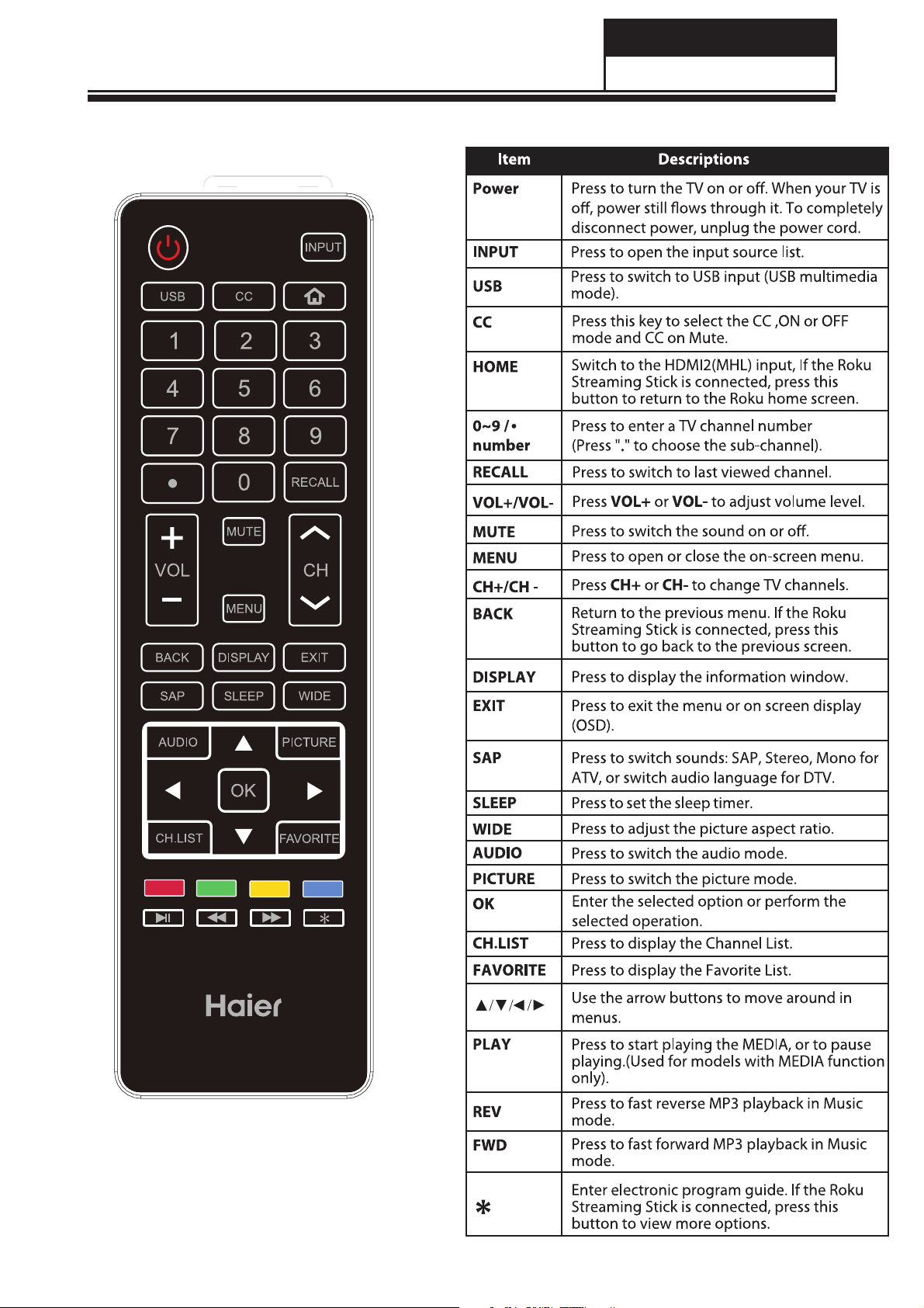
7-3 Using Remote Control
Service Manual
Model No.: 32E2000
- 27 -
Page 29

Service Manual
Model No.: 32E2000
8. Electrical Parts
8-1 System Block Diagram
1
2
3
4
TP.MS3393.PB812
A A
LVDS OUT
LVDS(8bit)
USB0 IN
USB0
LINE OUT
EXT LINEOUT
DDR2
SPI Flash
16Mbits
B B
HDMI2&MHL IN
HDMI2
HDMI2
L
MHL
AMPLIFIER
R
HDMI3 IN
HDMI3
HEADPHONE
C C
VGA IN
VGA
MSD3393LU
IIC,IF,AGC
TUNER
PC AUDIO IN
YPBPR&CVBS
YPBPR/CVBS AUDIO IN
COAX OUT
D D
1
2
3
4
- 28 -
Page 30

Service Manual
Model No.:32E2000
1
A A
FB1
!
CNB1
B B
C
D D
2
!
1
L
5
~
T3.
AL 250V
1
3
N
LCB1
1
!
NT CB1
D1
GD
G
2
2
!
!
NC
!
1
!
H
1
H
V
Y B
C
1
GN D
CYB2
SB2
H S
1
2
2
NC NC
4
!
!
M OV B1
B
L
2
C
2
3
SGN D
N
C
HSB3
H
S
1
2
1
2
12V
4
!
!
!
RB 1
RB 2
3
RB 3
RB 4
CX B1
CX B2
!
!
D3
G
ML 1
My
ar
l
3
L
Vbridge
DB2
DB1
B
D
D
3
4
B
12V
4
L
1
RB
C
N
RB1 42
NC
R O
B
NC
CB 111
SGN D
B101
U
1
G
2
CO
BR
O
!
NC3CS
C
N
PCB 101B
CB 103
RB 104
3 4
SGN D
U
B802
1
PIN1
GAT E
G
N D
P
IN4
PW M -REF
8 16
RB
PIN1
GA
T E
CB8 0
1
CB 802
D
G
N
PIN4
GN D
10
VIN
DIM
2
9
GAT E
OVP
3
8
GND
OM P
C
7
4
FB
CS
5
6
ISE
T
REF
GN D
B801
U
I
P
N8
1
8
P
W M
VI
N
2
7
GAT E
OVP
3
6
GN D
COM
P
5
4
CS
FB
NC
I
N5
P
PIN6
CB8 12
CB8 03
CB
5 RB804
8 0
5
Vbridge
+
E
1
41
L
RB1 01
RB1 02
6
T E
GA
N D
5
C
V
C
M P
4
CB 101
RB 103
NC
D
SG
N
EB8 04
PIN
8
OVP
N
PI
6
PIN5
CB8 1
1
GA
RB8 01
PW M
CB8 07
GN D
CB 806
GN D
8 05
RB
CB804
GN D
B
RB 121RB 123
CB 114
D
N
SG
6
RB
1 0
07
RB1
QB102
V
C C
RB
5
1 0
CB 102
VBL
RB
8 07
T E
N
C
DB805
I
-
M
D
OVP
3
RB80
RB806
E
L
D -FB
D
06
1
B
QB101
G
G
RB1 09
1
08
RB
SG
RB1 10
2
ZB1 01
2
113
C
N
3
CY B3
D
SGN
!
L
B802
BB8 02
C
N
01
LB8
NC
BB8 01
D
QB8 01
G
NC
S
RB8 08
RB8 2
1
GND
RB 818
RB 819
RB 820
6
CB1 18
N
!
1
TB1 01
RB 124 R B122
AK
D
D
S
S
RB 148
N D
H
CB8 09
3
HV
1
BB1 0
6
CB1 16
5
12V
AK
N
C
CB 113
DB 104AKDB 105
NC
N
C
RB 116
+
PCB 101A
E
B106
SGN
D
GN D
GN D
RB8
2
1
CB
8 10
DB8
01
RB8 14
+
EB 803
EB 801
OVP
S
RB 810
LED-FB
CN B805
G
N D
B8
1
0
CN
1
2
1
2
L
RB8 45
LED
-FB
C
11
DB102
DB1 03
7
1 17
CB
+
10
101
D
B
EB 101
N
8
9
12
KA
ED +
C
N D
G
RB131
12V
RB
1 32
RB
1 33
!
CB1 09
CB1 10
R
UB102
LED-F
B
LED +
AK
DB 804
+
NC
GN D
RB 837
RB 838
C
0
N B
6
8
CN B80
2
123
1
2
LED
-FB
LED
+
CB8 2
1
NC
L
ED +
7
5
2
RB1
RB1 26
RB
127
1
28
RB
VBL
+
+
EB 104
EB 105
NC
RB 140
GN D
RB
1 29
1
RB
30
12V
+
EB1 02
12V
RB 111
RB 112
NC NC
VBL
RB1 35
RB1 34
RB 839
CN
B2
12V
2
1
GND
RB 840
8
- 29 -
C
8-2 Circuit Diagram
1
Model Name:
DR AW
CH
2
3
4
5
6
7
.PB812B 14125
TP.MS 3393
N
:
K
:
D
'
VER S
O N:
I
0
V1.
20
14/8/14
E:
DA
T
DAT E:
2014 /8/14
8
Page 31

Service Manual
Model No.: 32E32000
1
A A
C2
B B
12V
GND
10uF
NC/1uF
100Kohm
C18
2
1
5
R18
EN
5V_ST B
CL 1
LC1117CL TR33
0.1uF
R1
U2
BS
4.5V~18V INPUT
VFB = 0.6V
500KHZ
IN
EN4GND
SYH112ADC
UL 1
VI3VO
1
GND
3
0ohm
C1
0.1uF
L1
6
LX
3
FB
2
2
4
A D J
VO
C22
GND
CTD0504-4R7- M
NC/22pF
47Kohm
6K2ohm
0.1uF
10uF
470uF
CL 2
NC/0.1uF
10uF
R23
R25
GND
3V3_S T B
CL 3
5V_ST B
℃
3V3_S T B
4
+5V
TEST
+
E2
C21
C20
GND
5
P O W _E N
10Kohm
10Kohm
6
3V3_S T B
RE 4
RE 5
RB5
BL _EN PW M-REF
100ohm
RB9
510ohm
5V_M
UL 2
VI3VO
CL 5
GND
0.1uF
LC1117CL TR18
A D J
VO
1
7
5V_ST B 5V_M
RM33
QM31
GND
PW M -DIMPW M /AD J
2
4
10uF
NC/0.1uF-0402-Y5V-+80%-20%-16V
RM34
4K7ohm
KMBT3904
100Kohm
W PM2341A-3/TR
NC/0.1uF
1V8_DDR
CL 6
GND
QM32
CL 7
8
CM32
GND
C C
PVCC
NC/10uF
5V_ST B
CD1
10uF
0.1uF
10Kohm
D D
1
UD1
4
RD1
CD2
1
EN
SYH407AAC
GND
2
GND GND
2
LD1
SW3VIN
5
FB
RD3
RD2
12K4ohm
13Kohm
G N D
10uF
0.1uF
CTD0403-6R8- M
1.15V_STB
1.15V_STB
TEST
CD5
CD4
CD3
3
4
3K3ohm
2K2ohm
KMBT3904
P O W _E N
5
RM6
GND GND
RM1
RM3
QM2
RM5
4K7ohm
200Kohm
ME2325- G
NC/10uF
0.1uF
6
S
QM1
G
0ohm
NC/0ohm
7
VCC-PANEL
D
CM6
CM2
GND
R12V
PVCC12V
R5V
PVCC5V_ST B
8
- 30 -
Page 32

Service Manual
1
1
2
2
3
3
4
4
5
5
6
6
7
7
8
8
D D
C C
B B
A A
PWM/ADJ
MHL_CABLE-DET
AMP-MUTE
AU_VRM
IF_AGC
VIFP
VIFM
AU_VAG
1.15V_STB
GIN1M
HD1_SOG
HD1_Pr
HD1_Y
HD1_Pb
VGA_RIN
VGA_GIN
VGA_BIN
GIN0M
VGA_HS
VGA_VS
AV_LIN
AV_RIN
HDMI-ARC
HDMI2_SCL
HDMI2_SDA
HDMI2_RXC_N
HDMI2_RXC_P
HDMI2_RX0_N
HDMI2_RX0_P
HDMI2_RX1_N
HDMI2_RX1_P
HDMI2_RX2_N
HDMI2_RX2_P
HOTPLUG1'
HDMI1_SCL
HDMI1_SDA
HDMI1_RXC_N
HDMI1_RXC_P
HDMI1_RX0_N
HDMI1_RX0_P
HDMI1_RX1_N
HDMI1_RX1_P
HDMI1_RX2_N
HDMI1_RX2_P
HDMI3_SCL
HDMI3_SDA
HDMI3_RXC_N
HDMI3_RXC_P
HDMI3_RX0_N
HDMI3_RX0_P
HDMI3_RX1_N
HDMI3_RX1_P
HDMI3_RX2_N
HDMI3_RX2_P
HOTPLUG2'
HDMI-CEC
UART-TX/DDC
UART-RX/DDC
REMOTE
RESET_H
SPI_CSN
SPI_SCK
SPI_SDI
SPI_SDO
RXO2_N
RXO3_P
RXO3_N
RXO2_P
RXO0_N
RXO1_P
RXO1_N
RXO0_P
RXE3_P
RXE2_N
RXE1_P
RXE1_N
RXE0_N
RXE0_P
RXE2_P
RXE3_N
RXEC_N
RXEC_P
M_SCL
M_SDA
XTALI
XTALO
SPDIF_OUT
POW_EN
PC_LIN
PC_RIN
1.15V_STB
1V8_DDR
3V3_STB
GND
1.15V_STB
AVDD5V_MHL
1V8_DDR
1.15V_STB
GND
USB0_DM
USB0_DP
GND
AV_IN
VCOM
KEY
BL_EN
LVA0M
70
SOGIN1
22
BIN1P
21
GIN1M
24
GIN1P
23
CVBS0
28
CVBS1
27
AUL1
36
GIN0P
16
GPIO0/GPIO44
55
LVACKM
64
VDDC/DVDD_DDR_CMD54VDDIO_CMD
53
AVDD_MOD
5
RIN1P
25
HOTPLUG_C/D
80
LVA1P
67
LVB3P
71
DDCDB_CL
112
DDCDB_DA
111
GIN0M
17
IRIN
93
CEC
92
TEST
91
DDCA_CK
90
DDCA_DA
89
LVA3M62LVACKP
63
LVA2P
65
LVA2M
66
DP_P0
97
LVB2P
74
LVB2M
75
LVB1P
76
LVB1M
77
LCK/LVB0P
78
PWM0
83
AVDD_MOD
73
DM_P0
96
HOTPLUG_B
113
AVDD_5V
114
GND_EFUSE
115
RX0P_B
128
VIFP46VIFM47AUOUTR044IFAGC45XIN50AVDD3P3_DMPLL49XOUT
51
RX1N_B
1
RX1P_B
2
RX2N_B
3
RX2P_B
4
RXCN_A
6
RXCP_A
7
RX0N_A
8
RX0P_A
9
RX1N_A
10
RX1P_A
11
RX2N_A
12
RX2P_A
13
HSYNC0
14
BIN0P
15
RIN0P
18
VSYNC0
19
AVDD3P3_ADC
20
VCOM
29
CVBS_OUT1
30
VDDC
31
AVDD_AU33
32
VAG
37
AUL0
34
AUR1
35
AUR440AUOUTL3
41
AVDD_MOD
52
GPIO3/GPIO4758GPIO4/GPIO4859LVA3P
61
GPIO2/GPIO46
57
LVA0P
69
LVB3M
72
LVA1M
68
LDE/LVB0M
79
HOTPLUG_A
81
SPI_DO
84
SPI_DI
85
SPI_CZ
86
PWM1
82
VDDIO_DATA
105
DDCDC_CL
106
DM_P1
98
VDDC/DVDD_DDR_DATA
104
DP_P1
99
AVDD_MOD
100
DDCDA_DA
109
INT/GPIO64
94
VDDC/AVDDL_DVI
116
RESET
95
MHL_DET
110
DDCDC_DA
107
DDCDA_CL
108
E-PAD
129
VSYNC1
26
AUR0
33
AUOUTL043AUOUTR3
42
GPIO1/GPIO45
56
SPI_CK
87
RXCN_D
117
RXCP_D
118
RX0N_D
119
RX0P_D
120
RX1N_D
121
RX2N_D
123
RX2P_D
124
RX1P_D
122
RXCP_B
126
RX0N_B
127
RXCN_B
125
VRM
38
AUL4
39
SAR1
102
SAR0
101
SAR2
103
GPIO5/GPIO49
60
ARC
88
AVDD3P3_DADC
48
U1
MSD3393LU
GND
C14
NC/0.1uF-0402-X5R-20%- 16V
XTALI
XTALO
CF2
33pF-0402-NPO-5%- 50V
CF1
33pF-0402-NPO-5%- 50V
GND
GND
R99
1Mohm-0402-5%- 1/16W
RF4
NC/10Kohm-0402-5%- 1/16W
GND
PWM/ADJ
BL_EN
R26
4K7ohm-0402-5%- 1/16W
R2
4K7ohm-0402-5%- 1/16W
3V3_STB
CE#
1
SO
2
WP#
3
VSS4SI
5
SCK
6
HOLD#
7
VDD
8
UF1
GD25Q16BSIG
SPI_SCK
SPI_CSN
SPI_SDI
SPI_SDO
GND
CF7
0.1uF-0402-X5R-20%- 16V
GND
CF16
NC/0.1uF-0402-X5R-20%- 16V
GND
GND
3V3_STB
GND
CL8
1uF-0402-X5R-20%- 6.3V
CL9
1uF-0402-X5R-20%- 6.3V
1V8_DDR
GND
1.15V_STB
CD7
0.1uF-0402-X5R-20%- 16V
CD8
1uF-0402-X5R-20%- 6.3V
CD9
1uF-0402-X5R-20%- 6.3V
CD10
0.1uF-0402-X5R-20%- 16V
3V3_STB
CL17
0.1uF-0402-X5R-20%- 16V
GND
3V3_STB
CL18
NC/0.1uF-0402-X5R-20%- 16V
GND
CL10
NC/0.1uF-0402-X5R-20%- 16V
CL12
0.1uF-0402-X5R-20%- 16V
CL13
0.1uF-0402-X5R-20%- 16V
CL14
0.1uF-0402-X5R-20%- 16V
CL20
1uF-0402-X5R-20%- 6.3V
CL15
NC/0.1uF-0402-X5R-20%- 16V
C5
NC/1000pF-0402-X7R-10%- 50V
C6
NC/1000pF-0402-X7R-10%- 50V
R5
200Kohm-0402-5%- 1/16W
R6
200Kohm-0402-5%- 1/16W
CL11
0.1uF-0402-X5R-20%- 16V
3V3_STB
3V3_STB
3V3_STB
3V3_STB
GND
LINE_L_OUT
LINE_R_OUT
HOTPLUG3'
HDMI_DET
3V3_STB
3V3_STB
CVBS1_OUT
MHL_CD_EN
PANEL_EN
LED_RED
GND
AMP-LO'
AMP-RO'
AMP-LO'
AMP-RO'
Y1
24MHz-20PPM- 20PF-HC-49S-JWT
C3
2.2uF-0402-X5R-20%- 6.3V
R3
NC
3V3_STB
3V3_STB
RV17
4K7ohm-0402-5%- 1/16W
RV15
4K7ohm-0402-5%- 1/16W
5V_STB
UART-RX/DDC
UART-TX/DDC
UART-TX
TEST
UART-RX
TEST
VCOM
RI7
68ohm-0402-5%- 1/16W
CI7
0.047uF-0402-X7R-10%- 16V
GND
R07
NC/0ohm-0402-5%- 1/16W
GND
GIN1MRI37
68ohm-0402-5%- 1/16W
CI10
0.047uF-0402-X7R-10%- 16V
Model No.: 32E2000
- 31 -
Page 33

Service Manual
Model No.:32E2000
D
1
10Kohm
2
5K6ohm
0Kohm
2
3K
3
ohm
2K2ohm
C
14PIN-
1K2ohm
2.0-D-H-G
-B
-
N
/P
V
/M
/
N D
7/
K 6
G
K
K 5
K 4
12345678910111213
K5K
6
RK
9
B
CN6
R
D
/S
I
C-
0
1/C +
K
K 2/
K
K 3/V+
K3K4
RK6
RK8
RK
RK5
7
5V
N
RE D
G R N
G
14
GND
IR
K0K1K2
L
LE
ED_
D_G
R
RK3
RK1
RK2
LE
D_
R
C
K3
CK1
L
5V_STB
E
D_RED
RK4
RK11
510ohm
22ohm
1Kohm
4K
7
ohm
3
4K7o
KMBT39
1Kohm
0
4
4
L
33Ko
ED_R
hm
hm
E
D
R
K1
9
C
KE
K2
Y
3V3_STB
3V3_STB
RK23
IR
GND
CK6
RXO
0_N
7 8
R
XO
0_
P
RK15
R
K16
RE
M
OTE
VCC-PA
VCC-PA
G
ND
N
N
E
E
L
L
1 2
345
C
N
5
V
G
ND
CCPA
N
EL
GN
D
QK2
LE
D_G
5V_M
R
K2
0
1Kohm
4K7ohm
5
6
RXEC_N
RXEC_P
CF5
CF4
GN
7
D
RXE2_
R
G
RXE3_N
XEC_N
ND
N
25
29
27
24
28
26
30
R
G
R
RXE
XE
ND
XE
C_P
2_
3_
P
P
G
RXO
RXO
RXE
RXE
RXE
R
XO
ND
1_N
2_N
3_N
C_
1_
0_
N RXE
N
N
17
111213 14
15 16
1920212223
9 10
18
R
R
XE
XE
0_
1_
P
P
R
G
RXO
R
ND
XO
XO
C_P
3_
1_
2_
P
P
P
A
5V_STB
1
2
3
4
1
A A
LINE_L_OUT
LINE_R_OUT
2
CNA2
PJ-339
B B
R9 R10
C7
R11
LINE_OUTL
C8
R12
LINE_OUTR
C9 C10
GND
LOUT+
ROUT+
1
GND
6
RIN
4
C15
RSPK
2
EP_R
ERO
3
EP_L
ELO
C17
5
LSPK
7
LIN
3
RA11
GVDD PLIMIT
RA12
GND
4
C C
5
D D
6
1
AMP-LO'
GND
AMP-RO'
RA21
RA10
2
0.22uF-0402-Y5V-+80%-20%-16V
0.22uF-0402-Y5V-+80%-20%-16V
0.22uF-0402-Y5V-+80%-20%-16V
0.22uF-0402-Y5V-+80%-20%-16V
AVCC
AMP_MUTE/
CA6
CA8
RA8
CA27
5V_M
GND
CA28
AVCC
GND
CA15
GVDD
GND
PLIMIT
CA29
CA21
CA20
EP-IN
GND
3
4
CN18
4
LOUT+'
3
LOUTROUT-
2
1
ROUT+'
4PIN-2.54-D-H-G-B
CA30 CA32 CA33 CA34
CA18
RA1
UA1
1
SD
2
FAULT
3
LINP
4
LINN
5
GAIN0
6
GAIN1
7
AVCC
8
AGND
9
GVDD
10
PLIMIT
11
RINN
12
RINP
13
NC
PBTL14PVCCR
OB6220RVPA
556
6
CN7
3
LINE_OUTL
GND12
LINE_OUTR
NC/3PIN-2.0-D-H-G
RA9 RA33
RA34 RA35
GND
AMPVCC
AMPVCC
CA3
CA2
28
PVCCL
27
PVCCL
CA7
26
GND
BSPL
25
OUTPL
24
PGND
GND GND
23
OUTNL
CA12
22
BSNL
CA13
21
BSNR
20
OUTNR
19
PGND
GND
18
OUTPR
CA22
17
BSPR
16
AMPVCC
PVCCR
15
CA24
CA25
GND
7
0.22uF-0402-Y5V-+80%-20%-16V
0.22uF-0402-Y5V-+80%-20%-16V
0.22uF-0402-Y5V-+80%-20%-16V
0.22uF-0402-Y5V-+80%-20%-16V
UPZ2012E601-2R0TF(600ohm-2000mA)
UPZ2012E601-2R0TF(600ohm-2000mA)
UPZ2012E601-2R0TF(600ohm-2000mA)
UPZ2012E601-2R0TF(600ohm-2000mA)
7
9
AMP-MUTE AMP_MUTE/
AMPVCC
LA1
+
LBA1
LBA2
LA2
+
LA3
+
LBA3
GND
LA4
+
LBA4
889
RA32
RA31
GND
RA60 RA62
RA4
EP-IN
CA50
GND
RA22
AMPVCC
DA1
+
EA1
CA1 CA16
GND
-SZ
℃
NC/SK34A-SMA
CA4
CA9
CA5
CA11
CA10
CA14
CA17
CA19
NC/SCD54TL-220M
NC/SCD54TL-220M
NC/SCD54TL-220M
NC/SCD54TL-220M
NC/1uF-0603-Y5V-+80%-20%-16V
NC/1uF-0603-Y5V-+80%-20%-16V
NC/1uF-0603-Y5V-+80%-20%-16V
NC/1uF-0603-Y5V-+80%-20%-16V
1010111112
LOUT+
LOUTROUT-
ROUT+
EP_R
12V
12
7
8
D
C
B
A
8
- 32 -
Page 34

1
2
3
4
5
6
7
8
AV
1
A A
Service Manual
Model No.: 32E2000
B B
HD-AF05-S011
AV2
C
D D
HD-AF05-S011
HDMI1_
5V
1
RH3
RX2+
2
GND
GND
3
RX2-
4
1+
RX
5
G
ND
D
GN
6
RX
-
1
7
RX0+
8
G
ND
GND
9
RX0-
10
RXC
+
11
G
N
D
ND
G
1
2
R
X
-
C
1
3
CEC
CE
C
14
_A
HDMI
C
R
AR
H D M I
C
HDM
I1_SCL/
1
5
S
L
C
1
6
S
DA
17
GND
1
8
+5
V
1
9
D
HP
GN D
GN D
GN D
GN D
20
212223
HDMI1_SDA/
GND
HDMI1_5
H
OTPLUG1
RH15
RH16
H13
C
V
HDMI
1_RX2_
HDM
I1_R
HDMI1_RX
I1_RX
HDM
HDMI
1_RX0_
1_R
I
HDM
I
1_R
HDM
HDMI1_RXC_N
HDMI1_
SCL
I1_SD
HDM
G
N
D
P
X
N
2_
P
1_
1_N
P
X0_
N
P
XC_
A
HOTPLUG1
HDMI1_
QH1
CH9
D
GN
RH4
V
5
R
H5
RH
8
RH2
KMBT3904
5V
HDMI1_
RH1
HDMI1_SDA/
HDMI1_SCL/
HOTPLUG1'
GND
RH2
4
1
RX2
+
MHL_CD_SENSE
2
ND
G
3
RX2-
4
1
R
+
X
5
GN
D
D
GN
6
RX
1-
7
R
X0+
GN
8
D
GND
9
RX0-
10
RXC+
11
GND
ND
G
1
2
RX
C-
13
EC
C
CE
C
14
AR
H D M I
C
1
5
/
I2_S
HDM
CL
SCL
16
HDMI2_SDA/
SDA
G
1
7
ND
ND
G
8
1
HDM
I2_5V
+5V
HOTPLUG2
1
9
D
H
P
GN D
GN D
GN D
GN D
20
212223
HDMI2_R
X2_P
HDMI2_R
N
X2_
1_P
HDMI2_RX
HDMI2_R
N
X1_
HDMI2_R
X0_P
2_R
I
X0_
HDM
N
HDMI2_RX
C_P
X
HDMI2_R
N
C_
RH30
HDMI2_SCL
RH31
HDM
CH18
I2_SDA
GN
D
AVDD5V_CD
2
HDMI2_SDA/
RH25
SCL/
HDMI2_
RH27
HOTPLUG2'HOTPLUG
V
AVDD5V_MH
HDMI2_5
L
RH29
1
A A
B B
CT
RF
T
_INPU
C C
D D
SDC
NC/
NC/SDCL 1
D
NC
/ES
S
D
NC/E
5
4
3
GND
2
ND
G
1
1
CEC
NSE
CH15
2
TUNER_SDA
TUNER_SCL
hm
0
o
17
1005CR33
L
BAV99-
BR
608CR22JT(F)
RFT1
GND
GND
ND
G
ND
G
F
R
T
CT10
CT5
CT16
LT2
G
ND
S
3NJT
DCL 1005C3
T
C33NJ
S
1
005
DCL
J
TDF
CT28
RF_INPUT
T
L
4
GND
GND GND
HD
2
3
4K
7
o
ohm
4K7
GND
LT6
DF
DF
DT
1
GND
3V3_STB
hm
RT14
R
T17
100o
m
h
16
R
T
m
100oh
Kohm
750
3V3_
CT
3
GND
LT3
CT8
CT9
LT1
1.8VRF
0oh
m
RT3
T
DA_IF_AG C
IF_AGC
h
m
100o
LT9
CT24
3
I1_5
V
4
RT15
M_SDA
V3_
3
un
T
CL
M_S
RT1
1.8VRF
GN
D
CT1
24
23
25
Tun
GND
GN
D
_N
AS
SET
E
PAD GN D
R
1
_1
VDD_3P3
2
NP
LNA_I
3
LNA_INN
4
VDD_1P8_1
CT11
5
G
PO3
AGC_2/
_2
PO
6
AGC_1
TP_2/G
U
CT1
4
_O
F
IF_OUT N_2/GPO _17I
8
4
RH56
HDMI_DETHDM
RH55
22
CT4
VD D_1P8_3
IF_OUT N_19I
IFN
5
GND
YT1
6M
-20PF-HC-49S-SMD-JWT
1
19
20
21
TA L
XT AL_P
XT AL_N
18
CLK
OUT
_
GN D_X
17
SDA
16
SCL
15
VDD_IO
14
GND_DIG
_1
13
P
VDD_1P2
T
U
_O
F
VD D_3P3_211VD D_1P8_2
12
10
3V3_T
1.8VRF
un
CT15
C78
IFP
GND
5
6
UT
2
61
Mx
L6
T
UNER_SDA
TUNER_SCL
3V3_Tun
CT12
GND
CT2
SDCL 1005CR12JT DF
1005CR12JT
S
DCL
6
3V3_STB
IF_AGC
IFP
IFN
M 1005KF-121T06(120
FC
3V3_STB
RT18
RT12
RT10
DF
7
FT
2
CT25
o
hm-500mA)
10Kohm
0.22uF-0402-Y5V-+80%-20%-1
CT19
N
G
CT21
LT10
GND
CT22
NC/680ohm
GND
7
8
3V3_Tun
3
CT1
CT6
GND
6V
D
2
CT
7
VI
FP
CT1
8
CT32
VIFM
8
- 33 -
GND
RH14
I-C
HDM
EC
HDMI_ARC
CH14
HDMI-ARC
5V_ST
2
CH
6
SENSE
RH20
RH50
HDMI2
_5V
RH12
MHL_CD_SENSE
B
G N D
5
9
RH1
FLAG
3
RH18
2171WG-
AP
1
OUT
N
I
4
F
EN
LG
UH2
7
C
GND
RH10
MHL_CABLE
-DETMHL_CD_SE
V_STB
1
RH1
CH20
HDMI2_5
5
V
5V
AVDD
_C
RH59
RH60
GND
D
GND
1
2
3
4
5
6
7
8
Page 35

Service Manual
Model No.: 32E2000
1
A A
B B
UART-TX /DDC
UART-RX /DDC
2
100ohm
100ohm
3
11
RV16
12
VGA_SDA
13
HS_VG A
VS_VG A
14
RV18
15
VGA_SCL
RV11
RV12
RV14
RV13
100ohm
100ohm
10Kohm
10Kohm
GND
4
1716
AV7
WL HD-051A
GND
1
R
TXD
6
GND
2
G
SDA
7
GND
D B 15
3
HS
B
8
GND
4
VS
RXD
9
5V
5
SCL
DET
10
GND
GND
GND
VGA_VS
VGA_HS
CV5
CV9
5
RV4
RV1
75ohm
CV1
33ohm
33ohm
GND
RV6
6
CV4
VGA_RIN
CV6
VGA_GIN
7
AV8
PJ-325
8
GND
ERO
RSPK
LSPK
ELO
10Kohm
10Kohm
12Kohm
12Kohm
NC/12Kohm
NC/12Kohm
1
5
2
3
4
PC_RIN/
PC_LIN/
9
GND
RV19
RV20
RV21
GND GND
10
11
PC_RI N
CV19
CV20
PC_LI N
12
RV24
RV22
RV23
GND GND
75ohm
68ohm
RV2
CV2
RV7
CV7
GIN0M
USB_5V
USB_M
USB_P
RF1
F2
0ohm
NC/
5R1ohm
5R1ohm
5V_M
USB0_DM
RF41
USB0_DP
RF42
RV8
GND
RV3
GND
CV8
VGA_BIN
75ohm
33ohm
CV3
AV21
USB-042M-002DP
1
5V
2
DM
3
DP
4
GND
5
GND
6
GND
CF41
CF3
GND
GND
CI8
33ohm
75ohm
CI36
HD1_S O G
CI9
HD1_Y
220ohm
SPDIF_OU T
RF51
RF52
AV5
CF51
COAXSPDIF_OUT'
1
SPDIF
2
GND
CF52
AV1-8.4-17C
GND
HD1_P b
CI38
HD1_P r
NC/GQ-03-08
NC/0ohm
100ohm
AV26
1
2
3
4
5
SPDIF_OUT'
IR Transmitter
Vin
Vcc
GND
GND
GND
5V_M
RF2
COAX
RI34
CI2
RI1
RI36
RI32
75ohm
33ohm
GND
RI38
RI33
75ohm
33ohm
GND
AV_LI N
AV_RI N
Y _Y
GND
Y _Pb
Y _Pr
C C
AV3
1
L
2
GND
3
R
4
GND
CYB-3.2-2DW28B-1-100(R)
AV4
Y
GND
Pb
GND
D D
Pr
GND
AV3-8.4-07C
1
2
3
4
5
6
AV_L
GND
AV_R
GND
GND
AV6 NC/AV1-8.4-17C
AV9 NC/AV1-8.4-17C
Y _Y
Y _Pb
Y _Pr
AV_L
1
L
2
GND
GND
1
AV_R
R
2
GND
GND
AV_L
RI6
AV_L/
CI6
RI3
12Kohm
10Kohm
AV_R
RI5
CI5
AV_R/
RI2
12Kohm
10Kohm
GND
1
2
3
4
5
6
7
8
9
10
11
12
- 34 -
Page 36

8-3 Wiring Connection Diagram
Service Manual
Model No.: 32E2000
2
5
3
1
No. Connection
1 Connection wire for keypad
2 Connection wire for IR LED
3 Connection wire for speakers
4 LVDS wire
5 Connection wire for power
4
- 35 -
Page 37

Service Manual
Model No.: 32E2000
9. Measurements and Adjustment
9-1 Operation Guide
- 36 -
Page 38

Service Manual
Model No.: 32E2000
- 37 -
Page 39

Service Manual
Model No.: 32E2000
- 38 -
Page 40

Service Manual
Model No.: 32E2000
- 39 -
Page 41

Service Manual
Model No.: 32E2000
- 40 -
Page 42

Service Manual
Model No.: 32E2000
- 41 -
Page 43

Service Manual
Model No.: 32E2000
- 42 -
Page 44
Service Manual
Model No.: 32E2000
9-2 Factory Mode
1.1 Power on Upgrading
STEP 1:Make sure that the .bin file has been put under the root directory of USB
removable device.
STEP 2:
switched off ,re-power on .If the LED light turns out to be red alternating with
green ,it means the upgrading is on process .
The blinks goes to be slowly, when the burning flash has finished, it will to be the
success light.
1.1.1 Upgrading
The red light and the green light switch slowly, for one second once.
Red…green…red…green…
1.1.2 Upgrade successful
The light turns to be red for twice quickly, and the mains green for half second.
Red…red…green……red…red…green……
1.1.3 Failed
The red light and the green light switch quickly, for five times per second.
Red…green…Red…green…Red…green…Red…green…Red…green…
STEP 3:
could be finished.
Link the USB device to the TV mainboard , make sure the current is
Disconnect to the power and the connect to the power, then the upgrading
1.2 Factory Seng Upgrading
STEP 1:Make sure that the .bin le has been put under the root directory of USB
removable device.
STEP 2:
remote control to enter the factory seng.
STEP 3:
the picture 1.1:
STEP 4:
light turns out to be red alterna with green represents the upgrading has begun.
when the burning flash has ed, LED the red green alternang ashing light
slowly and the menu prompts to disconnect the power, as shown in re 1.3.
Link the USB device to the TV mainboard, press <MENU>+1147 of the
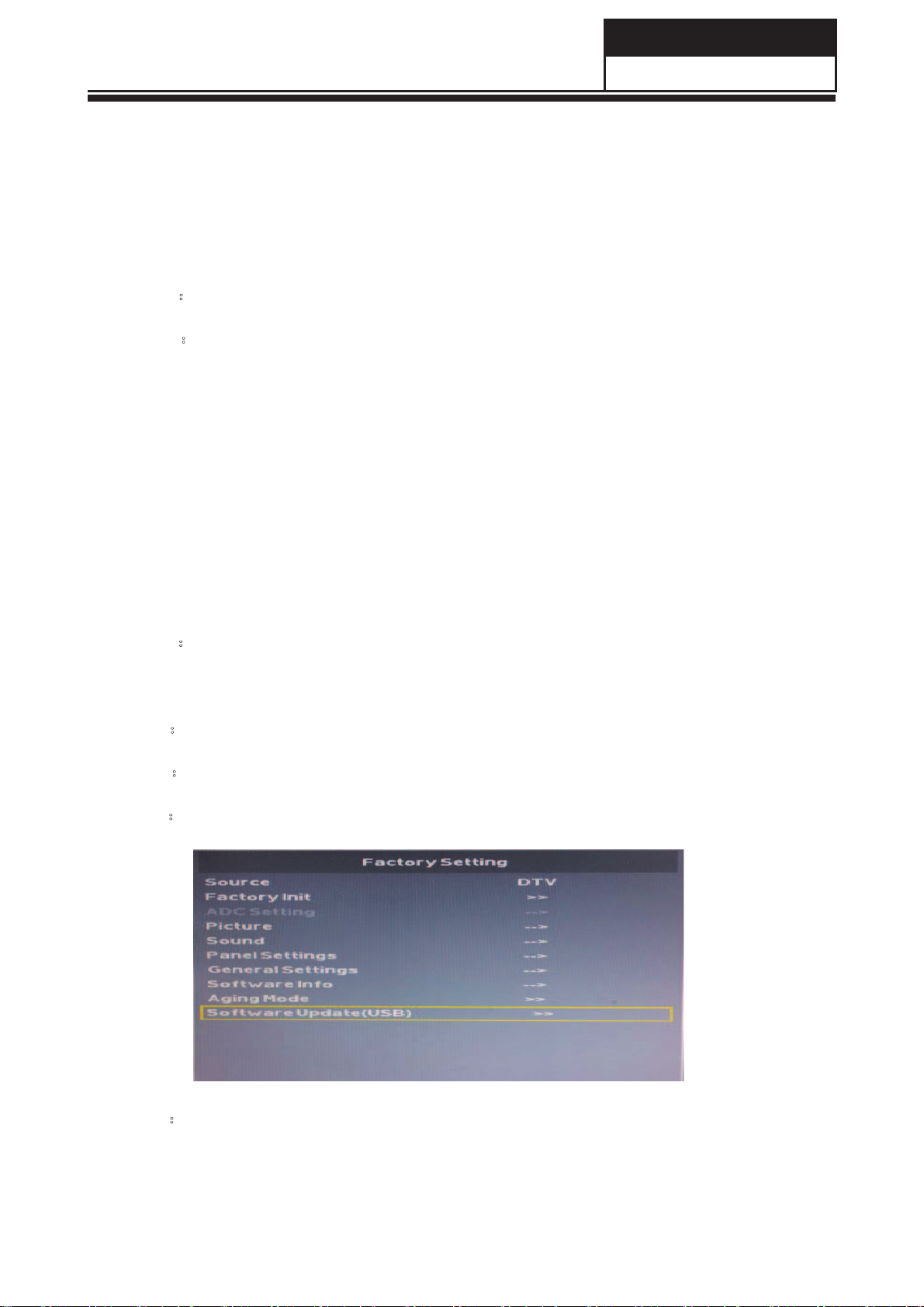
Search for the ‘Soware Upgrade(USB)’ item by the remote control ,just like
Picture 1.1
Enter the upgrading menu and chose ‘Yes’, as shown in re 1.2. The LED
- 43 -
Page 45

Service Manual
Model No.:32E200
9-3 Software Update
Picture 1.2
Software Update (USB)
Picture
STEP 5:Disconnect to the power and connect to the power, the upgrading could be
ed.
1.3
9-4 Hotel Mode
Hotel mode allows user to set certain default settings, limit access to certain controls and
adjustments so that settings cannot be altered by other people. See “Hotel Mode” on page
40 for more information.
- 44-
Page 46

Service Manual
Model No.: 32E2000
10. Troubleshooting
10-1 Simple Check
Please make these simple checks before calling service. These tips may save you time and money since
charges for receiver installation and adjustments of customer controls are not covered under your
warranty.
wolloF ot snoitcA dna kcehC ot smetIsmotpmyS
No power • Check if the TV’s AC power cord is plugged into a working power
outlet.
• Unplug the TV, and wait 60 seconds. Then reinsert plug into the
working power outlet and turn on the TV again.
No picture • Make sure correct input source is selected.
• Check antenna connection on the back of the TV to see if it is
properly connected.
• Possible broadcast station trouble. Try another channel.
• Adjust the picture contrast and brightness settings.
Good picture but no sound
Good sound but poor color • Adjust the contrast, color and brightness settings.
Poor picture • Poor picture quality may occur when an activated S-VHS camera or
Snowy picture and noise • Check the antenna connection.
TV not responding to remote
control
TV not working • Disconnect the TV from the power supply for 10 seconds, then
No le displayed in USB
mode
• Increase the volume level by pressing + button on the remote
control or VOL+ button on TV side control panel.
• Press button on the remote control to ensure mute is o.
camcorder is connected to your TV and the other peripheral at the
same time. Switch o one of the peripherals.
• Check whether the batteries are working. Replace if necessary.
• Make sure the remote control batteries are installed correctly.
• You can still use the control buttons on the side of your TV.
reconnect the TV. If the problem persists, contact authorised service
personnel for technical assistance.
• Make sure you select correct media type.
• Make sure the stored les are in supported format.
- 45 -
Page 47

Service Manual
Model No.: 32E2000
10-2-1 AC/DC Power Board Diagram
AC
input
EMI
filter
Rectifie
19V/24V/
32V/50V
output
AC/DC
Power convertor
Output
Output
Feed
LED driver
BL_ON
PWM_REF
PWM_DIM
filter
filter
back
10-2-2 AC/DC Power Supply Trouble
19V/24V/
32V/50V
output
12V
output
power amplifier
The main IC、
Screen voltage
and so on
LED
、
Go to
check
Main
board
function
Check the rectifier
Non output, IR indicator light slake
Y
Check if 12V、19V(24V/
32V/50V) output normal
N
Check if FB1 Open
N
Check EMI open or L N short
N
N
Check if EB1 voltage
about √2Vac
Y
Check if UB101 PIN5
voltage is about 15V
Y
Check if output short
N
Check the power
components
damage or not
Y
Check if RB101,
RB102 open
Change
UB101
Change short
components
N
YY
Y
Change damage
Change damaged
components
resistors
- 46 -
Page 48

10-2-3 LED driver Trouble
IR indicator light
up but backlight slake
Service Manual
Model No.: 32E2000
Correct
the LED
cable
Check if LED
output
short/open
Y
Remove
short/open
status
Y
Y
Check if LED output cable
is connect correction
N
Check PWM_DIM&PWM_REF&
BL_ON Control signal
Y
check is part of
the brightness is
in dim status
check is all of
the brightness is
in dim status
N
Check if UB801/UB802
PIN1 voltage is about 12V
Y
Check QB801/DB801
damage or not
Y
Change
QB801/DB801
10-2-4 DC/DC Power Supply Trouble
N
Y
Increase
brightness/check
if Sampling
resistor is right
N
Change
UB801/UB802
Check
Main
board
function
Check Pin2 of CNB2 for 12V
N
Check if the power
board is OK?
N
Repair the power board.
Repair the abnormal circuit :
1.5V_STB—check U2
2. 3V3_STB—check UL1
3.1.15V_STB–- check UD1
and peripheral components
Repair the abnormal circuit :
1. 5V_M—check power supply ,and
QM32 circuit
2. 1V8_DDR–- check UL2
Y
Check power on the TV board.
Check U2 for 5V_STB , UL1 for
3V3_STB and UD1 for 1.15V_STB
N
Power on , check CM32 for
5V_M,UL2 for 1.8V_DDR
N
Y
Y
Y
OK
- 47 -
Page 49

Service Manual
Model No.: 32E2000
10-3-1 Display Trouble (blurred screen )
blurred screen
Check if the cable is correct
and connected tightly
N
Y
Change the cable
for panel
Change panel
Repair this circuit
N
N
Check if the panel is OK
Check if the output circuit from
to the jack is normal
U1(MSD3393) damage
10-3-2 Display Trouble (white screen )
White screen
Y
U1(MSD3393)
Y
Software error or
Check if the voltage of panel power
supply is normal(depend on panel)
Check the circuit of QM1
Change U1(MSD3393)
N
N
- 48 -
Y
Check output signal
from U1(MSD3393)
Change the panel
or the cable to panel
Y
Page 50

10-3-3 Display Trouble (black screen)
Black screen
Check if BL_ON state is normal
Service Manual
Model No.: 32E2000
Check if the control circuit
between BL_ON and
N
Repair the circuit
BL_EN is normal ?
Change U1(MSD3393)
N
Y
Y
Check if the control circuit
between ADJ and
PWM/ADJ is normal ?
N
Repair the power supply
Y
Check if the power supply
for inverter is normal?
Check the inverter board
- 49 -
Page 51

Service Manual
Model No.: 32E2000
10-4-1 Audio Trouble
No sound
Check the AMP power
N
Check the power supply circuit
Check the control circuit
Check the circuit from U1
to AMP
Check the circuit between output jack
and AMP chip, Change AMP chip
Y
Check if PIN1 of the AMP chip
voltage is normal
N
Y
Check the input signal
N
Y
Check the output signal
N
Check the circuit from AMP to the jack
Y
- 50 -
Page 52

10-5-1 Function Trouble (TV video)
TV can’t search any
channel/no picture
Check input RF signal
N
Check the RF source
N
Check power supply circuit
N
Check IIC circuit Check IFP/IFN output signal
N
Check tuner and
peripheral components
10-5-2 Function Trouble (PC)
Y
Check tuner power
Check if IIC work
Check the circuit from
tuner to U1(MSD3393)
Service Manual
Model No.: 32E2000
Y
Y
Y
PC mode
Picture is not
in center
Do “auto adjust”
process
Missing color,
deflection color
Check if the R.G.B
input signal of U1
Y
Do “reset” process
on the menu
is normal
Check the circuit of
N
R.G.B input
Do “reset” process
on the menu or
the input mode
can’t be supported
Picture
dithering
Check if the signal of
V-sync,H-sync is OK
Y
Check the circuit
of VS.HS
No signal
N
Check the circuit
of VS.HS
10-5-1 Function Trouble (HDMI、YPbPr 、CVBS )
HDMI , YPbPr , CVBS
Check the signal at the jack
Check the external source
Check the circuit from jack to
U1(MSD3393)
N
- 51 -
YN
Check the signal on the
Corresponding of U1
Y
Change U1(MSD3393)
 Loading...