

Page 1

CAUTION READ
THIS MANUAL CAREFULLY TO DIAGNOSE
EFORE OFFERING
SERVICE MANUAL
Colour Television
TROUBLE CORRECTLY B
SERVICE .
Haier model:
21FA11-AM
Customer model:
HTAF21S
Page 2

.
CONTENTS
1. Safety precautions……………………………………………………………..……………3
2. TV block diagram……………………………………………………………………..…….4
3. Replacement of memory IC………………………………………………………….……5
4. Service adjustment……………………………………………………………..…………...5
5. ICs functional description…………………………………………………………………8
6. Test point waveform………………………………………………………………………10
7. All ICs voltages……………………………..……………………………………………….10
8. Purity / convergence adjustment………………………………………………………11
2
Page 3
.
1. SAFETY PRECAUTIONS
1. The design of this product contains special hardware, many
circuits and components especially for safety purposes. For
continued protection, no changes should be made to the
original design unless authorized in writing by the
manufacturer. Replacement parts must be identical to those
used in the original circuits. Service should be performed by
qualified personnel only.
2. Alterations of the design or circuitry of the products should
not be made. Any design alterations or additions will void the
manufacturer’s warranty and will further relieve the
manufacturer of responsibility for personal injury or property
damage resulting therefrom.
3. Many electrical and mechanical parts in the products have
special safety-related characteristics. These characteristics
are often not evident from visual inspection nor can the
protection afforded by them necessarily be obtained by using
replacement components rated for higher voltage, wattage,
etc. Replacement parts which have these special safety
characteristics are identified in the parts list of Service
manual. Electrical components having such features are
identified by shading on the schematics and by ( ! ) on
the parts list in Service manual. The use of a substitute
replacement which does not have the same safety
characteristics as the recommended replacement part
shown in the parts list of Service manual may cause shock,
fire, or other hazards
4. Don’t short between the LIVE side ground and
ISOLATED (NEUTRAL) side ground or EARTH side
ground when repairing. Some model’s power circuit is
partly different in the GND. The difference of the GND is
shown by the LIVE: ( ) side GND, ISOLATED
(NEUTRAL): ( ) side GND and EARTH: ( ) side GND.
Don’t short between the LIVE side GND and ISOLATED
(NEUTRAL) side GND or EARTH side GND and never
measure with a measuring apparatus (oscilloscope etc.) the
LIVE side GND and ISOLATED (NEUTRAL) side GND or
EARTH side GND at the same time. If above note will not be
kept, a fuse or any parts will be broken.
5. If any repair has been made to the chassis, it is
recommended that the B1 setting should be checked or
adjusted (See ADJUSTMENT OF B1 POWER SUPPLY).
6. The high voltage applied to the picture tube must conform to
that specified in Service manual. Excessive high voltage can
cause an increase in X-Ray emission, arcing and possible
component damage, therefore operation under excessive
high voltage conditions should be kept to a minimum, or
should be prevented. If severe arcing occurs, remove the AC
power immediately and determine the cause by visual
inspection (incorrect installation, cracked or melted high
voltage harness, poor soldering, etc.). To maintain the proper
minimum level of soft X-Ray emission, components in the
high voltage circuitry including the picture tube must be the
exact replacements or alternatives approved by the
manufacturer of the complete product.
7. Do not check high voltage by drawing an arc. Use a high
voltage meter or a high voltage probe with a VTVM.
Discharge the picture tube before attempting meter
connection, by connecting a clip lead to the ground frame
and connecting the other end of the lead through a 10kΩ 2W
resistor to the anode button.
8. When service is required, observe the original lead dress.
Extra precaution should be given to assure correct lead
dress in the high voltage circuit area. Where a short circuit
has occurred, those components that indicate evidence of
overheating should be replaced. Always use the
manufacturer’s replacement components.
9. Isolation Check
(Safety for Electrical Shock Hazard)
After re-assembling the product, always perform an isolation
check on the exposed metal parts of the cabinet (antenna
terminals, video/audio input and output terminals, Control
knobs, metal cabinet, screw heads, earphone jack, control
shafts, etc.) to be sure the product is safe to operate without
danger of electrical shock.
10. The surface of the TV screen is coated with a thin film which
can easily be damaged. Be very careful with it when handle
the TV. Should the TV screen become soiled, wipe it with a
soft dry cloth. Never rub it forcefully. Never use any cleaner
or detergent on it.
(1) Dielectric Strength Test
The isolation between the AC primary circuit and all metal
parts exposed to the user, particularly any exposed metal
part having a return path to the chassis should withstand a
voltage of 3000V AC (r.m.s.) for a period of one second.
(…Withstand a voltage of 1100V AC (r.m.s.) to an appliance
rated up to 120V, and 3000V AC (r.m.s.) to an appliance
rated 200V or more, for a period of one second.)
This method of test requires test equipment not generally
found in the service trade.
(2) Leakage Current Check
Plug the AC line cord directly into the AC outlet (do not use
line isolation transformers during this check). Using a
“Leakage Current Tester”, measure the leakage current from
each exposed metal part of the cabinet, particularly any
exposed metal part having a return path to the chassis, to a
known good earth ground (water pipe, etc.). Any leakage
current must not exceed 0.5mA AC (r.m.s.).
However, in tropical area, this must not exceed 0.2mA AC
(r.m.s.).
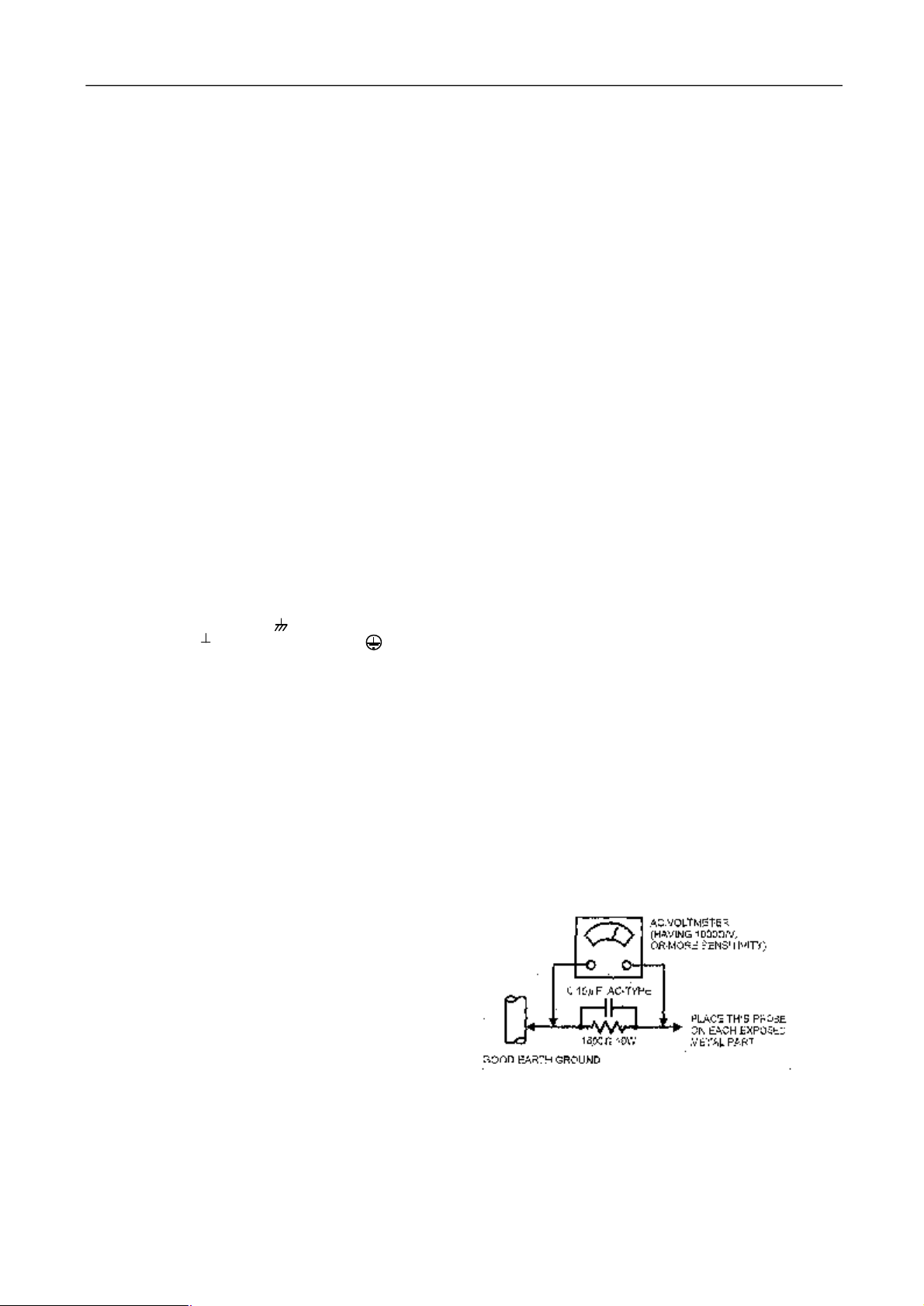
●Alternate Check Method
Plug the AC line cord directly into the AC outlet ( do not use
a line isolation transformer during this check.). Use an AC
voltmeter having 1000 ohms per volt or more sensitivity in
the following manner. Connect a 1500Ω 10W resistor
paralleled by a 0.15μF AC-type capacitor between an
exposed metal part and a known good earth ground (water
pipe, etc.). Measure the AC voltage across the resistor with
the AC voltmeter. Move the resistor connection to each
exposed metal part, particularly any exposed metal part
having a return path to the chassis, and measure the AC
voltage across the resistor. Now, reverse the plug in the AC
outlet and repeat each measurement. Any voltage measured
must not exceed 0.75V AC (r.m.s.). This corresponds to
0.5mA AC (r.m.s.).
However, in tropical area, this must not exceed 0.3V AC
(r.m.s.).
This corresponds to 0.2mA AC (r.m.s.)
3
Page 4
.
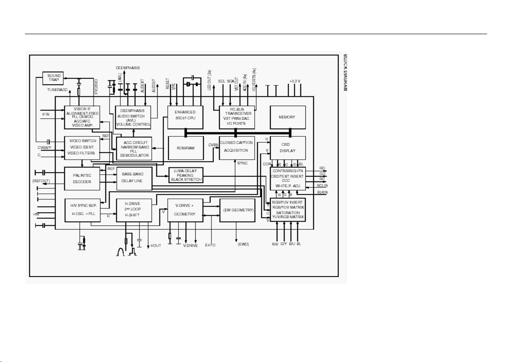
2. Block diagram TDA8378PS/N2 series with mono intercarrier sound demodulator
4
Page 5

3. REPLACEMENT OF MEMORY IC
1. MEMORY IC.
This TV uses memory IC. In the memory IC are memorized data for correctly operating the video and deflection
circuits.
2. PROCEDURE FOR REPLACING MEMORY IC
(1) Power off
Switch the power off and unplug the power cord from AC outlet.
(2) Replace IC
Be sure to use memory IC written with the initial data values.
(3) Power On
Plug the power cord into the AC outlet and switch the power on.
(4) Check and set SYSTEM default value:
1) Press “MUTE” à “CALL” à “-\--“ à “CALL” à “MUTE” buttons in sequence to enter into factory
status.
2) If the memory IC haven’t been written with the initial data, press [Program+] / [Program-] to select item
INIT and press [VOLUME+] / [VOLUME-] to start initialize memory IC.
3) Check the setting value of the SYSTEM default value of Table below. If the value is different, select
items by [Program+] / [Program-] keys and set value by [VOLUME+] / [VOLUME-] keys.
4) Press “EXIT” button to return to the normal screen.
4. SERVICE ADJUSTMENT
Specific operation: use remote controller
Press “MUTE” à “CALL” à “-\--“ à “CALL” à “MUTE” buttons in sequence to enter into factory mode.
Press [Program+] / [Program-] to select items and press [VOLUME+] / [VOLUME-] key, to make data adjustment
of corresponding factory menus.
Press “EXIT” key to exit factory mode.
Focus adjustment
1. Receive a crosshatch signal.
2. While watching the screen, adjust the FOCUS VR on the FBT to make the vertical and horizontal lines as
fine and sharp as possible.
Geometrical adjustment
Receive PAL standard complete pattern signal.
Adjustment steps:
a) Adjust VSL, to the centre horizontal line just appears from half bottom shadow.
b) Adjust VAM, to get 92% of vertical picture contents would be displayed on CRT.
c) Adjust VSH, the centre horizontal line corresponds to CRT vertical centre.
d) Adjust SCL, to the linearity of P card field is in proper condition.
e) Adjust HSH, to get the picture horizontal centre correspond to CRT horizontal centre.
Receive NTSC signal and repeat above adjustment.
AGC Adjustment
Receive 60dBμ (1mV) VH colour bar pattern signal.
Select TOP item.
Adjust value, to noise reduce gradually and just disappeared point.
CRT cut off and white balance adjustment
a) CRT cut off adjustment
1. Select item VG2B, then adjust value to 32.
2. PRESS “0” key, when the screen shows”VG2” adjust the SCREEN control on Fly back transformer to
make the screen show alternating flashing characters of “INSIDE HIGH INSIDE LOW”.
b) White balance adjustment
1. Receive a Black and White pattern.
2. Adjust WRP, WRG, WRB items to get colour temperature 9300K ±3 JND.
5
Page 6

1=Enable (Can only be selected either RGB and DVD)
Adjustable Items
Direct access key Items Description Preset Remark
“1” 5/6HSH Horizontal shift ON A
“2” 5/6VSL Vertical slop 32 A
5/6VAM Vertical amplitude 23 A
5/6SCL S-correction 17 A
5/6VSH Vertical shift 27 A
5/6VOF OSD Vertical offset 37 A
HOF* OSD Horizontal offset 42 A
“3” RED Black level offset R 32 A
GRN Black level offset G 32 A
WPR White point R 30 A
WPG White point G 26 A
WPB White point B 38 A
“4” TOP AGC Take-over point 20 A
VOL Volume 42
9860 Sub-volume of TDA9860/59 18
HDOL Cathode drive level 59
AGC IF AGC speed 1
VG2B VG2 Brightness 42
IFFS 2
“5” Picture preset 1
0CON Listen: Contrast 0 A
0BRI Listen: Brightness 0 A
0COL Listen: Colour 50 A
0SHP Listen: Sharpness 50 A
1CON Soft: Contrast 45 A
1BRI Soft: Brightness 45 A
1COL Soft: Colour 50 A
1SHP Soft: Sharpness 50 A
“6” Picture preset 2
2CON Standard: Contrast 75 A
2BRI Standard: Brightness 50 A
2COL Standard: Colour 50 A
2SHP Standard: Sharpness 60 A
3CON Dynamic: Contrast 85 A
3BRI Dynamic: Brightness 60 A
3COL Dynamic: Colour 60 A
3SHP Dynamic: Sharpness 80 A
NOTE: THE ITEMS WITH REMARK “A” IS ADJUSTABLE DATA.
Optional data
1. OP1
Bit Function Description Preset Remark
Bit 0 VG2_MODE 1= 0 EA
Bit 1 YPRPB 1=Enable 1 EA
Bit 2 SUPERWOOFER Translucence OSD manual 1=Enable 0 EA
Bit 3 WOOFER_VOL
Bit 4 AV2 1=Enable 1 EA
Bit 5 SVHS 1=Enable 0 EA
Bit 6 DVD 1=Enable 0 EA
Bit 7 RGB 1=Enable 1 EA
6
0 EA
Page 7

2. OP2
Bit Function Description Preset Remark
Bit 7 FSL 1=21dBμV 0=26dBμV 0 EA
Bit 6 SOY 1=Enable 1 EA
Bit 5 ARABIC_SET 1=Enable 0 EA
Bit 4 FARSI_SET 1=Enable 0 EA
Bit 3 CYRILLIC_SET 0 EA
Bit 2 EUROUP_SET 1=Enable 1 EA
Bit 1 AUTO_SOUND 1 EA
Bit 0 AVL 1=Enable 1 EA
3. OP3
Bit Function Description Preset Remark
Bit 7 RUSSIA 1=Enable 0 EA
Bit 6 ITALY 1=Enable 0 EA
Bit 5 GERMANY 1=Enable 0 EA
Bit 4 FRANCE 1=Enable 0 EA
Bit 3 RUTKISH 1=Enable 0 EA
Bit 2 ARABIC 1=Enable 0 EA
Bit 1 FARSI 1=Enable 0 EA
Bit 0 ENGLISH 1=Enable 1 EA
4. OP4
Bit Function Description Preset Remark
Bit 6 HALFTONE 1=Enable 1 EA
Bit 5 IDENT_SENSITIVE 1 EA
Bit 4 HCO 1=Enable 0 EA
Bit 3 LOGO 1 EA
Bit 2 TILT 0 EA
Bit 1 SPANISH 1 EA
Bit 0 ROMANIA 0 EA
5. OP5
Bit Function Description Preset Remark
Bit 7 STORE_AV 1= Enable 1 EA
Bit 6 OSO 1= Enable 0 EA
Bit 5 SOFR_CHANGE 1=Enable 0 EA
Bit 4 FADE 1=Enable 0 EA
Bit 3 SOUND_M 1= Enable 0 EA
Bit 2 SOUND_I 1= Enable 0 EA
Bit 1 SOUND_BG 1=Enable With DVD select 1 1 EA
Bit 0 SOUND_DK 1=Enable 0 EA
6. OP6
Bit Function Description Preset Remark
Bit 7 RESERVE 1=Enable 0 EA
Bit 6 POR_WHEN_BLUE 1=Enable 1 EA
Bit 5 MENU_MIDLINE 1=Enable 1 EA
Bit 4 MENU_BLUE 1=Enable 1 EA
Bit 3 CHILDLOCK 1=Enable 1 EA
Bit 2 16_9 1=Enable 0 EA
Bit 1 BLUE_SCREEN 1=Enable 1 EA
Bit 0 LOGO_LISTEN 1 EA
7
Page 8

7. OP7
Bit Function Description Preset Remark
Bit 7 FMWS 1=Enable 1 EA
Bit 6 HOTEL 1=Enable 0 EA
Bit 5 PROG_ID 1=Enable 0 EA
Bit 4 LED 1=Enable 0 EA
Bit 3 TWIST 1=Enable 0 EA
Bit 2 BYELORUSSIAN 1=Enable 0 EA
Bit 1 UKRANIAN 1=Enable 0 EA
Bit 0 AV1 1=Enable 1 EA
8. OP8
Bit Function Description Preset Remark
Bit 6 DIRECT_SWITCH_ON 1=Enable 0 EA
Bit 5 INNER_DVD 1=Enable 1 EA
Bit 4 PROG_FREQ 1=Enable 0 EA
Bit 3 FAST_BAR 1=Enable 1 EA
Bit 2 AUSTRALIA 1=Enable 0 EA
Bit 1 FREQ 1=Enable 1 EA
Bit 0 9860 1=Enable 0 EA
Note:Don’t adjust any OPTION items, please inform the engineer about any change.
5. ICs functional description
1. N201 UOC OM8378
SYMBOL PIN DESCRIPTION
STAND BY output. 1 In STAND BY mode, low level (Power OFF).
For Power ON this pin will be high.
SCL 2 I2C-bus clock line
SDA 3 I2C-bus data line
TUNING 4 tuning Voltage (Vt) PWM output
KEY 5 Control keys input
SYSTEM 6 TV system control
VOL 7 Sound Volume control PWM output
MUTE 8 Sound mute output
VSSC/P 9 Digit ground for μ-controller core and periphery
CTL 10 DVD power control
STANDBY 11 STANDBY control
VSSA 12 Analog ground of digital ground of TV-processor
SECPLL 13 Internally connected
VP2 14 2nd supply voltage TV-processor(+8V)
DECDIG 15 decoupling digital supply of TV-processor
PH2LF 16 Phase-2 filter
PH1LF 17 Phase-1 filter
GND3 18 Ground 3 for TV-processor
DECBG 19 Band gap decoupling
AVL/EWD 20 Automatic volume levelling
VDRB 21 Vertical drive B output
VDRA 22 Vertical drive A output
IFIN1 23 IF input 1
IFIN2 24 IF input 2
8
Page 9

IREF 25 Reference current input
VSC 26 Vertical sawtooth capacitor
TUNER AGC 27 Tuner AGC output
AUDEEM/SIFIN1 *1 28 Audio deemphasize or SIF input
DECSDEM/SIFIN2 29 Decoupling sound demodulator
GND2 30 Ground 2 for TV processor
SNDPLL/SIFAGC *1 31 Narrow band PLL filter
AVL 32 Automatic Volume Levelling
HOUT 33 Horizontal output
FBISO 34 Flyback input/sandcastle output
AUDEXT 35 External audio output
EHTO 36 EHT/over voltage protection input
PLL IF 37 IF-PLL loop filter
IFVO/SVO 38 IF video output / selected CVBS output
VP1 39 supply voltage TV processor
CVBS INT 40 internal CVBS input
GND1 41 ground for TV processor
CVBS/Y 42 CVBS/SVHS(Y) input
CHROMA 43 SVHS (C) input
AUDOUT 44 Audio output
INSSW2 45 YUV insertion input
R2/VIN 46 R input / V (R-Y) input / PR input
G2/YIN 47 G input / Y input
B2/UIN 48 B input / U (B-Y) input / PB input
BCLIN 49 Beam current limiter input
BLKIN 50 Black current input
RO 51 Red output
GO 52 Green output
BO 53 Blue output
VDDA 54 Analog supply of Closed Caption decoder and digital supply of TV-processor (3.3 V)
VPE 55 Ground
VDDC 56 Digital supply to core (3.3 V)
OSCGND 57 Oscillator ground supply
XTALIN 58 Crystal oscillator input
XTALOUT 59 Crystal oscillator output
RESET 60 Ground
VDDP 61 Digital supply to periphery (+3.3 V)
P1.0/INT1 62 AV1 / AV2 mode Output.
P1.1/T0 63 AV /S-VHS mode Output.
P1.2/INT0 64 Remote control signal input.
Note
Pin TV SVHS AV1 AV2
62 1 0 0 1
63 1 1 0 0
2. N202 24C08/PCF8598
PIN Function
1 GND
2 GND
3 Upper resistance
4 GND
5 SDA data wire
6 SCL clock wire
7 GND
8 +5V Power
3. N601: Sound power amplify (AN7522N)
Symbol PIN Function Symbol PIN Function
Vcc 1 Power supply GND 7 ground
Out 1 (+) 2 Ch 1 output (+) In 2 8 Ch 2 input
GND(out 1) 3 Ch 1Ground VOL 9 Volume Control
Out 1 (-) 4 Ch 1 output (-) Out 2 (-) 10 Ch 2 output (-)
Standby 5 Mute input GND(out 2) 11 Ch 2 Ground
9
Page 10

TDA
8378
IN53
TDA
8378
N52
TDA
8378
IN51
TDA
8378IN33
TDA
8378IN34
In 1 6 Ch 1 input Out 2 (+) 12 Ch 2 output (+)
4. N301: Vertical output (TDA8357A)
Symbol PIN Function Symbol PIN Function
INV IN 1 Input PUMP UP 6 Pump up power
INV IN 2 Input V OUT 7 Vertical output
Vcc 3 Pump up power V PRO 8 Vertical protection
V OUT 4 Vertical output V FEEDBACK 9 Vertical feedback
GND 5 Ground
5. U101:Tuner
PIN Function PIN Function
1 AGC 7 +5V
2 vacant 8 vacant
3 Gnd 9 Vt 33V
4 SCL 10 Gnd
5 SDA 11 IF Out
6 +5V
6. Test point Waveforms
TDA8378IN38
TDA8378IN21
2.6Vpp
H
95Vpp
H
1Vpp
V
CRT KG CRT KR
1.2Vpp
H
TDA8378IN40
95Vpp
H
0.8Vpp
V
TDA8378IN22
CRT KB
3.8Vpp
H
95Vpp
H
1.3Vpp
TDA8378IN59
2.5Vpp
H
0.9Vpp
H
2.5Vpp
H
5Vpp
H
7. IC voltages
10
Page 11

TDA8378
PIN 1 2 3 4 5 6 7 8 9 10 11 12 13 14 15 16
V 0 3.8 3.6 3.3 3.5 4.4 5.1 1.8 0 0.18 0.17 0 2.3 8 5 3
PIN 17 18 19 20 21 22 23 24 25 26 27 28 29 30 31 32
V 4 0 4 0.5 0.7 0.8 1.9 1.9 3.9 3.8 1.6 3.2 2.3 0 2.3 0.2
PIN 33 34 35 36 37 38 39 40 41 42 43 44 45 46 47 48
V 0.5 0.3 0 1.7 2.4 3.4 8 3.9 0 3.3 0 3.6 1.4 2.5 2.5 2.5
PIN 49 50 51 52 53 54 55 56 57 58 59 60 61 62 63 64
V 1.9 5.0 2.4 2.4 2.4 3.1 0 3.2 0 1.8 1.7 0 3.2 5.1 3.3 5
TDA8357
PIN
V 0.8 0.7 16 6.9
1 2 3 4 5 6 7 8 9
0 43 7.2 0.3 7.2
AN 7522N
PIN
V 10 4.4 0 4.4 2.75 1.4 0 1.4 0.35 4.4 0 4.4
24C08/PCF8598
PIN 1 2 3 4 5 6 7 8
V 0 0 5.1 0 3.2 0 0 5.1
1 2 3 4 5 6 7 8 9 10 11 12
8. PURITY / CONVERGENCE ADJUSTMENT
11
Page 12

RASTER will come into the centre of the screen.
4 6
P/C MAGNETS
and
(FRONT VIEW)
PURITY ADJUSTMENT
1. Demagnetize CRT with the demagnetizer.
2. Loosen the retainer screw of the deflection yoke.
3. Remove the wedges.
4. Input a green raster signal from the signal generator,
and turn the screen to green raster.
5. Move the deflection yoke backward.
6. Bring the long lug of the purity magnets on the short
lug and position them horizontally. (Fig2)
7. Adjust the gap between two lugs so that the GREEN
(Fig. 3)
8. Move the deflection yoke forward, and fix the position
of the deflection yoke so that the whole screen will
become green.
9. Insert the wedge to the top side of the deflection yoke
so that it will not move.
10. Input a crosshatch signal.
11. Verify that the screen is horizontal.
12.
Input red and blue raster signals, and make sure that
purity is properly adjusted.
Long lug
Short lug
WEDGE
DEFLECTION YOKE
P
CRT
P: PURITY MAGNET
4: 4-POLES (convergence magnets)
6: 6-POLES (convergence magnets)
Fig. 1
PURITY MAGNETS
Bring the long lug over the short lug
position them horizontally.
Fig. 2
GREEN RASTER
CENTER
Fig. 3
12
Page 13

STATIC CONVERGENCE ADJUSTMENT
1. Input a crosshatch signal.
2. Using 4-pole convergence magnets overlap the red
and blue lines in the center of the screen (Fig. 1) and
turn them to magenta (red/blue).
3. Using 6-pole convergence magnets overlap the
magenta (red/blue) and green lines in the center of the
screen and turn them to white.
4. Repeat 2 and 3 above, and make the best
convergence.
DYNAMIC CONVERGENCE ADJUSTMENT
1. Move the deflection yoke up and down and overlap
lines in the periphery. (Fig. 2)
2. Move the deflection yoke left to right and overlap the
lines in the periphery. (Fig. 3)
3. Repeat 1 and 2 above, and make the best
convergence.
After adjustment, fix the wedge at the original position.
Fasten the retainer screw of the deflection yoke.
Fix the 6 magnets with glue.
(FRONT VIEW)
Fig. 1
(FRONT VIEW)
RED GREEN BLUE
BLUE
RED
GREEN GREEN
RED BLUE
BLUE GREEN RED
Fig.2
(FRONT VIEW)
RED GREEN BLUE BLUE GREEN RED
RED
GREEN
BLUE
BLUE
GREEN
RED
Fig. 3
13
Page 14

P+
P-
V-
V+
RB03
RB04
RB05
1K
1.2K
1.8K
TU101
ET-5A5E-AF108AT
AGC
W236
1/6W-100
C107
16V-10μF
R110
C101
1W-33
63V-0.1μF
25V-220μF
L102
LGA0203-100
R104
1/6W-10
63V-0.01μF
R261
VD217
R262
1/6W-9.1K
1/6W-68K
1N4148
R227
R260
1/6W-1K
1/6W-9.1K
CN801
TJC1-3Y
1/2W-3.3M
CN802
TJC1-2Y
DEGUSS
VD811
1N4004
RP801
MF72-2-5Ω±N
LGA0203-0.47μH
R103
1/6W-22
250V/3.15A
F801
C802A
MKT61-275V-104
R801
L801
33K
LCL-207
Rx801
P802
R802
PTH451C7R0Q21
33K
VD813
1N4004
VD812
1N4004
VD814
1N4004
R822
C801
220uF/200V
1/2W-470K
R823
1/2W-470K
STANDBY
TV/AV
MENU
1
RB02
RB01
620
470
2
B+SCL SDA
NC
GNDBT11IF
9
10831 54 6 72
W235
1/6W-100
DZ201
MTZJ30D
C202
C201
C102
DZ102
104
10u
MTZJ5.1B
R105
1/6W-13K
C422
63V-104
C111
SF101
R106
D1510C
1/6W-470
L101
V101
BF370
N801
KA5Q0765RTH-YDTU
4
VFB
1
2
VCC
SYNC
3 5
R805
1/2W-600
63V-3900PF
R803
C804
1/2W-390
VD804
TB1206
C802
50v-47u
C803
63V-0.047μF
RLP1
LK1aF-12V
degauss
STANDBY(power)
R220
R219
R278
R222
R212
R211
3.3K
A6-5V
3.3K
3.3K
3.3K
3.3K
15K
STANDBY
R209
100
SCL
SDA
SCL
A1-33V
C110
63V-1000pF
R102
1/6W-2.2KΩ
SYSTEM
B4-9V
MUTE
VOL
C238
SYSTEM
1u
A6-5V
STANDBY(power)
A7-8V
L203
1uH
EW-DRI
A7-8V
R840
1/6W-510
LD901
HTRYG9208
C823
332
R807
1/2W-12M
T801
BCK-05E
1
。
。
L803
4
LB3.5*6
。
C805
1kV-1000pF
8
。
。
VD809
IN4148
9
VD810
TERB4304
PC801
PC817C
4
3
VD815
1N4148
R845
VD817
3.3k
1N4148
V802
KSC815
DZ807
V803
MTZJ9.1B
1010
C209
R210
56
100
SDA
A5-3.3V
C208
56
R266
3.3K
R216
DZ259
47
MTZJ5.1B
C259
223
R279
10K
R218
10K
C214
3.3KR286
104
224
C216
L202
C220
C219
10uH
104
100u
C217
224
C218
222
R226
C222
15K
1u
C221
472
C223
C224
104
2.2u
C225
63V-0.01μF
C226
63V-0.01μF
R228
1/6W-39K
C227
50V-104
C228
63V-0.022μF
R281
C230
R280
39K
16V-10μF
39K
R229
1/6W-3.9K
C231
63V-1000pF
C232
63V-330PF
C233
VD-N
VD-P
50V-4.7μF
A3-15.8
A5-3.3V
R841
1/6W-1K
V805
2SB764(Y)
R860
2W-1Ω
1/6W-10K
R861
1/6W-1.5K
R862
V806
1/6W-15K
POWER
KSC815
N808
R820
L7805CS
2W-24Ω
16V-100μF
C807
2kV-561pF
VD802
10
T1R5GU41-12.5-M
C810
500V-560pF
12
14
VD805
C811
T1R5GU41
25V-2200μF
15
VD803
T1R5GU41
16
C845
C846
500V-560pF
17
25V-1000μF
R818
1
1/2W-1.5K
C814
R819
R809
63V-104
1/2W-1K
1/2W-39K
2
DZ803
KA431
R846
3.3k
R851
C830
33K
220u
A6-5V
R215
3.3K
1
STANDBY
2
SCL
3
SDA
4 61
VT
5
KEY
6
SYSTEM
7
MUTE
8
VOL
9
VSSC/P
10
CTL
11
BAND
12
VSSA
13
SEC.PLL
14
VP2
15
DECD/G
16
PH2.LF
17
PH1.LF
18
GND3
19
DEC.BG
20
INSS.W2(BL)
EWD
21
22
V.BRA
23
IF.IN1
24
IF.IN2
25
I.REF
26
V.S.C.
27
AGC
28
AV.DEEM
29
DECS.DEM
30
GND2
31
SND.PLL
32
AVL
FM
FM
N802
L7809CS
R821
C829
16V-100μF
R843
1/6W-220
C819
MTZJ3.9B
R824
1/2W-1Ω
1N4148
R816
1/2W-127K
R817
1/2W-2.49K
R817A
1/6W-75
63V-0.01μF
OM8378N201
XTAL.OUT
AUD.OUTV.DRB
CHROMA
CVPS.INT
IF.VO/SVO
MTZJ9.1B
DZ808
160V-100UF
1/6W-15K
SCL
SDA
R208
A6-5V
N202
1/6W-100
24C08
RM201
1
R230
1/6W-100
C237
63V-0.1μF
1/6W-1K
63V-0.022μF
R275
R246
1/6W-8.2K
R247
R213
1/6W-6.2K
ST-BY
B4-12V
Wp
NC
A2
VSS
AV1AV2 S TV
C239
33
C240
33
R241
1/6W-4.7K
R242
C254
4
0 1 0 1
0 0 1 1
C241
16V-100μF
R274
1/6W-22K
R249
1/6W-20K
R256
1/6W-470
63V-0.1μF
R259
1/6W-100K
LGA0203-100
C248
H-SYNC
MD702
L206
LGA0203-100
L207
L208
LGA0203-100
R264
470
MD702A
A6-5V
HS0038A
R943
OUT
GND
VCC
47
C922
100U
AV1/AV2
AV1/AV2
N702
9
9
10
10
R746
R747
11
11
3.3K
3.3K
12
12
13
13
14
14
CVBS/Y
15
15
PIN 42
16
A5-3.3V
R235
1/6W-100
R236
1/6W-100
R237
1/6W-100
VD201
IN4148
R273
A3-5V
1/6W-33K
A7-8V
R277
1/6W-100K
R255
1/6W-430
R250
1/6W-47
R254
V209
180
KSC815
R253
VD202
510
IN4148
DZ205
MTZJ4.7B
ABL
C5-9V
SCLSDA
IF IN
9V
SCLSDA
16
C740
B-OUT
1UF
G-OUT
R742
R-OUT
1/6W-10
CUT-OFF
R752
1/6W-10
C750
21P-B
50V-1uF
21P-G
21P-R
V213
KSC815
CVBS/Y
L209
1N4004
C252
47u
L211
10uH
Z203
4.5MHz
R243
1/6W-1K
16V-10μF
C246
FM
FM
FM-OUT
R-IN L-IN
R.OUT
FM IN
RD21
8.2K
CD20
RD20
0.047uF
150
CD23
10uF
+
CD21
CD22
0.1uF
4.7uF
+
RD22100
RD25100
LD02
+
10UH
CD27100uF
CD25
22uF
CD26
0.022uF
+
RD25
CD28
CD33
2.2K
10uF
CD29
0.22uF
+ CD32
4.7uF
8
C207
VDD
PTC
SCL
SDA
5
64
INT.REM
C234
63V-1000pF
63
AV/SVHS
62
AV1/AV2
VDDP
C236
16V-22μF
60
RESET
59
X201
12M
58
XTAL.IN
57
OSC.GND
56
VDD.C
55
VPE
54
VDD.A
C242
63V-0.1μF
53
B.OUT
52
G.OUT
51
R.OUT
R238
1/6W-1K
50
BLK.IN
R248
1/6W-6.8K
49
BCL.IN
C250
16V-10μF
48
B2/U.IN
47
G2/Y.IN
46
R2/V.IN
BL
45
44
43
C247
50V-1uF
42
CVBS/Y
41
GND1
C253
40
50V-1uF
39
VP1
C255
16V-100μF
38
R244
1/6W-390
37
PLL.IF
R276
1/6W-270K
1/6W-27K
36
EHTO
C256
35
63V-0.1μF
AUO.EXT
34
F.B.L.SO
R245
C249
1/6W-100
63V-150PF
33
H.OUT
R263
1/6W-3.3K
1/6W-200
H-DRI
L209
IN4004
A7-8V
B4-9V
DZ101
C108
16V-47μF
A6-5V
V801
KSC815
A5-3.3V
C842
16V-10μF
C841
16V-100μF
A3-14V
A1-33V
2W-18KR810
A2-125V
C808
A3-14V
A4-10.4V
R849
1/6W-10K
A6-5V
VD816
V804
KSC815
R848
R847
1/6W-15K
POWER
V206
R214
1/6W-10K
KSC815
HEF4053
L.OUT
+
0.47uF
+
1
2
3
4
5
6
7
8
9
10
11
12
13
14
15
CD30
10uF
8
7
6
5
4
V2
3
2
1
YS
FM-OUT
R262*
1/6W-4.7K
R257
1/6W-47
V212
KSC815
W265
1/6W-1K
MD701
MD701A
VEO
VEI
Cnr
Cm
Cdec
AGND
DGND
SDA
SCL
VCC
COMP
Vcap
Cp1
Cp2
Cph
Cadj16CER
RS02
Y-SVHS
R-IN
去功放
C-SVHS
C257
16V-47μF
V-OUT
R258*
1/6W-75
A7-8V
ND02
TDA9850
Cs
Cw
Cts
Ctw
MAD
OUTL
Cnd
Cl
Vref
SAP
Csde
OUTR
Cr
Css
Cmo
100
AV2-VIN
V04
32
31
30
29
28
27
26
25
24
23
22
21
20
19
18
17
CNS01
RS03
R719
1/6W-100
R715
75
C722
50V-1uF
C727
9
10
10
11
11
12
12
13
SL
14
A2L
15
15
16
SL SR
HEATER
B1-180V
A4-10.4V
MUTE
POWER
A3-14V
CD410.1uF
+
CD38
0.015uF
CD354.7uF
+
ZD03 500KHz
CSB503F58
YC
50V-1uF
+
+
CD39
100uF
CD362.2uF
C-SVHS
N703
HEF4052
CD47
1uF
+
CD314.7uF
AV1-VINAV1-ALAV1-AR
CS0175RS01
102
CNS0275
CN703
AV1-ARAV1-AL
AV1-V
R718
1/6W-75
VIDEO
R703
AV2-L
AV2-R
R704
1/6W-220
1/6W-220
R708
C705
1/6W-220
50V-1uF
A1L
A1R
R707
C725
1/6W-220
50V-1uF
8169
7
6
5
4
3
2
1
V03
去功放
L-IN
VCC1OUT22GND3OUT24MUTE5INPUT6GND7INPUT8VOL9OUT110GND11OUT1
R815
0.18
C610
1000u
V622
KSA539
VOL
v04
v03
+
+
CD45
10uF
CD40
2.2uF
CD372.2uF
+
R233
43K
R605
1/6W-5.6KΩ
VD-P
R312
1/6W-1.8K
VD-N
DZ301
EW-DRI
C5-9V
H-SYNC
63V-1000μF
MTZJ22A
MTZJ9.1B
R404
2W-150Ω
C420
CD48
1uF
CD46
10uF
CD42
2.2uF
+
+
+
B4-16.5V
VD401
IN4004
A3-15.8V
V402
KSC2331-Y
H-DRI
A2-126V
HEATER
B1-183V VIDEO GT404
ABL
V531
BF420
C502
330p 270
CN503
CN501
TJC-5
R501H
R-OUT
47
G-OUT
R-OUT
R502
47
B-OUT
G-OUT
R503
GND
47
B-OUT
CUT-OFF
CN502
TJC-3
CUT-OFF
HEATER
5
1
2
6
180V
3
7
R506
68
8
C508
10uF
R527
33K
N601
AN7522N
W610
1/6W-56K
R606
C612
50V-1uF
1/6W-5.6KΩ
R610
1/6W-5.6KΩ
INPU T
INPU T2VCC3OUT4GND5VFB6OUT7VO8VI
DZ303
MTZJ15C
R305
1/2W-1
C311
63V-0.1μF
R313
1/6W-1.8K
C304
C303
100V-33uF
35V-100uF
C405
102
C426
DZN
16V-100μF
LGA0305-10uH
R303
1/6W-100K
VD402
IN4004
T401
AA26 C430
R403
500V-560pF
1/2W-270
C402
C401
100V-103
R531
18K
C611
63V-0.01μF
R611
1/6W-5.6KΩ
1/6W-270K
R532
220
V533
BF420
V523
BF420
R536
V521
BF420
R512
1/6W-220Ω
C503
470Pf
R505
2W-4.7
R534
1.8K
R522
R521
220
18k
V523
R524
BF420
1.8K
R514
1.8K
R526
270
v522
BF421
R523
DZ501
390
R512
220
R511
18K
V511
BF420
C501
470Pf
VD504
1N4148
VD505
1N4148
BZX79C8V2
V513
BF420
V512
BF421
R516
270
R513
390
XS4
RR
RL
2W-24Ω
2W-24Ω
12
VD620
POWER OFF MUTE circuit
1N4148
C620
16V-100μF
v620
R620
KSA539
1/6W-10K
V621
R621
KSC815
1/6W-33K
C604
50V-1uF
C603
63V-0.01μF
N301
TDA8359J
R314
63V-0.01μF
C305
C306
63V-0.047μF
R308
1/2W-1.5
R402
R404A
2.7K
120
DZ401
MTZJ8.2B
L306
R302
1/2W-10
C422
104
V401
FJAF6810D
R407A
1/2W-0.39
R408
1/2W-33
L402
LB3.5*5
1/6W-4.7K
R401A
C621
R622
50V-1μF
10K
R623
9
R307
R310
2W 220
1/6W-1.5K
R306
2W 0.68
R311
1/6W-12K
52.6k
V403
FQPF630
C403A
160V-22uF
R407
1W-3.9K
DZ402
C417
MTZJ5.1B
500V-470pF
VD403
TC2406
R415
1/2W-1
C418
100V 10u
B3-18.5V
VD404
T1R5GU41
C403
500V-470pF
C404
25V-470uF
C431
400V-223
C410
2KV-470pF
1.6KV-622
C416
400V-364
VD406
TR5GU41
2W-7.5K
R413
R414
2W-1K
L402
102
C419
2kV-681pF
C413
400V-472
8
46
9
16.2
R409
6
1/2W-0.22
7
HEATER
1
H-OUT
4
5
183v
3
B+
C409
125v
1.6KV-752
VD405
TTVR10G
R416
1/2W-68
B
G
R
G1
C511
100Pf
SCREEN
CN401
TJC-4
C415
160V-1uF
L401
AC0031TL
T444
BSC24-01N4021D(BSC2-01)
10 11
ABL
C411
250V-22uF
R420
1/2W-100K
CRT
64SX505Y22-DC02
R550
10M
VD507
TC2406------T
GT501 1P
GT502 1P
V1
V2
H2
H1
C414
104
C510
102K/2KV
C509
4.7uf
TO CRT
HV
FO
SC
SC
FO
HV
SPEAKER
CN604
SPEAKER
CN603
HV
FO
SC
TO CRT PCB SCREEN & FOCUS
Page 15

Sincere Forever
14
 Loading...