

Page 1

SPLIT SYSTEM AIR CONDITIONER
INSTALLATION MANUAL
Contents
1UH071N1ERG
1UH090N1ERG
1UH105N1ERG
1UH125P1ERG
1UH140P1ERG
1UH125P1ERK
1UH140P1ERK
Definitions
Safety considerations
Before installation
Selecting installation site
Precautions on installation
Refrigerant pipe size and allowable
pipe length
Refrigerant piping
Leak test andvacuum drying
Charging refrigerant
Pump down operation
Electrical wiring work
Test operation
11
13
14
15
15
17
1
2
3
6
7
8
English
No. 0150518634
This product must only be installed or serviced by qualified personnel.
Please read this manual carefully before installation.
Keep this operation manual for future reference.
Original instructions
Page 2
Haier Industrial Park,Qianwangang Road,Eco-Tech Development Zone,Qingdao 266555,Shandong,P.R.C.
DISPOSAL REQUIREMENTS:
Your air conditioning product is marked with this
symbol.This means that electrical and electronic
products shall not be mixed with unsorted
household waste.Do not try to dismantle the
system yourself:the dismantling of the air
conditioning system,treatment of the refrigerant,of oil and of
other part must be done by a qualified installer in accordance
with relevant local and national legislation.Air conditioners
must be treated at a specialized treatment facility for reuse,
recycling and recovery.By ensuring this product is disposed
of correctly,you will help to prevent potential negative consequences for the environment and human health.Please
contact the installer or local authority for more information.
Battery must be removed from the remote controller and disposed of separately in accordance with relevant local and
national legislation.
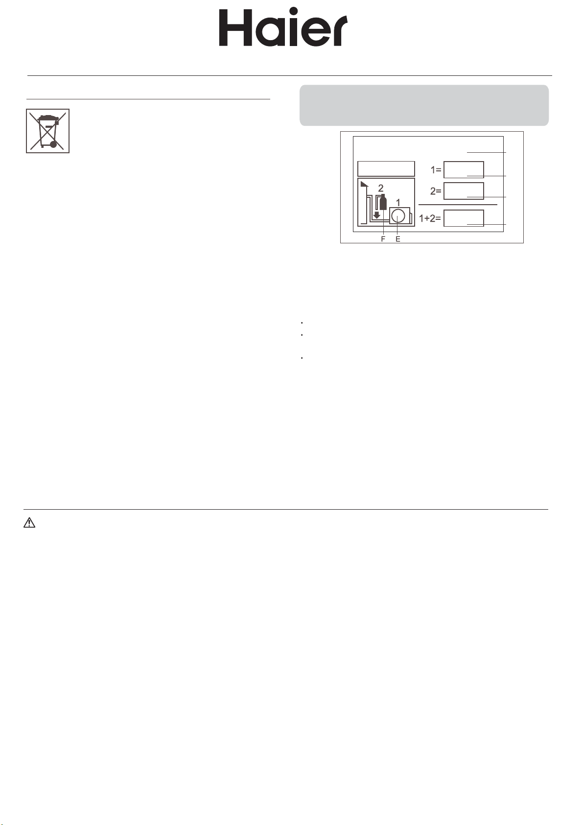
IMPORTANT INFORMATION REGARDING THE REFRIGERANT USED
Contains fluorinated greenhouse gases
covered by the Kyoto Protocol
R410A
This product contains fluorinated greenhouse gases covered
by the Kyoto Protocol.Do not vent into the atmosphere.
Refrigerant type:R410A
GWP*value:1975
GWP=global warming potential
Please fill in with indelible ink,
1 the factory refrigerant charge of the product
2 the additional refrigerant amount charged in the field
and
1+2 the total refrigerant charge
on the refrigerant charge label supplied with the product.
The filled out label must be adhered in the proximity of the
product charging port(e.g.onto the inside of the stop value
cover).
A contains fluorinated greenhouse gases covered by the
Kyoto Protocol
B factory refrigerant charge of the product:see unit name
plate
C additional refrigerant amount charged in the field
D total refrigerant charge
E outdoor unit
F refrigerant cylinder and manifold for charging
kg
kg
kg
A
B
C
D
WARNING
f the supply cord is damaged, it must be replaced by the manufacturer, its service agent or similarly qualified persons in
I
order to avoid a hazard.
This appliance is not intended for use by persons (including children) with reduced physical, sensory or mental capabilities,
or lack of experience and knowledge, unless they have been given supervision or instruction concerning use of the appliance
by a person responsible for their safety.
Children should be supervised to ensure that they do not play with the appliance.
This appliance can be used by children aged from 8 years and above and persons with reduced physical, sensory or
mental capabilities or lack of experience and knowledge if they have been given supervision or instruction concerning use
of the appliance in a safe way and understand the hazards involved. Children shall not play with the appliance. Cleaning
and user maintenance shall not be made by children without supervision.
The appliances are not intended to be operated by means of an external timer or separate remote-control system.
Keep the appliance and its cord out of reach of children less than 8 years.
The A-weighted sound pressure level is below 70 dB.
This appliance is intended to be used by expert or trained users in shops, in light industry and on farms, or for commercial
use by lay persons
The power cable should be H05RN-F 3G 4.0mm
2
.
Air conditioner working temperature: cooling 10~46 degree, heating -15~24 degree.
Page 3

1. Definitions
1.1. Meaning of warnings and symbols
Warnings in this manual are classified according to their
severity and probability of occurrence.
DANGER
Service company:
Qualified company which can perform or coordinate the
required serice to the unit.
Applicable legislation:
All international, European, national and local directives,
laws, regulations and/or codes which are relevant and
applicable for a certain product or domain.
Indicates an imminently hazardous situation which, if not
avoided, will result in death or serious injury.
WARNING
Indicates a potentially hazardous situation which, if not
avoided, could result in death or serious injury.
CAUTION
Indicates a potentially hazardous situation which, if not
avoided, may result in minor or moderate injury. It may
also be used to alert against unsafe practices.
NOTICE
Indicates situations that may result in equipment or
property-damage accidents only.
INFORMATION
This symbol identifies useful tiops or additional information.
Some types of danger are represented by special symbols:
Accessories:
Equipment which is delivered with the unit and which needs
to be installed according to instructions in the documentation.
Optional equipment:
Equipment which can ooptionally be combined to the products
as per the subject of this manual.
Field supply:
Equipment which needs to be installed according to
instructions in this manual, but which are not supplied by
Haier.
2. Safety considerations
The precautions here, all cover very impertant topics, so be
sure to follow them catefully.
All activities described in this manual shall be carried out by
an installer.
Electric current.
Danger of burning and scalding.
1.2. Meaning of used terms
Installation manual:
Instruction manual specified for a certain product or application,
explaining how to install, configure and maintain it.
Operation manual:
Instruction manual specified for a certain product or application,
explaining how to operate it .
Maintenance instructions:
Instruction manual specified for a certain product or application,
which explains ( if relevant ) how to install, configute, operate
and/or maintain the product or application.
Dealer:
Sales distributor for products as per the subject of this manual.
Installer
Technical skilled person who is qualified to install products
as per the subject of this manual.
User:
Person who is owner of the product and/or operates the
product.
Be sure to wear adequate personal protection equipment (
Protection gloves, safety glasses......) when performing
installation, maintenance or service to the unit.
If not sure of installation procedures or operation of the unit,
always contact your local dealer for advice and information.
Improper installation or attachment of equipment or
accessories could result in electric shock, short-circuit, leaks,
fire or other damage to the equipment. Be sure only to use
accessories, optional equipment and spare parts made by
which are specially designed for use with the products as
of subject in this manual and have them installed by an
installer.
DANGER: ELECTRICAL SHOCK
Switch off all power supply before removing the switch
box service panel or before making any connections
or touching electrical parts.
avoid electric shock, be sure to disconnect the power
To
supply 2 minute or more before servicing the electrical
parts. Even after 2 minute, always measure the voltage
at the terminals of main circuit capacitors or electrical
parts. Even after 2 minute, always measure the votage
at the terminals of main circuit capacitors or electrical
parts, and before touching, be sure that those voltages
are 50V DC or less.
3
Page 4

When service panels are removed, live parts can easily
be touched by accident, Never leave the unit unattended
during installation or servicing when the service panel is
removed.
DANGER: DO NOT TOUCH PIPING AND INTERNAL
PARTS
Do not touch the refrigerant piping, water piping or internal
parts during and immediately after operation. The piping
and internal parts may be hot or cold depending on the
working condition of the unit.
Your hand may suffer burns or frostbite if you touch the
piping or internal parts. To avoid injury, give the piping
and internal parts time to return to normal temperature
or, if you must touch them, be sure to wear protective
gloves.
Warning:
Ask your dealer or qualified personnel to carry out
installation work. Do not install the machine by yourself.
Improper installation may result in water leakage, electric
shocks or fire.
Perform installation work in accordance with this installation
manual.
Improper installation may lead to water leakage, electric
shocks or fire.
The equipment is not intended for use in a potentially
explosive atmosphere.
For 1UH series units only.
For year
conditions, such as Electronic Data Processing rooms,
contacet yout dealer or see the engineering databook or
the service manual.
Consult your local dealer regarding what to do in case
of refrigerant leakage. When the unit is to be installed in
a small room, it is necessary to take proper measures so
that the amount of any leaked refrigerant does not exceed
the concentration limit in the event of a leakage. Otherwise,
this may lead to an accident due to oxygen depletion.
Be sure to use only the specified accessories and parts
for installation work.
Failure to use the specified parts may result in water
leakage, electric shocks, fire, or the unit falling.
Install the unit on a foundation that can withstand its
weight.
Insufficient strength may result in the fall of equipment
and causing injury.
Carry out the specified installation work in consideration
of strong winds, typhoons, or earthquakes.
Improper installation work may result in accidents due to
fall of equipment.
Make sure that all electrical work is carried out by qualified
personnel according to the applicable legislation and this
installation manual, using a separate circuit.
Insufficient capacity of the power supply circuit or improper
electrical capacity of the power supply circuit or improper
electrical construction may lead to electric shocks or fire.
round cooling applications with low indoor humidity
Make sure that all wiring is secure, using the specified
wires and ensuring that external forces do not act on the
terminal connections or wires.
Incomplete connection or fixing may cause a fire.
When wiring between the indoor and outdoor units, and
wiring the power supply, form the wires so that the
fronstside panel can be securely fastened.
If the frontside panel is not in place, overheating of the
terminals, electric shocks or a fire may be caused.
If refrigerant gas leaks during installation work, ventilate
the area immediately.
Toxic gas may be produced if refrigerant gas comes into
contactwith fire.
After completing the installation work, check to make
sure that there is no leakage of refrigerant gas.
Toxic gas may be produced if refrigerant gas leaks into
the room and comes into contact with a source of fire,
such as a fan heater, stove or cooker.
When planning to relocate former installed units, you
must first recover the refrigerant after the pump down
operation.
Never directly touch any accidental leaking refrigerant.
This could result in severe wounds caused by frostbite.
Be sure to install an earth leakage circuit breaker in
accordance with applicable legislation. Failure to do so
may cause electrical shock and fire.
Caution:
Earth the unit.
Earthing resistance should be according to applicable
legislation.
Do not connect the earth wire to gas or water pipes,
lightning conductor or telephone earth wire.
Incomplete earthing may cause electric shocks.
Gas pipe.
Lgnition or explosion may occur if the gas leaks.
Water pipe.
Hard vinyl tubes are not effective earths.
Lightning conductor or telephone earth wire.
Electric potential may rise abnormally if struck by a
lightning bolt.
Install drain piping according to this installation manual
to ensure good drainage, and insulate the pipe to prevent
condensation.
Improper drain piping may cause water leakage, and
make the fumitures get wet.
Install the indoor and outdoor units, power wire and
connecting wire at least 1 meter away from televisions
or radios to prevent image interference or noise.
(Depending on the radio waves, a distance of 1 meter
may not be sufficient to eliminate the noise.)
Do not rinse the outdoor unit, This may cause electric
shocks or fire.
Do not install the unit in places such as the following:
Where there is mist of mineral oil, oil spray or vapour
for example a kitchen.
Plastic parts may deteriorate, and cause them to fall
out or water to leak.
Where corrosive gas, such as sulphurous acid gas,
is produced.
Corrosion of copper pipes or soldered parts may cause
the refrigerant to leak.
4
Page 5

Where there is machinery which emits electromagnetic
waves.
Electromagnetic
andcause malfunction of the equipment.
Where flammable gases may leak, where carbon fiber
or ignitable dust is suspended in the air or where volatile
flammables, such as thinner or gasoline, are handled.
SUch gases may cause a fire.
Where the air contains high levels of salt such as that
near the ocean.
Where voltage fluctuates a lot, such as in factories.
In vehicles or vessels.
Where acidic or alkaline vapour is present.
Do not allow a child to mount on the outdoor unit or
avoid placing any object on the unit. Falling or tumbling
may result in injury.
The unit may stop for several minutes during normal
operation for "defrosting the unit", or when in "thermostat
stop" operation.
This appliance is intended to be used by expert or trained
users in shops, in light industry and on farms, or for
commercial use by lay persons.
Provide a logbook
In accordance with the relevant national and international
codes, it may be necessary to provide a logbook with the
equipment containing at least
- info on maintenance.
- repair work,
- results of tests,
- stand-by periods,
- etc...
In Europe, EN378 provides the necessary guidance for this
logbook.
waves
may disturb the control system,
3. Before installation
3.1. Scope of this manual
This manual describes the procedures for handling, installing
and connecting 1UH071~140 units.
Check the following if the ground-fault circuit interrupter is
triggered:
Make sure that the interrupter is compatible with high
frequencies.
This unit has an inverter, so an interrupter capable of
handling high frequencies is needed to prevent
malfunction of the interrupter itself.
3.3. Precautions for R410A
The refrigerant requires strict cautions for keeping the
system clean, dry and tight.
- Clean and dry
Foreign materials (including mineral oils or moisture)
should be prevented from getting mixed into the system.
- Tight
Read "9. Precautions on refrigerant piping" on page 10
carefully and follow these procedures correctly.
Since
R410A is a mixed refrigerant, the required additional
refrigerant must be charged in its liquid state.(If the
refrigerant is in state of gas, its composition changes
and the system will not work properly).
The connected
exclusively for R410A.
indoor units must be indoor units designed
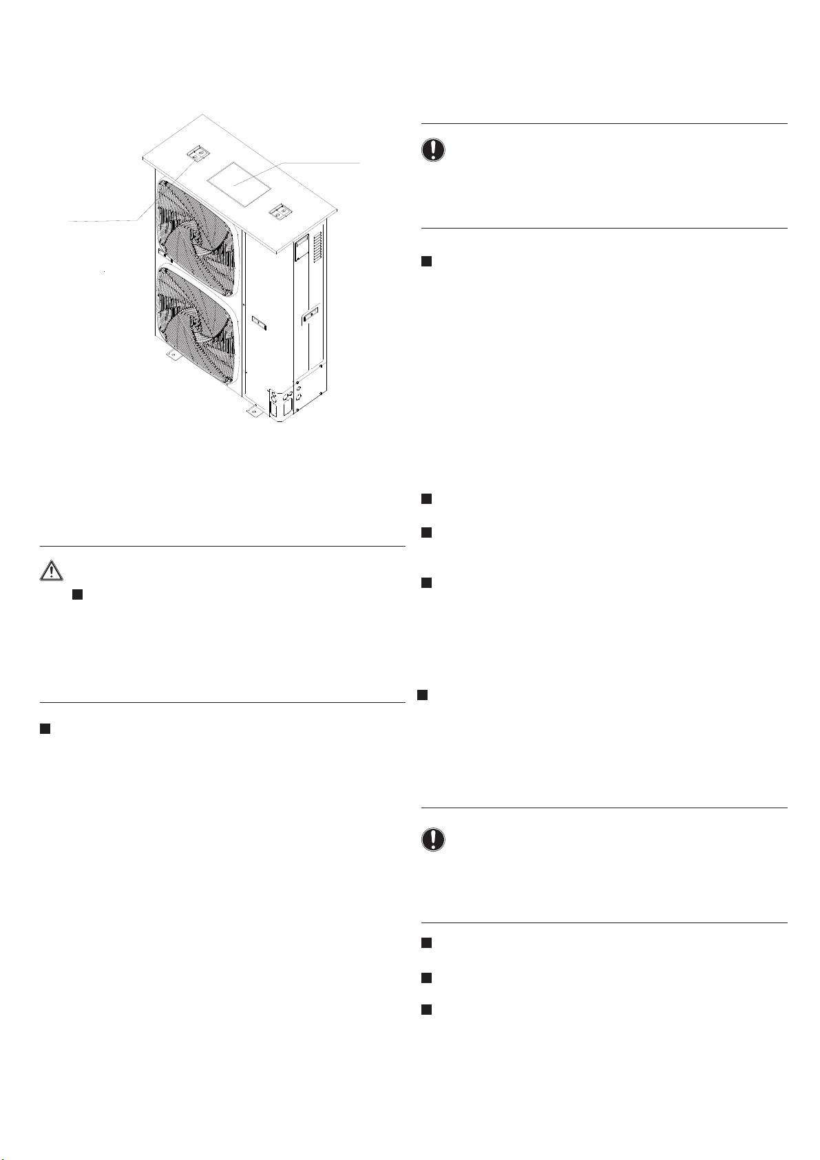
3.4. Installation
For installation of the indoor unit(s), refer to the indoor
unit installation manual.
Illustrations show 1UH140P1ERK outdoor unit type.
Other types also follow this installation manual.
This outdoor
when used as the outdoor unit for the simultaneous
operation system. Refer to catalogues for details.
Never operate the unit with a damaged or disconnected
discharge thermistor and suction thermistor, burning of
the compressor may occur.
Be sure to confirm the model name and the serial no.
of the outer(front) plates when attaching/detaching the
plates to avoid mistakes.
When closing the service panels, take care that the
tigntening torque does not exceed 4.1 N.M.
unit requires the pipe branching kit(optional)
3.2. Precautions
CAUTION
Since maximum working pressure is 4.15 MPa or 41.5
pipes of larger wall thickness may be required. Refer
bar,
to paragraph "6.2. Selection of piping material" on page
10.
NOTICE: Insulation resistance of the compressor
If, after installation, refrigerant accumulates in the
compressor, the insulation resistance can drop, but if it
is at least 1
Turn the power on and leave it on for six hours. Then,
check if the insulation resistance of the comressor has
risen or not.
The compressor will heat up and evaporate any refrigerant
in the compressor.
, then the machine will not break down.
5
Page 6
3.5. Accessories
Check if the following accessories are included with the unit:
See the figure below for the location of the accessories.
- Do not climb, sit or stand on top of the unit.
- Be sure that sufficient precautions are taken, in
accordance with applicable legislation, in case of
refrigerant leakage.
installation
manual
rubber base
foot
4. Selecting installation site
4.1. General
WARNING
Be sure to provide for adequate measures in order
to prevent that the outdoor unit be used as a shelter
bye small animals.
Small animals making contact with electrical parts
can cause malfunctions, smoke or fire. Please instruct
the customer to keep the area around the unit clean.
NOTICE
This is a class A product. In a domestic environment
this product may cause radio interference in which case
the user may be required to take adequate measures.
When installing the unit in a place exposed to strong
wind, pay special attention to the following.
Strong winds of 5 m/sec or more blowing against the
outdoor unit's air outlet causes short circuit (suction of
discharge air), and this may have the following
consequences:
- Deterioration of the operational capacity.
- Frequent frost acceleration in heating operation.
- Disruption of operation due to rise of high pressure.
- When a strong wind blows continuously on the face
of the unit, the fan can start rotating very fast until it
breaks.
Refer to the figures for installation of this unit in a place
where the wind direction can be foreseen.
Repare a water drainage channel around the foundation,
to drain waste water from around the unit.
If the water drainage of the unit is not easy, please build
up the unit on a foundation of concrete blocks, etc.(the
height of the foundation should be maximum 150mm).
If you install the unit on a frame, please install a waterproof
plate(field supplu) within 150mm of the underside of the
unit in order to prevent the invasion of water from the
lower direction.
When installing the unitin a place frequently exposed to
snow, pay special attention to elevate the foundation as
high as possible.
Make sure that the unit is installed level.
Select an installation site where the following conditions
are satisfied and that meets with your customer's approval.
- Places which are well-ventilated.
- Pllaces where the unit does not bother next-door
neighbours.
- Safe places which can withstand the unit's weight and
vibration and where the unit can be installed level.
- Places where there is no possibility of flammable gas
or product leak.
- The equipment is not intended for use in a potentially
explosive atmosphere.
- Places where servicing space can be well ensured.
- Places where the indoor and outdoor units's piping and
wiring lengths come within the allowable ranges.
- Places where water leaking from the unit cannot cause
damage to the location (e.g. in case of a blocked drain
pipe)
- Places where the rain can be avoided as much as
possible.
- Do not install the unit in places often used as work place.
In case of construction works (d.g.grinding works ) where
a lot of dust is created, the unit must be covered.
- Do not place any objects or equipment on top of the
unit( top plate).
4.2. General
NOTICE
When operating the outdoor unit in a low outdoor
amnient temperature, be sure to follow the instructions
described below.
To prevent exposure to wind, install the outdoor unit with
its suction side facing the wall.
Never install the outdoor unit at a site where the suction
side may be exposed directly to wind.
To prevent exposure to wind, install a baffle plate on the
air discharge side of the outdoor unit.
In heavy snowfall areas it is very important to select an
installation site where the snow will not affect the unit
and set the outlet side at a right angle to the direction
of the wind.
6
Page 7
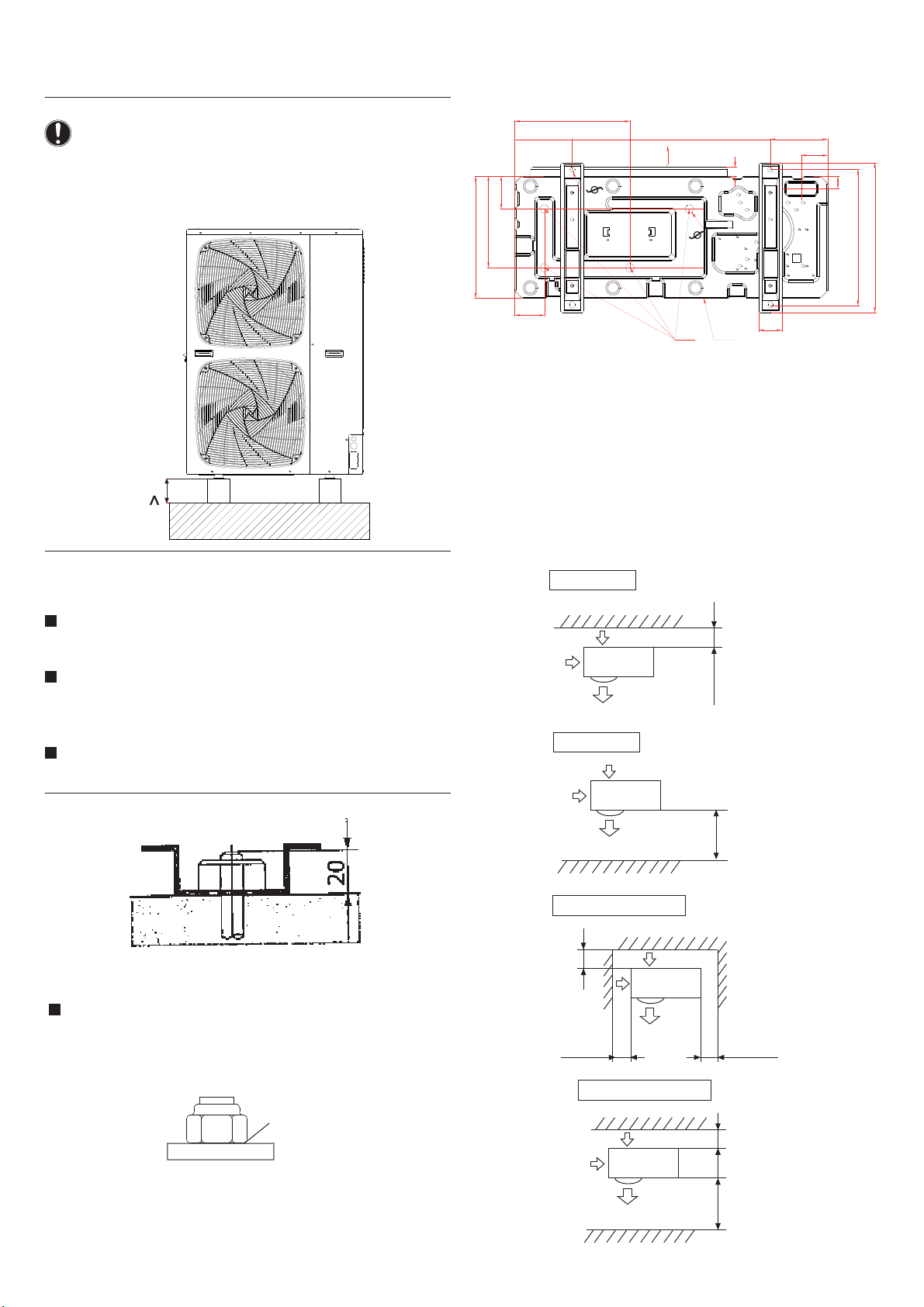
5. Precautions on installation
NOTICE
If drain holes of the outdoor unit are covered by a
mounting base or by floor surface, raise the unit in order
to provide a free space of more than 130mm under the
outdoor unit.
130mm
If the coating on the fastening area is stripped off, the
nuts rust easily.
Dimensions (bottom view)(unit of measurement:mm)
349
174 A 600 174
80
F
99
2-
15
C
27
4-
367
276
26
90
D
70
E
A leg pitch1
B leg pitch2
C Front grill (air outlet side)
D Drain hole
E Bottom frame
F Knock-out hole (for piping line)
37
450
B (405~410)
5.1. Foundation work
Check the strength and level of the installation ground
so that the unit will not cause any operating vibration or
noise after installation.
In accordance with the foundation drawing in the figure,
fix the unit securely by means of the foundation bolts.
(Prepare four sets of M12 foundation bolts, nuts and
washers each which are available on the market.)
It is best to screw in the foundation bolts until their length
are 20mm from the foundation surface.
5.2.Selection of installation location of outdoor
(1)Single-unit installation (unit: mm)
Back
Above 150
Front
Above 500
Back and side
Height of barriers is
below that of outdoor unit
Fix the outdoor unit to the foundation bolts using nuts
with resin washers(1) as shown in the figure.
1
Above 200
Above 150 Above 300
Front and back
Above 150
Above 1000
7
Page 8
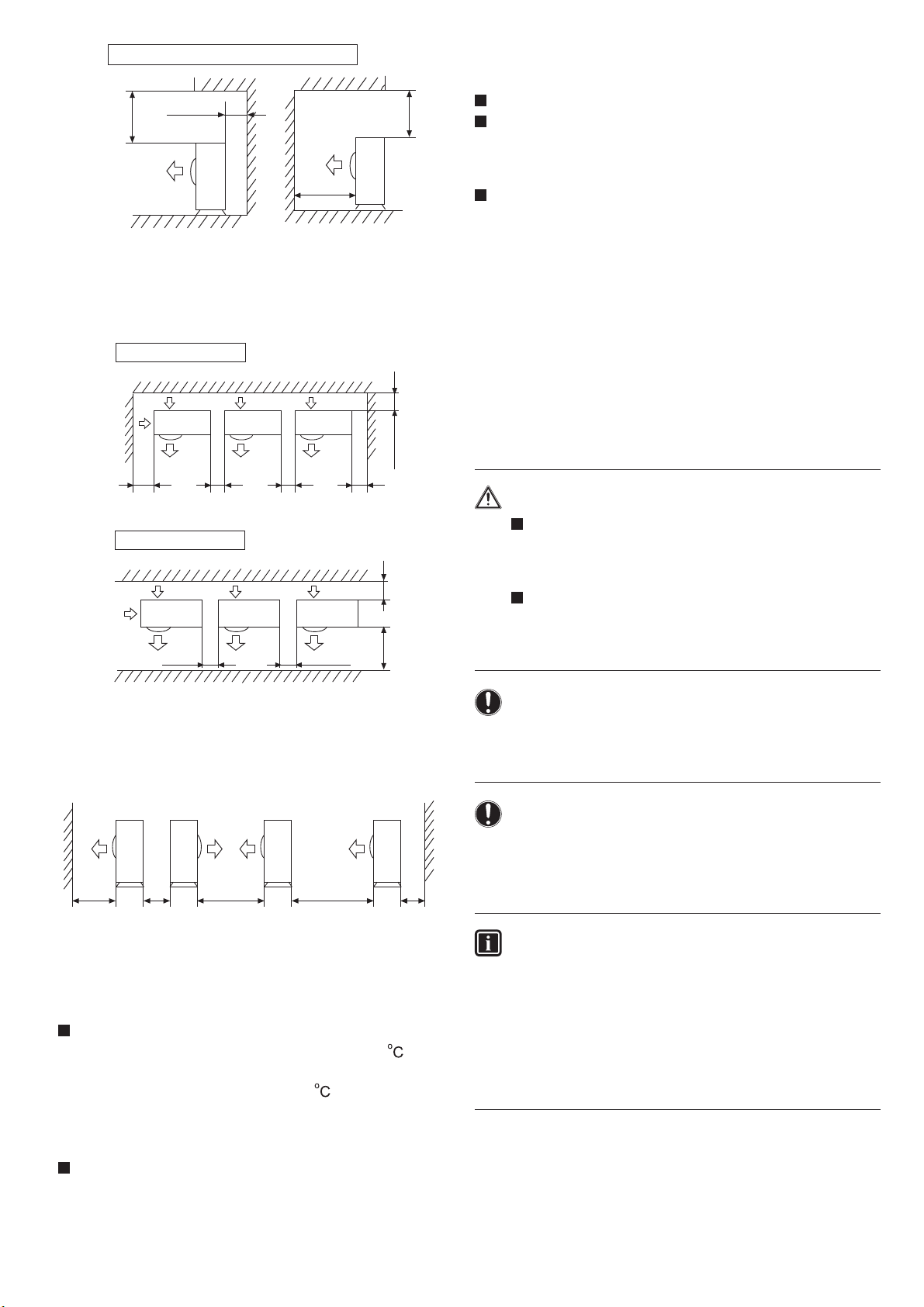
When barriers exist above the unit
5.3. Drain pipe disposal
Above 150
Above 500
Above
1000
The top and two side surfaces must be exposed to open
space, and barriers on at least one side of the front and back
shall be lower than the outdoor unit.
(2) Multi-unit installation (unit: mm)
Back and side
Above 200
Above 150
Above 300
Above 300
Above 300
Front and back
Make sure the drain works properly.
where buildups of snow can be expected, the
Above 1000
In regions
accumulation and freezing of snow in the space between
the heat exchanger and external plate may lower operating
efficiency.
After punching the knock-out hole, the application of
repair-type paint on the surface around the edge sections
is recommended to prevent rust.
6. Refrigerant pipe size and
allowable pipe length
DANGER
Piping an other pressure containing parts shall
comply with the applicable legislation and shall be
suitable for refrigerant. Use phosphoric acide
deoxidised seamless copper for refrigerant.
Installation shall be done by an installer, the choice
of materials and installation shall comply with
applicable legislation. In Europe the EN378 is the
application standard that shall be used.
Above 300 Above 300
Above 1000 Above 200
Height of barriers is below that of outdoor unit
(3) Multi-unit installation in front and back (unit: mm)
Standard
Above 1000
Above 300
Above 1500
Above 2000
Above 200
The top and two side surfaces must be exposed to open
space, and barriers on at least one side of the front and back
shall be lower than the outdoor unit.
The installation service spaces shown in the illustrations
are based
on an air intake temperature of 35
(DB) for
COOL operation. In regions where the air intake
temperature regularly exceeds 35
(DB), or if the heat
load of outdoor units is expected to regularly exceed
the maximum operating capacity, reserve a larger space
than that indicated at the air intake side of units.
Regarding the required air outlet space, position the
units with consideration to the space required for the
onsite refrigerant piping work as well. Consult your dealer
if the work conditions do not match those in the drawings.
INFORMATION
It is forbidden to discharge refrigerant into the atmosphere.
Collect the refrigerant in accordance with the freon
collection and destruction law.
NOTICE
To persons in charge of piping work:
Be sure to open the stop valve after piping installing
and vacuuming is complete. (Running the system with
the valve closed may break the compressor.)
NOTICE
Do not use flux when brazing the refrigerant piping.
For brazing, use phosphor copper brazing filler metal
(BCuP) which does not require a flux.
(If a chlorine flux is used, the piping will corrode, and
if the flux contains fluoride, if will cause the coolant oil
to deteriorate, adversely affecting the coolant piping
system.)
8
Page 9

6.1. Necessary Tools and Materials
Prepare the following tools and materials necessary for installing and servicing the unit.
Necessary tools for use with R410A(Adaptability of tools that are for use with R22 and R407C).
1. To be used exclusively with R410A ( Not to be used if used with R22 or R407C )
Tools/Materials Use Notes
Gauge Manifold Evacuating,refrigerant charging 5.09MPa on the High-pressure side.
Charging Hose Evacuating, refrigerant charging Hose diameter larger than the concentional ones.
Refrigerant Recovery Equipment Refrigerant recovery
Refrigerant Cylinder Refrigerant charging Write down the refrigerant type. Pink in color at the top of the cylinder.
Refrigerant Cylinder Charging Port Refrigerant charging Hose diameter larger than the conventional ones.
Flare Nut Connecting the unit to piping Use Type-2 Flare nuts.
2. Tools and materials that may be used with R410 with some restrictions
Tools/Materials Use Notes
Gas leak detector Detection of gas leaks The ones for HFC type refrigerant may be used.
Vacuum Pump Vacuum drying May be used if a reverse flow check adaptor is attached.
Flare Tool Flare machining of piping Chages have been made in the flare machining dimension.Refer to the next page.
Refrigerant Recovery Equipment Recovery of refrigerant May be used if designed for use with R410A.
3. Tools and materials that are used with R22 or R407C that can also be used with R410A
Tools/Materials Use Notes
Vacuum Pump with a Check Valve Vacuum drying
Bender Bending pipes
Torque Wrench Tightening flare nuts Only 12.70 (1/2'') and 15.88(5/8'') have a larger flare machining dimension.
Pipe Cutter Cutting pipes
Welder and Nitrogen Cylinder Welding pipes
Refrigerant Charging Meter Refrigerant charging
Vacuum Gauze Checking vacuum degree
4. Tool and materials that must not used with R410A
Tools/Materials Use Notes
Charging Cylinder Refrigerant Charging Must not be used with R410-type units.
Tools for R410A must be handled with special care, and keep moisture and dust from entering the cycle.
9
Page 10

6.2. Piping Materials
Types of Copper Pipes (Reference)
Maximum Operation Pressure Applicable Refrigerants
3.4MPa R22, R407C
4.15MPa R410A
Use pipes that meet the local standards.
Piping Materials/Radial Thickness
Use pipes made of phosphorus deoxidized copper.
Since the operation pressure of the units that use R410A is higher than that of the units for use with R22, use pipes with
at least the radial thickness specified in the chart below. (Pipes with a radial thickness of 0.7mm or less may not be used.)
Size(mm) Radial Thickness(mm)Size(inch)
6.35
9.52
12.7
15.88
19.05 3/4'' 1.0t
1/4''
3/8''
1/2''
5/8''
0.8t
0.8t
0.8t
1.0t
Although it was possible to use type-O for pipes with a size of up to
1/2H pipes for units that use R410A.(Type-O pipes may be used if the pipe size is
Type
Type-O pipes
Type-1/2H or Hpipes
19.05(3/4") with conventional refrigerants, use type-
19.05 and the radial thickness is 1.2t.)
The table shows the standards in Japan. Using this table as a reference, choose pipes that meet the local standards.
Flare Machining (type-O and OL only)
The flare machining dimensions for units that use R410A is larger than those for units that use R22 in order to increase
air tightness.
Flare Machining Dimension(mm)
External dimension of pipes
6.35
9.52
12.7
15.88
19.05
Size
1/4"
3/8"
1/2"
5/8"
3/4"
Dimension A
R410A R22
9.1
13.2
16.6
19.7
24.0
9.0
13.0
16.2
19.4
23.3
Dimension A
If a clutch type flare tool is used to machine flares on units that use R410A, make the protruding part of the pipe between
1.0 and 1.5mm. Copper pipe gauge for adjusting the length of pipe protrusion is useful.
Flare Nut
Type-2 flare nuts instead of type-1 nuts are used to increase the strength. The size of some of the flare nuts have also
been changed.
Flare nut dimension(mm)
17.0
22.0
26.0
29.0
36.0
Dimension B
17.0
22.0
24.0
27.0
36.0
Dimension B
External dimension of pipes Size
6.35
9.52
12.7
15.88
19.05
1/4"
3/8"
1/2"
5/8"
3/4"
R410A(Type2) R22(Type1)
Using this table as a reference, choose pipes that meet the local standards.
10
Page 11

NOTICE
For new installations, use the standard pipe sizes.
When using existiong pipes, size-up is allowed as
mentioned in the table above.
Additional restrictions towards allowable pipe lengths,
as mentioned in the table 7.3 on page 11, must be
taken into account.
Not using the standard lpipe size may result in
capacity decrease. The installer must acknowledge
this and judge this very carefully in function of the
complete installation.
Existing or pre-installed piping can be used
Cautions on handling the service port
Always use a charge hose equipped with a valve
depressor pin, since the service port is a Schrader type
valve.
After handling the service port, make sure to tighten the
service port cap securely. For the tightening torque, refer
to the table below.
Check for refrigerant leaks after tightening the service
port cap.
7. Refrigerant piping
1. Piping must comply with the criteria below.
Piping diameter must comply with the limitations as
indicated in paragraph "7.2. Refrigerant pipe size " on
page 11.
Piping length must be withinlimits of the allowable piping
length as in paragraph "7.3. Allowable pipe length and
height difference" on page 11.
Piping must be designed for R410A. See paragraph
"6.2. Selection of piping material" on page 10.
2. Piping can be reused without cleaning when:
Total 1-way piping length:
No compressor breakdown has occurred in the history
50m.
of the unit to be replaced.
A correct pump down operation can be executed:
- Operate the unit continuously for 30minutes in cooling
mode.
- Execute a pump down operation.
- Remove the air conditioning units to be replaced.
Check the contamination inside the existing piping.
If you cannot meet all these requirements, the existing
pipes must be cleaned or replaced after removing the air
conditioning units to be replaced.
7.1. Piping diagram for single split
Flare connection
Indoor
unit
Gas pipe
Liquid
pipe
7.2. Piping size for single split
ABH071H1ERG
ABH090H1ERG
ABH105H1ERG
ABH125K1ERG
ABH140K1ERG
PipeModel
Liquid pipe
Gas pipe
Diameter of pipe
9.52mm
15.88mm
Install the removed flare nuts
90+0.5
to the pipes to be connected,
then flare the pipes.
3-way stop valve
Outdoor
unit
3-way stop valve
3. Prepare the flare connections for higher pressure. See
paragraph 6.2
Cautions on handling the stem cap
The stem cap is sealed where indicated by the arrow.
ake care not to damage it.
T
After handling the stop valve, make sure tighten the stem
cap securely
. For the tightening torque, refer to the table
below.
Check for refrigerant leaks after tightening the stem cap.
7.3. Limitations for one way piping length and vertical
height difference for single split
Model
One way piping
length
ABH071H1ERG
ABH090H1ERG
ABH105H1ERG
less than 50 m
ABH125K1ERG
ABH140K1ERG
less than 75 m
Vertical height
difference
(between indoor
less than 30 m
less than 30 m
and outdoor)
11
Page 12

Precautions for refrigerant piping
Do not twist or crush piping.
Be sure that no dust is mixed in piping.
Bend piping with as wide angle as possible.
Keep insulating both gas and liquid piping.
Check flare-connected area for gas leakage.
7.4. Piping connection method
Apply refrigerant oil to the joint and the flange.
To bend a pipe, give the roundness as possible not to
crush the pipe.
When connecting pipe, hold the pipe centre to centre and
then screw nut on by hand, refer to Fig.
Be careful not to let foreign matters, such as sands enter
the pipe.
Spanner
Joint
Spanner
Nut
Pipe diameter Fastening torque (N.m)
Liquid pipe 6.35mm
Liquid pipe 9.52mm
Gas pipe 12.7mm
Gas pipe 15.88mm
Gas pipe 19.05mm
14.2-17.2
32.7-39.9
49.5-60.3
61.8-75.4
97.2-118.6
Cutting out the two slits makes it possible to install as
shown in the figure "Field pipes in 4 directions".
(Use a metal saw to cut out the slits.)
To install the connecting pipe to the unit in a downward
direction, make a knock-out hole by penetrating the
centre area around the knock-out hole using a
6mm
drill (4x).
After knocking out the knock-out hole, it is recommended
to apply repair paint to the edge and the surrounding
end surfaces to prevent rusting.
When passing electrical wiring through the knock-out
holes, remove any burrs from the know-out holes and
wrap the wiring with protective tape to prevent damage.
7.5. Preventing foreign objects from entering
Plug the pipe through-holes with putty or insulating
material (procured locally) to stop up all gaps, as shown
in the figure.
Field pipes can be installed in four directions (A, B, C,
D, E).
E
C
A
B
D
A: Forward
B: Backward
C: Sideways
D: Downward
E: Power supply cable,outdoor and indoor connection cable
1 Putty or insulating material (produced locally)
If there is any possibility that small animals enter the system
through the knock-out holes, plug the holes with packing
materials (field supplied).
Insects or samall animals entering the outdoor unit may cause
a short circuit in teh electrical box.
Seal knock-out holes to avoid snow and humidity entering.
7.6. Preventing foreign objects from entering
Be careful not to let the indoor and outdoor piping come
into contact with the compressor terminal cover.
If the liquid-side piping insulation might come into contact
with it, adjust the height as shown in the figure below.
Also, make sure the field piping does not touch the bolts
or outer panels of the compressor.
When the outdoor unit is installed above the indoor unit
the following can occur:
The condensed water on the stop valve can move to the
indoor unit. To avoid this, please cover the stop valve with
sealing material.
12
Page 13

If the temperature is higher than 30
higher than RH 80
should be at least 20mm in ouder to avoid condensation
on the surface of the sealing.
Be sure to insulate the liquid and gas-side field piping.
NOTICE
Any exposed piping may cause condensation.
, then thickness of the sealing materials
and the humidity is
NOTICE
Do not purge the air with refrigerants. Use a vacuum
pump to evacuate the installation. No additional
refrigerant is provided for air purging.
Make sure that the gas stop valve and liquid stop
valve are firmly closed before performing the leak
test or vacuum drying.
8.2. Leak test
(The highest temperature that the gas-side piping can
reach is around 120
material which is very resistant.)
DANGER
No not touch piping and internal parts.
7.7. Cautions for necessity of a trap
To avoid the the risk of oil held inside the riser piping flowing
back into the compressor when stopped and causing liquid
compression phenomenon, or cases of deterioration of oil
return, it will be necessary to provide a trap at each difference
in height of 10m in the riser gas piping.
A trap is not necessary when the outdoor unit is installed
at higher position than the indoor unit.
, so be sure to use insulating
8. Leak test and vacuum
drying
When all piping work is complete and the outdoor unit is
connected to the indoor unit, it is necessary to :
The leak test must satisfy specification EN378-2.
1 Vacuum leak test
1.1 Evacuate the system from the liquid and gas piping
to -100.7 kPa(5 Torr).
1.2 Once reached, turn off the vacuum pump and check
that the pressure does not rise for at least 1 minute.
1.3 Should the pressure rise, the system may either
contain moisture (refer to the paragraph " Vacuum
drying ") or have leaks.
2 Pressure leak test
2.1 Break the vacuum by pressurizing with nitrogen gas
to a minimum gauge pressure of 0.2 MPa (2 bar).
Never set the gauge pressure higher than the
maximum operation pressure of the unit, i.e. 4.0MPa
(40bar).
2.2 Test for leaks by applying a bubble test solution to
all piping connections.
NOTICE
Make sure to use a recommended bubble test solution
from your wholesaler.
Do not use soap water, which may cause cracking of
falre nuts (soap water may contain salt, which absorbs
moisture that will freeze when the piping gets cold).
and/or lead to corrosion of flared joints (soap water may
contain ammonia which causes a corrosive effect between
the brass flare nut and the copper flare).
check for any leakages in the refrigerant piping
to perform vacuum drying to remove all moisture in the
refrigerant piping.
If there is a possibility of moisture being present in the
refrigerant piping (for example, rainwater may have entered
the piping), first carry out the vacuum drying procedure
below until all moisture has been removed.
8.1. General guidelines
All piping inside the unit has been factory tested for leaks.
Use a 2-stage vacuum pump with a non-return valve
which can evacuate to a gauge pressure of-100.7kPa(5
Torr absolute,-755mm Hg).
Connect the vacuum pump to both the service port of
the gas stop valve and the liquid stop valve to increase
efficiency.
8.3. Vacuum drying
To remove all mositure from the system, proceed as follows:
1 Evacuate the system for at least 2 hours to a target
vacuum of -100.7 kPa(=-1.007 bar).
2 Check that, with the vacuum pump turned off, the target
vacuum is maintained for at least 1 hour.
3 Should you fail to reach the target vacuum within 2 hours
or maintain the vacuum for 1 hour, the system may contain
too much moisture.
4 In that case, break the vacuum by pressurizing with
nigrogen gas to a gauge pressure of 0.05 MPa (0.5bar)
and repeat steps 1 to 3 unit all moisture has been removed.
5 The stop valves can now be opened, and/or additional
refrigerant can be charged .
13
Page 14

INFORMATION
After opening the stop valve, it is possible that the
pressure in the refrigerant piping does not rise. This
migeh be caused by e.g. the closed state of the
expansion valve in the outdoor unit circuit, but does not
present any problem for correct operation of the unit.
This unit requires additional charging of refrigerant
according to the length of refrigerant piping connected
at the site.
Make sure to charge the refrigerant in liquid state to the
liquid pipe. Since R410A is a mixed refrigerant, its
composition changes if charged in its gaseous state and
normal system operation would then no longer be assured.
Before charging, check whether the refrigerant cylinder
has a suphon attached or not and position the cylinder
accordingly.
9. Charging refrigerant
9.1. Important information regarding the
refrigerant used
This product contains fluorinated greenhouse gases covered
by the Kyoto Protocol. Do not vent gases into the
atmopsphere.
9.2. Precautions and general guidelines
When servicing the unit requires the refrigerant system
to be opened, treatment and evacuation of refrigerant
must be done in accordance with applicable legislation.
Refrigerant can not be charged until field wiring has been
completed.
Refrigerant may only be charged after performing the
leak test and vacuum drying.
CAUTION
Fill using a cylinder
with a siphon
attached Charge the
liquid refrigerant with
the cylinder in upright
position.
On this model it is not necessary to charge additionally if
the piping length
20m.
Fill using a cylinder
siphon attached
with a
Charge the liquid
refrigerant with the
cylinder in up-sidedown position.
9.3. Complete recharging
NOTICE
Berore recharging, make sure to execute vacuum
drying of the intermal piping of the unit as well. To do
so, use the internal service port of the unit. Do not use
the service ports located on the stop valve, since
vacuum drying can not be performed properly from
these ports.
Outdoor units have 1 port on the piping. It is between
the heat exchanger and the 4-way valve.
When charging a system, care shall be taken that
its maximum permissible charge is never exceeded,
in view of the danger of liquid hammer.
WARNING
Refrigerant cylinders shall be opened shlowly.
Always use protective gloves and protect your eyes
when charging refrigerant.
DANGER
When the power is on, please close the front panel
when leaving the unit unattended.
Charging with an unsuitable substance may cause
explosions and accidents, so always ensuren that
the appropriate refrigerant (R410A) is charged.
In case complete recharging is required (after a leak, etc.),
refer to teh information below to determine the necessary
amount of refrigerant.
WARNING
Some sections of the refrigerant circuit may be
isolated from other sections caused by components
with specific functions (e.g. valves). The refrigerant
circuit therefore features additional service ports for
vacuuming, pressure relief or pressurizing the circuit.
In case it is required to perform brazing on the unit,
ensure that there is no ressure remaining inside the
unit. Internal pressures need to be released with ALL
the service ports indicated on the figures below
opened. The location is depending on mode type.
14
Page 15

-
-
-
-
1 Make sure that stop valves
both on liquid and on gas side
are open.
_
9.4. Total charging weight of the refrigerant
(after a leak, etc.)
The total charging amounts relate to the refrigerant piping
length as in "Maximum total one-way piping length" of the
table in paragraph "8.4. Allowable pipe length and height
difference" on page 8.(E.g. twin: L1+L2)/
2 Push the BS4 pumping-down
operation button on the PC
board of the outdoor unit (8
seconds).
Compressor and outdoor
fan will start operation
automatically.
The indoor unit fan may
automatically start running.
Please pay attention to
this.
3 Close the stop valve on the
liquid side securely about 2
minutes after the compressor
started ooperation.
Never leave the outdoor
unit unattended with
oopened front panel when
power supply is on.
In case the stop valve on
the liquid side is not
securely closed during
4 Once compressor operation
stops after 2 to 5 minutes (a),
close the stop valve on the
gas side securely.
compressor operation,
during compressor
operation, pumping-down
operation cannot be
executed.
5 Turn off the power supply.
(a) If after finishing pumping-down operation the outdoor
unit does not operate, not even when the remote controller
switch is turned on, the remote controller may or may
not indicate "
". But this is not a malfunction.
Refrigerant piping length (liquid side)
Model
(a)
1UH071N1ERG
1UH090N1ERG
1UH105NS1ERG
1UH125P1ERG
1UH125P1ERK
1UH140P1ERG
1UH140P1ERK
5-10m
10-20m
2.5 2.5 2.5
2.5 2.5 2.5
30-40m
20-30m
2.95
2.95
3.4
3.4 3.85
3.7 3.7 3.7 4.15 4.6
40-50m
5.05 5.5 5.95
50-60m
---
-
60-70m
670-80m
-
-
10. Pump down operation
This unit is equipped with an automatic pump down operation
which will collect all refrigerant from the field piping and indoor
unit in the outdoor unit. To protect the environment, make sure
to perform the following pump down operation when relocating
or disposing of the unit.
INFORMATION
For more details, refer to the applicable service manual.
When in need of operation, turn off the main power supply
and turn it on again. Make sure that stop valves both on
liquid and gas side are open and be sure to ooperate the
unit in cooling operation during test run.
WARNING
Make sure to re-open both stop valves before restarting
operation of the unit.
11. Electrical wiring work
WARNING
All wiring must be performed by an authorized
electrician.
All components procured on the side and all elecrtic
construction shall comply with the applicable
legislation.
DANGER: HIGH VOLTAGE
To avoid electrical shock, make sure to disconnect the
power supply 1 minute or more before servicing the
electrical parts. Even after 1 minute, always measure
the voltage at the terminals of main circuit capacitors
or electrical parts and, before touching , make sure that
those voltages are 50VDC or less.
15
Page 16
NOTICE
To persons in charge of electrical wiring work:
Do not oerate the unit until the refrigerant piping is
complete. (Running it before the piping is ready will
break the compressor.)
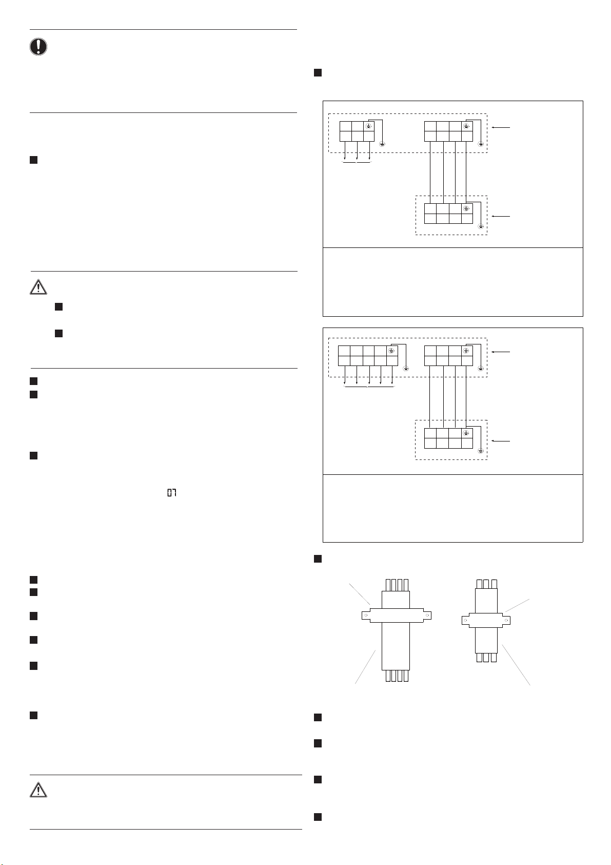
11.2. Connecting power supply and inter-unit
wiring
Connect and fix the power supply cable, indoor-outdoor
connection cable as following:
11.1. Precautions on electrical wiring work
When servicing the unit requires the refrigerant system
to be opened, treatment and evacuation of refrigerant
must be done in accordance with applicable legislation.
Refrigerant can not be charged until field wiring has been
completed.
Refrigerant may only be charged after performing the
leak test and vacuum drying.
DANGER
Before obtaining access to terminal devices, all
supply circuits must be interrupted.
Be sure to install an earth leakage circuit breaker
in accordance with aplicable legislation. Failure to
do so may cause electrical shock.
Use only copper wires.
A main switch or other means for disconnection, having
a contact separation in all poles, must be incorporated
in the fixed wiring in accordance with applicable legislation.
Do not turn on the main switch until all the wiring is
completed.
For Y1
Make sure to connect power supply cables in normal
phase. If
of the indoor unit indicates "
operate. Change any two of the three power supply
cables (L1,L2,L3) to correct phase.
If the contact in the magnetic switch should be forcibly
turned on while the equipment is inoperative, the
compressor will burn out. Never try to forcibly turn on
the contact.
Never squeeze bundled cables into a unit.
Fix cables so that cables do not make contact with the
pipes (especially on high pressure side).
Secure the electrical wiring with cable ties as shown in
the figure in 11.2 (for single split) or 12.3 (for maxi split).
Make sure no external pressure is applied to the terminal
connectors.
When installing the earth leakage circuit breaker make
sure that it is compatible with the inverter (resistant to
high frequency electrical noise ) to avoid unnecessary
opening of the earth leakage circuit breaker.
As
advancing capacitor not only will deteriorate power factor
improvement effect, but also may cause capacitor
abnormal heating accident due to high-frequency waves.
Therefore, never install a phase advancing capacitor.
CAUTION
Be sure to install the required fuses or circuit
breakers.
connected in reverse phase, the remote controller
" and the equipment cannot
this unit is equipped with an inverter, installing a phase
LN
123
Outdoor unit
terminal blocks
Power supply:
1PH,220-240V~,
50/60Hz
123
Indoor unit
terminal blocks
For single phase power supply models:
1UH071N1ERG,1UH090N1ERG,1UH105N1ERG,
1UH125P1ERG,1UH140P1ERG
Power supply cable: H05RN-F 3G 4.0mm
2
Indoor and outdoor connection cable: H05RN-F 4G 2.5mm
RST N
123
Outdoor unit
terminal blocks
Power supply:
380-415V,3N~,
50/60Hz
123
Indoor unit
terminal blocks
For three phase power supply models:
1UH125P1ERK,1UH140P1ERK
Power supply cable: H05RN-F 5G 2.5mm
Indoor and outdoor connection cable:
H05RN-F 4G 2.5mm
2
2
Fix the cable with the clip to prevent slide.
Clip
Outdoor-indoor unit
Power supply cable
connection cable
Secure the cable to the stop valve attachment plate so
that it does not slide.
When cables are routed from the unit, a protection sleeve
for the conduits (PG-insertions) can be inserted at the
knock-out hole.
When you do not use a wire conduit, be sure to protect
the wires with vinyl tubes to revent the edge of the knockout hole from cutting the wires.
Follow the electric wiring diagram for electrical wiring
works.
16
2
Clip
Page 17

Form the wires and fix the cover fimmly so that the cover
may be fit in properly.
When you do not use a wire conduit, be sure to protect
the wires with vinyl tubes to revent the edge of the knockout hole from cutting the wires.
Follow the electric wiring diagram for electrical wiring
works.
Form the wires and fix the cover fimmly so that the cover
may be fit in properly.
- Do not connect wires of different gauge to the same
power supply terminal. (Looseness in the connection may
cause overheating.)
Use the correct screwdriver to tighten the terminal screws.
Small screwdrivers can damage the screw head and
prevent appropriate tightening.
Over-tightening the terminal screws can damage the
screws.
11.3. Specifications of standard wiring
components
CAUTION
Select all cables and wire sizes in accordance with
applicable legislation.
After finishing the electrical work, confirm that each
electric part and terminal inside the electric part box
is connected securely.
The earth leakage breaker must be a high-speed
type breaker of 30 mA(
0.1 s).
12.1. Pre-run checks
Items to check
Electrical wiring
Inter-unit wiring
Ground wire
Refrigerant
piping
Extra refrigerant
Is the wiring as mentioned on the
wiring diagram?
Make sure no wiring has been
forgotten and that there are no missing
phases or reverse phases.
Is the unit properly grounded?
Is the wiring between units connected
in series correct?
Are any of the wiring attachment
screws loose?
Is the insulation resistance at leaset
1
- Use a 500V mege-tester when
measuring insulation.
- Do not use a mega-tester for low voltage circuits.
Is the size of the piping appropriate?
Is the insulation material for the piping
attached securely?
Are both the liquid and gas pipes
insulated?
Are the stop valves for both the liquid
side and the gas side open?
Did you write down the extra
refrigerant and the refrigerant piping
length?
?
12. Test operation
DANGER
Never leave the unit unattended during installation
or servicing. When the service panel is removed
live parts can be easily touched by accident.
INFORMATION
Note that during the first running period of the unit,
required power input may be higher than stated on the
nameplate of the unit. This phenomenon originates
from the compressor that needs elapse of a 50 hours
run in period before reaching smooth operation and
stable power consumption.
Be sure to perform a test run.
Be sure to fully open the liquid-side and gas-side stop
valves. If you operate the unit with stop valves closed, the
compressor will break down.
Be sure to execute the first test run of the installation in
cooling mode operation.
Never leave the unit unattended with an open front panel
during test run.
12.2. Precautions regarding test-runs
1
In order to detect stop valves failing to open, operation
of the unit is compulsorily performed in cooling for 2-3
minutes during the first test run, even if the remote
controller was set to heating operation. In this case, the
remote controller will have kept displaying the heating
symbol all the time and the unit will switch to heating
operation automatically after elapse of that time.
In case you cannot ooperate the unit in test run mode
2
for any unusual reason, refer to "12.6. Failure diagnosis
at the moment of first installation" on page 22.
In case of a wireless remote controller, execute the run
3
only after having installed the indoor unit decoration
panel with infrared receiver first.
In case the panels of indoor units are not yet installed
4
to the indoor units, make sure to shut off the power
supply after finishing the complete test run.
complete test run surely includes shutting off power
A
5
after having performed a normal operation stop on the
remote controller. Do not stop operation by turning circuit
breakers off.
17
Page 18

12.3. Refrigerant pipe size for maix split system
The MAXI SPLIT system is an ideal option for open spaces in medium sized premises such as shops and offices,where
two,three or four units are required.These can be Cassettes ( AB Series) or Ceiling supended (AC Series) models and
can be connected to a single outdoor unit using twin,triple,quadruple manifold.Please refer to the table below to choose
suitable manifold and wire controller according to combinations of indoor unit and outdoor unit.
The matching table of MAXI SPLIT series
Manifold
Model
FQG-2Y100A 2
FQG-2Y200A 2
FQG-3Y100A 3
FQG-3Y200A 3
FQG-4Y200A 4
Gas side manifold Liquid side manifold
Outdoor
unit Model
1UH105 18000BTU
1UH125
1UH140
1UH105 12000BTU
1UH125
1UH140
1UH125
1UH140
Indoor Unit
Model
24000BTU
28000BTU
18000BTU
12000BTU
Number
of indoor
Units
Wire
controler
YR-E14 OR
YR-E16
YR-E14 OR
YR-E16
YR-E14 OR
YR-E16
YR-E14 OR
YR-E16
YR-E14 OR
YR-E16
MAXI SPLIT SYSTEM UNITS WIRING DIGRAM
123
123
123
123
123
terminal block
Indoor unit 1
terminal block
Indoor unit 2
terminal block
Indoor unit 3
terminal block
Indoor unit 4
SRNTNL
3N~,50Hz,
380-400V
3PH TYPE
master
slave
slave
slave
1PH~,50Hz,
220-230V
1PH TYPE
Note:
1. The master is the indoor unit which connect to a wired
controller, others are slaves, please purchase wired
controller separately for MAXI system.
2. For one MAXI split system there is only one master.
3. For the MAXI system with 2 to 3 indoor units, the wiring
method is the same with the diagram on the left except for
the indor units quantity.
4. Make sure that the wire connection for all units in MAXI
system OK before running.
terminal block
Outdoor unit
18
Page 19

12.4. Specification of refrigerant charge for single split and maxi split.
1.It is not neccesary to charge additionally when the piping length L+P
20m.
2.Please charge refrigerant additionally according to the following table when the piping length L+P
complete recharge .
Single Split Twin Triple Quadruple
L1
L2
L
L3
(L-20)*45+P*30
(L-20)*45+P*30
(L-20)*45+P*30
L>20
L
20,L+P>20
__
(L+P-20)*30
(L+P-20)*30
P=L1+L2+L3+L4
Charge(g)
1UH105
1UH125
1UH140
P(m)
L
L>20
(L-20)*45
(L-20)*45
(L-20)*45
P=0
L
,L+
L 20
(L+P-20)*30
(L+P-20)*45
(L+P-20)*45
P>20
P=L1+L2 P=L1+L2+L3
L1
L2
L>20
(L-20)*45+P*30
(L+P-20)*45
(L+P-20)*45
L
20,L+P>20
( +P-20)*30L
(L+P-20)*30
(L+P-20)*30
Remark:
a.L is the main pipe length of liquid pipe;P is the sum length of branch liquid pipes.
b.The piping length L+P means the sum of the main pipe and branch pipes.
For MAXI system (Twin,Triple,Quadruple), piping length=L+P
L.
For single split system,L+P=L,because P=0.
Example 1:
Outdoor unit
1UH105
Note:
(1)L=15<20;L+P=L+L1+L2=15+10+5=30>20
(2)Refrigerant charging amount=(L+P-20)*30=300g
(3)TYPE 18K means capacity 18000Btu/h type
L=15( 9.52)
L1=10( 6.35)
L2=5( 6.35)
Indoor unit
TYPE 18K
TYPE 18K
Example 2:
Outdoor unit
1UH125
Note:
(1)L=30>20;P=L1+L2+L3+L4=10+10+5+5=30
(2)Refrigerant charging amount=(L-20)*45+P*30=1350g
(3)TYPE 12K means capacity 12000Btu/h type
L=30( 9.52)
L1=10( 6.35)
L1=10( 6.35)
L1=5( 6.35)
L1=5( 6.35)
20m or need to
L1
L2
L
L3
L4
L>20
__
(L-20)*45+P*30
(L-20)*45+P*30
Indoor unit
TYPE 12K
TYPE 12K
TYPE 12K
TYPE 12K
19
Page 20

When installing MAXI SPLIT Series(1UH105N1ERG/1UH125P1ERG/1UH125P1ERK/1UH140P1ERG/1UH140P1ERK),Please
refer to the table below concerning the pipe lengths , heights and sizes.
608080
608080
80 80
20
Page 21
12.5 Before Installing (Relocating) the Unit or Performing Electric Work
CAUTION
Ground the unit.
Do not connect the grounding on the unit to gas pipes,water
pipes, lightning rods, or the grounding terminals of
telephones. Improper grounding presents a risk of electric
shock, smoke, fire, or the noise caused by improper
grounding may cause the unit to malfunction.
Make sure the wires are not subject to tension.
If the wires are too taut, they may break or generate
heat and/or smoke and cause fire.
Install a breaker for current leakage at the power source
to avoid the risk of electric shock.
Without a breaker for current leakage, there is a risk
of electric shock, smoke or fire.
Use breakers and fuses (electrical current breaker, remote
switch<switch+Type-B fuse>,molded case circuit breaker)
with a proper current capacity.
The use of large-capacity fuses, steel wire, or copper
wire may damage the unit or cause smoke or fire.
Before the Test Run
Do not spray water on the air conditioners or immerse the
air conditioners in water.
Water on the unit presents a risk of electric shock.
Periodically check the platform on which is placed for damage
to prevent the unit from falling.
If the unit is left on a damaged plarform, it may topple
over, causing injury.
When installing draining pipes, follow the instructions in the
manual, and make sure that they properly drain water so as
to avoid dew condensation.
If not installed properly, they may cause water leaks
and damage the furnishings.
Properly dispose of the packing materials.
Things such as nails may be included in the package.
Dispose of them properly to prevent injury.
Plastic bags present a choking hazard to children.
Tear up the plastic bags before disposing of them to
prevent accidents.
CAUTION
Do not operate switches with wet hands to avoid electric.
Do not touch the refrigerant pipes with bare hands during
and immediately after operation.
Depending on the state of the refrigerant in the system,
certain parts of the unit such as the pipes and
compressor may become very cold or hot and may
subject the person to frost bites or burning.
Do not operated the unit without panels and safety guards
in their proper places.
They are there to keep the users from injury from
accidentally touching rotating, high-tempreture or
high-voltage parts.
Do not turn off the power immediately after stopping the unit.
Allow for at least five minutes before turning off the unit,
otherwise the unit may leak water or experience other
problems.
Do not operate the unit without air filters.
Dust particles in the air may clog the system and cause
malfunction.
21
Page 22
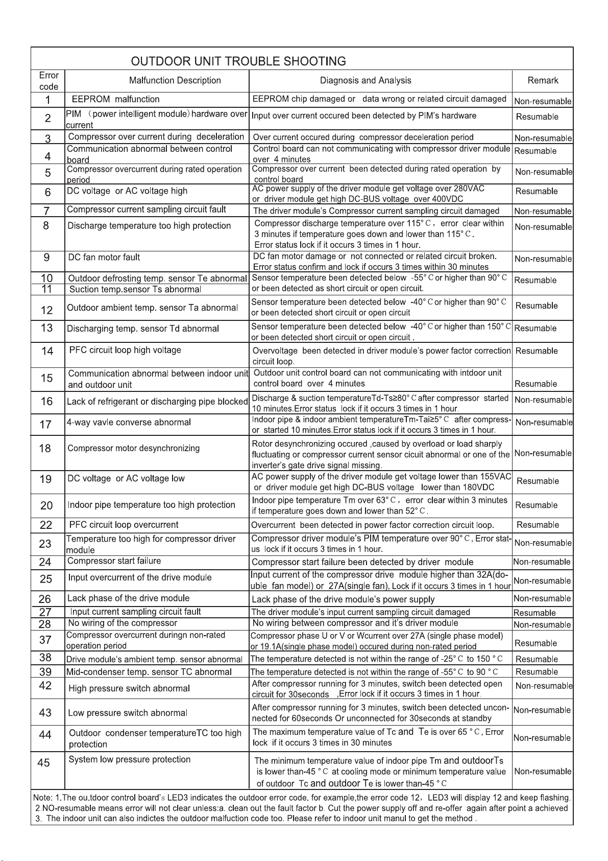
12.6. Failure diagnosis
22
Page 23

Page 24

Address:Haier Industrial Park,Qianwangang Road,Eco-Tech Development Zone,Qingdao 266555,Shandong,P.R.C.
Contacts: TEL +86-532-88936943; FAX +86-532-8893-6999
Website: www.haier.com
 Loading...