

Haier 1U25S2SQ1FA, 1U71S2SR1FA, 1U25BEFFRA, 1U35BEFFRA, 1U35S2SQ1FA Installation Manual
...Page 1
ROOM AIR CONDITIONER
INSTALLATION MANUAL
0010589581
1U25S2SQ1FA
1U35S2SQ1FA
1U50S2SR1FA
1U71S2SR1FA
1U25BEFFRA
1U35BEFFRA
1U50JEFFRA
1U68REFFRA
1U25S2PJ1FA
1U35S2PJ1FA
Please read this manual carefully before installtion.
This appliance is filled with R32.
Keep this operation manual for future reference.
Manufactured: Qingdao Haier Air Conditoner General Co, Ltd.
Ɋɭɫɫɤɢɣ
Nederlands
Page 2

Page 3

Contents
Loading and Unloading/Transporting Management/Storage Requirements.............................3
Installation Instructions.............................................................................................................3
Relocation Procedures.............................................................................................................7
Maintenance Instructions..........................................................................................................7
Scrapping and Recovery..........................................................................................................10
Indoor/Outdoor Unit Installion Drawings............... ............................................... .................... 12
Safety Precautions ...................................................................................................................13
Read Before Installation ....................................... ....................................................................17
Installation Procedure........................................... ....................................................................20
Outdoor Unit Troubleshooting.............................................................................. .....................25
Warning .................................................................................................................................1
Page 4
WARNING:
Use a cable of suitable length,Do not use tapped wires or an extension lead as this may cause
overheating, electric shocks, fire or explosion.
All the cables shall have got the European authentication certificate. During installation, when the
connecting cables break off, it must be assured that the grouding wire is the last one to be broken off.
If refrigerant gas leaks during installation, ventilate the area immediately.oxic gas may be produced
After completing installation, check for refrigerant gas leakage
When installing or relocating the air conditioner, be sure to bleed the refrigerant circuit to ensure
it is free of air, and use only the specified refrigerant (R32).
Make sure ground connection is correct and reliable.Do not earth the unit to a utility pipe, lightning
conductor or telephone earth lead. Imperfect earthing may result in electric shocks.
Be sure to install an earth leakage circuit explosion-proof breaker.
Do not use means to accelerate the defrosting process or to clean, other than those recommended by
the manufacturer.
The breaker of the air conditioner should be all-pole switch and explosion-proof. The distance
between its two contacts should not be no less than 3mm. Such means for disconnection must be
incorporated in the wiring.
Read the precautions inthis m anual
carefully before operating the unit.
This appliance is filled with R32.
Ask your dealer or qualified personnel to carry out installation work.Do not attempt to install
the air conditioner yourself. Improper Installation may result in water leakage, electric shocks
, fire or explosion.
Keep this manual where the user can easily nd it.
Install the air conditioner in accordance with the instructions in this installation manual
Be sure to use only the specified accessories and parts for installation work.
Install the air conditioner on a foundation strong enough to withstand the weight of the unit.
Electrical work must be performed in accordance with relevant local and national regulations
and with instructions in this installation manual,Be sure to use a dedicated power supply circuit
only. The wiring method should be in line with the local wiring standard.The type of connecting
wire is H07RN-F.
.
The appliance must be stored in a room without continuously operating ignition sources, the radius of
the storage area should be no less than 2.5 m (for example:open flames, an operating gas appliance
or an operating electric heater).
Do not pierce or burn.
Be aware that refrigerants may not contain an odour.
Comply with national gas regulations.
This appliance can be used by children aged 8 years and above and persons with reduced
physical, sensory or mental capabilities or lack of experience and knowledge if they have
been given superivision or instruction concering use of the appliance in a safe way and
understand the hazards involved. Children shall not play with the appliance. Cleaning and
user maintenance shall not be made by children without supervision.
The air conditioner can not be discarded or scrapped Randomly
Reusable mechanical connectors and flared joints are not allowed indoor.
If you need please contact
customer service personnel of Haier to scrap in order to obtain the correct disposal methods.
gg g
if the refrigerant comes into contact with fire,and explosion may be happen.
The appliance must be installed, operated and stored in a room with a floor area larger than 3m
The room should be well ventilated.
1
Page 5
CE
All the products are in conformity with the following
European provision:
- Low Voltage Directive
2014/35/EU
-Electomagnetic CompatibilitY 2014/30/EU
ROHS
The products are fulfilled with the requirements in the
directive 2011/65/EU of the European parliament and of
council on the Restriction of the use of Certain Hazardous
Substances in Electrical and Electronic Equipment (EU
RoHS Directive)
WEEE
DISPOSAL REQUIREMENTS:
Your air conditioning product is marked with this
symbol.This means that electrical and electronic
products shall not be mixed with unsorted
household waste. Do not try to dismantle the
system yourself : the dismantling of the air
EUROPEAN REGULATIONS
CONFORMITY FOR THE MODELS
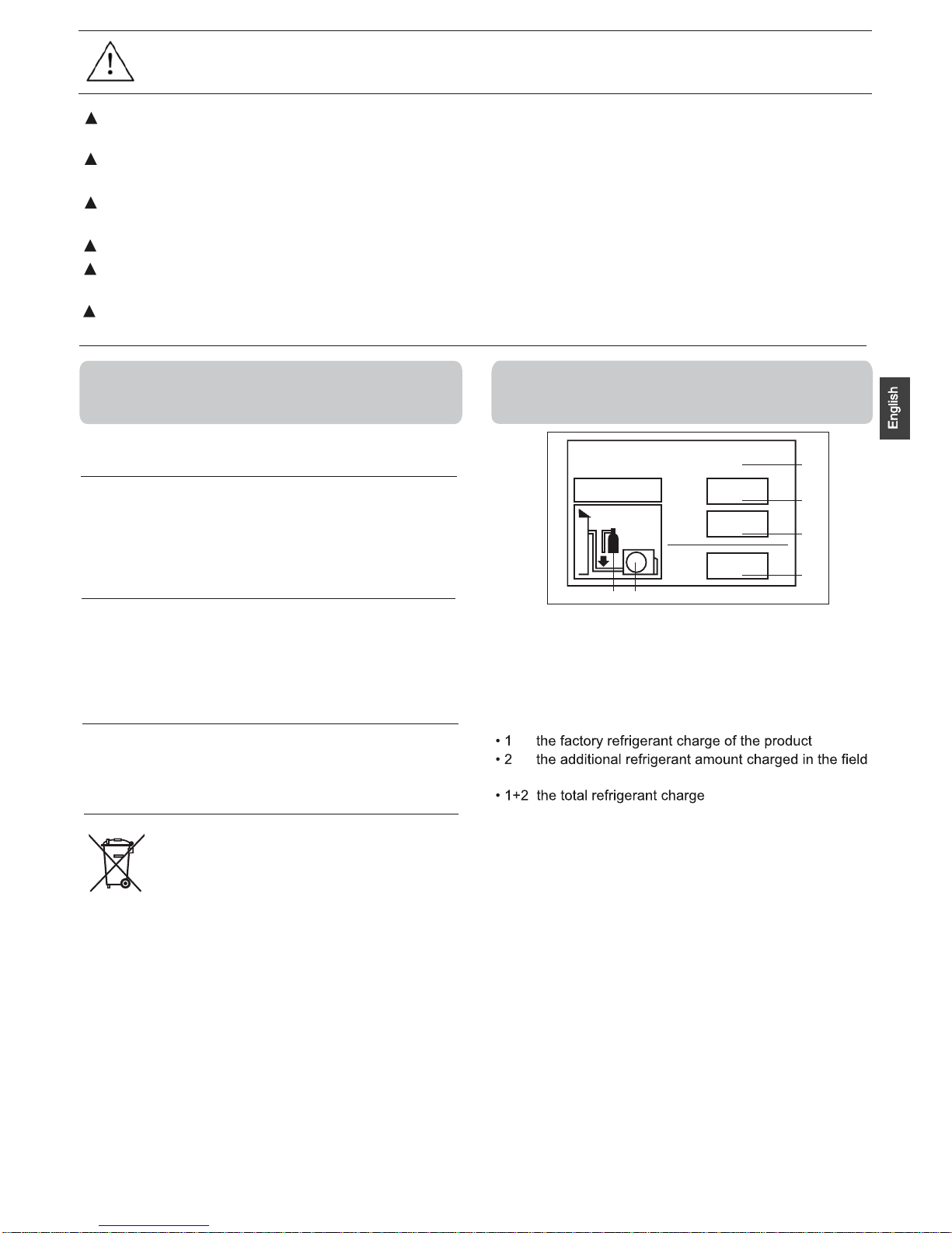
1
1+2=
kg
R32
2
kg
2=
1=
B
C
D
FE
kg
A
This product contains fluorinated greenhouse gases covered
by the Kyoto Protocol. Do not vent into the atmosphere.
Refrigerant type: R32
GWP=global warming potential
Please fill in with indelible ink,
and
on the refrigerant charge label supplied with the product.
The filled out label must be adhered in the proximity of the
product
charging port (e.g. onto the inside of the stop value
A contains fluorinated greenhouse gases covered by the
Kyoto
Protocol
B factory refrigerant charge of the product: see unit name
plate
C additional refrigerant amount charged in the field
D total refrigerant charge
E outdoor unit
F refrigerant cylinder and manifold for charging
IMPORTANT INFORMATION REGARDING THE REFRIGERANT USED
In accordance with the directive 2012/19/EU of the European
parliament, herewith we inform the consumer about the disposal requirements of the electrical and electronic products.
conditioning system,treatment of the refrigerant, of oil and of
other part must be done by a qualified installer in
accordance
with relevant local and national legislation. Air conditioners
must be treated at a specialized treatment facility for reuse,
recycling and recovery. By ensuring this product is disposed
of correctly, you will help to prevent potential negative consequences for the environment and humen health. Please
contact the installer or local authority for more information.
Battery must be removed from the remote controller and disposed of separately in accordance with relevant local and
nationl legislation.
Contains fluorinated greenhouse gases
covered by the Kyoto Protocol
cover).
Voltage:230V
Climate:T1
CAUTION:
Tighten the flare nut according to the specified method such as with a torque wrench.If the flare nut
is too tight, it may crack after prolonged use, causing refrigerant leakage.
Do not install the air conditioner at any place where there is danger of flammable gas leakage.
In the event of a gas leakage, build-up of gas near the air conditioner may cause a fire to break out.
Take adequate steps to prevent the outdoor unit being used as a shelter by small animals.Small animals
making contact with electrical parts can cause malfunctions, smoke or fire.
Please instruct the customer to keep the area around the unit clean
The temperature of refrigerant circuit will be high, please keep the inter-unit wire away from copper pipes
that not thermally insulated.
Only qualified personnel can handle, fill, purge and dispose of the refrigerant.
GWP* value=675
2
Page 6
Loading and Unloading/Transporting Management/Storage Requirements
Loading and Unloading Requirements
1) The products shall be carefully handled during loading and unloading.
2) Rude and barbarous handling such as kicking, throwing, dropping, bumping, pulling and rolling is not
allowed.
3) The workers engaged in loading and unloading must be subject to necessary trainings on the potential
hazards caused by barbarous handling.
4) Dry powder extinguishers or other suitable fire extinguishing apparatus within the period of validity shall be
equipped at the loading and unloading site.
5) The untrained personnel cannot be engaged in loading and unloading of flammable refrigerants air
conditioner.
6) Before loading and unloading, anti-static measures shall be taken, and phones cannot be answered during
loading and unloading.
7) Smoking and open fire are not allowed around the air conditioner.
Transporting Management Requirements
1) The maximum transporting volume of finished products shall be determined as per local regulations.
2) The vehicles used for transporting shall be operated as per local laws and regulations.
3) Dedicated after-sales vehicles shall be used for maintenance, and exposed transporting of refrigerant
cylinders and the products to be maintained is not allowed.
4) The rain cover or similar shielding material of transporting vehicles shall be provided with certain flame
retardancy.
5) Leakage warning device of flamma
ble refrigerant shall be installed inside the closed-type compartment.
6) Anti-static device shall be equipped inside the compartment of transporting vehicles.
7) Dry powder extinguishers or other suitable fire extinguishing apparatus within the period of validity shall be
equipped inside the driver's cab.
8) Orange-white or red-white reflective stripes shall be pasted on the sides and tail of the transporting vehicles,
to remind the vehicles behind of keeping distance.
9) The transporting vehicles shall run at a constant speed, and heavy acceleration/deceleration shall be avoided.
10) Combustibles or the static articles cannot be transported simultaneously.
11) High-temperature area shall be avoided during transporting, and necessary radiating measures shall be taken
in case the temperature inside the compartment is too high.
Storage Requirements
1) The storage package of equipment used shall be such that no leakage of refrigerant will be caused due to
mechanical damage of the equipment inside.
2) The maximum quantity of the equipment allowed to be stored together shall be determined as per local
regulations.
Installation Instructions
Installation Precautions
WARNING!
The area of the room in which R32 refrigerant air conditioner is installed cannot be less than the minimum
area specified in the table below, to avoid potential safety problems due to out-of-limit of refrigerant
concentration inside the room caused by leakage of refrigerant from refrigeration system of the indoor unit.
Once the horn mouth of connecting lines is fastened, it may not be used again (the air tightness may be
affected).
A whole connector wire shall be used for indoor/outdoor unit as required in the operation specification of
installation process and operation instructions.
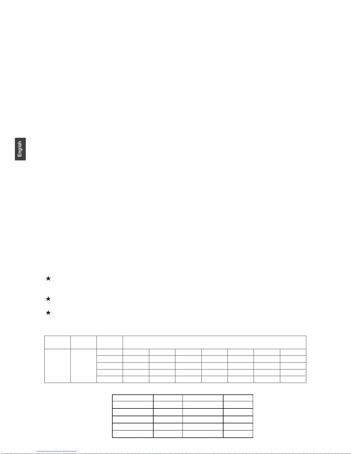
Minimum Room Area
Type
LFL
kg/m3
hv
Total Mass Charged/kg
Minimum Room Area/m
2
R32 0.306
1.224 1.836 2.448 3.672 4.896 6.12 7.956
0.6 29 51 116 206 321 543
1.0 10 19 42 74 116 196
1.8 3 6 13 23 36 60
2.2 2 4 9 15 24 40
m
3
The maximum refrigerant charge amount (M)
Mkg Mkg
1.0
1.1
1.45
0.9
0.92
1.35
1.6
0.95 0.95
1.6
1U25S2SQ1FA
1U35S2SQ1FA
1U50S2SR1FA
1U70S2SR1FA
1U25BEFFRA
1U35BEFFRA
1U50JEFFRA
1U68REFFRA
1U25S2PJ1FA
1U35S2PJ1FA
unit model
unit model
Page 7
Safety Awareness
1. Procedures: operation shall be made as per controlled procedures to minimize the probability of risks.
2. Area: area shall be divided and isolated appropriately, and operation in an enclosed space shall be avoided.
Before the refrigeration system is started or before hot working, ventilation or opening of the area shall be
guaranteed.
3. Site inspection: the refrigerant shall be checked.
4. Fire control: the fire extinguisher shall be placed nearby, and fire source or high temperature is not allowed;
the sign of “No smoking” shall be arranged.
Unpacking Inspection
1. Indoor unit: nitrogen is sealed during the delivery of indoor units (inside the evaporator), and the red sign at
the top of the green plastic seal cap on the evaporator air pipes of the indoor unit shall be checked first after
unpacking. In case the sign is raised, the nitrogen sealed still exists. Afterwards, the black plastic seal cap at the
joint of evaporator liquid pipes of the indoor unit shall be pressed, to check whether nitrogen still exists. In case
no nitrogen is sprayed out, the indoor unit is subject to leakage, and installation is not allowed.
2. Outdoor unit: the leak detection equipment shall be extended into the packing box of the outdoor unit, to
check whether the refrigerant is leaking. If the refrigerant leakage is identified, installation is not allowed, and the
outdoor unit shall be delivered to the maintenance department.
Inspection on Installation Environment
1. The room area checked cannot be less than the area specified on the warning sign of the indoor unit.
2. Inspection on the surrounding environment of place of installation: the outdoor unit of flammable
refrigerants air conditioner cannot be installed inside an enclosed room reserved.
3. Power supply, switches or other high-temperature articles such as the fire source and oil heater shall be
avoided below the indoor unit.
4. The power supply shall be provided with earthing wire and be reliably earthed.
5. While punching the wall with an electric drill, whether embedded water/electricity/gas pipelines are
designed at the hole preset by the user shall be verified in advance. It is recommended that the through-wall holes
reserved shall be used as much as possible.
Safety Principles of Installation
1. Favorable ventilation shall be maintained at the place of installation (doors and windows are opened).
2. Open fire or high-temperature heat source (including welding, smoking and oven) higher than 548
is not
allowed within the scope of flammable refrigerant.
3. Anti-static measures shall be taken, such as the wearing of cotton clothes and cotton gloves.
4. The place of installation shall be convenient for installation or maintenance, and cannot be adjacent to heat
source and flammable and combustible environment.
5. In case of refrigerant leakage of the indoor unit during installation, the valve of the outdoor unit shall be
closed immediately, and windows shall be opened, and all the personnel shall be evacuated. After the leakage of
refrigerant is handled, the indoor environment shall be subject to concentration detection. Further handling is not
allowed until the safety level is reached.
6. In case the product is damaged, it must be delivered to the maintenance point. Welding of refrigerant
pipelines at the user’s site is not allowed.
7. The installation position of air conditioner shall be convenient for installation or maintenance. Barriers shall
be avoided around the air inlet/outlet of the indoor/outdoor unit, and the electrical appliance, power switches,
sockets, valuables and high-temperature products within the scope of both sidelines of the indoor unit shall be
avoided.
4
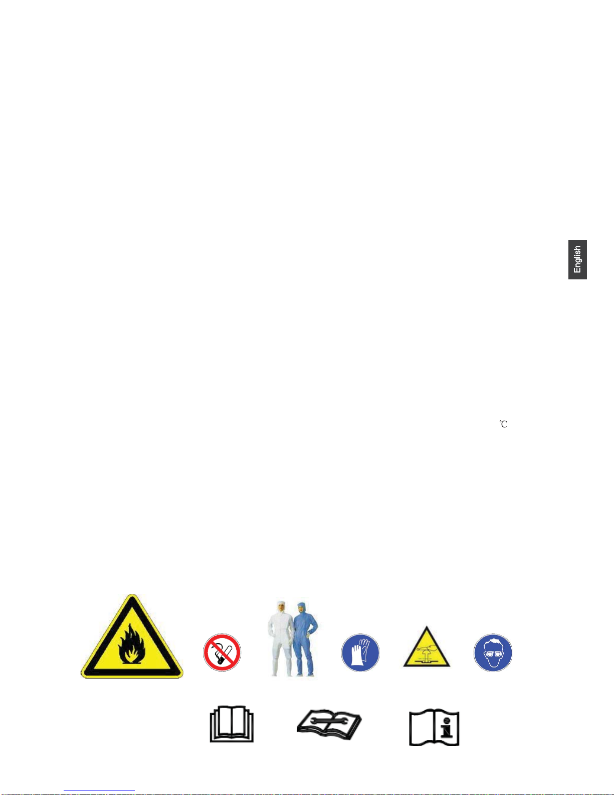
No fire source around the
place of installation
Read operator’ manual
Read technical manual
Operator’ manual;operating instructions
Cotton clothes Anti-static gloves
BEWARE
ELECTROSTATICS
Goggles
Page 8
• Electrical Safety Requirements
Note:
1. The surrounding conditions (ambient temperature, direct sunlight and rainwater) shall be noticed during
electrical wiring, with effective protective measures being taken.
2. Copper wire cable in line with local standards shall be used as the power line and connector wire.
3. Both the indoor unit and outdoor unit shall be reliably earthed.
4. Wiring for the outdoor unit shall be made first and then the indoor unit. The air conditioner can only be
powered on after wiring and pipe connection.
5. The dedicated branch circuit must be used, and leakage protector with sufficient capacity must be installed.
• Qualification Requirements of Installer
Relevant qualification certificate must be obtained as per national laws and regulations.
• Indoor Unit Installation
1. Fixation of wall panel and piping layout
In case of left/right water pipe connection for the indoor unit, or in case the evaporator interface of the indoor
unit and the horn mouth of the connecting piping cannot be extended to the outdoor side for installation, the
connector pipes shall be connected to the evaporator piping interface of the indoor unit in the process of horn
mouth.
2. Piping layout
During layout of connecting pipes, drain hose and connector wires, the drain hose and connecting wire shall
be placed at the bottom and top respectively. The power line cannot be twined with the connector wire. The drain
pipes (especially inside the room and machine) must be winded with thermal insulation materials.
3. Nitrogen charging for pressure maintaining and leak detection
After the evaporator of the indoor unit is connected to the connector pipe (after welding), nitrogen more than
4.0MPa shall be charged inside the evaporator and the piping connected to evaporator with a nitrogen cylinder
(adjusted by a reducing valve). Afterwards, the valve of the nitrogen cylinder shall be closed, for leak detection
with soapy water or leak detecting solution. The pressure shall be maintained for more than 5 minutes, and then
whether the system pressure is reduced or not shall be observed. In case the pressure is reduced, leakage can be
identified. After the leak point is handled, the steps above shall be repeated.
After the evaporator of the indoor unit is connected to connecting piping, nitrogen shall be charged for
pressure maintaining and leak detection. Afterwards, the evaporator shall be connected to the two-way stop valve
and three-way stop valve of the outdoor unit. After the copper cap of the connecting piping is fastened, nitrogen
more than 4.0MPa shall be charged at the access hole of the three-way stop valve with a charging hose. The valve
of the nitrogen cylinder shall be closed, for leak detection with soapy water or leak detecting solution. The
pressure shall be maintained for more than 5 minutes, and then whether the system pressure is reduced or not shall
be observed. In case the pressure is reduced, leakage can be identified. After the leak point is handled, the steps
above shall be repeated.
The operation above can also be completed after the indoor unit is connected to the connecting pipelines and
the two-way stop valve and three-way stop valve of the outdoor unit, after the access hole of the outdoor unit is
connected to the nitrogen cylinder and pressure gauge and after more than 4.0MPa nitrogen is charged. No leak
points are identified in the leak detection at the joint/welding junction of the indoor unit and at the joint of
connecting pipelines of the two-way stop valve and three-way stop valve of the outdoor unit. It must be
guaranteed that each joint is available for leak detection during inst all ation.
The next step (vacuumizing with a vacuum pump) can only be continued after the installation steps (nitrogen
charging for pressure maintaining and leak detection normal) are completed.
• Outdoor Unit Installation
1. Fixation and connection
Note:
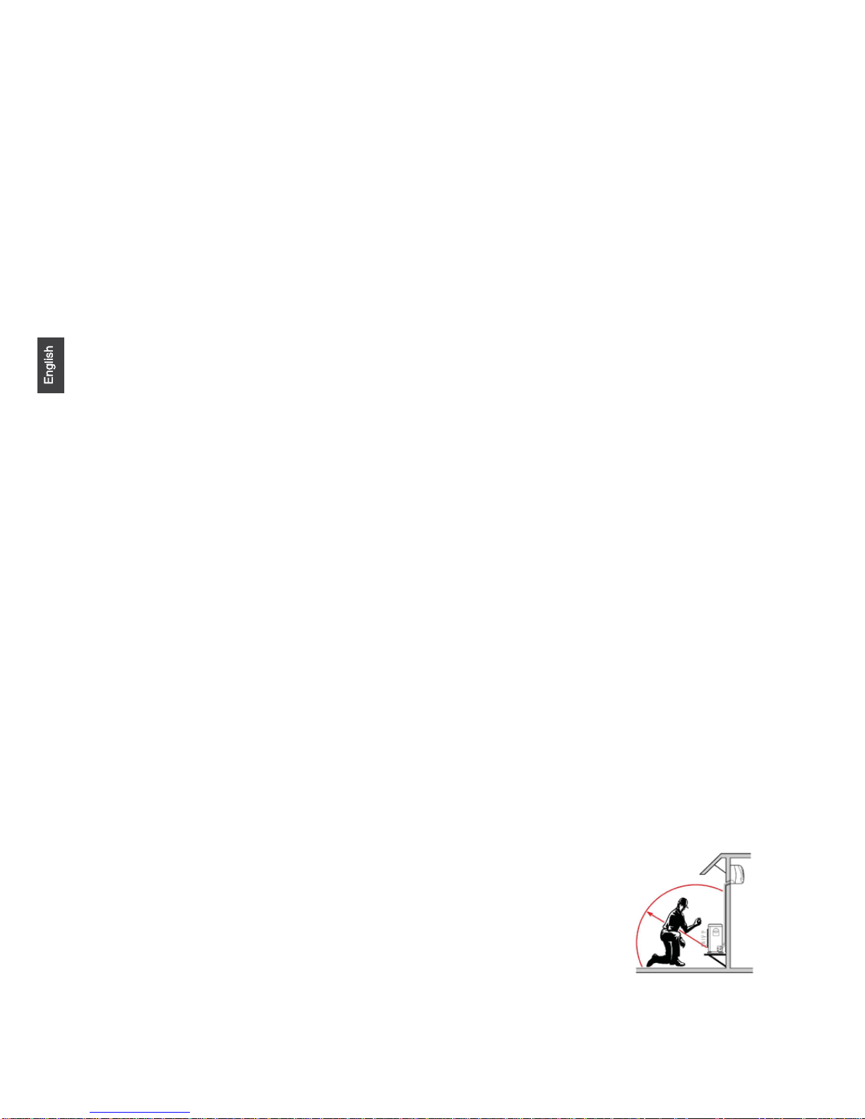
a) Fire source shall be avoided within 3m around the place of installation.
b) The leak detection equipment of refrigerant shall be placed at a low position in the
outdoor, and shall be opened.
5
Page 9
1) Fixation
The support of the outdoor unit shall be fixed onto the wall surface, and then the outdoor unit shall be fixed onto
the support horizontally. In case the outdoor unit is wall-mounted or roof-mounted, the support shall be firmly
fixed, to avoid the damage of strong wind.
2) Installation of connecting pipes
The cone of the connecting pipes shall be aligned with the conical surface of corresponding valve connector.
The nut of connecting pipes shall be installed at a proper position and then be tightened with a spanner. Excessive
tightening torque shall be avoided, or otherwise the nut may be damaged.
• Vacuumizing
A digital vacuum gauge shall be connected for vacuumizing. The duration of vacuumizing shall be at least 15
minutes, and the pressure of the vacuum gauge shall be below 60Pa.Afterwards, the vacuumizing equipment shall
be closed, and whether the reading of the digital vacuum gauge is increased or not shall be observed after the
pressure is maintained for 5 minutes. In case no leakage is identified, the two-way stop valve and three-way stop
valve of the outdoor unit may be opened. Finally, the vacuumizing hose connected to the outdoor unit can be
disassembled.
• Leak Detection
The joint of connecting pipes for the outdoor unit shall be subject to leak detection with soap bubble or
dedicated leak detection equipment.
• Post-installation Inspection Items and Test Run
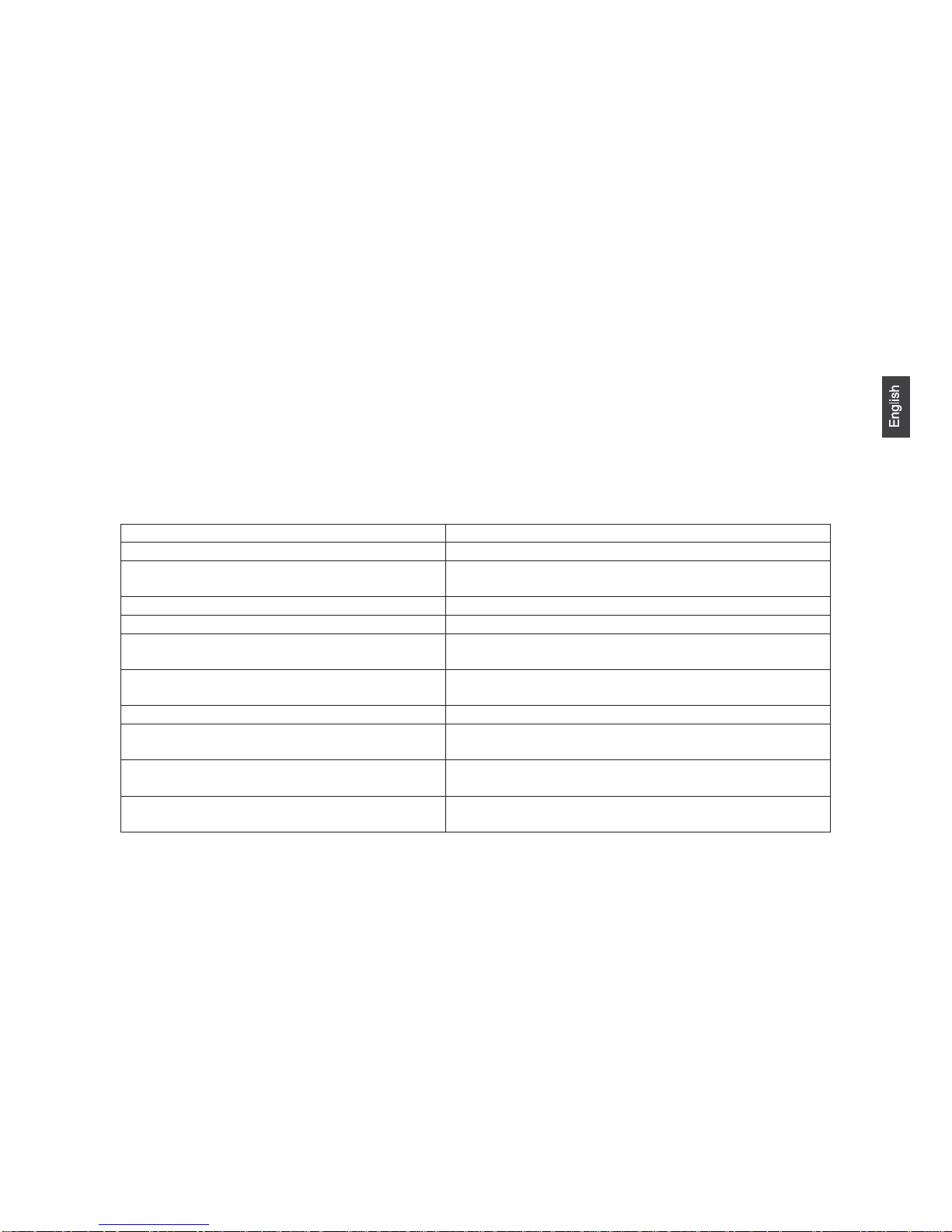
Post-installation Inspection Items
Items to Be Checked Consequence of Improper Installation
Whether the installation is firm or not The unit may fall, vibrate or make a noise
Whether the inspection on air leakage is completed The refrigerating capacity (heating capacity) may be
insufficient
Whether the unit is fully insulated Condensation or drip may occur
Whether the drainage is smooth or not Condensation or drip may occur
Whether the power voltage is identical to that
marked on the nameplate
Failure may occur or the parts may be burned
Whether the circuit and pipeline are installed
correctly
Failure may occur or the parts may be burned
Whether the unit is safely earthed Electric leakage may occur
Whether the type of wire is in line with relevant
regulations
Failure may occur or the parts may be burned
Whether barriers are identified at the air inlet/outlet
of the indoor/outdoor unit
The refrigerating capacity (heating capacity) may be
insufficient
Whether the length of refrigerant pipes and the
refrigerant amount charged are recorded
The refrigerant amount charged cannot be confirmed
Test Run
1. Preparations
(1) Power on is not allowed before all the installation operations are completed and before the leak
detection is proven qualified.
(2) The control circuit shall be connected correctly and all the wires shall be firmly connected.
(3) The two-way stop valve and three-way stop valve shall be opened.
(4) All the scattered articles (especially the metal filing and thread residue) shall be removed from the unit
body.
2. Methods
(1) Switch on the power supply and press the “ON/OFF” on the remote controller, after which the air
conditioner will start operating.
(2) Press “Mode” to select refrigeration, heating and sweeping wind, and observe whether the air
conditioner is under normal operation.
6
Page 10
Relocation Procedures
Note: in case relocation is required, the joint of evaporator gas/liquid pipes of the indoor unit shall be cut off with
a cutting knife. Connection is only allowed after re-flaring (the same to the outdoor unit).
Maintenance Instructions
Maintenance Precautions
Precautions
• For all the faults requiring welding the refrigeration pipelines or components inside the refrigeration system
of R32 refrigerant air conditioners, maintenance at the user’s site is never allowed.
• For the faults requiring radical disassembly and bending operation of the heat exchanger, such as the
replacement of the outdoor unit chassis and integral disassembly of the condenser, inspection and maintenance at
the user’s site are never allowed.
• For the faults requiring replacement of the compressor or parts & components of refrigeration system,
maintenance at the user’s site is not allowed.
• For other faults not involved in the refrigerant container, internal refrigeration pipelines and refrigeration
elements, the maintenance at the user’s site is allowed, including the cleaning and dredging of the refrigeration
system requiring no disassembly of refrigeration elements and no welding.
• In case replacement of gas/liquid pipes is required during maintenance, the joint of evaporator gas/liquid
pipes of the indoor unit shall be cut off with a cutting knife. Connection is only allowed after re-flaring (the same
to the outdoor unit).
Qualification Requirements of Maintenance Personnel
1. All the operators or the maintenance personnel involved in refrigerating circuits shall be provided with the
effective certificate issued by an industry-accepted assessment institute, to ensure that they are qualified for safety
disposal of refrigerant as required in the assessment regulations.
2. The equipment can only be maintained and repaired as per the method recommended by the manufacturer.
In case the assistance from personnel of other disciplines is required, the assistance shall be supervised by the
personnel with qualification certificate involved in flammable refrigerant.
7
Page 11
Inspection on Maintenance Environment
• Before operation, the refrigerant leaked in the room is not allowed.
• The area of the room in which maintenance is made shall be in line with the nameplate.
• Continuous ventilation shall be maintained during maintenance.
• Open fire or high-temperature heat source higher than 548 degree which can easily give birth to open fire is
not allowed inside the room within the maintenance area.
• During maintenance, the phones and the radioactive electronics of all the operators inside the room must be
powered off.
• One dry powder or carbon dioxide extinguisher shall be equipped inside the maintenance area, and the
extinguisher must be under available state.
Maintenance Site Requirements
• The maintenance site shall be provided with favorable ventilation and must be flat. Arrangement of the
maintenance site inside the basement is not allowed.
• Welding zone and non-welding zone shall be divided at the maintenance site, and shall be clearly marked. A
certain safety distance must be guaranteed between the two zones.
• Ventilators shall be installed at the maintenance site, and exhaust fans, fans, ceiling fans, floor fans and
dedicated exhaust duct can be arranged, to meet the requirements of ventilation volume and uniform exhaust, and
to avoid accumulation of refrigerant gas.
• Leak detection equipment for flammable refrigerant shall be equipped, with relevant management system
being established. Whether the leak detection equipment is under available state shall be confirmed before
maintenance.
• Sufficient dedicated vacuum pumps of flammable refrigerant and refrigerant charging equipment shall be
equipped, with relevant management system for maintenance equipment being established. It shall be guaranteed
that the maintenance equipment can only be used for vacuumizing and charging of one type of flammable
refrigerant, and mixed usage is not allowed.
• The master power switch shall be arranged outside the maintenance site, with protective (anti-explosive)
device being equipped.
• Nitrogen cylinders, acetylene cylinders and oxygen cylinders shall be placed separately. The distance
between the gas cylinders above and the working area involved in open fire shall be at least 6m. The anti-backfire
valve shall be installed for the acetylene cylinders. The color of the acetylene cylinders and oxygen cylinders
installed shall meet the international requirements.
• The warning sign of “No Fire” shall be arranged inside the maintenance area.
• Fire control device suitable for electric appliance such as the dry powder extinguisher or carbon dioxide
extinguisher shall be equipped, and shall always be under the available state.
• The ventilator and other electrical equipment at the maintenance site shall be relatively fixed, with
standardized pipe routing. Temporary wires and sockets at the maintenance site are not allowed.
Leak Detection Methods
• The environment in which the refrigerant leakage is checked shall be free from potential ignition source.
Leak detection with halogen probes (or any other detector with open fire) shall be avoided.
• For the system containing flammable refrigerant, leak detection may be realized with electronic leak
detection equipment. During leak detection, the environment in which the leak detection equipment is calibrated
shall be free from refrigerant. It shall be guaranteed that the leak detection equipment will not become potential
ignition source, and is applicable to the refrigerant to be detected. Leak detection equipment shall be set at a
percentage of the LFL of the refrigerant and shall be calibrated to the refrigerant employed, and the appropriate
percentage of gas (25 % maximum) is confirmed.
• The fluid used for leak detection shall be applicable to most of the refrigerant. The use of chlorine-
containing solvent shall be avoided, to avoid chemical reaction between chlorine and refrigerant and corrosion to
copper pipelines.
• In case leakage is suspected, the open fire at the site shall be evacuated or be put out.
• In case welding is required at the leakage position, all the refrigerants shall be recovered, or be isolated at a
position far from the leak point with a stop valve. Before and during welding, the whole system shall be purified
with OFN.
8
Page 12

Safety Principles
• During product maintenance, favorable ventilation shall be guaranteed at the maintenance site, and the close
of all the doors/windows is not allowed.
• Operation with open fire is not allowed, including welding and smoking. The use of phones is also not
allowed. The user shall be informed that cooking with open fire is not allowed.
• During maintenance in a dry season, when the relative humidity is less than 40%, anti-static measures shall
be taken, including the wearing of cotton clothes and cotton gloves.
• In case the leakage of flammable refrigerant is identified during maintenance, forced ventilation measures
shall be taken immediately, and the source of leak shall be plugged.
• In case the product damaged must be maintained by disassembling the refrigeration system, the product
must be delivered to the maintenance point. Welding of refrigerant pipelines at the user’s site is not allowed.
• During maintenance, in case re-treatment is required due to lack of fittings, the air conditioner shall be reset.
• The refrigeration system must be safely earthed in the whole course of maintenance.
• For the door-to-door service with refrigerant cylinders, the refrigerant charged inside the cylinder cannot
exceed the specified value. The cylinder placed in vehicles or at the installation/maintenance site shall be fixed
perpendicularly and be kept away from heat sources, ignition source, source of radiation and electric appliance.
Maintenance Items
Maintenance Requirements
• Before the refrigeration system is operated, the circulating system shall be cleaned with nitrogen. Afterwards,
the outdoor unit shall be vacuumized, the duration of which cannot be less than 30 minutes. Finally, 1.5~2.0MPa
OFN shall be used for nitrogen flushing (30 seconds~1 minute), to confirm the position requiring treatment.
Maintenance of the refrigeration system is only allowed after the residual gas of flammable refrigerant is removed.
• During the use of refrigerant charging tools, cross contamination of different refrigerants shall be avoided.
The total length (including the refrigerant pipelines) shall be shortened as much as possible, to reduce the residual
of refrigerant inside.
• The cylinders of refrigerant shall be kept upright, and be fixed.
• Before refrigerant charging, the refrigeration system shall be earthed.
• The refrigerant charged shall be of the type and volume specified on the nameplate. Excessive charging is
not allowed.
• After maintenance of the refrigeration system, the system shall be sealed with a safe manner.
• The maintenance in progress shall not damage or lower the original class of safety protection of the system.
Maintenance of Electrical Components
• Partial of the electrical component under maintenance shall be subject to inspection on refrigerant leakage
with dedicated leak detection equipment.
• After the maintenance, the components with safety protection functions cannot be disassembled or removed.
• During the maintenance of sealing elements, before opening the seal cover, the air conditioner shall be
powered off first. When power supply is required, continuous leak detection shall be carried out at the most
dangerous position, to avoid potential risks.
• During maintenance of electrical components, the replacement of enclosures shall not affect the level of
protection.
• After maintenance, it shall be guaranteed that the sealing functions will not be damaged or the sealing
materials will not lose the function of preventing the entry of flammable gas due to aging. The substitute
components shall meet the recommended requirements of the air conditioner manufacturer.
Maintenance of Intrinsically Safe Elements
The intrinsically safe element refers to the components working continuously inside flammable gas without any
risks.
• Before any maintenance, leak detection and inspection on earthing reliability of the air conditioner must be
carried out, to ensure no leakage and reliable earthing.
• In case the allowable voltage and current limit may be surpassed during the service of the air conditioner,
any inductance or capacitance cannot be added in the circuit.
• Only the elements appointed by the air conditioner manufacturer can be used as the parts and components
replaced, or otherwise a fire may be triggered in case of refrigerant leakage.
• For the maintenance not involved in system pipelines, the system pipelines shall be well protected, to ensure
that no leakage will be caused due to maintenance.
• After maintenance and before test run, the air conditioner must be subject to leak detection and inspection on
earthing reliability with leak detection equipment or leak detecting solution. It shall be guaranteed that the startup
inspection is carried out without leakage and under reliable earthing.
9
Page 13
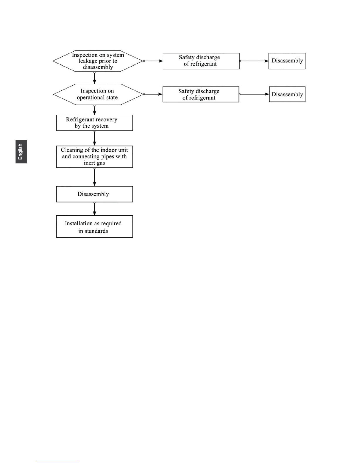
Removal and Vacuumizing
The maintenance or other operations of the refrigeration circuit shall be made as per conventional procedures.
Moreover, the flammability of refrigerant shall also be mainly considered. The following procedures shall be
followed:
• Refrigerant clearing;
• Pipeline purification with inert gas;
• Vacuumizing;
• Pipeline purification again with inert gas;
• Pipeline cutting or welding. The refrigerant shall be recovered to a proper cylinder. The system shall be
purged with OFN, to ensure safety. The step above may need to be repeated for several times. Compressed air or
oxygen cannot be used for purging.
In the course of purging, OFN shall be charged inside the refrigeration system under vacuum state, to reach
the operating pressure. Afterwards, the OFN shall be discharged to the atmosphere. Finally, the system shall be
vacuumized. The step above shall be repeated until all the refrigerants in the system are cleared. The OFN charged
for the last time shall be discharged to the atmosphere. Afterwards, the system can be welded. The operation
above is necessary in case of pipeline welding.
It shall be guaranteed that no alight fire source is around the outlet of the vacuum pump and the ventilation is
favorable.
Welding
• Favorable ventilation must be guaranteed in the maintenance area. After the maintenance machine is subject
to the vacuumizing above, the system refrigerant can be discharged on the outdoor unit side.
• Before the outdoor unit is welded, it must be guaranteed that no refrigerant is inside the outdoor unit and the
system refrigerant has been discharged and cleared.
• The refrigeration pipelines cannot be cut with a welding gun under any circumstance. The refrigeration
pipelines must be disassembled with a pipe cutter, and the disassembly must be carried out around a ventilation
opening.
Refrigerant Charging Procedures
The following requirements are added as the supplementation of conventional procedures:
• During the use of refrigerant charging tools, cross contamination of different refrigerants shall be avoided.
The total length (including the refrigerant pipelines) shall be shortened as much as possible, to reduce the residual
of refrigerant inside;
• The cylinders of refrigerant shall be kept upright;
• Before refrigerant charging, the refrigeration system shall be earthed;
• A label must be pasted on the refrigeration system after refrigerant charging;
• Excessive charging is not allowed; the refrigerant shall be charged slowly;
• In case system leakage is identified, refrigerant charging is not allowed unless the leak point is plugged;
• During refrigerant charging, the charging amount shall be measured with an electronic scale or a spring
scale. The connecting hose between the refrigerant cylinder and the charging equipment shall be relaxed
appropriately, to avoid impact on the measuring accuracy due to stress.
Requirements on storage site of refrigerant
• The cylinder of refrigerant shall be placed in a -10~50°C environment with favorable ventilation, and
warning labels shall be pasted;
• The maintenance tool in contact with the refrigerant shall be stored and used separately, and the
maintenance tool of different refrigerants cannot be mixed.
Scrapping and Recovery
Scrapping
Before scrapping, the technician shall be completely familiar with the equipment and all its features. The safe
recovery of refrigerant is recommended. In case the refrigerant recovered needs to be reused, before which the
sample of refrigerant and oil shall be analyzed. The power supply required shall be guaranteed before tests.
(1) The equipment and operation shall be well known;
(2) Power supply shall be switched off;
(3) The followings shall be guaranteed before scrapping:
• The mechanical equipment shall be convenient for operation on the cylinder of refrigerant (if necessary);
• All personal protective equipment is available and being used correctly;
• The whole course of recovery shall be guided by qualified personnel;
• The recovery equipment and cylinders shall be in line with corresponding standards.
(4) The refrigeration system shall be vacuumized if possible;
10
Page 14
(5) In case the vacuum state cannot be reached, vacuumizing shall be carried out from numerous positions, to
pump the refrigerant in each part of the system out;
(6) It shall be guaranteed that the capacity of cylinders is sufficient before recovery;
(7) The recovery equipment shall be started and operated as per the operation instructions of the manufacturer;
(8) The cylinder cannot be charged too full. (The refrigerant charged cannot exceed 80% of the capacity of
cylinders)
(9) The maximum operating pressure of cylinders cannot be surpassed even only lasting for a short term;
(10) After refrigerant charging is completed, the cylinder and equipment must be evacuated rapidly, and all the
stop valves on the equipment must be closed;
(11) Before purification and tests, the refrigerant recovered cannot be charged into another refrigeration system.
Note:
The air conditioner shall be marked (with dates and signature) after being scrapped and the refrigerant is
discharged. It shall be guaranteed that the sign on the air conditioner can reflect the flammable refrigerant
charged inside.
Recovery
During maintenance or scrapping, the refrigerant inside the refrigeration system needs to be cleared. It is
recommended that the refrigerant be cleared thoroughly.
The refrigerant can only be charged into a dedicated cylinder, the capacity of which shall match with the
refrigerant amount charged in the whole refrigeration system. All cylinders to be used are designated for the
recovered refrigerant and labeled for that refrigerant (Dedicated Cylinder for Refrigerant Recovery). The cylinders
shall be equipped with pressure relief valves and stop valves under favorable state. The empty cylinder shall be
vacuumized before usage and be kept under normal temperature if possible.
The recovery equipment shall always be under favorable working state, and be equipped with operation
instructions, to facilitate information search. The recovery equipment shall be applicable to the recovery of
flammable refrigerant. Moreover, weighing apparatus under available state with measurement certificates shall be
equipped. In addition, removable attachment joints free from leakage shall be used as the hose, and shall always
be under favorable state. Whether the recovery equipment is under favorable state and is properly maintained and
whether all the electrical components are sealed shall be checked before usage, to avoid fire in case of refrigerant
leakage. If you have any question, please consult the manufacturer.
The refrigerant recovered shall be delivered back to the manufacturer in appropriate cylinders, with
transporting instructions being attached. Mixing of refrigerant in recovery equipment (especially the cylinders) is
not allowed.
During transporting, the space in which the flammable refrigerant air conditioners are loaded cannot be
sealed. Anti-static measures shall be taken for the transporting vehicles if necessary. Meanwhile, during the
transporting, loading and unloading of air conditioners, necessary protective measures shall be taken, to protect
the air conditioner from being damaged.
During removal of the compressor or clearing of the compressor oil, it shall be guaranteed that the
compressor is vacuumized to a proper level, to ensure no residual flammable refrigerant is left inside the
lubricating oil. The vacuumizing shall be completed before the compressor is delivered back to the manufacturer.
The vacuumizing can only be accelerated by heating the compressor housing through electrical heating. Safety
shall be guaranteed when the oil is discharged from the system.
11
Page 15

Please be subject to the actual product purchased.
The above indoor and outdoor units’ picture is just for your reference.
F
A
C
E
D
Optional parts for piping
Non-adhesive tape
Adhesive tape
Saddle (L.S) with screws
Connecting electric cable
for indoor and outdoor
Drain hose
Heating insulating material
Piping hole cover
Fixing of outdoor unit
Fix the unit to concrete or block
withbolts(10mm)andnuts rmly
and horizontally.
When
tting the unit to wall
surface, roof or rooftop, x
a supporter surely with nails
or wires in consideration of
earthquake and strong wind.
If vibration may affect the
house, x the unit by attaching a
vibration-proof mat.
The marks from to
in the
gure are the
parts numbers.
The distance between
the indoor unit and the
oor should be more
than 2m.
ThemodelsadoptHFCfreerefrigerantR32.
more than
10cm
more than 15cm
more than 10cm
more than 20cm
more than
20cm
more than 25cm
more than
60cm
A
G
A
F
C
E
D
G
B
Arrangement of piping
directions
Rear left
Left
Rear
right
Right
Below
G
Attention must be paid to
the rising up of drain hose
Indoor/Outdoor Unit Installation Drawings
For installation of the indoor units,refer to the installation manual which was provided with the units.
(The diagram shows a wall-mounted indoor unit.)
AIR OUTLET
AIR INLET
CONNECTING PIPING AND ELECTRICAL WIRING
DRAIN HOSE
4
Compressor(Inside of Unit)
12
If using the left side drain pipe, make sure the hole is got through.
Page 16

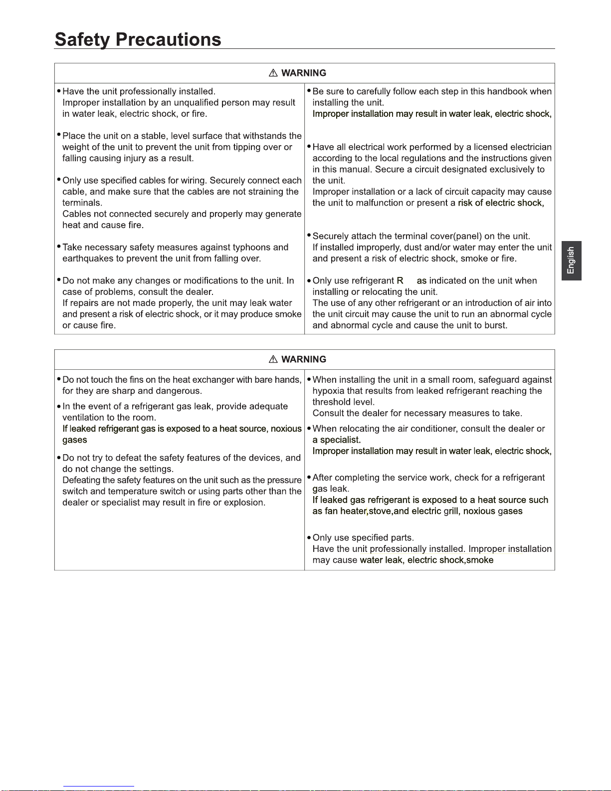
WARNING
CAUTION
Open the window and well ventilated the room
explosion-proof fuse
13
Page 17
32
3
, fire or explosion will be caused.
fire or explosion.
fire or explosion.
fire or explosion.
, fire
or explosion.
,fire,explosion.
14
Page 18
R32
23R23R
R32
R32
R32
R32
R32
15
Page 19
Without a breaker for current leakage will cause risks
of electric shock, fire or explosion.
Install a explosion-proof breaker for current leakage at the
power source to avoid the risk of the electric shock.
Do not use large-capacity fuses,steel wire,or copper wire.
Damaging the unit ,fire,smoke or explosion will be
caused otherwise.
16
Page 20
R32
R32
R32
R32
R32
R32
R32
R32
R32
17
Page 21

3
R32
R32
R32
R32
R32
R32
R32
18
Page 22

R32
R32
R32
R32
R32
R32
R32
R32
10A
HFC
410A
19
Page 23

NO
Wind direction
Air outlet
Model W D H L1 L2 L3
1U25S2SQ1FA 780 290 597 500 130/150 317
1U35S2SQ1FA 780 290 597 500 130/150 317
1U50S2SR1FA 890 353 697 628 130 355.5
1U71S2SR1FA 890 353 697 628 130 355.5
1U25BEFFRA 780 245 540 500 140 256
1U35BEFFRA 780 245 540 500 140 256
1U50JEFFRA 820 338 614 590 114.2 324
1U68REFFRA 890 353 697 628 130 355.5
1U25S2PJ1FA 820 338 614 590 114 324
1U35S2PJ1FA 820 338 614 590 114 324
Cushion rubber
4.Installation dimension(Unit:mm)
20
Page 24
Amax Bmax C D E
21
1U50S2SR1FA
1U7S2SR1FA
1U50JEFFRA
1U68REFFRA
10 15 5 7
7
20
1U25S2SQ1FA
1U35S2SQ1FA
1U25BEFFRA
1U35BEFFRA
1U50S2SR1FA
1U7S2SR1FA
1U50JEFFRA
1U68REFFRA
1.
Outdoor unit
Indoor unit
A
B
Outdoor unit
Indoor unit
A
B
A
B
Outdoor unit
Indoor unit
Oil trap
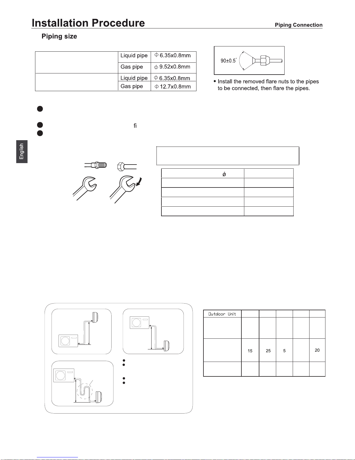
To bend a pipe, give the roundness as large as possible not to crush the pipe ,
and the bending radius should be 30 to 40
mm or longer.
Connecting the pipe of gas side
rst makes working easier.
TheconnectionpipeisspecializedforR32.
Half union
Flare nut
Torque wrench
CAUTION
Be careful that matters, such as wastes of sand
s,water,
, etc. shall not enter the pipe.
ThestandardpipelengthisCm.IfitisoverDm,thefunctionoftheunitwillbeaffected.Ifthepipe
has
to be lengthened, the refrigerant should be charged,
according to E g/m. But the charge of refrigerant
must
be conducted by profes
sional air conditioner engineer. Before adding additional refrigerant,
perform
air
purging from the refrigerant pipes and indoor unit using a vacuum pump,then
Spanner
Forced fastening without careful centering may
damage the threads and cause a leakage of gas.
Pipe Diameter( ) Fastening torque
Liquid side6.35mm(1/4") 18N.m
Liquid/Gas side9.52mm(3/8") 42 N.m
Gas side 12.7mm(1/2") 55N.m
Gas side 15.88mm(5/8") 60 N.m
Max.Elevation:
In case the elevation A is more
than 5m, oil trap shoud be
installed every 5~7
Max. Length:
In case the pipe length B is
more thanDm, the refrigerant
should be charged, according
to E g/m.
Connection of pipes
charge
additional refrigerant.
Amax
Bmax
2.
1U25S2SQ1FA
1U35S2SQ1FA
1U25BEFFRA
1U35BEFFRA
1U25S2PJ1FA 1U35S2PJ1FA
10 15 5 2010
1U25S2PJ1FA
1U35S2PJ1FA
Page 25

22
Page 26

23
(R32)
(R32)
Page 27

Outdoor unit
To Indoor unit
To Indoor unit
FOR
Outdoor unit
FOR
20 3015 1.0201
20 30
15
1.5
201
30
2.5
25
25
20
1
ceramic type of T 25A/250V.
The explosion-proof breaker of the air conditioner should be all-pole switch. The distance between its two contacts should not be no
A explosion-proof breaker must be installed.
24
1U25S2SQ1FA
1U35S2SQ1
FA
1U25BEFFRA
1U35BEFFRA
1U50S2SR1FA
1U71S2SR1FA
1U50JEFFRA
1U68REFFRA
1U25S2SQ1FA
1U35S2SQ1FA
1U25BEFFRA
1U35BEFFRA
1U25S2SQ1FA
1U35S2SQ1FA
1U25BEFFRA
1U35BEFFRA
1U50S2SR1 FA
1U71S2SR1 FA
1U50JEFFRA
1U68REFFRA
1U50S2SR1FA
1U71S2SR1FA
1U50JEFFRA
1U68REFFRA
POWER
1U25S2PJ1FA
1U35S2PJ1FA
1U25S2PJ1FA
1U35S2PJ1FA
1U25S2PJ1FA
1U35S2PJ1FA
.
Model
Connecting wiring
Power cable
3G2.5mm
2
3G1.0mm
2
3G1.5mm
2
4G
1.0
mm
2
4G
1.0
mm
2
4G
1.0
mm
2
1(N) 2(L)
3(C)
{
POWER
Page 28

3
Outdoor Unit
2
9
15
8
12
10
5
13
19
1
18
4
11
25
25
25
110
Haier
Address:No.1 Haier Road,Hi-tech Zone,Qingdao 266101 P.R.ChiQD
Contacts: TEL +86-532-8893-6943;FAX +86-532-8893-1010
Website: www.haier.com
Suction temperature sensor failure
When the The wiring of compressor is wrong or
the connection is poor
17
16
15
Lack of refrigerant
Check if there is leakage in the unit.
m
25
Page 29

Contenido
Requisitos de Carga y Descarga / Gestión de Transporte / Almacenamiento ..........................3
Instrucciones de Instalación .....................................................................................................3
Procedimiento de Trasladar la Unidad .....................................................................................7
Instrucciones de Mantenimiento ...............................................................................................7
Deshecho y Recuperación ............................................ ...........................................................10
Dibujos de instalación de las unidades interior y exterior.. ....................................................... 12
Precauciones de seguridad ......................................................................................................13
Leer antes de realizar la instalación .........................................................................................17
Procedimiento instalación .........................................................................................................20
Resolución de problemas en la unidad exterior.................................................... .....................25
ADVERTENCIA ........................................................................................................................1
Page 30

Lea las precauciones en este manual
detalladamente antes de utilizar la unidad.
Este aparato está cargado de R32.
Guarde este manual en el lugar donde el usuario puede encontrar fácilmente.
ADVERTENCIA:
Ÿ Pida a su distribuidor o personal calificado para realizar el trabajo de instalación. No intente instalar el aire
acondicionado por usted mismo. La instalación incorrecta puede provocar fugas de agua, descargas eléctricas o
incendios.
Ÿ Instale el aire acondicionado de acuerdo con las instrucciones en este manual de instalación.
Ÿ Asegúrese de utilizar solamente los accesorios y partes especificados para el trabajo de instalación.
Ÿ Instale el aire acondicionado en una base suficientemente fuerte para soportar el peso de la unidad.
Ÿ El trabajo eléctrico debe ser realizado de acuerdo con las regulaciones locales y nacionales pertinentes y de
acuerdo con las instrucciones de este manual de instalación. Asegúrese de usar el circuito solamente para la
alimentación. El método de cableado debe cumpl ir el estándar de cableado local. El tipo de cable de conexión es
H07RN-F.
Ÿ Use un cable de longitud adecuada. No use el cable dividido o el cable prolongado que puede causar el
sobrecalentamiento, la descarga eléctrica o el incendio.
Ÿ Todos los cables deben haber conseguido el certif icado de autenticación europea. Durante l a instalación, cuando
los cables de conexión se rompen, debenasegurarse de que el cable de tierra es el último de romperse.
Ÿ Si existe la fuga de gas de refrigerante durante la instalación, hay que ventilar el área inmediatamente. Si el
refrigerante tiene contacto con fuego se puede producir el gas tóxico.
Ÿ Después de terminar la instalación, de bencomprobar la fuga del gas refrigerante
Ÿ Al instalar o trasladar el aire acondicionado, deben evacuar el circuito de refrigerante para asegurarse de que el
circuito esté libre de aire y deben usar solamente el refrigerante especificado (R32).
Ÿ Asegúrese de que la toma de tierra es correcta y fiable. No ponga la unidad a la tubería de servicios públicos, al
conductor de iluminación o la toma de tierra de teléfono. La toma de tierra imperfecta puede causar la descarga
eléctrica.
Ÿ Asegúrese de que un interruptor de fuga a tierra esté instalado.
Ÿ El interruptor del aire acondicionado debe ser el interruptor multipolar; y la distancia entre sus dos contactos no
debe ser inferior a 3 mm. Tales métodos para desconexión deben ser incorporados en el cableado.
Ÿ No utilice otros métodos para acelerar el proceso de desescarche o para limpiar, aparte de los recomendados por
el fabricante.
Ÿ El aparato se debe almacenar en el interior sin fuentes de ignición en operación continua (por ejemplo: llamas
abiertas, un aparato de gas en operación o un calentador eléctrico en operación).
Ÿ No perfore ni queme.
Ÿ Tenga en cuenta que posiblemente el refrigerante no tenga olor.
Ÿ El aparato se debe instalar, operar y almacenar en una habitación con una superficie mayor que 3,0m
2
. La
habitación debe ser bien ventilada.
Ÿ Cumpla con las regulaciones nacionales de gas.
Ÿ Este aparato se puede utilizar por e l niño de 8 años o mayor y la persona con reducida capacidad física, sensorial
o mental o falta de experiencia y conocimiento si están bajo la supervisión o saben las instruccione s de usar el
aparato con una manera segura y saben los peligros involucrados. Los niños no deben jugar con el aparato. La
limpieza y el mantenimiento del aparato no deben ser realizados por los niños sin supervisión.
Ÿ El aire acondicionado no debe ser abandonado donde quiere usted. Si usted tiene la necesidad, por favor póngase
en contacto con el personal de servicio de Haier para conseguir los métodos correctos para tratar.
1
Page 31

CONFORMIDAD DE LOS MODELOS
SEGÚN LAS NORMATIVAS EUROPEAS
CE
Todos los productos satisfacen los requisitos de las siguientes
normas europeas:
- Directiva de baja tensión,
2014/35/EU
- Compatibilidad electromagnética 2014/30/EU
ROHS
Los productos satisfacen los requisitos de la directiva 2011/65/EU
establecida por el Parlamento Europeo y el Consejo sobre
restricciones a la utilización de determinadas sustancias peligrosas
en aparatos eléctricos y electrónicos (Directiva RoHS UE).
WEEE
De acuerdo con la directiva 2012/19/EU del Parlamento Europeo,
se informa al consumidor acerca de los requisitos de eliminación
de productos eléctricos y electrónicos.
REQUISITOS DE ELIMINACIÓN:
Su aparato de aire acondicionado ha sido
marcado con este símbolo, el cual significa que
los productos de tipo eléctrico y electrónico
no deben mezclarse con residuos domésticos
sin clasificar. No intente desmontar el sistema
personalmente: tanto el desmontaje del sistema de aire
acondicionado como la manipulación del refrigerante, el
aceite y cualquier otro componente deben ser llevados
a cabo por un instalador capacitado, de acuerdo con la
legislación local y nacional al efecto. Los aparatos de aire
acondicionado deben ser manipulados en instalaciones de
manipulación especializadas y aptas para su reutilización,
reciclado y recuperación. Al garantizar la correcta
eliminación de este producto, usted contribuirá a evitar las
posibles consecuencias negativas que podría provocar
sobre el medioambiente y la salud humana. Póngase en
contacto con el instalador o la autoridad local pertinente
si desea obtener más información. Las pilas deben ser
extraídas del mando a distancia y eliminadas de forma
independiente, de acuerdo con la legislación local y nacional
al efecto.
INFORMACIÓN IMPORTANTE ACERCA DEL REFRIGERANTE UTILIZADO
1
1+2=
kg
R32
2
kg
2=
1=
B
C
D
FE
kg
A
Este producto contiene gases fluorados de efecto invernadero
regulados por el Protocolo de Kioto. No los libere libremente a la
atmósfera.
Tipo de refrigerante: R32
Valor GWP*: 675
GWP = Potencial de contribución al calentamiento global
Escriba con tinta indeleble:
1 la carga de refrigerante que contiene el producto de fábrica
2 la cantidad de refrigerante adicional cargada durante la
instalación y
2 la carga total de refrigerante
en la etiqueta de carga de refrigerante suministrada con el
producto.
Una vez escritos los datos correspondientes, la etiqueta deberá
adherirse cerca de la conexión de carga del producto (por ejemplo,
sobre la parte interna de la cubierta de la válvula de retención).
A Contiene gases fluorados de efecto invernadero regulados por el
Protocolo de Kioto.
B Carga de refrigerante que contiene el producto de fábrica:
consulte la placa de características de la unidad.
C Cantidad de refrigerante adicional cargada durante la instalación.
D Carga total de refrigerante.
E Unidad exterior.
F Botella de refrigerante y colector de carga.
regulados por el Protocolo de Kioto.
Clima: T1 Tensión: 230V
CAUCIÓN:
Ÿ No instale el aire acondicionado en cualquier lugar donde existe peligro de fuga de gas inflamable.
Ÿ En el caso de fuga de gas, la acumulación de gas cerca del aire acondicionado puede provocar el incendio. Apriete
la tuerca de acuerdo con el método especificado como por ejemplo usar una llave de torsión. Si la tuerca está
demasiado apretada, posiblemente se agrietará después de un largo tiempo de uso y se provocará la fuga de
refrigerante.
Ÿ Tome medidas adecuadas para proteger la unidad exterior como por ejemplo usar un protector contra animales
pequeños. Los animales pequeños hacen el contacto entre las partes eléctricas que puede causar mal
funcionamiento, humo o fuego.
Ÿ Por favor, avise al cliente que deba mantener la limpieza del área cercano de la unidad.
Ÿ La temperatura del circuito de refrigerante será alta, por favor separe los cables de unidades de los tubos de
cobre que no son térmicamente aislados.
Ÿ Sólo se permite a la persona calificada a manejar, cargar, evacuar y tratar el refrigerante.
2
Page 32

Requisitos de Carga y Descarga / Gestión de Transporte / Almacenamiento
Requisitos de Carga y Descarga
1) Al cargar y descargar los productos, deben tomarlos y ponerlos cuidadosamente.
2) Se prohíbe las operaciones violentas y brutales, tales como acocear, lanzar, estrellar, chocar, arrastar y rodar,
etc.
3) Deben capacitar a los estibadores para que ellos conozcan los peligros causados por la carga y el transporte
brutales.
4) En el lugar de carga y transporte y descarga deben equiparse con los extintores de polvo químico seco o los
dispositivos adecuados de extinción de incendios que están en el plazo de validez.
5) Los personales sin capacitación se prohíben servirse para los trabajos de carga y descarga de los aires
acondicionados de refrigerantes inflamables.
6) Antes de la carga y descarga, deben tomar las medidas antiestáticas. Y durante la carga y descarga se
prohíbe contestar el teléfono.
7) Se prohíbe fumar o usar llama abierta alrededor del aire acondicionado.
Requisitos de Gestión de Transporte
1) La máxima cantidad de transporte de los productos finales se determina según las leyes reglamentarias
locales.
2) Los vehículos de transporte utilizados se determinan según las leyes reglamentarias locales.
3) Para los servicios de mantenimiento, deben usar los vehículos especiales para servicios de postventa. Las
botellas de refrigerantes y los productos para la reparación no se pueden transportar exponiendo al aire libre.
4) Los sobrecielos o los materiales similares para la protección de los vehículos de transporte deben
caracterizarse por cierta propiedad ignífuga.
5) En las carrocerías no abiertas, deben instalarse los dispositivos de alarma de fugas de refrigerantes
inflamables.
6) Las carrocerías de los vehículos de transporte deben equiparse con los dispositivos antiestáticos.
7) En la cabina de los vehículos deben llevar los extintores de polvo químico seco o los dispositivos adecuados
de extinción de incendios que están en el plazo de validez.
8) En los lados y la parte de atrás de los vehículos de transporte deben pegarse tiras reflectantes de colores
anaranjado y blanco o de colores rojo y blanco para advertir los vehículos de atrás que mantengan la distancia.
9) Durante el transporte, deben presentar atención a adelantar a velocidad uniforme para evitar la aceleración
repentina o el frenazo.
10) Se prohíbe transportar los bienes inflamables o los bienes fáciles de generar electricidad estática en el mismo
vehículo.
11) Durante el transporte, no acerque a las zonas de alta temperatura. Si la temperatura interior de la carrocería
es demasiado alta, deben tomar las medidas necesarias para disipar el calor.
Requisitos de Almacenamiento
1) Los empaques para el almacenamiento de los equipos deben servirse para evitar las fugas de refrigerantes
causadas por las destrucciones mecánicas de los equipos interiores.
2) La máxima cantidad de los equipos que se permiten almacenar juntos se determina según las leyes
reglamentarias locales.
Instrucciones de Instalación
Precauciones de Instalación
¡ADVERTENCIA!
ƾ El aire acondicionado de refrigerantes R32 no se puede instalarse en el cuarto del usuario donde la superficie
es menor que la mínima establecida en la siguiente tabla. A fin de prevenir que la densidad de refrigerantes en el
espacio interior supera al valor establecido por las fugas de refrigerantes del sistema de enfriamiento de la unidad
interior del aire acondicionado.
ƾ Se prohíbe usar de otra vez el niple de campana de tubería de conexión tras la fijación (influyendo en la
estanqueidad).
ƾ Para los cables de conexión de las unidades exterior e interior, deben usar un cable de conexión completo y
sin juntas de acuerdo con las especificaciones de operación de tecnologías de instalación y los requisitos de las
instrucciones.
Mínima superficie del cuarto
Tipo
LFL
k
g/m
3
ham
Masa total de carga /kg
Mínima su
p
erficie del cuarto /
m
2
R32 0,306
1,224 1,836 2,448 3,672 4,896 6,12 7,956
0,6 29 51 116 206 321 543
1,0 10 19 42 74 116 196
1,8 3 6 13 23 36 60
2,2 2 4 9 15 24 40
3
La máxima cantidad de carga de refrigerante (M)
Mkg Mkg
1.0
1.1
1.45
0.9
0.92
1.35
1.6
0.95 0.95
1.6
1U25S2SQ1FA
1U35S2SQ1FA
1U50S2SR1FA
1U71S2SR1FA
1U25BEFFRA
1U35BEFFRA
1U50JEFFRA
1U68REFFRA
1U25S2PJ1FA
1U35S2PJ1FA
modelo de unidad
modelo de unidad
Page 33

Conciencia de Seguridad
1. Procedimiento: realizan los trabajos según un procedimiento controlado para minimizar la probabilidad de
producir riesgos.
2. Zonas: realizan la zonificación para evitar trabajar en espacios cerrados y garantizar el aislamiento adecuado.
Antes de abrir el sistema de enfriamiento o realizar el tratamiento térmico, deben garantizar la ventilación o la
apertura de las zonas.
3. Inspección del sitio: inspección de refrigerantes.
4. Extinción de incendios: colocan los extintores en lugares cercanos. Se prohíben las fuentes de fuego o la alta
temperatura y se establecen las marcas de ¨No Fumar¨.
Inspección Abriendo las Cajas
1. Unidad interior: para la unidad interior (en el evaporador), al salir de la fábrica se ha secuestrado el
nitrógeno. Al abrir las cajas de empaque, primero inspeccione el tapón plástico de color verde del tubo de gas del
evaporador de la unidad interior. En su cubierta superior existe la marca de color rojo, si la marca de color rojo
sobresale, significa que existe el nitrógeno en el interior. Luego inspeccione el tapón plástico de color negro de la
interfaz del tubo de líquido del evaporador de la unidad interior presionando con un destornillador de estrella para
comprobar si existe el nitrógeno. Si la unidad interior no surge el nitrógeno, significa que la unidad interior existe
las fugas. Por lo tanto no puede instalarse.
2. Unidad exterior: introduzca el detector de fugas en la caja del empaque de la unidad exterior para
inspeccionar si existen las fugas de refrigerantes. Si existen las fugas de refrigerantes, no puede instalarse. Se
necesita transportar al Departamento de Mantenimiento.
Inspección de Ambiente de Instalación
1. Inspeccione la superficie del cuarto. La superficie no puede ser menos que la establecida en la etiqueta de
advertencia en la unidad interior.
2. Inspeccione el ambiente alrededor del lugar de instalación. La unidad exterior del aire acondicionado de
refrigerantes inflamables no puede instalarse en el espacio reservado de edificios cerrados.
3. Bajo la unidad interior, no puede existir la fuente de alimentación y los interruptores u otros objetos de alta
temperatura, tales como la fuente de fuego, el calentador de aceite, etc.
4. La fuente de alimentación debe tener el cable de puesta a tierra y ser de puesta a tierra confiable.
5. Al perforar los agujeros de la pared con taladro elétrico, deben confirmar con anticipación si el lugar
reservado por el usuario existe las tuberías enterradas de agua, electricidad y gas. Sólo pueden construir si no
existe la situación mencionada. Recomiendan utilizar los agujeros de la pared reservados en la casa.
Principios de Seguridad de Instalación
1. Garantice la buena ventilación del lugar de instalación (abriendo las ventanas y las puertas).
2. En la zona de refrigerantes inflamables, se prohíbe aparecer la llama abierta o la fuente de calor con
temperatura superior a 548ć, incluidos soldadura, fumar y tostador, etc.
3. Tome las medidas antiestáticas, tales como: vestirse ropas de algodón puro y enguantarse los guantes de
algodón puro, etc.
4. Seleccione los lugares fáciles para la instalación o para el mantenimiento. No puda seleccionar los lugares
cerca a la fuente de calor o en ambiente combustible y explosivo.
5. Durante la instalación, si existe la fuga de refrigerantes de la unidad interior, cierre la válvula de la unidad
exterior inmediatamente y abra las ventanas para la ventilación. Todos los personales deben salir del interior. Tras
la fuga completa de refrigerantes, realice la detección de la densidad para el ambiente del interior. Sólo pueden
tratarlo hasta que la densidad llegue al nivel de seguridad.
6. Si el producto se ha dañado, se necesita transportar al punto de mantenimiento para el tratamiento. Se
prohíbe realizar las operaciones de soldar los tubos de refrigerantes en el lugar del usuario.
7. El lugar para instalar el aire acondicionado debe ser fácil para la instalación o el mantenimiento. Y al
alrededor de las salidas y entradas de aire de las unidades exterior e interior no pueden existir los obstáculos.
También necesitan evitar existir productos eléctricos, interruptores de fuente de alimentación, tomacorrientes,
objetos de valor y productos de alta temperatura bajo el alcance de las líneas laterales de ambos lados de la unidad
interior.
Cuidado con la
electricidad estática
Sin fuente de fuego alrededor
del lugar de instalación
Ropas de
algodón puro
Guantes
antiestáticos
Gafas de seguridad
4
Lea el manual de operador
Lea el manual técnico
Manual de operador; instrucciones de operación
Page 34

• Requisitos de Seguridad Eléctrica
Atención:
1. Al realizar el cableado eléctrico, deben prestar atención a las condiciones alrededores (temperatura
ambiental, luz directa de sol, lluvia, etc.) y realizar la protección eficaz.
2. Para los cables de alimentación y los cables de conexión deben utilizar los cables de núcleo de cobre
cumplidos con las disposiciones de las normas locales.
3. La unidad interior y la unidad exterior deben ser de puesta a tierra confiablemente.
4. Primero conecte los cables de la unidad exterior, luego conecte los cables de la unidad interior. Después de
terminar el cableado y la conexión de los tubos coordinados del aire acondicionado, conecte la fuente de
alimentación del aire acondicionado.
5. Necesitan ser de circuito ramal especial y contar con dispositivos de protección de fugas de electricidad de
suficiente capacidad.
• Requisitos de Cualificación de los Instaladores
Adquieren la cualificación relacionada de acuerdo con las disposiciones de las leyes locales del país.
• Instalación de Unidad Interior
1. Fijación de placa de pared y disposición de tuberías
Para la unidad interior, al utilizar la manera de instalación de izquierdo tubo saliente o derecho tubo saliente,
si la interfaz del evaporador de la unidad interior y el niple de campana de la tubería de conexión no pueden
extender al lado exterior para la instalación, conecte el tubo de conexión de la unidad con la interfaz de la tubería
del evaporador de la unidad interior utilizando la tecnología de niple de campana.
2. Disposición de tuberías
Al disponer el tubo de conexión, la manguera de drenaje y los cables de conexión de unidad, la manguera de
drenaje debe colocarse por abajo, los cables de conexión deben colocarse en arriba, los cables de fuente de
alimentación y los cables de conexión de unidad no se pueden cruzar y enrollar, y para el tubo de drenaje (en
particular en el interior y en la máquina) necesita enrollar los materiales de aislamiento térmico para el tratamiento
de conservación de calor.
3. Detección de fugas inyectando el nitrógeno y manteniendo la presión
Tras conectar el evaporador de la unidad interior y el tubo de conexión (después de la soldadura) y ajustarlo
por la válvula de reducción de presión de la botella de nitrógeno, inyecte el nitrógeno de presión superior a 4,0
MPa en el evaporador y la tubería de conexión y luego cierre la válvula de la botella de nitrógeno. Realice la
detección de fugas por jabonaduras o detector de fugas. Observe si la presión del sistema baja manteniendo la
presión por lo menos de 5 minutos. Si la presión baja, significa que existen las fugas. Después de tratar los puntos
de fuga, repita los procesos de detección de fugas inyectando el nitrógeno y manteniendo la presión.
Tras realizar la detección de fugas inyectando el nitrógeno y manteniendo la presión después de conectar el
evaporador de la unidad interior y la tubería de conexión, conecte la válvula globo de dos vías y la de tres vías de
la unidad exterior y atornille el tapón de cobre de la tubería de conexión. Luego inyecte el nitrógeno de presión
superior a 4,0 MPa por la manguera de inyección en la boca de mantenimiento de la válvula globo de tres vías de
la unidad exterior y luego cierre la válvula de botella de nitrógeno. Realice la detección de fugas por jabonaduras
o detector de fugas. Observe si la presión del sistema baja manteniendo la presión por lo menos de 5 minutos. Si
la presión baja, significa que existen las fugas. Después de tratar los puntos de fuga, repita los procesos de
detección de fugas inyectando el nitrógeno y manteniendo la presión.
Las operaciones mencionadas también puede realizarse después de conectar la unidad interior y la tubería y
conectar la válvula globo de dos vías y la de tres vías de la unidad exterior. Conecte la botella de nitrógeno y el
manómetro en la boca de mantenimiento de la unidad exterior, y luego de inyectar el nitrógeno de presión
superior a 4,0 Mpa, detecte si existen fugas manteniendo la presión por 5 minutos. Inspeccione completamente la
interfaz de la unidad interior o la interfaz de soldadura y la interfaz de tubería de conexión de la válvula globo de
dos vías y la de tres vías de la unidad exterior, y se prohíbe existir puntos de fuga. Sin embargo, al instalar,
necesitan garantizar que todos los conectores están en el estado para la detección de fugas.
Al terminar los procesos anteriores de operación (la detección de fugas inyectando el nitrógeno y
manteniendo la presión es normal), entre en el próximo proceso de operación: escape de aire por el vacío con la
bomba de vacío.
• Instalación de Unidad Exterior
1. Conexión de instalación y fijación
Atención:
a) Garantice que no existe la fuente de fuego al alcance de 3 metros alrededor del lugar de instalación.
b) El detector de fuga de refrigerantes debe colocarse en el lugar más bajo acerca del exterior y estar en estado
abierto.
5
Page 35

1) Fijación de instalación
Fije el soporte de la unidad exterior en la pared, luego fije la unidad exterior en el soporte de la unidad y mantenga
en el nivel horizontal. Si se instala en la pared o el techo, fije bien el soporte para prevenir la invasión del viento
fuerte.
2) Tubo de conexión de instalación
La boca cónica del tubo de conexión debe apuntar a la superficie cónica correspondiente del conector de la
válvula.
Atornille la tuerca del tubo de conexión y luego atorníllela con la llave. El torque de atornillar no puede ser
demasiado grande, de lo contrario, podrá dañar la tuerca.
• Vacío
Para la extracción de vacío, necesitan conectar con el vacuómetro digital. El vacío por lo menos debe durarse por
15 minutos y la presión del vacuómetro debe ser menos que 60Pa. Cierre el equipo de vacíoy observe si la lectura
del vacuómetro digital vuelve a subir tras esperar 5 minutos manteniendo la presión. Después de confirmar no
existir fugas, podrán abrir la válvula globo de dos vías y la de tres vías de la unidad exterior. Luego desmonte la
manguera de vacío conectada a la unidad exterior.
• Detección de Fugas
Realice la detección de fugas para los conectores de los tubos de conexión de la unidad exterior. Podrá realizar la
detección de fugas por el método de detección de fugas sencillo de burbujas o utilizando el detector de fugas
especial.
• Ítems de Inspección tras la Instalación y Puesta en Marcha
Ítems de inspección tras la instalación
Ítems para inspeccíonar Situación probable de producir si se instala incorrectamente
¿Si se instala confiablemente? La unidad podrá caerse, vibrarse o producir ruidos.
¿Si se inspeccionan las fugas de gases? Podrá causar el insuficiente volumen de enfriamiento
(calefacción)
¿Si la unidad tiene suficiente aislamiento térmico? Podrá causar la condensación de rocíos y el chorreo.
¿Si el drenaje es fluido? Podrá causar la condensación de rocíos y el chorreo.
¿Si la tensión de la fuente de alimentación coincide
con la placa de identificación del producto?
La máquina podrá producir averías o las máquinas podrán
fundirse.
¿Si se instalan correctamente las líneas y las
tuberías?
La máquina podrá producir averías o las máquinas podrán
fundirse.
¿Si la unidad ha sido de puesta a tierra seguro? Existen riesgos de fugas de electricidad.
¿Si el modelo de líneas eléctricas cumplen con las
disposiciones?
La máquina podrá producir averías o las máquinas podrán
fundirse.
¿Si existen obstáculos en las salidas y entradas de
aire de las unidades interior y exterior?
Podrá causar el insuficiente volumen de enfriamiento
(calefacción)
¿Si se han registrado la longitud del tubo de
refrigerantes y el volumen de relleno de
refrigerantes?
No se pude manejar el volumen de refrigerantes rellenados.
Puesta en Marcha
1. Preparación de puesta en marcha
(1) No se puede conectar la fuente de alimentación antes de terminar todos los trabajos de instalación y los
de certificación de detección de fugas.
(2) Las líneas de control se conectan correctamente y todas las líneas eléctricas se conectan fijamente.
(3) La válvula globo de dos vías y la válvula globo de tres vías necesitan abrirse.
(4) Deben eliminar todos los objetos sueltos, en particular las virutas metales y los pedazos de hilos, desde
el cuerpo de la unidad.2. Método de puesta en marcha
(1) Conecte la fuente de alimentación, pulse el botón de ¨Abrir / Cerrar¨ en el controlador de remoto, y el
aire acondicionado empieza a funcionar.
(2) Pulse el botón de ¨Modo¨, seleccione los modos de trabajo de enfriamiento, calefacción y barrido de
viento para observar si funcionar normalmente.
6
Page 36

Procedimiento de Trasladar la Unidad
Atención: Si necesitan trasladar la unidad, deben cortar los conectores de los tubos de gas y líquido del
evaporador de la unidad interior con el cortador, reabocinarlos y conectarlos (la conexión de la unidad exterior es
igual a las operaciones anteriores).
Instrucciones de Mantenimiento
Precauciones de Mantenimiento
Precauciones
• No se permite mantener ni reparar las averías en el sitio del usuario que se necesitan realizar el proceso de
soldadura para las tuberías interiores o los componentes de refrigeración del sistema de enfriamiento del aire
acondicionado con refrigerantes R32.
• Durante la reparación, no se permite inspeccionar, mantener ni reparar las averías en el sitio del usuario que
se necesitan realizar las operaciones de montaje y desmontaje y flexión en gran medida para el intercambiador de
calor del producto, por ejemplo, las operaciones de cambio para el chasis de la unidad exterior y montaje y
desmontaje integrales para el condensador, etc.
• No se permite realizar el mantenimiento ni la reparación en el sitio del usuario como las operaciones de
cambio del compresor o las piezas del sistema de enfriamiento.
• Se permite realizar las detecciones y reparaciones de averías que no se refieren al recipiente de refrigerantes,
la tubería de refrigeración interior y los componentes de refrigeración, incluyen las operaciones de mantenimiento
que no se necesitan abrir los componentes de refrigeración ni soldar como la limpieza y el dragado del sistema de
enfriamiento, etc.
• Si necesitan cambiar los tubos de gas y líquido durante el mantenimiento, deben cortar los conectores de los
tubos de gas y líquido del evaporador de la unidad interior con el cortador, reabocinarlos y conectarlos (la
conexión de la unidad exterior es igual a las operaciones anteriores).
Requisitos de Cualificación del Personal de Mantenimiento
1. Todos los operadores o los personales de mantenimiento del circuito de refrigeración deben lograr los
certificados válidos emitidos por los organismos de evaluación aprobatorios por la industria para confirmar que
ellos tienen las cualificaciones para la disposición segura de refrigerantes exigidas en las especificaciones de
evaluación aprobatorias por la industria.
2. Sólo se pueden realizar el mantenimiento de los equipos según los métodos recomendados por los
fabricantes de equipos. Si necesitan que otros profesionales ayuden a mantener y reparar los equipos, se debe
realizarlo bajo la supervisión del personal que cuenta con la cualificación de utilización de refrigerantes
inflamables.
7
Page 37

Inspección Ambiental de Mantenimiento
• Se prohíbe existir fugas de refrigerantes en el cuarto antes de los trabajos.
• Sólo se puede trabajar en el cuarto que cumple con la superficie exigida en la placa de identificación.
• Se debe mantener la ventilación continua durante el proceso de mantenimiento.
• Se prohíbe aparecer la llama abierta o las fuentes de calor con temperatura más de 370 grados que son
fáciles de generar la llama abierta en el cuarto de la zona de mantenimiento.
• Se debe mantener apagados los móviles de los personales en el cuarto y mantener apagados las fuentes de
alimentación de los productos electrónicos radiantes.
• Se debe equipar con un extintor de polvo químico seco o de dióxido de carbono en la zona de
mantenimiento, y el extintor debe estar en el estado que se puede utilizar.
Requisitos del Sitio de Mantenimiento
• Se debe instalar el sitio de mantenimiento en el lugar bien ventilado y plano. Y se prohíbe instalar en el
sótano.
• Se debe zonificar el sitio de mantenimiento en la zona de soldadura y la zona no de soldadura, y márquelas
claramente. Y entre las dos zonas debe existir una cierta distancia segura.
• Se debe instalar los equipos de ventilación y escape en el sitio de mantenimiento, y se pueden instalar
ventilador de escape, ventilador, abano, ventilador del piso y tubería especial de escape etc., para cumplir con los
requisitos del volumen de ventilación y escape regular, y evitar la reunión de gas refrigerante.
• Se deben equipar con el detector de fugas de refrigerantes inflamables y otros instrumentos, y contar con el
sistema de gestión de los instrumentos de detección de fugas, confirme que el detector de fugas se puede utilizar
normalmente.
• Se deben equipar con suficientes bombas de vacío especiales de refrigerantes inflamables y equipos de carga
de refrigerantes, y contar con el sistema de gestión de mantenimiento del equipo para asegurar que los equipos de
mantenimiento sólo se pueden aplicar al vacío y la carga de refrigerantes inflamables de un cierto tipo y no se
pueden mezclar los refrigerantes inflamables.
• cSe debe instalar el interruptor de la fuente de alimentación general fuera del sitio, con el dispositivo de
protección (a prueba de explosión).
• Coloque la botella de nitrógeno, la botella de acetileno y la botella de oxígeno separadamente, el intervalo
entre el gas y la zona de trabajos con llama abierta debe ser superior a 6m, en la botella de acetileno se debe
instalar la válvula de retorno de llama, y los tubos de acetileno y oxígeno se deben conectar según los colores
exigidos por los estándares chinos.
• Se debe colocar la placa de advertencia “No queme” en la zona de mantenimiento.
• Se deben equipar con los dispositivos de extinción de incendios como el extintor de polvo químico seco o de
dióxido de carbono, etc., los cuales son aplicables a extinguir los incendios de aparatos eléctricos y están en el
estado que se pueden utilizar.
• Los equipos de ventilación y escape y otros equipos eléctricos del sitio de mantenimiento deben ser fijos
relativamente, perforan los tubos y tienden las líneas formalmente; y en el sitio se prohíben aparecer líneas
eléctricas temporales ni tomacorrientes temporales.
Métodos de Detección de Fugas
• La inspección de fugas de refrigerantes se debe realizar en el ambiente sin la fuente de ignición potencial. Y
no use el detector de halógeno (o cualquier otro detector que se usa la llama abierta) para la detección.
• En cuanto al sistema que contiene refrigerantes inflamables, se puede realizar la detección con el detector de
fugas electrónico, que se debe calibrar en el ambiente sin refrigerantes durante la detección de fugas, asegurando
que el detector de fugas no se convierte en la fuente de ignición potencial y es aplicable a refrigerantes para la
detección. El detector de fugas se debe establecer de la densidad inflamable mínima de refrigerantes (se expresa
con el porcentaje), se utiliza la densidad segura de refrigerantes y se regula hasta el rango de medición adecuado
de la densidad de gas (la máxima es 25%).
• Los líquidos que se utilizan en la detección de fugas son aplicables a la mayoría de los refrigerantes, pero no
se utiliza el disolvente con cloro para evitar que el cloro reaccione con el refrigerante y corroan la tubería de
cobre.
• Si sospechan que existen fugas, deben eliminar todas las llamas abiertas desde el sitio o extinguir los fuegos.
• Si los lugares que existen fugas se necesitan soldar, deben recuperar todos los refrigerantes o aislar los
refrigerantes completamente en las partes lejos del punto de fugas (se usa la válvula globo). Antes de la soldadura
y durante la soldadura, deben utilizar el nitrógeno sin oxígeno (OFN) para purificar todo el sistema.
8
Page 38

Principios de Seguridad
• Durante el mantenimiento del producto, el sitio debe contar con suficiente ventilación, y se prohíben cerrar
todas las puertas y ventanas.
• Se prohíbe operar con llama abierta, incluyendo soldar y fumar, se prohíbe usar los móviles, y deben
informar a los usuarios que no puedan cocinar con llama abierta, etc.
• Durante el mantenimiento del producto en las estaciones secas, cuando la humedad relativa es inferior al
40%, deben tomar las medidas antiestáticas que incluyen: vestirse ropas de algodón puro para protección contra la
electricidad estática y enguantarse los guantes de algodón puro etc.
• Si se encuentran fugas de refrigerantes inflamables durante el mantenimiento, necesitan tomar las medidas
de ventilación obligatoria y tapar las fuentes de fugas.
• Si el deterioro del producto conduce que se necesita encender el sistema de enfriamiento para mantener y
reparar, se necesita transportar al punto de mantenimiento para el tratamiento. Se prohíbe realizar las operaciones
de soldar los tubos de refrigerantes ni otras operaciones en el sitio del usuario.
• Si durante el mantenimiento aparece la situación que faltan accesorios y se necesita volver a solucionarlo a
domicilio, deben recuperar el aire acondicionado en su estado original.
• Durante el proceso completo de mantenimiento se necesita asegurar que el sistema de enfriamiento se pone a
tierra seguramente.
• Sirven a domicilio con la botella de acero de refrigerantes, y refrigerantes cargados en la botella de acero de
refrigerantes no puede superar al valor establecido. Cuando la botella de acero se almacena en el vehículo o se
coloca en el sitio de instalación y mantenimiento, se debe fijar, colocar verticalmente, y alejar de la fuente de calor,
la fuente de fuego, la fuente de radiación y los equipos eléctricos.
Ítems de operaciones de mantenimiento
Requisitos de Operaciones de Mantenimiento
• Se debe utilizar el nitrógeno para limpiar el sistema circulatorio antes de operar el sistema de enfriamiento,
vacíe la unidad exterior con la duraci ón no menos de 30 minutos, luego, introduzca el nitrógeno sin oxígeno de
1,5-2,0 MPa para realizar la purga de nitrógeno por 30 segundos - 1 minuto, después de confirmar que las partes
que se necesitan tratar se han eliminado los gases residuales de refrigerantes inflamables, pueden realizar el
tratamiento de reparación del sistema de enfriamiento.
• Asegure que no pueda ocurrir la contaminación mutua entre los diferentes refrigerantes, cuando utilizan
refrigerantes para cargar los instrumentos. La longitud total de la tubería de refrigerantes debe ser la más corta
como lo posible para reducir el volumen residual de los refrigerantes dentro de la tubería.
• Mantenga el depósito de refrigerantes en el estado vertical, y fíjelo.
• Asegure que el sistema de enfriamiento se ponga a tierra antes de cargar refrigerantes.
• Durante la carga deben cargar los refrigerantes del tipo y cantidad correspondientes según los requisitos de
la placa de identificación y se prohíbe sobrecargar.
• Después de terminar el mantenimiento del sistema de enfriamiento, se debe tomar el método de sellado
seguro para cerrar el sistema.
• Asegure que el mantenimiento en curso no destruya o reduzca el nivel de protección de seguridad del
sistema original.
Trabajos de Mantenimiento de Componentes Eléctricos
• Se debe utilizar el detector de fugas especial a inspeccionar las fugas de refrigerantes para una parte de los
componentes eléctricos de mantenimiento.
• Después de terminar el proceso de mantenimiento, no se puede modificar ni desmontar o cancelar los
componentes que cuentan con las funciones de protección de seguridad.
• Durante el mantenimiento de los elementos cerrados, antes de abrir la tapa de sellado, se debe cortar la
fuente de alimentación del aire acondicionado. Cuando se necesita suministrar la electricidad, deben realizar las
detecciones de fugas seguidas para los puntos más peligrosos con el fin de evitar que las situaciones peligrosas
potenciales aparezcan.
• Se debe prestar atención especial al cambio de la cáscara que no puede influir en el nivel de protección
durante el mantenimiento de los componentes eléctricos.
• Asegure que tras el mantenimiento, la función de sellado no se destruya o los materiales de sellado no
pierdan la función de evitación de entrada de gases inflamables a causa de envejecimiento. Y los componentes
sustitutos deben cumplir los requisitos de recomendación del fabricante del aire acondicionado.
Mantenimiento de Elementos de Seguridad Intrínseca
Definición de seguridad intrínseca: indica los componentes no peligrosos durante los trabajos continuos en gases
inflamables.
• Antes de cualquier trabajo de mantenimiento, se necesita realizar la detección de fugas y la inspección de
confiabilidad de puesta a tierra del aire acondicionado para asegurar que trabajen con la confiabilidad de puesta a
tierra y sin fugas.
• Cuando no se puede asegurar que el aire acondicionado no supere a los límites de tensión y corriente
permitidos durante su uso, no se puede aumentar ninguna inductancia o capacidad eléctrica.
• Las piezas reemplazadas sólo se pueden utilizar los elementos designados por el fabricante del aire
acondicionado, en caso contrario, se puede provocar el incendio durante las fugas de refrigerantes a causa de los
problemas de elementos.
• Durante el mantenimiento que no se refieren a los componentes del sistema, deben prestar atención a la
protección de las piezas de tubería del sistema para asegurar que no conduzcan a fugas a causa del mantenimiento.
• Después de terminar el mantenimiento y antes de ponerse en marcha, se necesita utilizar el detector de fugas
o el líquido de detección de fugas a realizar la detección de fugas y la inspección de confiabilidad de puesta a
tierra para el aire acondicionado, y el aire acondicionado se enciende a funcionar con la premisa que asegura que
no tengan fugas y la puesta a tierra sea confiable.
9
Page 39

Eliminación y Vacío
Se debe operar según los procedimientos convencionales cuando realizan el mantenimiento o otros trabajos
para el circuito de refrigeración. Pero también se debe considerar principalmente la combustibilidad de
refrigerantes, y se opera según los procedimientos siguientes:
• Elimine refrigerantes;
• Purifique la tubería con gases inactivos;
• Vacíe;
• Purifique la tubería con gases inactivos por otra vez;
• Corte la tubería o realice la soldadura.
El refrigerante se debe recuperar en el depósito apropiado. El sistema se debe utilizar el nitrógeno sin
oxígeno para purgar con el fin de asegurar la seguridad. Este proceso se puede necesitar repetir unas veces. Este
trabajo no se puede realizar utilizando el aire comprimido o el oxígeno.
Bajo el estado vacío del sistema, el proceso de purga carga el nitrógeno sin oxígeno al sistema para llegar a la
presión de trabajo, luego, emite el nitrógeno sin oxígeno a la atmósfera, por último, vacía el sistema. Repita este
proceso hasta que los refrigerantes en el sistema se eliminen completamente. Después de la última vez de carga
del nitrógeno sin oxígeno, emita los gases hasta la presión atmosférica, luego, el sistema se puede soldar. Si se
realizan los trabajos de soldadura de tubería, las operaciones mencionadas son muy necesarias.
Asegure que alrededor de la salida de la bomba de vacío no exista ninguna fuente de fuego abrasadora y esté
ventilado bien.
Trabajos de Soldadura
• Asegure que la zona de mantenimiento esté de buena ventilación, las máquinas de mantenimiento se han
realizar los trabajos de vacío mencionados, vacíe los refrigerantes del sistema y se deben vaciar al lado de la
unidad exterior.
• Antes de realizar los trabajos de soldadura para la unidad exterior, se necesita confirmar que en la unidad
exterior no existe ningún refrigerante y asegurar que se han vaciado y limpiado los refrigerantes del sistema.
• En cualquier caso, no se permite cortar la tubería de refrigeración con el soplete soldador. Si se necesita
desmontar la tubería de refrigeración, se debe utilizar el cortador de tubos para operar y se necesita operar
alrededor del ventilador.
Procedimiento de Carga de Refrigerantes
Como las complementalidades de los procedimientos convencionales, se añaden los siguientes requisitos:
• Asegure que no pueda ocurrir la contaminación mutua entre los diferentes refrigerantes, cuando utilizan
refrigerantes para cargar los instrumentos. La longitud total de la tubería de refrigerantes debe ser la más corta
como lo posible para reducir el volumen residual de los refrigerantes dentro de la tubería;
• Mantenga el depósito de refrigerantes vertical hacia arriba;
• Asegure que el sistema de enfriamiento se ponga a tierra antes de cargar refrigerantes;
• Pegue la etiqueta al sistema después de terminar la carga;
• Se prohíbe sobrecargar; se debe prestar atención a añadir elrefrigerantes lentamente;
• En el caso que se han inspeccionado las fugas del sistema, se necesita solucionar el punto de fugas y después,
se pueden realizar la carga de refrigerantes;
• Al cargar, se debe utilizar la balanza electrónica o la balanza de resorte para medir el volumen de carga. Y
preste atención a soltar la manguera de conexión entre el depósito de refrigerantes y los equipos de carga
apropiadamente para evitar que el estrés de la manguera de conexión influya en la precisión de pesar.
Requisitos de sitios de almacenamiento de refrigerantes
• El depósito de refrigerantes se debe colocar individualmente en el ambiente de -10 a 50°C bien ventilado, y
se pega la etiqueta de advertencia;
• Las herramientas de mantenimiento que se contactan con refrigerantes se deben almacenar y utilizar
individualmente, y las herramientas de mantenimiento de diferentes refrigerantes no se pueden mezclar para
utilizar o colocar.
Deshecho y Recuperación
Deshecho
Antes de realizar el presente procedimiento, los técnicos deben haber conocido completamente los equipos y
todas sus propiedades. Se recomienda que tomen el método de recuperación segura de refrigerantes. Si se necesita
reutilizar refrigerantes recuperados, antes de realizar los trabajos, deben analizar las muestras de refrigerantes y
aceite. Y antes de la prueba, se debe asegurar que obtenga la fuente de alimentación necesaria.
10
Page 40

(1) Conozca los equipos e las operaciones;
(2) Desconecte la fuente de alimentación;
(3) Antes de realizar el presente procedimiento, asegure que:
• Si se necesita, los equipos de operaciones mecánicas deben facilitar las operaciones del depósito de
refrigerantes;
• Todos los aires acondicionados de protección personal están disponibles y se pueden utilizar correctamente;
• El entero proceso de recuperación se debe realizar bajo las direcciones del personal cualificado;
• Los equipos de recuperación y los depósitos deben cumplir los estándares correspondientes.
(4) Si es posible, se debe vaciar el sistema de enfriamiento;
(5) Si no se llega al estado vacío, se debe extraer por muchos lugares para extraer los refrigerantes de todas las
partes del sistema;
(6) Antes de iniciar la recuperación, se debe asegurar que la capacidad del depósito sea suficiente;
(7) Inicie y opere los equipos de recuperación según las instrucciones de operación del fabricante;
(8) No llene excesivamente el depósito. (el volumen de inyección del líquido no supera al 80% del volumen del
depósito)
(9) A pesar de que dure cortamente, no se puede superar a la presión de trabajos máxima del depósito;
(10) Después de terminar la carga del depósito y el proceso de trabajos, se debe asegurar que mueva el depósito y
los equipos rápidamente y todas las válvulas de parada de los equipos se hayan cerrado;
(11) Los refrigerantes recuperados no se pueden inyectar en el otro sistema de enfriamiento antes de la
purificación e inspección.
Atención:
el aire acondicionado se debe marcar después de deshacerse y vaciar los refrigerantes, y las marcas deben
contener la fecha y la anotación. Y aseguran que las marcas del aire acondicionado se puedan reflejar los
refrigerantes inflamables abarcados en el presente aire acondicionado.
Recuperación
Al mantener o tratar de deshacer, se necesita eliminar los refrigerantes del sistema, y se recomienda
eliminarlos completamente.
Cuando se ponen los refrigerantes en el depósito, sólo se puede utilizar el depósito de refrigerantes especial.
Y se necesita asegurar que la capacidad del depósito se adapte al volumen de carga de refrigerantes de todo el
sistema. Todos los depósitos que se utilizarán son específicamente para recuperar refrigerantes y se marcan las
marcas de los refrigerantes (es decir el depósito de recuperación de refrigerantes especial). El depósito se debe
equipar con la válvula de alivio de presión y la válvula globo, y está en el buen estado. Si es posible, el depósito
vacío se debe vaciar y mantener en el estado de temperatura normal.
Los equipos de recuperación se deben mantener en el buen estado de trabajo, con las instrucciones de
operación de equipos para consultar y los equipos se aplican a la recuperación de los refrigerantes inflamables.
Además, se necesita el instrumento de pesaje con medición calificada que se puede utilizar normalmente. La
manguera se debe conectar utilizando el conector desmontable sin fugas, y se mantiene en el buen estado. Antes
de utilizar los equipos de recuperación, se debe inspeccionar si están en el buen estado, si logran el mantenimiento
consumado, y todos los componentes eléctricos se han sellado para evitar que las fugas de refrigerantes provoquen
el incendio. Si tienen algunas dudas, consulte al fabricante.
Los refrigerantes recuperados se deben almacenar en el depósito aplicable, se adjuntan las instrucciones de
transporte y los cuales se vuelven al fabricante de refrigerantes. No mezcle los refrigerantes en los equipos de
recuperación, especialmente en el depósito.
Durante el transporte, la zona que carga el aire acondicionado de refrigerantes inflamables no se permiten
cerrar. En casos necesarios, tome las medidas antiestáticas para las herramientas de transporte. Al mismo tiempo,
durante el transporte, la carga y descarga del aire acondicionado, se debe tomar las medidas de protección
necesarias para asegurar que el aire acondicionado no se deteriore.
Cuando desmontan el compresor o eliminan el aceite del compresor, se necesita asegurar que el compresor se
vacíe hasta el nivel adecuado para asegurar que no queden refrigerantes inflamables en el lubricante. El vacío se
realiza antes de que el compresor se vuelva al proveedor. Sólo se permite utilizar el método de calentamiento
eléctrico a calentar la cáscara del compresor para acelerar este proceso. Cuando el aceite se elimina desde el
sistema, se debe asegurar la seguridad.
11
Page 41

F
A
C
E
D
A
F
C
E
D
G
B
G
4
Dibujos de instalación de las unidades interior y exterior
Los modelos cumplen la norma R32 sobre refrigerantes libres de HFC.
Para obtener información sobre la instalación de las unidades interiores, consulte el manual de instalación proporcionado
con las mismas.
(El diagrama muestra una unidad interior montada en pared.)
La imagen anterior de las unidades interior y exterior solamente sirve de referencia.
Remítase al producto real adquirido.
más de 15 cm
Debe prestarse atención
a la pendiente del
manguito de drenaje
Organización de la
dirección de los tubos
Izquierda
Izquierda trasera
Derecha
trasera
Derecha
Inferior
más de
10 cm
más de 10 cm
más de
20 cm
más de 60 cm
Fijación de la unidad exterior
Si se usa el tubo de drenaje del lado izquierdo, asegúrese de que el orificio se comunique.
cemento con pernos (10 mm) y
pared, techo o tejado, instale un
soporte con clavos o cables considerando la posibilidad de terremotos o viento fuerte.
-
bra de absorción de vibraciones.
entre
A
y G en la
ilustración corresponden
a los números de las
piezas.
Ɣ/DGLVWDQFLDHQWUHOD
unidad interior y el suelo
debe ser superior a 2 m.
Componentes opcionales para
la instalación de los tubos
Cinta no adhesiva
Cinta adhesiva
Soporte (L.S) con tornillos
Conexión de cable eléctrico para inte-
rior y exterior
Manguito de drenaje
Material aislante de calor
más de 20 cm
más de 25 cm
Compresor (dentro de la unidad)
SALIDA DE AIRE
ENTRADA DE AIRE
TUBOS DE CONEXIÓN Y CABLEADO ELÉCTRICO
4 MANGUITO DE DRENAJE
12
Page 42

Precauciones de seguridad
Lea detenidamente la siguiente información para poner en funcionamiento el aire acondicionado de forma correcta.
A continuación se enumeran tres tipos de precauciones de seguridad y sugerencias.
ADVERTENCIA Si realiza operaciones de forma incorrecta, pueden producirse graves consecuencias, como
la muerte o graves lesiones.
PRECAUCIÓN Si realiza operaciones de forma incorrecta, pueden producirse lesiones o daños en la
máquina; en algunos casos pueden producirse graves consecuencias.
INSTRUCCIÓN: Esta información puede asegurar el correcto funcionamiento de la máquina.
Símbolos utilizados en las ilustraciones
: indica una acción que se debe evitar.
: indica que es obligatorio seguir las instrucciones importantes.
: indica un componente que se debe conectar a tierra.
: atención a las descargas eléctricas (este símbolo se muestra en la etiqueta de la unidad principal.)
Después de leer este manual, entréguesela a aquellas personas que utilicen a la unidad.
El usuario de esta unidad debe tener este manual a mano y ponerlo a disposición de quienes repararán o reubicarán la unidad. Asimismo,
debe ponerlo a disposición de los nuevos usuarios cuando el producto cambio de manos.
Asegúrese de seguir estas importantes precauciones de seguridad.
ADVERTENCIA
Ɣ6LVHSURGXFHQIHQyPHQRVDQRUPDOHV
(por ejemplo, olor a quemado), corte la
fuente de alimentación inmediatamente,
y póngase en contacto con el distribuidor
para averiguar el método de manipulación.
En dicho caso, si sigue utilizando el aire acondicionado, éste
resultará dañado, y pueden producirse descargas eléctricas o
peligro de incendio.
Ɣ7UDVXQODUJRSHUtRGRGHWLHPSRVLQXWLOL]DU
el aparato de aire acondicionado, debe
comprobar la base para ver si se han producido daños.
Si la base dañada no se repara, es posible
que la unidad se caiga y provoque accidentes.
Ɣ1RGHVPRQWHODERFDGHVDOLGDGHOD
unidad exterior.
La exposición del ventilador es muy peligrosa, ya que puede provocar lesiones
en las personas.
Ɣ
&XDQGRQHFHVLWHPDQWHQLPLHQWR\UHSD-
ración, llame al distribuidor para gestionarlo.
Si el mantenimiento y la reparación se
realizan de forma incorrecta podrían
producirse fugas de agua, descargas
eléctricas y peligro de incendio.
Desactivar
ADVERTENCIA
Ɣ1RVHSXHGHQFRORFDUFRVDVRSHUVRQDV
sobre la unidad exterior. La caída de cosas o
personas puede provocar accidentes.
Ɣ1RSRQJDHQIXQFLRQDPLHQWRHODLUHDFRQ-
dicionado con las manos mojadas. De lo contrario, se producirán descargas eléctricas.
Ɣ
8WLOLFHVyORIXVLEOHVGHOWLSRFRUUHFWR
No se puede utilizar ningún cable ni otro material que sustituya al fusible, de lo contrario,
se producirán fallos o incendio.
Ɣ
8WLOLFHHOWXERGHGHVFDUJDFRUUHFWDPHQWH
SDUDDVHJXUDUODH¿FDFLDGHODGHVFDUJD
Si utiliza el tubo de forma incorrecta podrían
producirse fugas de agua.
Ɣ,QWHUUXSWRUGHFLUFXLWRGHIXJDVHOpFWULFDVLQVWDODGR
Provoca descargas eléctricas con facilidad sin el interruptor de
circuito.
Ɣ(ODLUHDFRQGLFLRQDGRQRSXHGHLQVWDODUVHHQOXJDUHVFRQJDVHV
LQÀDPDEOHV\DTXHSRGUtDQSURYRFDUSHOLJURGHLQFHQGLR
El distribuidor es el responsable de la instalación del aparato de
aire acondicionado. Si la instalación se realiza de forma incorrecta podrían producirse fugas de agua, descargas eléctricas y
peligro de incendio.
Ɣ
/ODPHDOGLVWULEXLGRUSDUDWRPDUPHGLGDVTXHHYLWHQIXJDVGH
refrigerante.
Si el aparato de aire acondicionado está instalado en una habitación pequeña, asegúrese de tomar las medidas necesarias para
HYLWDU
DV¿[LDLQFOXVRHQFDVRGHIXJDGHUHIULJHUDQWH
Ɣ&XDQGRHODLUHDFRQGLFLRQDGRVHLQVWDODRVHYXHOYHDLQVWDODUHO
distribuidor en el responsable de dichas tareas.
Si la instalación se realiza de forma incorrecta podrían producirse fugas de agua, descargas eléctricas y peligro de incendio.
Ɣ
&RQHFWHHOFDEOHGHFRQH[LyQDWLHUUD
El cable de conexión a tierra no debe conectarse al
tubo de gas, tubo de agua, barra pararrayos o línea
telefónica. Si la conexión a tierra se realiza de manera
incorrecta, podrían producirse descargas.
Puesta a
tierra
13
Page 43

Precauciones de seguridad
ADVERTENCIA
Ɣ/DXQLGDGGHEHVHULQVWDODGDSRUXQSURIHVLRQDO
/DLQVWDODFLyQLQDGHFXDGDSRUXQDSHUVRQDQRFXDOL¿FDGDSXHGH
provocar fugas de agua, descargas eléctricas o un incendio.
Ɣ&RORTXHODXQLGDGHQXQDVXSHU¿FLHHVWDEOH\QLYHODGDTXH
soporte el peso de la misma para impedir que se vuelque o se
caiga, evitando así lesiones personales.
Ɣ8WLOLFHVRODPHQWHORVFDEOHVHVSHFL¿FDGRVSDUDHOFDEOHDGR&R-
necte de forma segura todos los cables y asegúrese de que los
mismos no tensan los terminales.
Los cables que no se conecten de forma correcta y segura, pueden generar calor y provocar un incendio.
Ɣ7RPHODVPHGLGDVGHVHJXULGDGQHFHVDULDVFRQWUDWLIRQHV\WHUUH-
motos para evitar que la unidad se caiga.
Ɣ1RUHDOLFHQLQJ~QFDPELRRPRGL¿FDFLyQDODXQLGDG6LVXUJHQ
problemas, consultar distribuidor.
Si las reparaciones no se realizan correctamente, se pueden
producir fugas de agua en la unidad, lo que supone un riesgo
de descargas eléctricas. También se puede producir humo o un
incendio.
Ɣ$VHJ~UHVHGHVHJXLUDWHQWDPHQWHWRGRVORVSDVRVGHHVWH
manual cuando instale la unidad.
La instalación inadecuada puede provocar fugas de agua, descargas eléctricas, humo o incendios.
Ɣ(QFRPLHQGHWRGRVORVWUDEDMRVHOpFWULFRVDXQHOHFWULFLVWDSUR-
fesional de forma que se cumplan las normativas locales y las
instrucciones proporcionadas en este manual. Fije un circuito
designado exclusivamente a la unidad.
La instalación inadecuada o la falta de capacidad de los circuitos
puede hacer que la unidad no funcione correctamente o presente riesgos de descargas eléctricas, humo e incendio.
Ɣ$FRSOHGHIRUPDVHJXUDODFXELHUWDGHWHUPLQDOHVSDQHODOD
unidad.
Si se instala incorrectamente, puede entrar polvo y/o agua en la
unidad lo que supone un riesgo de descargas eléctricas, humo o
incendio.
Ɣ8WLOLFH~QLFDPHQWHHOUHIULJHUDQWH5$WDO\FRPRVHLQGLFDHQ
la unidad cuando la instale o reubique.
El uso de cualquier otro refrigerante o la penetración de aire en
el circuito de la unidad puede provocar que ésta funcione en un
ciclo anómalo, lo que puede provocar que se queme.
ADVERTENCIA
ne la ventilación adecuada a la sala.
Si el gas refrigerante fugado queda expuesto a una fuente de
calor, se pueden producir gases nocivos.
aparatos de aire acondicionado de tipo All-Fresh, el aire ex-
terior se puede dirigir directamente dentro de la sala. Tenga esto
en cuenta cuando instale la unidad.
La
exposición directa al aire de exterior puede suponer un riesgo
para la salud así como causar deterioro en productos alimenticios.
-
Si pasa por alto las instrucciones de seguridad de la unidad,
como por ejemplo el cambio de presión y el cambio de temperatura, o utiliza piezas distintas a las proporcionadas por el proveedor o el especialista, se pueden producir un incendio o explosión.
la hipoxia causada por el refrigerante fugado que alcance el nivel
umbral.
Consulte al distribuidor para tomar las medidas necesarias.
proveedor o a un especialista.
La instalación inadecuada puede provocar fugas de agua, descargas eléctricas o incendios.
dan fugas de gas refrigerante.
Si el gas refrigerante fugado queda expuesto a una fuente de
calor, como por ejemplo un calefactor, una estufa o una parrilla
eléctrica, se pueden producir gases nocivos.
La unidad debe ser instalada por un profesional. La instalación
inadecuada puede provocar fugas de agua, descargas eléctricas,
humo o incendios.
14
Page 44

Precauciones de seguridad
Precauciones para manipular unidades para utilizarse con R32
Precaución
No utilizar el tubo refrigerante asistente
existentes contiene una gran cantidad de cloro que deteriorará el
aceite del refrigerador de la nueva unidad.
existentes puede dar lugar a reventones.
sin contaminantes como el sulfuro, óxidos, partículas de polvo o
suciedad, aceites y humedad.
-
te provocarán el deterioro del aceite refrigerante.
Utilice una bomba de vacío con una válvula de comprobación de
vacío retrocederá al circuito refrigerante y provocará el deterioro
del aceite del refrigerador.
No utilice las siguientes herramientas que hayan sido utilizadas
con los refrigerantes convencionales. Prepare las herramientas que
vaya utilizar exclusivamente con R32.
(Colector, manguera de carga, detector de fuga de gas, válvula
calibrador de vacío y equipo de recuperación de refrigerante.)
herramientas se mezcla con el refrigerante R32, éste se deteriorará.
de fuga de gas para refrigeradores convencionales no funcionarán.
Precaución
Almacene los tubos que se van a utilizar durante la instalación de
las unidades interiores y mantenga ambos extremos de los tubos
sellados hasta el preciso instante en el que se suelden. (Mantenga
los ángulos y otras juntas envueltas en plásticos.)
aceite de la unidad podría deteriorarse o provocar averías en el
compresor.
Utilice una pequeña cantidad de aceite de ésteres, aceite de éter o
alcalibenceno para recubrir abocinados y uniones de bridas.
máquina refrigerante.
Utilice refrigerante
líquido para cargar el sistema.
la botella cambiará su composición y provocará una pérdida de
rendimiento.
No utilice una botella carga.
-
gerante y provocará pérdida de potencia.
Preste especial atención cuando manipule las herramientas.
en el circuito refrigerante, el aceite de la máquina refrigerante se
deteriorará.
Utilice solamente refrigerante R32.
deteriorará el refrigerante.
Antes de utilizar la unidad
Precaución
No instale la unidad en lugares donde haya riesgo de fuga de gas
-
cadenar un incendio.
No utilice la unidad para conservar comida, animales, plantas, arte-
-
cuadas para conservar la calidad de estos elementos.
No utilice la unidad en un entorno inusual.
vapor, ácido, disolventes alcalinos o tipos especiales de espray
puede producir una pérdida considerable de rendimiento y/o averías, además del riesgo existente de descargas eléctricas, humo
o incendio.
amoniaco, compuestos de azufre y ácido) puede provocar fugas
de agua o gas.)
Cuando instale la unidad en un hospital, tome las medidas
necesarias para eliminar el ruido.
funcionamiento normal de la unidad de aire acondicionado o
viceversa.
Lo coloque la unidad sobre objetos que no se puedan mojar.
de drenaje se atasque, las unidades interiores pueden gotear
agua.
dad exterior también debe tenerse en cuenta para evitar el goteo
de agua de las unidades exteriores.
15
Page 45

Precauciones de seguridad
Antes de instalar (reubicar) la unidad o realizar tareas eléctricas
Precaución
Conecte la unidad a tierra.
Ɣ1RFRQHFWHODVWRPDVGHWLHUUDGHODXQLGDGDWXERVGHJDV
tubos de agua, pararrayos o a los terminales de conexión a tierra
de teléfonos. La conexión inadecuada a tierra supone riesgos de
descargas eléctricas, humo, incendio. Además, el ruido causado por una conexión de este tipo puede provocar averías en la
unidad.
Asegúrese de que los cables no están tensos.
Ɣ6LORVFDEOHVHVWiQGHPDVLDGRWLUDQWHVVHSXHGHQURPSHUR
generar calor y/o humo, lo que puede provocar un incendio.
Instale un disyuntor para fugas de corriente en la fuente de alimentación para evitar el riesgo de descargas eléctricas.
Ɣ6LQRFXHQWDFRQXQGLV\XQWRUSDUDIXJDVGHFRUULHQWHH[LVWHHO
riesgo de descargas eléctricas, humo o incendio.
Utilice disyuntores y fusibles (disyuntor de corriente eléctrica,
conmutador remoto <conmutador+fusible de Tipo-B>, disyuntor de
circuito o con carcasa moldeada) con una capacidad de corriente
adecuada.
Ɣ(OXVRGHIXVLEOHVGHJUDQFDSDFLGDGFDEOHVGHDFHURRFDEOHV
de cobre puede dañar la unidad o provocar humo o un incendio.
No rocíe agua en aparatos de aire acondicionado mi sumerja
dichos aparatos en agua.
Ɣ/DSUHVHQFLDGHDJXDVREUHODXQLGDGVXSRQHXQULHVJRGHGH-
scargas eléctricas.
Compruebe periódicamente la plataforma sobre la que se coloca la
unidad
para ver si existen daños y evitar así que dicha unidad se caiga.
Ɣ6LODXQLGDGVHGHMDHQXQDSODWDIRUPDGDxDGDSXHGHYROFDUVH\
provocar lesiones personales.
Cuando instale tubos de drenaje, siga las instrucciones del manual
y asegúrese de que desaguan el agua correctamente para evitar
condensación.
Ɣ6LODLQVWDODFLyQQRVHUHDOL]DFRUUHFWDPHQWHVHSXHGHQSURGXFLU
fugas de agua y el mobiliario puede resultar dañado.
Deshágase adecuadamente de los materiales de embalaje.
Ɣ(OHPEDODMHSXHGHLQFOXLUREMHWRVFRPRSRUHMHPSORFODYRV
Deshágase de ellos adecuadamente para evitar lesiones personales.
Ɣ/DVEROVDVGHSOiVWLFRVXSRQHQXQULHVJRGHDV¿[LDSDUDORV
niños. Despedace las bolsas de plástico antes de deshacerse de
ellas para evitar accidentes.
Antes de ejecutar las comprobaciones
Precaución
Para evitar descargas eléctricas, no utilice los conmutadores con
las manos mojadas.
No toque los tubos refrigerantes con las manos al descubierto
mientras el aparato está en funcionamiento o inmediatamente después de haberlo estado.
tes de la unidad como los tubos y el compresor, pueden alcanzar una temperatura muy baja o caliente lo que puede provocar
quemaduras a las personas.
No utilice la unidad sin que los paneles y las protecciones de seguridad estén colocados en sus lugares correctos.
car accidentalmente piezas giratorias, con elevada temperatura
o alto voltaje.
No desconecte alimentación inmediatamente después de detener
la unidad.
unidad. De lo contrario dicha unidad puede tener fugas de agua
u otros problemas.
-
sar averías.
16
Page 46

Leer antes de realizar la instalación
Elementos que se deben comprobar
(1). Compruebe el tipo de refrigerante utilizado por la unidad que se va a revisar. Tipo de refrigerante: R32
(2). Compruebe los síntomas que presenta la unidad que se va a revisar. Busque en el manual de servicio los síntomas relacionados con
el circuito refrigerante.
(3). Asegúrese de leer atentamente las precauciones de seguridad que se encuentran al principio de este documento.
trabajo bien ventilado.
PRECAUCIÓN
El cloruro en algunos tipos de refrigerantes como el R22 deteriorarán el aceite de la máquina refrigerante.
Herramientas y materiales necesarios
Preparar las siguientes herramientas y materiales para instalar y reparar la unidad.
Herramientas necesarias para utilizar con R410A (disponibilidad de herramientas para utilizar con R22 y R407C).
1. Para utilizarse exclusivamente con R410A (no se deben utilizar con R22 o R407C)
Herramientas y materiales Uso Notas
Colector Evacuación, carga del refrigerante 5,09 MPa en alta presión.
Manguera de carga Evacuación, carga del refrigerante Diámetro de la manguera mayor que los convencionales.
Equipo de recuperación del refrigerante Recuperación del refrigerante
Botella de refrigerante Carga de refrigerante Anote el tipo de refrigerante. Color rosa la parte superior de la botella.
Puerto de carga de la botella de
refrigerante
Carga de refrigerante Diámetro de la manguera mayor que los convencionales.
Tuerca cónica Conectar la unidad a los tubos Usar las tuercas cónicas de tipo 2.
2. Herramientas y materiales que se pueden utilizar con R410 con algunas restricciones
Herramientas y materiales Uso Notas
Detector de fuga de gas Detección de fugas de gas Se pueden usar los adecuados para el refrigerante de tipo HFC.
Bomba de vacío Secado en vacío
Herramienta de conicidad Maquinaria de conicidad de tubos Se han realizo cambios en la dimensión de la maquinaria de conicidad. Consulte la página
siguiente.
Equipo de recuperación del refrigerante Recuperación de refrigerante Se puede utilizar si está pensado para utilizarse con R32.
3. Herramientas y materiales que se van a utilizar con R22 o R407C que también pueden utilizarse con R32
Herramientas y materiales Uso Notas
Bomba de vacío con válvula de
comprobación
Secado en vacío
Curvadora Doblar tubos
Llave dinamométrica Apretar tuercas cónicas Solamente
12,70 (1/2'') y 15,88 (5/8'') tienen una dimensión de maquinaria de
conicidad más grande.
Cortatubos Cortar tubos
Soldador y botella de nitrógeno Soldar tubos
Medidor de carga de refrigerante Carga de refrigerante
Malla de vacío Comprobar el grado de vacío
4. Herramientas y materiales que no se deben utilizar con R32
Herramientas y materiales Uso Notas
Botella de carga Carga de refrigerante No se debe utilizar con unidades de tipo R410.
Las herramientas para R32 se deben utilizar con extremo cuidado y se debe impedir que la humedad y el polvo entre en el circuito.
17
Page 47

Leer antes de realizar la instalación
Materiales para tubos
Tipos de tubos de cobre (referencia)
Presión de funcionamiento máxima Refrigerantes aplicables
C704R y 22RaPM 4,3
32RaPM 51,4
Materiales para tubos/Grosor del radio
Utilice tubos fabricados con cobre desoxidado con fósforo.
Dado que la presión de funcionamiento de las unidades que utilizan R32 es superior a la de las unidades que utilizan R22, emp lee
menos.)
Tamaño (mm) Tamaño (pulgadas) Grosor radial (mm) Tipo
6.35 1/4'' 0,8t
Tuberías de tipo O
9.52 3/8" 0,8t
12.7 1/2" 0,8t
15.88 5/8" 1,0t
19.05 3/4" 1,0t Tubos de tipo 1/2H o H
Aunque es posible utilizar el tipo O para tubos con un tamaño de hasta 19,05 (3/4") con refrigerantes convencionales, utilice tubos de
tipo 1/2H para unidades que utilicen R32. (Se pueden utilizar tubos de tipo-O si el tamaño del tubo es 19.05 y el grosor radi al es de
1,2 t.)
muestra los estándares de Japón. Utilice esta tabla como referencia y elija tubos que cumplan los estándares locales.
Maquinaria de conicidad (solamente para el tipo O y OL)
Las dimensiones de la máquina de conicidad para unidades que utilizan R32 son mayores que las de las unidades que utilizan R22
para aumentar la hermeticidad del aire.
Dimensiones de la máquina de conicidad (mm)
Dimensiones externas de los
tubos
Tamaño
Dimensión A
R32R22
0.91.9''4/153.6
0.312.31"8/325.9
2.616.61"2/17.21
4.917.91"8/588.51
3.320.42"4/350.91
Si una herramienta de comicidad de tipo acoplamiento se utiliza para realizar la conicidad en unidades que usan R32, haga que
la parte que sobresale del tubo tenga un tamaño comprendido entre 1,0 y 1,5 mm. El calibre de tubos de cobre es útil para ajustar la
longitud de la prominencia del tubo.
Tuerca cónica
Se utilizan tuercas cónicas de tipo 2 en lugar de las de tipo 1 para aumentar la fuerza. El tamaño de algunas de las tuercas cónicas
también ha cambiado.
Dimensiones de la máquina de conicidad (mm)
Dimensiones externas de los
tubos
Tamaño
Dimensión B
R32 (Tipo 2) R22 (Tipo 1)
0.710.71''4/153.6
0.220.22"8/325.9
0.420.62"2/17.21
0.720.92"8/588.51
0.630.63"4/350.91
La tabla muestra los estándares de Japón. Utilice esta tabla como referencia y elija tubos que cumplan los estándares locales.
Dimensión A
Dimensión B
18
Page 48

Leer antes de realizar la instalación
Prueba de hermeticidad del aire
El método convencional NO cambia. Tenga en cuenta que el detector de fugas de refrigerante para R22 o R407C no puede detectar
fugas de R32.
Elementos que se deben tener muy en cuenta:
1. Presurice el equipo con nitrógeno hasta la presión de diseño y, a continuación, evalúe la hermeticidad del aire de dicho equipo
teniendo en cuenta las variaciones de temperatura.
2. Cuando investigue las ubicaciones de las fugas utilizando un refrigerante, asegúrese de usar R32.
3. Asegúrese de que R32 se encuentran estado líquido cuando lo cargue.
Razones:
1. El uso de oxígeno cómo gas presurizado puede provocar explosiones.
2. La carga con gas R32 cambiará la composición del refrigerante restante de la botella, por lo que no podrá utilizarlo.
Vacío
1. Bomba de vacío con válvula de comprobación
Se necesita una bomba de vacío con válvula de comprobación para evitar que el aceite de dicha bomba retroceda y se introduzca
en el circuito refrigerante cuando la alimentación de la bomba de vacío se apague (error de alimentación). También es posible
acoplar una válvula de comprobación a la bomba de vacío real después.
2. Grado estándar de vacío para la bomba de vacío
Utilice una bomba que alcance 65 Pa o menos después de 5 minutos de funcionamiento.
Además, asegúrese de utilizar una bomba de vacío en la que se hayan realizado todas las tareas de mantenimiento
y esté engrasada utilizando el aceite
Si no se han realizado las tareas de mantenimiento
adecuadas en la bomba de
vacío, el grado de vacío puede ser demasiado bajo.
3. Precisión necesaria del indicador de vacío
Utilice un indicador de vacío que pueda medir hasta 650Pa. No utilice un colector general ya que no puede medir un grado de
vacío de 650 Pa.
4. Tiempo de evacuación
Evacuó el equipo durante 1 hora después de alcanzar 650 Pa.
Después de la evacuación, deje el equipo en reposo durante 1 hora y asegúrese de que el vacío no se pierde.
5. Procedimiento de funcionamiento cuando la bomba de vacío se detiene
Para evitar
de retorno del aceite de la bomba de vacío, abra la válvula de seguridad del lado de la bomba de vacío o la
manguera de carga para retraer el aire antes de detener el funcionamiento. Debe utilizar el mismo procedimiento cuando utilice una
bomba de vacío con válvula de comprobación.
Carga de refrigerante
R32 debe estar en estado líquido durante la carga.
Razones:
R32 es un refrigerante pseudo-azeotrópico (punto de ebullición R32=-52
O
C, R125=-49 OC) y se puede manipular más o menos de
la misma forma que el R22; sin embargo, asegúrese de rellenar el refrigerante desde el lado del líquido. Si lo hace desde el lado del
gas la composición del refrigerante cambiará en la botella.
Nota
En el caso la botella con sifón, el R32 líquido se carga sin poner la botella boca abajo. Compruebe el tipo de botella antes de
realizar la carga.
Remedios que se deben tomar en caso de fuga del refrigerante
Si el refrigerante se fuga, debe cargar más refrigerante. (Agregue el refrigerante desde el lado del líquido)
Características de los refrigerantes convencionales y nuevos
Debido a que el R32 es un refrigerante azeotrópico simulado, se puede manipular prácticamente de la misma manera que un
refrigerante sencillo, como por ejemplo el R22. Sin embargo, si el refrigerante se retira en la fase de gas, la composición del
refrigerante de la botella cambiará.
Quite el refrigerante en la fase líquida. Si el refrigerante
se fuga, puede agregar más refrigerante.
Antorcha de haluro
Detector de fugas de R22 o R407C
convenientemente
19
Page 49

Procedimiento instalación
Instalación de la unidad exterior
1. Accesorios
"Borde" para proteger los cables
eléctricos de un borde de apertura.
2. Selección del lugar de instalación
Seleccione un lugar de instalación que cumpla con las siguientes condiciones y, al mismo tiempo, obtenga un consentimiento del cliente o
del usuario.
Coloque la unidad en un lugar en el que circule el aire.
Coloque la unidad en un lugar alejado de radiaciones de calor emitidas por otras fuentes de calor.
Coloque la unidad en un lugar en el que pueda descargarse el agua de drenaje.
Coloque la unidad en un lugar en el que el ruido y el aire caliente no molesten a los vecinos.
Coloque la unidad en un lugar en el que no haya grandes nevadas durante el invierno.
Coloque la unidad en un lugar en el que no existan obstáculos en la entrada o salida de aire.
Coloque la unidad en un lugar en el que la salida de aire no esté expuesta a fuertes vientos.
La instalación no se realizará correctamente si la unidad está rodeada por los cuatro lados. Debe dejar 1 m o más de espacio por
encima de la unidad.
No monte las lamas en lugar en el que exista la posibilidad de que se produzca un cortocircuito.
Al instalar varias unidades, compruebe que existe espacio de aspiración para evitar cortocircuitos.
Requisito de espacio abierto alrededor de la unidad
3. Instalación de la unidad exterior
Fije la unidad a la base de la forma adecuada en función del estado del
lugar de la instalación. Consulte para ello la siguiente información.
Deje espacio para la base de hormigón mediante los
pernos de anclaje.
Coloque la base de hormigón a una profundidad
Instale la unidad de manera que el ángulo de inclinación sea inferior a 3
grados.
Prohibido colocar la unidad en el suelo directamente. Asegúrese de que
hay espacio
cerca del de drenaje en la placa inferior, lo
que garantizará que el agua se desagua sin problemas.
4. Dimensiones de instalación (unidad: mm)
(Espacio para
mantenimiento)
Entrada de aire
Entrada de aire
Salida de aire
Distancia Caso I Caso II Caso III
L1 abrir abrir 500 mm
L2 300 mm 300 mm abrir
L3 150 mm 300 mm 150 mm
Nota:
(1) Fije las piezas con los tornillos.
(2) No permita que el fuerte viento
entre directamente en el
de de aire de salida.
(3) Debe dejar una distancia de un
metro desde la parte superior de la unidad.
(4) No bloquee los alrededores de la unidad con objetos.
(5) Si la unidad exterior se instala en un lugar expuesto al
viento, instálela de forma que la rejilla de salida de aire NO
apunte en la dirección del viento.
NO
Dirección del
viento
Salida de
aire
Perno de anclaje
Unidad
Goma amortiguadora
Base de
hormigón
de
distribución del
cableado de
alimentación
Terminal del
cableado de
alimentación
Modelo
WD H L1 L2 L3
1U25S2SQ1FA 780 290 597 500 130/150 317
1U35S2SQ1FA 780 290 597 500 130/150 317
1U50S2SR1FA 890 353 697 628 130 355.5
1U71S2SR1FA 890 353 697 628 130 355.5
1U25BEFFRA 780 245 540 500 140 256
1U35BEFFRA 780 245 540 500 140 256
1U50JEFFRA 820 338 614 590 114.2 324
1U68REFFRA 890 353 697 628 130 355.5
1U25S2PJ1FA 820 338 614 590 114 324
1U35S2PJ1FA 820 338 614 590 114 324
Borde
20
Page 50

Procedimiento instalación
Conexión de los tubos
1. Tamaño de los tubos
2
. Conexión de los tubos
Para doblar un tubo, intente hacer la curva lo más suave posible para no aplastar el tubo. El radio de doblado
debe ser de entre 30 y 40 mm o superior.
Será más sencillo conectar en primer lugar el tubo de gas.
El tubo de conexión es especial para el tipo R32.
Procure que no penetren materiales, como residuos de arena, agua, etc., en el tubo.
PRECAUCIÓN
La longitud del tubo estándar es C m. Si es superior a D m, el funcionamiento de la unidad se verá afectado. Si
es necesario alargar el tubo, deberá cargarse refrigerante adicional a razón de E g/m. No obstante, la carga de
refrigerante deberá ser realizada por un ingeniero profesional en aire acondicionado. Antes de añadir refrigerante adicional, realice una purga de aire desde los tubos refrigerantes y la unidad interior utilizando una bomba de
vacío y cargue después el refrigerante adicional.
A
B
A
B
A
B
Unidad exterior
Unidad
interior
Unidad
interior
Unidad exterior
Unidad exterior
Unidad
interior
Filtro de aceite
Elevación máx. A máx.
En caso de que la elevación A sea
superior a 5 m, el
ltro de aceite debe
instalarse cada 5 ~7 m.
Longitud máx.: B máx.
En caso de que la longitud del tubo B
sea superior a D m, deberá cargarse
el refrigerante a razón de E g/m.
Inserte las tuercas cónicas retiradas en los tubos que se
van a conectar y, a continuación, abocarde los tubos.
Si se fuerza la sin aplicar centrado podrían
dañarse los tubos y provocarse una fuga de gas.
Media unión Tuerca cónica
Llave Llave dinamométrica
Diámetro del tubo (ø) Par de apriete
Lado de líquido 6,35 mm (1/4") 18N.m
Lado de líquido/gas 9,52mm (3/8") 42 N.m
Lado de gas 12,7mm (1/2") 55 N.m
Lado de gas 15,88 mm (5/8") 60 N.m
Tubo de líquido
Tubo de gas
Tubo de gas
Tubo de líquido
Unidad exterior
A máx. B máx.
21
1U50S2SR1FA
1U71S2SR1FA
1U50JEFFRA
1U68REFFRA
1U25S2SQ1FA 1U35S2SQ1FA
1U25BEFFRA 1U35BEFFRA
1U25S2PJ1FA 1U35S2PJ1FA
CDE
10 15 5 7
7
20
1U25S2SQ1FA
1U35S2SQ1FA
1U25BEFFRA
1U35BEFFRA
1U50S2SR1FA
1U71S2SR1FA
1U50JEFFRA
1U68REFFRA
10 15 5 2010
1U25S2PJ1FA
1U35S2PJ1FA
Page 51

Procedimiento instalación
Prueba de hermeticidad del aire
7UDV¿QDOL]DUODFRQH[LyQGHOWXERGHUHIULJHUDQWHGHEHUHDOL]DUODSUXHEDGHKHUPHWL]DGR
ƔLa prueba de hermetizado utiliza el depósito de nitrógeno para dar presión según el modo de conexión del tubo tal y como
VHPXHVWUDHQODVLJXLHQWH¿JXUD
ƔLas válvulas de gas y líquido están cerradas. Para evitar que el nitrógeno entre en el sistema de circulación de la unidad
exterior, apriete el vástago de la válvula antes de dar presión (ambos vástagos de las válvulas de gas y líquido).
1) Presurice durante más de 3 minutos a 0,3 MPa (3,0 kg/cm2g)
2) Presurice durante más de 3 minutos a 1,5 MPa (15 kg/cm
2
g) Se encontrarán las fugas más importantes.
3) Presurice durante aproximadamente 24 horas a 3,0 MPa (30 kg/cm
2
g) Se encontrarán las fugas más pequeñas.
ƔCompruebe si la presión disminuye
Si la presión no disminuye, la comprobación se da por buena.
La presión disminuye, compruebe el punto de fuga.
Cuando se presurice durante 24 horas, una variación de 1
O
C en la temperatura ambiente provocará una variación de 0,01 MPa (0,1
kg/cm2 g) en la presión.
Debe corregirse durante la prueba.
ƔComprobación del punto de fuga
En los pasos 1) a 3), si la presión disminuye, compruebe la fuga en cada junta
escuchando, tocando, utilizando agua de jabón, etc. para
LGHQWL¿FDUHOSXQWRGHIXJD7UDVFRPSUREDUHOSXQWRGHIXJDYXHOYDDVROGDUORRYXHOYDDDSUHWDU¿UPHPHQWHODWXHUFD
Válvula de retención totalmente
cerrada (lado del líquido)
ExteriorInterior
Completamente apretado
Pieza cónica
Unidades interiores
Válvula de
retención
totalmente cerrada
(lado del gas)
Completamente apretado
Válvula de descarga
Registro
Unidades exteriores
Piezómetro de baja
presión
Piezómetro de alta presión
Separador
Válvula de
goteo
Depósito de nitrógeno
Manguera de
mantenimiento
Manómetro de presión de
línea
Tubos cobresoldados
Junta estañosoldada
Conector de protección grande
Botella de nitrógeno
Manómetro de presión la
botella
Pieza cónica
22
Page 52

Procedimiento instalación
Vacío
Método de vacío de los tubos: utilizar
una bomba de vacío
1. Retire el tapón del puerto de mantenimiento de la válvula de 3 vías, el tapón del
vástago de la válvula de 2 vías y 3 vías, y conecte el puerto de mantenimiento a
la manguera de proyección de carga (inferior) del colector. Conecte entonces la
manguera de proyección de carga (central) del colector a la bomba de vacío.
2. edrodacidnileiS.oícavedabmobalenoiccayrotcelocledroirefniatipsealarbA
la escala (inferior) alcanza la condición de vacío por un momento, compruebe de
nuevo el paso 1.
3. Succione durante 15 minutos. Compruebe el nivel medido, que deberá ser de
-0,1 Mpa (-76cm Hg) en el lado de baja presión. Tras
la succión, cierre el
mando de baja de la bomba de vacío. Compruebe el funcionamiento de las escala
y manténgala durante 1-2 min. Si la escala retrocede a pesar de ajustarse, realice
de nuevo los trabajos de conicidad y vuelva al punto 3.
4. 6edséupseD.adreiuqzialaicahsodarg09saív2edaluvlávaledogatsávlearbA
segundos, cierre la válvula de 2 vías e inspeccione si existen fugas de gas.
5. ¿No existen fugas de gas? En caso de que exista una fuga de gas, apriete las conexiones de los tubos. Si la fuga se detiene, siga
con el paso 6. Si la fuga de gas no se detiene, descargue todo el refrigerante a través del puerto de mantenimiento. Después de
realizar de nuevo la operación de conicidad y succión, rellene con el refrigerante
desde la botella de gas.
6. Desconecte la manguera de carga del puerto de mantenimiento y abra las válvulas de 2
y 3 vías. Gire el vástago de la válvula hacia la izquierda hasta que golpee ligeramente.
7. Para evitar fugas de gas, gire el tapón del puerto de mantenimiento y el tapón del
vástago de las válvulas de 2 y 3 vías un poco por encima del punto en el que la torsión
aumenta súbitamente.
PRECAUCIÓN:
Si existen fugas de refrigerante en el aire acondicionado, será necesario descargar todo el refrigerante. Haga el vacío primero, y
cargue líquido refrigerante en el acondicionador de aire de acuerdo con la cantidad marcada en la placa de valores nominales.
Cerrar
Válvula de 2 vías
Válvula de 3 vías
Válvula de 2 vías
Válvula de 3 vías
Válvula de 2 vías
Válvula de 3 vías
Válvula de retención de líquido
Válvula de retención de gas
Colector (R32)
Bomba de vacío (R32)
Abrir
Puerto de mantenimiento
90 para 6 s
Válvula de 2 vías
Válvula de 3 vías
Válvula de 2 vías
Válvula de 3 vías
Tapa del puerto de mantenimiento
Tapa del vástago de válvula
Tapa del vástago de válvula
23
Page 53

Procedimiento instalación
Cableado eléctrico
¡ADVERTENCIA!
PELIGRO DE LESIONES PERSONALES O MUERTE
DESCONECTE LA ENERGÍA ELÉCTRICA EN EL INTERRUPTOR DE CIRCUITO O LA FUENTE DE ALIMENTACIÓN ANTES DE
REALIZAR CONEXIONES ELÉCTRICAS.
LAS CONEXIONES A TIERRA DEBEN COMPLETARSE ANTES DE REALIZAR CONEXIONES DE TENSIÓN DE LÍNEA.
Precauciones para el cableado eléctrico
El trabajo de cableado eléctrico sólo debe realizarlo el personal autorizado para dicha tarea.
No conecte más de tres cables al bloque de terminales. Utilice siempre orejetas de terminales en rizo de tipo redondo con agarre con
funda en los extremos de los cables.
Utilice exclusivamente conductores de cobre.
Selección del tamaño de la fuente de alimentación y los cables de interconexión
Seleccione los tamaños del cable y la protección de circuito en la siguiente tabla. (Esta tabla muestra cables de 20 m con una caída de
tensión inferior al 2%.)
Fase
Interruptor de circuito Tamaño del cable
de la fuente de
alimentación
(mínimo)
(mm
2
)
Interruptor de fugas de masa
Interruptor
(A)
Capacidad nominal del
protector de sobrecarga
de corriente (A)
Interruptor (A)
Corriente de
fuga (mA)
1
25 20 2.5 25 30
los cables con una pinza del cable situada junto al bloque de
terminales.
3) Coloque los cables de forma adecuada e introdúzcalos por la apertura del cableado
eléctrico del panel lateral.
ADVERTENCIA:
LOS CABLES DE INTERCONEXIÓN DEBEN CONECTARSE SEGÚN LA FIGURA SIGUIENTE. SI REALIZA EL CABLEADO DE FORMA
INCORRECTA PUEDEN PRODUCIRSE DAÑOS EN EL EQUIPO.
Modelo
Elemento
Modelo
Cableado de conexión
Cable de alimentación
PAR A
INTENSO
INTENSO
Unidad exterior
Unidad exterior
la unidad interior
PARA
20 3015 1.0
1.5
201
20 30
15201
24
1U25S2SQ1FA
1U35S2SQ1FA
1U25BEFFRA
1U35BEFFRA
1U50S2SR1FA
1U71S2SR1FA
1U50JEFFRA
1U68REFFRA
1U25S2SQ1FA
1U35S2SQ1FA
1U25BEFFRA
1U35BEFFRA
1U50S2SR1 FA
1U71S2SR1 FA
1U50JEFFRA
1U68REFFRA
1U25S2SQ1FA
1U35S2SQ1FA
1U25BEFFRA
1U35BEFFRA
1U50S2SR1FA
1U71S2SR1FA
1U50JEFFRA
1U68REFFRA
1U25S2PJ1FA
1U35S2PJ1FA
1U25S2PJ1FA
1U35S2PJ1FA
1U25S2PJ1FA
1U35S2PJ1FA
Si el cable de alimentación está dañado deberá ser reemplazado por el fabricante, agente de servicio o profesional
Si el fusible de la caja de control se funde, cámbielo por otro de tipo T 25 A/250 V.
El método de cableado debe satisfacer los requisitos de las normas locales de cableado.
El cable de alimentación y el cable de conexión deben estar incluidos.
Todos los cables deben contar con el cert ado de autenti cación europeo. Durante la instalación, cuando quite los cables de conexión,
debe asegurarse de que el hilo de tierra es el último en quitarse.
El interruptor del aire acondicionado debe estar conectado a todos los polos y la distancia entre los dos contactos del interruptor no
debe ser inferior a 3 mm. Dicho método de desconexión debe instalarse en el cableado
La distancia entre los dos bloques de terminales de la unidad interior y la unidad exterior no debe ser superior a 5 m. Si es superior, el
diámetro del hilo se debe aumentar conforme al estándar de cableado local.
Se debe instalar un interruptor de fugas.
Procedimiento de cableado
1) Extraiga los tornillos del lateral
antes de tirar el panel delantero hacia la dirección que se muestra en la
2) Conecte los cables al bloque de terminales de forma correcta y
1(N) 2(L)
3(C)
{
3G2.5mm
2
3G1.0mm
2
3G1.5mm
2
4G
1.0
mm
2
4G
1.0
mm
2
4G
1.0
mm
2
Page 54

14
Haier
Dirección: No.1 Haier Road, Hi-tech Zone, Qingdao 266101 República Popular China
Contactos: TEL: +86-532-8893-6943; FAX: +86-532-8893-1010
Sitio web: www.haier.com
Resolución de problemas en la unidad exterior
¡PRECAUCIÓN!
ENERGÍA ELÉCTRICA. ASEGÚRESE DE DESACTIVARLA ANTES DE DESCONECTAR LA ENERGÍA ELÉCTRICA PARA REALIZAR
EL MANTENIMIENTO.
1. Antes de iniciar el funcionamiento de prueba (para los modelos de bomba de calor)
Compruebe si el interruptor de la fuente de alimentación (interruptor principal) de la unidad se ha activado durante más de 12 horas
para energizar el calentador del cárter en previsión de la puesta en marcha.
2. Funcionamiento de prueba
Ponga la unidad en funcionamiento de forma continua durante 30 minutos y compruebe lo siguiente.
Destellos del LED
en la
placa principal
racitsongaidyrazilanAamelborplednóicpircseD
1 Error en la memoria EEPROM Error en la memoria EEPROM de la placa principal externa
MPIedrorrEMPIedrorrE2
4
Error de comunicación entre la placa principal y
el módulo SPDU Error de comunicación SPDU
Error de comunicación superior a 4 minutos
aroirepusametsisledatlanóiserPnó
iserpatlaednóiccetorP5
4,15 MPa
8
Protección contra
temperatura descarga del
compresor
Temperatura de descarga del compresor superior a 110 ºC
rotomledrorreoCCedrotomlednóiccurtsbOCCedrotomleneaílamonA9
10 Anomalía en el sensor de tubos Cortocircuito o circuito abierto en el sensor de tubos
11 Error en el sensor de temperatura de succión
El cableado del compresor es erróneo o la conexión es
inestable
12
Anomalía en el sensor de temperatura ambiente
exterior
Cortocircuito o circuito abierto en el sensor de temperatura
ambiente exterior
13
Anomalía en el sensor de descarga del
compresor
Cortocircuito o circuito abierto en el sensor de descarga del
compresor
15
Error de comunicación entre las unidades interior
y exterior
Error de comunicación superior a 4 minutos
16
Ausencia de refrigerante o compruebe si hay
alguna fuga la unidad
Alarma y parar si se detecta que TD-tci>=75 dura 1 minuto
después de que el compresor se haya iniciado durante 10
minutos en el modo de refrigeración. Compruebe si hay
fuga en la unidad.
17 Error de inversión de la válvula de cuatro vías
Alarma y parar si se detecta que Tm<=75 dura 1 minuto
después de que el compresor se haya iniciado durante 10
aparece 3 veces en una hora.
18 Compresor obturado (solamente para SPUD) El compresor interno tiene una obstrucción anómala
19 Error en el circuito de selección PWM del módulo Circuito erróneo de selección PWM del módulo
25 Exceso de corriente en la fase U del compresor La corriente de la fase U del compresor es demasiado alta
25 Exceso de corriente en la fase V del compresor La corriente de la fase V del compresor es demasiado alta
25 Exceso de corriente en la fase W del compresor La corriente de la fase W del compresor es demasiado alta
25
Page 55

Indice
Requisiti del carico e scarico/ della gestione di trasporto/ della conserva ............... ..............3
Requisiti della conserva .............................................................................................................3
Processo tecnologico del spostamento della macchina ............................................................7
Istruzioni di manutenzioni ..........................................................................................................7
Rottami e ricuperi ......................................................... ...........................................................10
..
ATTENZIONE ...........................................................................................................................1
Precauzioni di sicurezza............................................................................................................13
Leggere prima dell’installazione................................................................................................17
Processo di installazione...........................................................................................................20
Unità esterna Risoluzione dei problemi.....................................................................................25
Unità esterna/interna Immagini per l’installazione.........................................................................12
Page 56

Leggere attentamente le precauzioni
in questo manuale prima di utilizzare
OÿXQLWi
4XHVWÿapparecchio contiene R32.
7HQHUHTXHVWRPDQXDOHGRYHOÿXWHQWHSXpWURYDUORIDFLOPHQWH
ATTENZIONE:
Ʒ Chiedere al vostro rivenditore o al personale qualificato di effettuare Oÿinstallazione. Non tentare di installare il condizionatore da soli.
Un'installazione impropria può causare perdite d'acqua, scosse elettriche o incendio.
Ʒ Installare il condizionatore secondo le istruzioni in questo manuale Gÿinstallazione.
Ʒ $VVLFXUDUVLGLXWLOL]]DUHVROROHSDUWLHJOLDFFHVVRULVSHFLILFDWLSHUOÿLQVWDOOD]LRQH
Ʒ Installare il condizionatore su una base abbastanza forte da sopportare il peso dell'unità.
Ʒ I lavori elettrici devono essere effettuati in conformità alle normative locali e nazionali e seguendo le istruzioni in questo manuale di
ins
tallazione. Assicurarsi di utilizzare solo un circuito di alimentazione elettrica dedicato. Il metodo di cablaggio deve essere in linea con
lo standard locale di cablaggio. Il tipo di cavo di connessione è H07RN-F.
Ʒ Utilizzare un cavo di lunghezza adeguata, non utilizzare cavi filettati o una prolunga in quanto ciò potrebbe causare surriscaldamento,
scosse elettriche o incendio.
Ʒ Tutti i cavi devono possedere il certificato di autenticazione europeo. Durante l'installazione, quando si interrompono i cavi di
collegamento, è necessario assicurarsi che il filo di messa a terra sia l'ultimo ad essere interrotto.
Ʒ Se si verificano perdite di gas refrigerante durante l'installazione, ventilare immediatamen
te l'area. Se il refrigerante entra in contatto
con il fuoco potrebbero essere prodotti gas tossici.
Ʒ Dopo aver completato l'installazione, controllare eventuali perdite di gas refrigerante.
Ʒ Durante l'installazione o lo spostamento del condizionatore, assicurarsi di spurgare il circuito refrigerante per accertarsi che sia libero
GDOOÿDULDHXWLOL]]DUHVRORLOUHIULJHUDQWHVSHFLILFDWR5
Ʒ Assicurarsi che il collegamento al suolo sia corretto e affidabile. Non installare l'unità ad una tubatura, un parafulmine o un telefono.
Un collegamento al suolo imperfetto può provocare scosse elettriche.
Ʒ Assicurarsi di installare un interruttore differenziale.
Ʒ L’interruttore di protezione a prova di esplosione deve interrompere tutti i poli. La distanza fra i poli non deve essere inferiore a 3mm.
Tale dispositivo per la disconnessione deve essere incorporato nel cablaggio.
Ʒ Non utilizzare mezzi
per accelerare il processo di sbrinamento o per pulire che siano diversi da quelli raccomandati dal produttore.
Ʒ L'apparecchio deve essere conservato in una stanza senza fonti di ignizione a funzionamento continuo (ad esempio: fiamme libere, un
apparecchio a gas in funzione o un riscaldatore elettrico in funzione).
Ʒ Non perforare né bruciare.
Ʒ Siate consapevoli del fatto che i refrigeranti potrebbero non avere un odore.
Ʒ L'apparecchio deve essere installato, messo in funzione e conservato in una stanza con una superficie più grande di 3,0m2. La camera
deve essere ben ventilata.
Ʒ Siate conformi alle normative nazionali del gas.
Ʒ Questo apparecchio può essere usato dai bambini di età pari o superiore agli 8 anni e da persone con ridotte capacità fisiche, sensoriali
o mentali o mancanza di esperienza e conoscenza nel caso in cui abbiano ricevuto supervisione o istruzioni riguardanti l'uso
dell'appare
cchio in modo sicuro e capiscano i rischi coinvolti. I bambini non devono giocare con l'apparecchio. Le operazioni di pulizia
e manutenzione non devono essere effettuate dai bambini senza supervisione.
Ʒ Il condizionatore non può essere scartato o rottamato. Potete contattare il personale del servizio clienti di Haier per rottamare con il
fine di ottenere i metodi di smaltimento corretto.
Page 57

CONFORMITÀ AI REGOLAMENTI
EUROPEI PER I MODELLI
CE
Tutti i prodotti sono conformi alle seguenti disposizioni europee:
- Direttiva bassa tensione
2014/35/UE
- Compatibilità elettromagnetica 2014/30/UE
ROHS
I prodotti sono conformi ai requisiti della direttiva 2011/65/EU
del Parlamento e del Consiglio Europeo sulla limitazione dell'uso
di alcune sostanze pericolose nei dispositivi elettrici ed elettronici
(direttiva RoHS UE).
WEEE
In conformità alla direttiva 2012/19/EU del Parlamento Europeo,
informiamo il consumatore relativamente ai requisiti per lo smaltimento dei prodotti elettrici ed elettronici.
REQUISITI PER LO SMALTIMENTO:
Il condizionatore acquistato è contrassegnato
con questo simbolo, che sta a significare che
le parti elettriche ed elettroniche non devono
essere mischiate con i rifiuti domestici. Non
tentare di aprire il sistema da soli: lo smontaggio del sistema del condizionatore, il trattamento del refrigerante, dell'olio e di altre parti deve essere effettuato da
un installatore qualificato conformemente alle leggi locali e
nazionali pertinenti. I condizionatori devono essere trattati
presso strutture di trattamento specializzate per il riutilizzo,
il riciclaggio e il ricondizionamento. Garantendo che questo
prodotto sia smaltito correttamente, si aiuterà a prevenire
possibili conseguenze negative per l'ambiente e la salute
umana. Contattare l'installatore o l'autorità locale per ulteriori informazioni. La batteria deve essere rimossa dal telecomando e smaltita separatamente in conformità alle leggi
locali e nazionali pertinenti.
IMPORTANTI INFORMAZIONI RELATIVE
AL REFRIGERANTE UTILIZZATO
1
1+2=
kg
R32
2
kg
2=
1=
B
C
D
FE
kg
A
Questo prodotto contiene gas serra fluorinato, oggetto del Protocollo di Kyoto. Non lasciar sfogare nell'atmosfera.
Tipo di refrigerante:R32
Valore GWP* :675
GWP=global warming potential
Inserire, con inchiostro indelebile,
1 il carico di refrigerante del prodotto inserito in fabbrica
2 il quantitativo aggiuntivo di refrigerante caricato sul campo e
2 il carico di refrigerante totale
sull'etichetta con il carico di refrigerante in dotazione con il prodotto.
L'etichetta compilata deve essere attaccata accanto alla porta di
caricamento del prodotto (es. all'interno del coperchio con il valore
di arresto).
A contiene gas serra fluorinato, trattato nel Protocollo di Kyoto
Protocollo
B carico di refrigerante del prodotto inserito in fabbrica: vedere la
piastra con il nome dell'unità
C quantitativo aggiuntivo di refrigerante caricato sul campo
D carico di refrigerante totale
E unità esterna
F cilindro di refrigerante e collettore per la carica
trattato nel Protocollo di Kyoto
Clima:T1 Tensione di alimentazione:230V
ATTENZIONE:
Ÿ Non installare il condizionatore nei luoghi con pericolo di fuoriuscita di gas infiammabili.
Ÿ In caso di perdite di gas, l’accumulo di gas vicino al condizionatore può causare un incendio. Serrare il dado svasato secondo il metodo
specificato come ad esempio con una chiave dinamometrica. Se il dado svasato è troppo stretto, potrebbe incrinarsi dopo un uso
prolungato, causando perdite di refrigerante.
Ÿ Adottaremisure adeguate per impedire che l'unità esterna venga utilizzata come rifugio da piccoli animali. Se essi entrano in contatto
con le parti elettriche possono causare malfunzionamenti, fumi o incendi.
Ÿ Si prega di ricordare al cliente di tenere pulita la zona intorno all'unità.
Ÿ La temperatura del circuito refrigerante sarà elevata, si prega di tenere il cavo lontano dai tubi di rame non isolati termicamente.
Ÿ Solo il personale qualificato può gestire, riempire, spurgare e smaltire il refrigerante.
2
Page 58

Requisiti del carico e scarico/ della gestione di trasporto/ della conserva
Requisiti del carico e scarico
1) Quando si carica e scarica le macchine, si devono tenerle e metterle leggermente.
2) Evitare le operazioni brutali e barbare come calciare, gettare, cadere, urtare, tirare e rotolare.
3) I operai del carico e scarico devono avere le formazioni necessarie, e li rendono le comprensioni dei rischi
portati dalle operazioni barbare.
4) Si deve munire gli estintori a polvere secco entro il periodo della validità o altri dispositivi di estintori adatti
nel posto di carico e scarico.
5) Il personale non avuto le formazioni non si può dedicarsi alle operazioni del carico e scarico dei prodotti
delle miscele refrigeranti infiammabili dell’aria condizionata.
6) Bisognare prendere le misura antistatiche prima del carico e scarico, durante il carico e scarico non si può
rispondere alla telefonata.
7) Evitare di fumare e di usare la fiamma accanto all’aria condizionata.
Requisiti della gestione di trasporto
1) La quantità massima del trasporto dei prodotti finiti deve esser conforme ai regolamenti legali locali.
2) I veicoli usati nel trasporto devono esser conformi ai regolamenti legali locali.
3) I servizi di manutenzioni devono approfittare dei veicoli particolari del servizio post-vendita e evitare di
trasportare i cilindri delle miscele refrigeranti e i prodotti da riparare scopertamente all’aria aperta.
4) Le tende dei veicoli del trasporto o i materiali simili della protezione devono avere le caratteristiche
antifiamme.
5) Si deve provvedere i dispositivi d’allarme della perdita delle miscele refrigeranti infiammabili nelle carrozze
non aperte.
6) Si deve munire i dispositivi antistatici nelle carrozze dei veicoli del trasporto.
7) Si deve munire gli estintori a polvere secco entro il periodo della validità o altri dispositivi di estintori adatti
nella carrozza di guida.
8) Il lato laterale e la parte della coda dei veicoli del trasporto si devono incollare strisce di riflesso con il
colore arancio e bianco o con i colori rosso e bianco, con cui ricordano i veicoli indietro di mantenere la distanza
fra due veicoli.
9) Bisognare avanzare con la velocità uniforme, evitare di accelerare o frenare rapidamente.
10) Evitare di trasportare gli oggetti infiammabili o gli oggetti facili per la produzione dell’elettricità statica nei
veicoli di trasporto durante il trasporto.
11) Non permettere di avvicinare la zona con la temperatura alta durante il processo di trasporto. Bisognare
prendere le misure di raffreddamento se la temperature nella carrozza è troppo alta.
Requisiti della conserva
1) Quando gli impianti sono conservati, l’imballaggio si deve proteggere gli impianti nell’imballaggio. Se è
rotto dalle macchine, non provoca la perdita della miscele refrigeranti.
2) Permettere di decidere la quantità massima degli impianti conservati insieme dai regolamenti legali locali.
Istruzioni del montaggio
Attenzioni del montaggio
Avvertenzeʽ
ƾ “R32 Non si deve montare l’aria condizionata con le miscele refrigeranti nella camera di utenti la cui
superficie è inferiore ai dati scritti della camera minima nella tabella sottostante. Per prevenire della perdita delle
miscele refrigeranti dal sistema di raffreddamento dell’unità da esterno d’aria condizionata e provoca
probabilmente il problema di sicurezza, cioè la densità delle miscele refrigeranti è superiore allo standard nello
spazio della camera.
ƾ Evitare di riutilizzare la chiusura di svasatura del collegamento di tubo. Quando la chiusura è finita, la
prossima volta, se vuole usare la chiusura, bisogna lavorarla di nuovo(Altrimenti ha l’influenza negativa della
tenuta all’aria).
ƾ Bisognare collegare i fili elettrici d’unità da esterno in conformità alle norme di operazioni dei processi di
montaggio e al libretto d’struzioni e usare i fili completi e senza i giunti.
Superficie minima della camera
Categoria
LFL
k
g/m
3
ham
La quantità totale di riempimento/kg
Su
p
erficie minima della camera/
m
2
R32 0,306
1,224 1,836 2,448 3,672 4,896 6,12 7,956
0,6 29 51 116 206 321 543
1,0 10 19 42 74 116 196
1,8 3 6 13 23 36 60
2,2 2 4 9 15 24 40
3
La quantità di carica di refrigerantemassima (M)
Mkg Mkg
1.0
1.1
1.45
0.9
0.92
1.35
1.6
0.95 0.95
1.6
1U25S2SQ1FA
1U35S2SQ1FA
1U50S2SR1FA
1U71S2SR1FA
1U25BEFFRA
1U35BEFFRA
1U50JEFFRA
1U68REFFRA
1U25S2PJ1FA
1U35S2PJ1FA
modello di unità
modello di unità
Page 59

• Coscienze di sicurezza
1. Processi: Le operazioni devono effettuate sotto i processi controllati così si può minimizzare la probabilità
dei rischi.
2. Zona˖Dividere le zone, evitare di operare nello spazio ermetico, isolare adattamente, e garantire la
ventilazione o l’apertura della zona prima di partire il sistema di raffredamento o la lavorazione a caldo.
3. Controllo del campo˖Il controllo della miscele refrigeranti.
4. Spegnere il fuoco˖Mettere gli estintori il più vicino possibile, evitare di fonte del fuoco né la temperatura
alta e stabilire i segnali come ”Vietato fumare” ecc.
• Controllo dell’apertura di cassoni
1. Unità da interno˖L’unità da interno (nell’evaporatore) conserva già azoto quando è finita e uscita dalla
fabbrica, controllare inizialmente il coperchio plastico verde del tubo d’aria dell’evaporatore d’unità da interno, il
cui culmine ha un segno rosso, questo segno rosso significa che c’è l’azoto dentro. Usare il cacciavite a croce per
controllare il cappello plastico nero di tenuta del giunto di liquido dell’evaporatore d’unità da interno e vedere se
c’è l’azoto. Se l’unità da interno non perde l’azoto, significa che c’è la perdita dentro l’unità da interno, quindi,
non può montarla.
2. Unità da esterno˖Mettere il rilevatore della perdita nel cassone d’imballaggio d’unità da esterno per
verificare se c’è la perdita delle miscele refrigeranti. Se c’è la perdita delle miscele refrigeranti, non si può
montarla e bisogna trasportarla al dipartimento di manutenzione.
• Controllo d’ambiente di montaggio
1. Controllare la superficie della camera e la superficie non può esser inferiore alla superfice d’uso decisa dalla
carta d’allarme sull’unità da interno.
2. Controllare l’ambiente attorno al posto di montaggio, il gruppo d’unità da interno d’aria condizionata con le
miscele refrigeranti non può esser montato nello spazio conservato e ermetico nel palazzo.
3. Non si deve avere l’alimentazione e interruttori o altri fonti di fuoco, riscaldatori d’olio ecc e gli oggetti ad
alta temperatura.
4. L’alimentazione deve esser messa a terra e collegare bene.
5. Quando usare il trapano elettrico per forare sulla parete, prima bisognare garantire se il posto libero lasciato
dagli utenti ha i collegamenti d’acqua, d’elettricità e di tubo di gas. Se non c’è, si può montare. Le consigliare di
utilizzare il foro conservato della parete del palazzo.
• I principi della sicurezza del montaggio
1. Bisognare mantenere una ventilazione buona nel campo del montaggio (Aprire la porta e le finestre).
2. Evitare di apparire il fuoco o il fonte di caldo ad alta temperatura cioè superiore a 548ć nella zona delle
miscele refrigeranti infiammabili, inclusi la saldatura, il fumo, il forno ecc.
3. Prendere le misure antistatiche, per esempio: Indossare i vestiti di cotone puro, le mani indossano i guanti di
cotone puro,
4. Scegliere il posto più comodo al montaggio o a manutenzioni. Evitare di avvicinare il fonte di caldo e il
posto e l’ambiente infiammabili e esplosivi.
5. Durante il montaggio, se le miscele refrigeranti d’unità da interno perdono, si deve chiudere
immediatamente la valvola d’unità da esterno, aprire le finestre e ventilare. Tutto il personale deve andare fuori
dal campo. Quando le miscele refrigeranti finiscono di perdere, controllare la densità d’ambiente del campo e non
si può continuare fino che la densità in conformità allo standard.
6. Se i prodotti sono già rotti, si deve trasportarli al posto di manutenzioni per risolvere i problemi e evitare le
operazioni come la saldatura dei tubi delle miscele refrigeranti nel campo degli utenti.
7. La posizione del montaggio d’aria condizionata deve esser comoda per montare o riparare e non lasciare gli
ostacoli attorno alle entrate e alle uscite d’unità da interno e d’unità da esterno. Evitare anche di lasciare i prodotti
elettrici, gli interruttori d’alimentazione, le prese, gli oggetti preziosi e i prodotti ad alta temperatura sotto il limite
fra i due fili laterali d’unità da interno .
Attenzioni a
elettrostatiche
Non c’è il fonte di fiamma
accanto al posto di montaggio
I vestiti di cotone
puro
I guanti antistatici Occhiali di
protezione
4
Leggereilmanuale di istruzioni
Leggereilmanualetecnico
Manuale di istruzioni; istruzioni per l'uso
Page 60

• Requisiti della sicurezza d’elettricità
Attenzioni˖
1. Quando collegare i fili elettrici, bisognare prendere attenzioni alle condizioni circostanti (la temperatura
d’ambiente, i raggi diretti solari, la pioggia ecc.) e fare una protezione efficace.
2. Bisognare approfittare dei cavi con conduttori di rame in conformità alle norme legali locali per i fili
d’alimentazione e i fili del collegamento delle macchine.
3. L’unità da interno e l’unità da esterno devono esser messa a terra e collegate correttamente.
4. Dopo che sono collegati i fili d’unità da esterno, collegare i fili d’unità da interno. Quando finire di collegare
i fili d’aria condizionata e i suoi tubi, connettere l’aria condizionata con l’alimentazione.
5. Si deve munirsi di circuiti particolari di derivazione e montare il protettore di fuga d’elettricità con la
capacità sufficiente.
•
R
equisiti della qualifica del personale di montaggio
Ottenere la qualifica relativa e competente in conformità alla legge locale
• Montare l’unità da interno
1. Sospendere e fissare sul muro, e sistemare i collegamenti di tubi
Quando l’unità da interno adotta l’uscita sinistra del tubo o l’uscita destra del tubo, se il giunto
dell’evaporatore d’unità da interno e la svasatura del tubo di collegamento non possono esser montati all’esterno
della camera, adottare il procedimento della svasatura e collegare il tubo del collegamento delle macchine con il
giunto del collegamento del tubo dell’evaporatore d’unità da interno.
2. Sistemare i collegamenti di tubi
Mentre sistemare i tubi di collegamenti, i tubi plastici di scarico d’acqua e i fili del collegamento delle
macchine, i tubi plastici di scarico d’acqua sono messi sotto, i tubi di collegamenti sono messi sopra, i fili
d’alimentazione e i fili del collegamento delle macchine non possono esser incrociati e avvolti. I tubi di scarico
d’acqua (soprattutto quelli d’unità da interno e quelli dentro la macchina) devono utilizzare i materiali
d’isolamento di caldo per avvolgerli e isolarli.
3. Controllo la pressione della perdita del riempimento d’azoto
Quando l’evaporatore d’unità da interno è collegato con i tubi del collegamento delle macchine (con la
saldatura), usare il cilindro d’azoto registrata con la valvola riduttrice della pressione, riempire azoto superiore a
4,0MPa verso l’evaporatore e i tubi del collegamento, successivamente chiudere la valvola del cilindro d’azoto.
Controllare la perdita con l’acqua e la schiuma di sapone o la soluzione di rilevazione della perdita, mantenere la
pressione più di 5 minuti e guardare se è scesa la pressione del sistema. Se la pressione è scesa, significa che c’è la
perdita. Risolvere questo problema e ripetere le attività sopraccitate per controllare la pressione della perdita del
riempimento d’azoto.
Controllare la pressione della perdita del riempimento d’azoto dell’evaporatore d’unità da interno e i tubi di
collegamento, successivamente collegare con la valvola di blocco a due vie e la valvola di blocco a tre vie d’unità
da esterno e fissare il cappello di rame dei tubi di collegamento. Riempire l’ azoto superiore a 4,0MPa verso una
via della valvola di blocco a tre vie attraverso il tubo plastico gonfiabile, successivamente chiudere la valvola del
cilindro d’azoto. Controllare la perdita con l’acqua e la schiuma di sapone o la soluzione di rilevazione della
perdita, mantenere la pressione più di 5 minuti e guardare se è scesa la pressione del sistema. Se la pressione è
scesa, significa che c’è la perdita. Risolvere questo problema e ripetere le attività sopraccitate per controllare la
pressione della perdita del riempimento d’azoto.
Le attività sopraccitate possono esser effettuate anche dopo il collegamento fra l’unità da interno e i tubi e
dopo i collegamenti della valvola di blocco a due vie e la valvola di blocco a tre vie d’unità da esterno. Collegare
il cilindro d’azoto e il manometro al posto di manutenzioni d’unità da esterno. Riempire l’azoto superiore a
4,0MPa e mantenere la pressione più di 5 minuti . Successivamente controllare la perdita. Verifica la perdita del
giunto d’unità da inter no o il po sto del la sald atur a e tutti i giunti dei tubi di collegamento della valvola di blocco a
due vie e la valvola di blocco a tre vie. Ma durante il montaggio, bisognare garantire che tutti i giunti sono sotto le
condizioni del controllo della perdita.
Dopo le attività sopraccitate del montaggio (la pressione del riempimento d’azoto è corretta) sono finite,
cominciare il processo prossimo: usare la pompa a vuoto a evacuare l’aria.
• Montare l’unità da esterno
1. Montare i giunti di fissaggio
Attenzioni˖
a) Garantire che non c’è il fonte di fiamma fra la gamma di 3 metri attorno al campo di montaggio.
b) Bisognare mettere il rilevatore della perdita delle miscele refrigeranti in un posto basso e vicino fuori la
camera e accendere il rilevatore.
5
Page 61

1) Montare e fissare
Fissare il supporto d’unità da esterno sul muro, successivamente fissare l’unità da esterno sul supporto d’unità da
esterno e fare il suo livello. Se il supporto è montato sul muro o sul tetto, fissare il supporto solidamente per
difendere la rottura del vento violento.
2) Montare i tubi di collegamento
La svasatura dei tubi di collegamento mira alla superficie conica delle valvole relative.
Fissare strettamente il dado dei tubi di collegamento e lo stringere con la chiave. Il momento di forza di stringere
non è troppo grande, altrimenti è rotto il dado.
• Evacuare l’aria fuori
Bisognare collegare il vacuometro digitale per evacuare l’aria fuori. Evacuare l’aria almeno più di 15 minuti e il
valore del vacuometro è inferiore a 60Pa. Spegnere il dispositivo d’evacuazione, mantenere la pressione, aspettare
5 minuti e vedere se il valore del vacuometro non sale più. Assicurare che non c’è la perdita, aprire la valvola di
blocco a due vie e la valvola di blocco a tre vie. Smontare il tubo plastico d’evacuazione collegato con l’unità da
esterno.
• Controllare la perdita
Controllare la perdita del giunto del tubo di collegamento d’unità da esterno, e si può usare la schiuma di sapone
per un controllo semplice o il rilevatore speciale della perdita per fare il controllo della perdita
• Controllo del progetto e le prove dopo il montaggio
Controllo del progetto dopo il montaggio
I progetti da controllare Le situazioni apparite se il montaggio non è corretto
Il montaggio è solido? Il gruppo delle macchine cade, vibra o ha i rumori
possibilmente.
Fa il controllo della perdita d’aria? Provocare probabilmente la capacità non sufficiente di
raffreddamento (di riscaldamento)
Il gruppo delle macchine isola bene a caldo? Formare possibilmente la condensa e acqua goccia
Lo scarico d’acqua funziona bene? Formare possibilmente la condensa e acqua goccia
La tensione d’alimentazione è uguale alla targa dei
prodotti?
Le macchine hanno probabilmente i guasti o i pezzi sono
probabilmente bruciati.
Il montaggio dei fili e tubi è corretto ? Le macchine hanno probabilmente i guasti o i pezzi sono
probabilmente bruciati.
Se il gruppo delle macchine è già messa a terra? Avere il rischio della perdita elettrica.
Il modello dei fini è in conformità alle norme? Le macchine hanno probabilmente i guasti o i pezzi sono
probabilmente bruciati.
Se c’è l’ostacolo avanti alle uscite di ventilazione
d’unità da interno e d’unità da interno?
Provoca probabilmente la capacità non sufficiente di
raffreddamento (di riscaldamento).
Prendere nota della lunghezza del tubo delle
miscele refrigeranti e la quantità di riempimento
delle miscele refrigeranti ?
Non si può assicurare la quantità delle miscele refrigeranti
riempite.
Le prove
1. Le preparazioni delle prove
(1) Non si può connettere con l’alimentazione prima della confermazione della qualifica di tutto il lavoro
del montaggio e del controllo della perdita.
(2) Il collegamento del circuito del controllo è corretto e tutti i collegamenti dei fili elettrici sono solidi.
(3) La valvola di blocco a due vie e la valvola di blocco a tre vie devono esser aperte.
(4) Tutti i pezzi piccoli, soprattutto i metalli piccoli, i fili piccoli ecc. Devono esser puliti dal corpo della
macchina.
2. I metodi delle prove
(1) Connettere con l’alimentazione, premere il tasto ”Accendere/Spegnere” di telecomando, e l’aria
condizionata comincia a funzionare.
(2) Premere il tasto “Modo”, scegliere i modi di lavoro come la refrigerazione,il riscaldamento, la
ventilazione e vedere se funzionare bene.
6
Page 62

Processo tecnologico del spostamento della macchina
Attenzioni˖Se fare lo spostamento della macchina, bisognare tagliare il giunto del tubo del collegamento fra l’aria
e il liquido dell’evaporatore d’unità da interno con la fresa, rifare e ricollegarlo (il collegamento d’unità da esterno
è uguale alle operazioni sopraccitate).
Istruzioni di manutenzioni
Attenzioni di manutenzioni
Attenzioni
• Per tutti i guasti che hanno bisogno di fare la saldatura dei tubi interni di refrigerazione del sistema di
raffreddamento d’aria condizionata con le miscele refrigeranti R32 o i pezzi, evitare di ripararli nel campo degli
utenti.
• Mentre fare manutezioni, i gusti che hanno bisogno di smontare e operare molto per gli scambiatori di calore,
per esempio, cambiare i pezzi di telaio d’unità da esterno, smontare e montare d’insieme il condensatore, non
permettere di controllarli e ripararli nel campo degli utenti.
• Quando cambiare il compressore o i pezzi di ricambio del sistema di raffreddamento, evitare di ripararli nel
campo degli utenti.
• Si può fare le operazioni esclusi i guasti e le manutenzioni del contenitore delle miscele refrigeranti, i tubi
interni di refrigerazione, i pezzi di refrigerazione, inclusi la pulizia del sistema di raffreddamento, la pulizia dei
polvere queste operazioni che non bisognare smontare i pezzi di refrigerazione e non bisognare fare la saldatura.
• Se bisognare cambiare il tubo del collegamento fra l’aria e il liquido nella manutezioni, tagliare il giunto del
tubo del collegamento fra l’aria e il liquido dell’evaporatore d’unità da interno con la fresa, rifare e ricollegarlo (il
collegamento d’unità da esterno è uguale alle operazioni sopraccitate).
Requisiti della qualifica del personale di manutenzioni
1. Tutto il personale d’operazione o il personale di manutenzioni del circuito di refrigerazione devono ottenere
i cerfiticati efficaci conferiti dagli organi di valutazione approvati dal settore per confermare la qualifica e i
requisiti approvati dal settore e potere operare con le miscele refrigeranti sicuramente.
2. Si deve fare le manutenzioni e riparazioni conformi ai metodi consigliati dal fornitore degli impianti. Se
avere bisogni di aiuti di altri personali professionali per fare le manutenzioni e riparazioni degli impianti, le fare
sotto il controllo del personale che hanno la qualifica per utilizzare le miscele refrigeranti infiammabili.
7
Page 63

Controllo d’ambiente di manutenzioni
• Prima delle operazioni, garantire che non c’è la perdita delle miscele refrigeranti nella camera.
• Permettere soltanto di operare nella camera la cui superficie in conformità ai requisiti della targa.
• Si deve mantenere la ventilazione durante le manutenzioni.
• Evitare di apparire la fiamma o il fonte di caldo ad alta temperatura cioè superiore a 370ć nella zona di
manutenzioni e nella camera.
• Durante le manutenzioni, si deve garantire che i telefonini del personale nella camera sono spenti e i prodotti
eletronici con la radiazione sono anche spenti.
• La zona di manutenzioni deve munirsi di un estintore a polvere secco o a anidride carbonica e l’estintore è
disponibile .
Requisiti del campo di manutenzioni
• Il campo di manutenzioni deve scegliere un posto con una buona ventilazione e la liscia superficie della terra
e non si può scegliere la cantina.
• Il campo di manutenzioni deve distinguere la zona della saldatura e la zona senza la saldatura e fare i segni
chiari. Lasciare la distanza sufficiente di sicurezza fra queste due zone.
• Il campo di manutenzioni deve montare gli impianti di ventilazioni e si può munirsi della ventola d’aria, il
ventilatore, il ventilatore da soffitto, il ventilatore da terra, i tubi particolari per la ventilazione ecc. Così si può
assicurare che soddisfare la necessità della portata di ventilazione e lo scarico uniforme d’aria e la prevenzione
d’accumulazione di gas delle miscele refrigeranti.
• Bisognare equipaggiare gli strumenti come il rilevatore della perdita delle miscele refrigeranti infiammabili
e anche il sistema della gestione degli strumenti della rilevazione della perdita. Assicurare che il rilevatore della
perdita funziona regolarmente prima delle manutenzioni.
• Bisognare equipaggiare le quantità sufficienti della pompa a vuoto speciale delle miscele refrigeranti
infiammabili e gli impianti dei riempimento delle miscele refrigeranti e anche il sistema della gestione di
manutenzioni degli impianti. Garantire che gli impianti di manutenzioni sono adatti all’evacuazione e il
riempimento di un tipo particolare di una miscela refrigerante infiammabile e non sbagliare i diversi tipi.
• L’interruttore generale d’alimentazione deve esser montato fuori al campo. È munito del dispositivo della
protezione (la prevenzione d’esplosione).
• Il cilidnro d’azoto, il cilindro d’acetilene e il cilindro d’ossigeno devono esser messi separatamente. I corpi
gassosi devono allontanare dalla zona con la fiamma più di 6m. Il fonte d’acetilene deve avere la valvola di
ritorno fuoco. I tubi d’acetilene, d’ossigeno sono collegati rigorosamente in conformità ai colori dello standard
internazionale.
• Bisognare sospendere la targa d’allarme “Non fumo Non fuoco” nella zona di manutenzione.
• Si deve munirsi dei dispositivi d’antincendio per estinguere gli incendi di apparecchi elettrici come un
estintore a polvere secco o a anidride carbonica e gli estintore devono esser disponibili.
• Gli impianti della ventilazione del campo di manutenzioni e altri impianti elettrici devono esser fissati e i
loro fili devono esser collegati in conformità alle norme; Evitare di apparire i fili temporanei, le prese temporanee
nel campo.
I metodi della rilevazione della perdita
• Il controllo della perdita delle miscele refrigeranti deve esser effettuato in un ambiente senza il fonte
potenziale di fiamma. Non si deve utilizzare la sonda d’alogeno (oppure tutti gli altri rilevatori usati la fiamma)
per fare la rilevazione.
• Per quanto riguarda il sistema incluso le miscele refrigeranti infiammabili, si può usare il rilevatore
elettronico della perdita a fare la rilevazione. La rilevazione della perdita deve esser calibrata in un ambiente senza
le miscele refrigeranti per assicurare che il rilevatore della perdita non diventa il fonte potenziale di fiamma.
Questo è adatto alle miscele refrigeranti rilevate. Il rilevatore della perdita deve esser installato alla densità
infiammabile minima delle miscele refrigeranti (espresso in percentuale ), esser registrato alla densità di gas
rilevato per esaminare e confermare la gamma di misura (massimo 25%).
• Il liquido usato nella rilevazione della perdita è adatto a una maggiore parte elle miscele refrigeranti, ma non
utilizzare le soluzioni comprese il cloro, altrimenti, il cloro e le miscele refrigeranti reagiscono e corrodono i tubi
di rame.
• Se sospettare che c’è la perdita, bisognare spostare tutta la fiamma dal campo o estinguere il fuoco.
• Se il posto con la perdita ha bisogno della saldatura, bisognare ricuperare tutte le miscele refrigeranti o
isolare le miscele refrigeranti in un posto lontano dal posto della perdita (Usare la valvola di intercettazione).
Utilizzare l’azoto anaerobica (OFN) per pulire tutto il sistema.
8
Page 64

I principi di sicurezza
• Quando fare le manutenzioni dei prodotti, c’è la ventilazione sufficiente nel campo e evitare di chiudere
tutte le finestre e le porte.
• Evitare di operare con la fiamma, inclusi la saldatura, il fumare. Non permettere di usare i telefonini.
Bisognare far gli utenti sapere che non si può cuocere con il fuoco ecc..
• Quando fare le manutenzioni dei prodotti in una stagione asciutta, se l’umidità relativa è inferiore a 40%,
bisogna prendere le misure antistatiche, inclusi: indossare i vestiti di cotone puro per la prevenzione antistatica, le
mani indossate i guanti di cotone puro ecc..
• Se trovare la perdita delle miscele refrigeranti infiammabili nel processo di manutenzioni, bisogna prendere
obbligatoriamente le misure di ventilazione e bloccare bene il fonte della perdita.
• Se la rottura del prodotto provoca che si deve aprire il sistema di raffreddamento per fare le manutenzioni,
bisogna trasportarlo al posto di manutenzioni per risolvere il problema. Evitare di fare le operazioni come la
saldatura dei tubi delle miscele refrigeranti nel campo di utenti.
• Durante il processo di manutenzioni, se mancano i pezzi di ricambio e bisogna venire ancora una volta a
risolvere il problema, si deve ripristinare l’aria condizionata.
• Durante tutto il processo di manutenzioni,si deve assicurare il sistema di raffreddamento messa a terra
sicuramente.
• Quando portare il cilindro d’acciaio delle miscele refrigeranti a fare le manutenzioni, le miscele refrigeranti
riempite nel cilindro d’acciaio delle miscele refrigeranti non devono superare il valore dello standard. Il cilindro
d’acciaio conservato nella macchina o messo nel campo di montaggio o di manutenzioni, deve esser messo
verticalmente e lontano dal fonte a caldo, dal fonte di fiamma, dal fonte di radiazione e dagli impianti elettrici.
I progetti di attività di manutenzioni
Requisiti di operazioni di manutenzioni
• Utilizzare l’azoto per pulire il sistema di ciclo prima delle operazioni del sistema di raffreddamento, fare
l’evacuazione d’unità da esterno e il tempo non è inferiore a 30 minuti. Successivamente usare 1,5~2,0MPa
l’azoto anaerobico dentro il tubo per fare la ventilazione per 30 secondi~1 minuto. Confermare che non c’è più il
gas residuo delle miscele refrigeranti infiammabili nella parte di manutenzioni e si può fare le attività di saldatura.
• Garantire che utilizzare i dispositivi del riempimento delle miscele refrigeranti, non è successa la mescolata
delle diverse miscele refrigeranti. La lunghezza totale dei tubi delle miscele refrigeranti è il più breve possibile per
ridurre la quantità residua delle miscele refrigeranti nel tubo.
• Il cilindro delle miscele refrigeranti deve esser messo verticalmente e fissato.
• Assicurare che il sistema di raffreddamento è messa a terra prima del riempimento delle miscele refrigeranti.
• Quando fare il riempimento, bisogna riempire i tipi e le quantità delle miscele refrigeranti secondo la targa
del prodotto e evitare di riempire oltre misura.
• Dopo che sono finite le manutenzioni del sistema di raffreddamento, bisogna chiudere il sistema con il
metodo sicuro e ermetico.
• Assicurare che le manutenzioni non distruggono o riducono il livello della protezione di sicurezza del
sistema originale.
Le attività delle manutenzioni dei pezzi elettrici
• Bisogna usare il rilevatore professionale della perdita a fare il controllo della perdita delle miscele
refrigeranti della parte dei pezzi elettrici riparati.
• Dopo il processo di manutenzioni, non si deve cambiare, smontare o eliminare i pezzi che hanno le funzioni
della protezione di sicurezza.
• Mentre riparare i pezzi ermetici, tagliare l’alimentazione d’aria condizionata prima dell’apertura del
coperchio ermetico. Quando ci vuole l’alimentazione, fare il controllo continuato della perdita dei posti più
pericolosi per prevenire le situazioni pericolose potenziali.
• Prendere più attenzioni: il cambio del coperchio non influenza al livello della protezione nelle manutenzioni
di pezzi elettrici.
• Assicurare dopo le manutenzioni, le funzioni ermetiche non sono rotti o i materiali non sono invecchiati e
perdono le funzioni della prevenzione delle entrate di gas infiammabile. I pezzi di ricambio devono soddisfare i
requisiti consigliati al fornitore d’aria condizionata.
Manutenzioni dei pezzi di sicurezza
La definizione dei pezzi di sicurezza: significa i pezzi che possono lavorare continuatamente nel gas infiammabili
e hanno la pericolosità.
• Prima di ogni attività di manutenzioni, bisogna fare il controllo della perdita e della messa a terra d’aria
condizionata. Assicurare che non c’è la perdita e la messa sicura a terra e successiavamente fare le manutenzioni.
• Non si può inserire nessun l’induttanza o la capacità nel circuito elettrico se non si può assicurare che l’aria
condizionata non supera il valore di limite della tensione e del corrente elettrica durante il processo d’uso.
• I pezzi di ricambio sostituiti utilizzano soltanto i pezzi designati dal produttore d’aria condizionata,
altrimenti le miscele refrigeranti perdono probabilmente a causa dei problemi di pezzi e provoca l’incendio.
• Prendere attenzioni alla protezione dei pezzi dei tubi del sistema quando fare le manutenzioni non inclusi i
pezzi del sistema e garantire che non provoca la perdita causata dalle manutenzioni.
• Quando finire di fare le manutenzioni, prima della prova, si deve controllare la perdita con il rilevatore della
perdita o la soluzione di rilevazione della perdita e la messa sicura a terra. Assicurare che non c’è la perdita e la
messa corretta a terra e comincia a partire la macchina e controllarla.
9
Page 65

Spostamento e evacuazione
Bisogna operare secondo i processi normali per le manutenzioni del ciclo di refrigerazione o altre attività.
Però si deve anche considerare l’infiammabilità delle miscele refrigeranti e operare secondo i seguenti processi:
• Eliminare le miscele refrigeranti;
• Pulire i tubi con gas inerti;
• Fare l’evacuazione;
• Pulire i tubi con gas inerti ancora una volta;
• Tagliare i tubi o fare la saldatura.
Bisogna ricuperare le miscele refrigeranti nel cilindro giusto. Si deve utilizzare l’azoto anaerobico per pulire
e ventilare per assicurare la sicurezza. Questo processo ripete possibilmente più volte. Questa attività non può
usare l’aria compressa o l’ossigeno.
Il processo della pulizia e ventilazione riempie l’azoto anaerobico nel sistema il cui stato è evacuato per
arrivare la pressione della funzione, successivamente scarica l’azoto anaerobico nell’atmosfera. Alla fine, evacua
il sistema a vuoto. Ripete questo processo fino che le miscele refrigeranti nel sistema sono scaricate
completamente. L’ultima volta che carica l’azoto anaerobico, scarica il gas fino che la pressione è uguale alla
pressione d’atmosfera, e dopo il sistema può esser saldato. Se fare la saldatura dei tubi, le attività sopraccitate
sono molto necessarie.
Assicurare che non c’è più fonte accendente di fuoco accanto all’uscita di pompa a vuoto e la ventilazione è
buona.
Attività della saldatura
• Assicurare la buona ventilazione della zona di manutenzioni, la macchina di manutenzioni già finisce le
operazioni sopraccitate di evacuazione. Evacua a vuoto il sistema delle miscele refrigeranti e evacua al lato
laterale d’unità esterno.
• Prima delle attività della saldatura d’unità da esterno, si deve garantire che non c’è più refrigeranti nell’unità
da esterno e assicurare che fare già lo scarico a vuoto e la pulizia delle miscele refrigeranti del sistema.
• In ogni caso, non permettere di tagliare i tubi della refrigerazione con l’uso della pinza della saldatura.
Bisogna utilizzare il tagliatubi per smontare i tubi della refrigerazione e operare attorno al posto della
ventilazione.
Processo del riempimento delle miscele refrigeranti
Inserire i seguenti requisiti come le aggiunte del processo normale:
• Garantire che riempie gli strumenti con le miscele refrigeranti, non è successa la mescolata delle diverse
miscele refrigeranti. La lunghezza totale dei tubi delle miscele refrigeranti è il più breve possibile per ridurre la
quantità residua delle miscele refrigeranti nel tubo.
• Il cilindro della conserva delle miscele refrigeranti deve esser messo verticalmente verso sopra;
• Assicurare il sistema della raffreddamento messa a terra prima del riempimento delle miscele refrigeranti;
• Attaccare le etichette sul sistema dopo il riempimento;
• Evitare di riempire oltre misura; Bisogna riempire le miscele refrigeranti lentamente;
• Nel caso che controlla già la perdita del sistema, bisognare risolvere questo problema del posto della perdita
e successivamente fare il riempimento delle miscele refrigeranti;
• Mentre fare il riempimento, si deve usare la bilancia elettronica o la bilancia a molla per misurare la quantità
del riempimento. Bisogna rilassare adeguatamente il tubo plastico fra il cilindro delle miscele refrigeranti e gli
impianti del riempimento e evitare che ha un’influenza negativa alla precisione della pesatura se il tubo plastico
sotto la pressione.
Requisiti del campo della conserva delle miscele refrigeranti
• Il cilindro dellla conserva delle miscele refrigeranti deve esser messo nell’ambiente con la temperatura
-10~50°C, la buona ventilazione e le etichette di allarmi;
• Gli strumenti di manutenzioni che hanno contatti con le miscele refrigeranti devono esser conservati e usati
separatamente. Gli strumenti di manutenzioni di diverse miscele refrigeranti non devono conservare o usare
insieme.
Rottami e ricuperi
Rottami
Prima delle effettuazioni di questo processo, il personale tecnico deve conoscere completamente gli impianti
e tutte le caratteristiche. Consigliare di effettuare secondo i rottami sicuri delle miscele refrigeranti. Se bisogna
riutilizzare le miscele refrigeranti di rottami, prima delle operazioni, analizza i campioni delle miscele refrigeranti
e d’olio. Assicurare che ottenere l’alimentazione necessaria prima delle prove.
10
Page 66

(1) Conoscere bene gli impianti e le operazioni;
(2) Tagliare l’alimentazione;
(3) Garantire prima delle attività di questo processo:
• Se è necessario, gli impianti meccanici devono esser comodi alle operazioni dei cilindri della conserva delle
miscele refrigeranti;
• Assicurare che tutti gli impianti della protezione individuale sono disponibili e devono esser utilizzati
correttamente;
• Tutto il processo di rottami deve esser effettuato sotto la guida del personale qualificato;
• Gli impianti di rottami e i cilindri della conserva devono esser in conformità alle norme relative.
(4) Se è possibile, evacuare a vuoto il sistema di raffreddamento
(5) Se non arriva alla condizione di evacuazione, bisogna evacuare da tanti posti per tirare fuori le miscele
refrigeranti nelle diverse parti del sistema;
(6) Garantire la capacità sufficiente del cilindro della conserva prima di rottami;
(7) Partire e operare gli impianti di rottami secondo istruzioni d’operazione del produttore;
(8) Non riempire i cilindri della conserva oltre misura.(La quantità del liquido riempito non supera il 80% del
volume del cilindro della conserva )
(9) Anche se dura a poco tempo, non si deve superare la pressione massima del lavoro del cilindro della
conserva;
(10) Dopo che sono finiti i riempimenti dei cilindri della conserva e il processo di operazioni, assicurare che
spostare velocemente i cilindri della conserva e gli impianti e sono chiuse tutte le valvole di intercettazione degli
impianti;
(11) Le miscele refrigeranti di rottami non devono riempire in un altro sistema di raffreddamento prima del
collaudo e della purificazione.
Attenzioni
˖
Bisogna fare i segni quando l’aria condizionata è rottame e scarica a vuoto le miscele refrigeranti. I segni
devono avere la data e la nota. Assicurare che i segni sull’aria condizionata possono mostrare le miscele
refrigeranti infiammabili comprese di quest’aria condizionata.
Ricuperi
Bisogna pulire le miscele refrigeranti nel sistema quando fare i rottami e ricuperi. Consigliare di eliminare
completamente le miscele refrigeranti.
Mentre mettere le miscele refrigeranti nel cilindro della conserva, usare solo il cilindro particolare della
conserva delle miscele refrigeranti. Bisogna assicurare che la capacità dell cilindro della conserva è adatto alla
capacità di riempimento delle miscele refrigeranti di tutto il sistema. Tutti i cilindri della conserva non utilizzati
sono usati specialmente per i rottami delle miscele refrigeranti e fare i segni di questo tipo della miscela
refrigerante (cioè il cilindro particolare della conserva di rottami delle miscele refrigeranti ). I cilindri della
conserva devono equipaggiare la valvola di riduttrice di pressione e la valvola di intercettazione che sono molto
disponibili, Se è possibile, i cilindri vuoti della conserva devono mantenere la temperatura normale e fare
l’evacuazione prima d’uso.
Gli impianti di ricuperi devono mantenere le condizioni buone di lavoro e equipaggiare istruzioni
d’operazioni degli impianti per consultare. Gli impianti sono adatti ai ricuperi delle miscele refrigeranti
infiammabili. Inoltre, preparare anche gli strumenti della pesatura con la precisione e la misura qualificata e la
buona funzione. Bisogna approfittare dei giunti staccabili del collegamento e non le perdite del tubo plastico e
mantenerlo in una condizione buona. Prima d’uso degli impianti di ricuperi, controllare se è sotto la condizione
buona, se ottenere le manutezioni perfetti, se tutti i pezzi elettrici sono già ermetici, così prevenire l’incendio a
causa della perdita delle miscele refrigeranti. Se ha altre domande, chiamare al fornitore.
Le miscele refrigeranti di ricuperi devono esser messe nei cilindri adeguati con le istruzioni del trasporto e
tornare al produttore delle miscele refrigeranti. Non mescolare le miscele refrigeranti negli impianti di ricuperi
soprattutto nei cilindri.
Non permettere di avere la zona ermetica caricata d’aria condizionata con le miscele refrigeranti
infiammabili durante il trasporto. Quando è necessario, prendere le misure antistatiche ecc. per i veicoli del
trasporto. Nello stesso tempo, durante il processo del carico e scarico d’aria condizionata, bisogna prendere le
misure necessarie e assicurare che l’aria condizionata non rompe.
Se smontare il compressore o eliminare l’olio del compressore, garantire che l’evacuazione a un livello
adeguato del compressore per assicurare che non c’è la miscela refrigerante residua nel lubrificante. Fare
l’evacuazione prima del trasporto il compressore al fornitore. Permettere soltanto di comprimere il corpo della
macchina a caldo con il metodo di riscaldamento elettrico per accelerare questo processo. Quando l’olio scarica
dal sistema, bisogna garantire la sicurezza.
11
Page 67

F
A
C
E
D
A
F
C
E
D
G
B
G
4
Illustrazione installazione dell'unità esterna/interna
I modelli adottano il refrigerante R32 senza HFC.
Per l'installazione delle unità interne, fare riferimento al manuale di installazione fornito con le unità.
(Lo schema rappresenta un'unità interna montata a muro.)
Le immagini di unità esterne e interne sono solo per riferimento.
Attenersi al prodotto acquistato.
USCITA DELL'ARIA
PRESA D'ARIA
CONNESSIONE DELLE TUBAZIONI E DEI CAVI
ELETTRICI
TUBO FLESSIBILE DI DRENAGGIO
Se si utilizza il tubo di scarico del lato sinistro, assicurarsi che il foro è ottenuto attraverso.
più di 15 cm
Deve essere prestata
attenzione al sollevamento
del tubo
di scarico
Disposizione della direzione delle tubature
Sinistra
Posteriore
sinistra
Posteriore destra
Destra
Inferiore
più di 10 cm
più di 10 cm
più di 20 cm
più di 60 cm
Fissaggio dell’unità esterna
Fissare l’unità alla pavimentazione
o al blocco di cemento stringendo bene dadi e bulloni (10mm) e
accertarsi che l’unità sia a livello
orizzontale.
Quando si installa l’unità su pareti,
tetti o tettoie, in sicurezza
un supporto usando chiodi o cavi
tenendo in considerazione terremoti e venti forti.
Se la vibrazione potrebbe avere
sulla casa, l’
unità usando un pannello antivibrazione.
I simboli da A a G nelle
immagini sono i numeri
delle parti.
Ɣ La distanza tra l’unità in-
terna e il pavimento deve
essere superiore ai 2 m.
Parti optional per le tubature
Nastro non adesivo
Nastro adesivo
Supporto (L.S) con viti
Collegamento del cavo elettrico per
interno ed esterno
Tubo
di scarico
Materiale isolante termico
Coperchio foro tubatura
più di 20 cm
più di 25 cm
Compressore (all'interno dell'unità)
12
Page 68

Norme di sicurezza
Leggere attentamente queste informazioni per il corretto funzionamento del condizionatore.
Di seguito, sono elencati tre tipi di norme di sicurezza e suggerimenti.
AVVERTENZA Operazioni non corrette potrebbero avere conseguenze gravi come morte o gravi ferite.
ATTENZIONE Operazioni non corrette potrebbero causare danni al condizionatore; in alcuni casi si potrebbe-
ro avere conseguenze gravi.
ISTRUZIONI: Queste informazioni assicurano il corretto funzionamento del condizionatore.
Simboli utilizzati nelle illustrazioni
: indica che l'azione deve essere evitata.
: indica che un'istruzione importante deve essere seguita.
: indica una parte che deve essere messa a terra.
: fare attenzione alle scosse elettriche (questo simbolo viene visualizzato sull'etichetta principale dell'unità.)
Dopo aver letto questo manuale, assicurarsi di farlo leggere anche a coloro che utilizzeranno l'unità.
Gli utenti dell'unità dovrebbero conservare il manuale a portata di mano e renderlo disponibile per coloro che effettueranno riparazioni o
spostamenti dell'unità. Inoltre, nel caso in cui ci sia un cambio di proprietà, rendere disponibile il manuale per il nuovo utente.
Assicurarsi di seguire queste importanti precauzioni di sicurezza.
AVVERTENZA
Nel momento in cui venga rilevato qualsiasi
fenomeno anomalo (p.e. odore di bruciato),
interrompere immediatamente l'erogazione
di corrente e contattare il fornitore per conoscere il modo in cui affrontare il problema.
Deve essere installato un interruttore di protezione a
prova di esplosione.
Dopo un lungo periodo di utilizzo del condi-
zionatore, è necessario controllare la base
per controllare la presenza di danni
Se la base danneggiata non viene riparata,
l'unità rischia di cadere e causare incidenti.
Non smontare la bocchetta di uscita
dell'unità interna.
L'esposizione del ventilatore è molto peri-
colosa poichè potrebbe ferire le persone.
In caso di necessità di manutenzione e
riparazioni, contattare il fornitore
chè
se ne occupi.
Una manutenzione e una riparazione
scorrette potrebbero causare perdite d'acqua, rischio di folgorazione e di incendio.
Spegnere
AVVERTENZA
Sopra l'unità esterna non deve essere po-
sizionato alcun oggetto e non deve esserci
nessuna persona. La caduta di persone e
oggetti potrebbe causare incidenti.
Non utilizzare il condizionatore con le mani
umide. Rischio di scossa elettrica.
Utilizzare solo fusibili della tipologia corretta.
Non utilizzare cavi e nessun altro materiale
per sostituire i fusibili poichè potrebbero causare incendi o incidenti.
Utilizzare il tubo di scarico in modo corretto
per assicurare uno scarico funzionale.
Un uso scorretto delle tubature potrebbe cau-
sare perdite d'acqua.
Interruttore differenziale installato per proteggere da eventuali
dispersioni elettriche.
Vi è il rischio di folgorazione elettrica in caso di assenza di inter-
ruttore differenziale.
Il condizionatore non deve essere installato in ambientei in cui
siano presenti gas
poiché potrebbero generarsi
incendi.
Il rivenditore deve occuparsi dell'installazione del condizionatore.
Un'installazione scorretta può causare perdite d'acqua, rischio di
folgorazione e incendio.
Rivolgersi al rivenditore per eseguire le azioni necessarie ad
impedire la perdita di refrigerante.
Se il condizionatore viene installato in un ambiente piccolo, assi-
curarsi di eseguire tutte le azioni necessarie per evitare incidenti
di soffocamento anche nel caso in cui ci sia una perdita di refrigerante.
Quando il condizionatore viene installato o installato nuovamen-
te, deve occuparsene il rivenditore.
Un'installazione scorretta potrebbe causare perdite d'acqua,
rischio di folgorazione e incendio.
Collegamento del cavo per la messa a terra.
Il cavo per la messa a terra non deve essere connesso
al tubo del gas, al tubo dell'acqua o al parafulmine, una
messa a terra scorretta potrebbe causare folgorazione.
Messa a
terra
Page 69

Norme di sicurezza
AVVERTENZA
Ɣ$VVLFXUDUVLFKHOXQLWjYHQJDLQVWDOODWDGDSURIHVVLRQLVWL
8QLQVWDOOD]LRQHVFRUUHWWDHVHJXLWDGDXQDSHUVRQDQRQTXDOL¿-
cata potrebbe causare perdite d'acqua, rischio di folgorazione e
incendio.
Ɣ3RVL]LRQDUHOXQLWjVXXQDVXSHU¿FLHSLDQDHVWDELOHFKHSRVVD
sorreggere il peso dell'unità per evitare che l'unità si ribalti o cada
causando incidenti.
Ɣ8WLOL]]DUHVROWDQWRFDYLVSHFL¿FLSHULOFDEODJJLR&ROOHJDUHFRUUHW-
tamente ogni cavo, e assicurarsi che i cavi non forzino i terminali.
I cavi collegati in modo non corretto potrebbero generare calore
e rischio di incendio.
Ɣ$GRWWDUHOHSUHFDX]LRQLQHFHVVDULHFRQWURWLIRQLHWHUUHPRWLSHU
evitare la caduta del condizionatore.
Ɣ1RQHIIHWWXDUHPRGL¿FKHHFDPELDPHQWLDOFRQGL]LRQDWRUH,Q
caso di problemi, consultare il rivenditore.
Se le riparazioni non vengono eseguite nella maniera corretta,
potrebbero presentarsi perdite d'acqua, rischio di folgorazione
oppure potrebbe venir prodotto fumo e generati incendi.
Ɣ$FFHUWDUVLGLVHJXLUHDWWHQWDPHQWHWXWWHOHIDVLGHOPDQXDOHGX-
rante l'installazione dell'unità.
Un'installazione scorretta potrebbe causare perdite d'acqua,
rischio di folgorazione, fumo o incendi.
Ɣ$VVLFXUDUVLFKHWXWWLLODYRULGLWLSRHOHWWULFRYHQJDQRHVHJXLWLGD
un elettricista con regolare licenza secondo i regolamenti locali e
le istruzioni fornite in questo manuale. Utilizzare un circuito apposito per l'unità.
Un'installazione scorretta o una mancanza di capacità dei circuiti
potrebbe causare un malfunzionamento dell'unità o generare il
rischio di folgorazione, fumo e incendi.
Ɣ)LVVDUHFRUUHWWDPHQWHLOFRSHUFKLRGHOWHUPLQDOHSDQQHOORVXO-
l'unità.
Se l'installazione non viene eseguita correttamente, la polvere o
l'acqua potrebbero entrare nell'unità e generare il rischio di folgorazione, fumo o incendi.
Ɣ8WLOL]]DUHVROWDQWRLOUHIULJHUDQWH5$FRPHLQGLFDWRVXOOXQLWj
durante l'installazione o lo spostamento della stessa.
L'utilizzo di qualsiasi altro refrigerante o l'introduzione di aria nei
circuiti dell'unità potrebbe comportare un ciclo di lavoro anomalo
generando il rischio di esplosione dell'unità.
AVVERTENZA
ventilato in maniera adeguata.
Se il gas del refrigerante che fuoriesce viene esposto a fonti di
calore, potrebbero generarsi gas nocivi.
condizionatori ad aria fresca, l'aria ester-
mento del termostato. Questo va tenuto in considerazione durante l'installazione dell'unità.
L'
esposizione diretta all'aria esterna potrebbe causare pericolo
per la salute e potrebbe far guastare il cibo.
La manomissione delle misure di sicurezza dell'unità ad esempio
il pressostato e l'interruttore della temperatura oppure l'utilizzo
di parti che non provengano dal rivenditore o da uno specialista
potrebbero causare incendi ed esplosioni.
tutte le operazioni necessarie per proteggersi dall'ipossia che potrebbe essere causata dalla perdita di refrigerante che raggiunge
il livello massimo.
Rivolgersi al rivenditore per eseguire quanto necessario.
ditore o uno specialista.
Un'installazione scorretta potrebbe causare perdite d'acqua,
rischio di folgorazione o incendi.
eventuali perdite di gas refrigerante.
Se il gas refrigerante è esposto a una fonte di calore come un
ventilatore per il rscaldamento, a una stufa o a un grill elettrico,
potrebbero generarsi gas nocivi.
Assicurarsi che l'unità venga installata da professionisti. Un'in
stallazione scorretta potrebbe causare perdite d'acqua, rischio di
folgorazione, fumo o incendi.
14
Page 70

Norme di sicurezza
Precauzioni per maneggiare le unità che utilizzano R32
Attenzione
Non utilizzare vecchie tubature refrigeranti
una grande quantità di clorina, che potrebbe causare il degrado
dell'olio refrigerante nella nuova unità.
vecchie potrebbe generare il rischio di esplosione.
ve di contaminati come zolfo, ossidi, particelle di sporco e polvere,
olii e umidità.
potrebbero causare il degrado dell'olio refrigerante.
inverso.
penetrerà nel ciclo del refrigerante e causerà il degrado dell'olio
refrigerante.
Non utilizzare i seguenti strumenti usati in precedenza con refrigeranti convenzionali. Preparare degli strumenti per l'uso esclusivo
dell'R32.
-
il refrigerante, vacuometro ed equipaggiamento per il recupero di
refrigerante.)
menti si mescola con l'R410, oppure se l'acqua si mescola con
l'R32, il refrigerante subirà un processo di degrado.
per refrigeranti convenzionali non funzioneranno.
Attenzione
Riporre al chiuso le tubature da utilizzare durante l'installazione, e
-
tura. (tenere i gomiti e le altre connessioni avvolte nella plastica.)
rante, potrebbero causare il degrado dell'olio nell'unità oppure
causare il malfunzionamento del compressore.
Utilizzare una piccola quantità di olio a base di estere o etere, oppure alchilbenzene per applicare uno strato protettivo su tutti i punti
dell'olio della macchina refrigerante.
Utilizzare
liquido refrigerante per caricare il sistema.
composizione del refrigerante ne cilindro causando un abbassamento della qualità delle prestazioni
Non utilizzare una bombola di carico.
del refrigerante causando una perdita di potenza.
Utilizzare gli strumenti con estrema cautela.
dell'olio della macchina refrigerante.
Utilizzare soltanto refrigerante R32.
il degrado del refrigerante.
Prima di installare l'unità
Attenzione
Non installare l'unità in un luogo in cui c'è il rischio di perdite di gas
incendio.
Non utilizzare l'unità per conservare cibi, animali, piante, artefatti o
per altri scopi particolari.
mantenimento della qualità di questi oggetti.
Non utilizzare l'unità in ambienti non comuni
re, acido, solventi alcalini o particolari tipi di spray potrebbe causare un notevole abbassamento delle prestazioni e/o un malfunzionamento comportando il rischio di folgorazione, fumo o incendi.
composti di zolfo e acidi) potrebbe causare perdite di gas o acqua.
Se l'unità viene installata in un ospedale, eseguire le azioni necessarie contro il rumore.
con il normale funzionamento del condizionatore o dell'equipaggiamento medico
Non posizionare l'unità al di sopra o al di sotto di oggetti che non
devono essere bagnati.
drenaggio è otturato, dall'unità interna potrebbe gocciolare acqua.
nere in considerazione l'installazione di un sistema di drenaggio
centralizzato.
15
Page 71

Norme di sicurezza
Prima di installare (riposizionare) l'unità o prima di eseguire lavori elettrici
Attenzione
Eseguire la messa a terra l'unità.
Ɣ1RQFROOHJDUHODPHVVDDWHUUDGHOOXQLWjDLWXELGHOJDVDLWXEL
dell'acqua, ai parafulmini o ai terminali della messa a terra dei
telefoni. Una messa a terra non corretta comporta il rischio di
folgorazione, fumo, incendio, oppure il rumore generato dalla
scorretta messa a terra potrebbe causare il malfunzionamento
dell'unità.
Accertarsi che i cavi non siano soggetti a tensione.
Ɣ6HLFDYLVRQRWURSSRWHVLSRWUHEEHURURPSHUVLRJHQHUDUHFDORUH
e/o fumo e incendi.
Installare un interruttore differenziale per la dispersione di corrente
alla sorgente della corrente elettrica per evitare il rischio di folgorazione.
Ɣ,QDVVHQ]DGHOOLQWHUUXWWRUHGLIIHUHQ]LDOHSHUODGLVSHUVLRQHGL
corrente, si corre il rischio di folgorazione, fumo o incendio.
Utilizzare interruttori e fusibili (interruttori differenziale per la corrente elettrica e fusibili, interruttore remoto<interruttore+fusibile di tipo
B>, interruttori differenziali di corrente scatolati) con una capacità di
corrente appropriata.
Ɣ/XWLOL]]RGLIXVLELOLDGDOWDFDSDFLWjFDYLGLIHUURRFDYLGLUDPH
potrebbe danneggiare l'unità o generare fumo o incendi.
Non spruzzare acuqa sui condizionatori o immergerli nell'acqua.
Ɣ/DFTXDVXOOXQLWjFRPSRUWDLOULVFKLRGLIROJRUD]LRQH
Controllare periodicamente la piattaforma sulla quale è posizionata
l'unità in caso di danneggiamento
per evitare la caduta dell'unità.
Ɣ6HOXQLWjYLHQHODVFLDWDVXXQDSLDWWDIRUPDGDQQHJJLDWDSRWUHE-
be ribaltarsi causando danni.
Durante l'installazione delle tubature di drenaggio, seguire le istruzioni nel manuale e assicurarsi che questi drenino correttamente
l'acqua per evitare la formazione di condensa di rugiada.
Ɣ6HOHWXEDWXUHQRQYHQJRQRLQVWDOODWHFRUUHWWDPHQWHSRWUHEEHUR
causare perdite d'acqua e danneggiare l'arredamento.
Smaltire correttamente i materiali dell'involucro.
Ɣ1HOODVFDWRODSRWUHEEHURHVVHUHLQFOXVLHOHPHQWLFRPHFKLRGL
Smaltirli correttamente per evitare lesioni.
Ɣ/HEXVWHGLSODVWLFDUDSSUHVHQWDQRXQSHULFRORGLVRIIRFDPHQWR
per i bambini. Strappare la buste di plastica prima di smaltirle per
prevenire eventuali incidenti.
Prima del collaudo di avvio
Attenzione
Non premere gli interruttori con le mani bagnate per evitare il rischio di folgorazione.
Non toccare le tubature refrigeranti a mani nude durante e immediatamente dopo il funzionamento.
l'unità come le tubature e il compressore potrebbero divenire
molto fredde o calde e causare congelamento o ustioni.
Non utilizzare l'unità se i pannelli o le griglie di sicurezza non siano
in posizione corretta.
menti potrebbe toccare parti rotanti, o parti ad alta temperatura o
alto voltaggio.
Non spegnere subito dopo aver fermato l'unità.
dall'unità e altri problemi.
-
sare malfunzionamento.
16
Page 72

Leggere prima dell'installazione
Elementi da controllare
(2). Controllare i sintomi mostrati dall'unità su cui deve essere effettuata la manutenzione. Cercare nella guida i sintomi relativi al ciclo del
refrigerante.
(3). Assicurarsi di leggere con attenzione le precauzioni di sicurezza che si trovano all'inizio di questo documento.
luogo di lavoro deve essere ben ventilato.
AVVERTENZA
Installare nuove tubature subito dopo aver rimosso quelle vecchie per evitare la formazione di umidità sul circuito refrigerante.
La presenza di cloro in alcuni refrigeranti come l'R22 può causare il degrado dell'olio della macchina refrigerante.
Strumenti e materiali necessari
Preparare i seguenti strumenti e materiali necessari per l'installazione e la manutenzione dell'unità.
Strumenti necessari da utilizzare per l'R32 (adattabilità degli strumenti utilizzabili con R22 e R407C).
1. Da utilizzare esclusivamente con l'R32 ( da non utilizzare con l'R22 o l'R407C )
etoNozzilitUilairetam/itnemurtS
Collettore manometro Consente di eseguire l'evacuazione, e il
caricamento del refrigerante
5.09 MPa sul lato ad alta pressione
Permette di eseguire l'evacuazione, e il
caricamento del refrigerante
Equipaggiamento per il recupero del refrigerante
Consente di recuperare il refrigerante
ordnilic led eroirepus etrap aL .etnaregirfer id opit li eratonnAetnaregirfer led otnemacirac li e
tnesnoCetnaregirfer ordniliC è di colore rosa.
Porta di caricamento del cilindro refrigerante
Consente il caricamento del refrigerante
Bullone foro svasamento Consente di collegare l'unità alle tubature Utilizzare bulloni per i fori di svasamento di tipo due.
2. Strumenti e i materiali che possono essere utilizzati con l'R410 con alcune restrizioni
etoNozzilitUilairetam/itnemurtS
Rilevatore di perdite di gas Consente di rilevare perdite di gas È possibile utilizzare il rilevatore per gas di tipo HFC.
ottos arutaguicsa'l eriugese id etnesnoCotouv a apmoP
vuoto
inverso.
Strumento foro di svasamento Svasatura delle tubature Sono stati apportati dei cambiamenti alle dimensioni della svasatura. Fare riferimento alla
pagina successiva.
Equipaggiamento per il recupero del refrigerante
Consente il recupero del refrigerante Potrebbe essere utilizzato se progettato per essere utilizzato con l'R32.
3. Strumenti e materiali utilizzati perl'R22 o R407C che possono essere utilizzati anche con l'R32
etoNozzilitUilairetam/itnemurtS
Pompa del vuoto con valvola di controllo Consente di eseguire l'asciugatura sotto
vuoto
ibut i erageip id etnesnoCibutageiP
Chiave dinamometrica Consente di stringere i bulloni dei fori di
svasamento
Soltanto
12,70 (1/2'') e 15,88(5/8'') hanno una dimensione maggiore della svasatura.
ibut i erailgat id etnesnoCibutailgaT
Saldatore e cilindro ad azoto Consente di saldare le tubature
Misuratore di carica del refrigerante Consente il caricamento del refrigerante
otouv li erallortnoc id etnesnoCortemoucaV
4. Strumenti e materiali che non devono essere utilizzati con l'R32
etoNozzilitUilairetam/itnemurtS
.014R opit id àtinu el noc otazzilitu eresse eved noNetnaregirfer li e
racirac id etnesnoCocirac id alobmoB
Strumenti per l'R32 devono essere maneggiate con estrema attenzione, evitando di far entrare in circolo la polvere e l'umidit à.
17
Page 73

Leggere prima dell'installazione
Materiali per le tubature
Tipi di tubi in rame (riferimento)
Massima pressione di funzionamento Refrigeranti applicabili
C704R ,22RaPM 4,3
R32aPM 51,4
Materiali tubature/Spessore radiale
Utilizzare tubature in rame di fosforo disossidato.
Poichè la pressione di attività delle unità che utilizzano l'R32 è più elevata di quella delle unità con l'R22, utilizzare tu bature con uno
usate.)
Dimensione (mm) Dimensione (pollici) Spessore radiale (mm) Tipo
6.35 1/4'' 0,8t
Tubature di tipo O
9.52 3/8" 0,8t
12.7 1/2" 0,8t
15.88 5/8" 1,0 t
19.05 3/4" 1,0 t Tipo-1/2H o tubazioni H
nali, utilizzare tubature H di tipo 1/2H per unità che utilizzano l'R32. (Tubature di tipo O possono essere utilizzate se la dimensione
della tubatura è 19,05 e lo spessore radiale è 1,2 t.)
mostra gli standard giapponesi. Utilizzare questa tabella come riferimento, scegliere tubature che corrispondono agli standard
locali.
Svasatura (tipo O e topo OL)
Le dimensioni della svasatura per le unità che utilizzano l'R32 sono maggiori di quelle delle unità che utilizzano l'R22 per migliorare la
tenuta.
Dimensione della svasatura(mm)
Dimensione esterna delle
tubature
Dimensioni
Dimensione A
R32R22
0.91.9''4/153.6
0.312.31"8/325.9
2.616.61"2/17.21
4.917.91"8/588.51
3.320.42"4/350.91
fuoriesce deve avere una lunghezza da 1,0 e 1,5mm. Un tubo di calibro in rame può risultare utile per regolare la lunghezza del tubo che
sporge.
Bullone foro svasamento
Per aumentare la forza vengono utilzzati bulloni svasati di tipo 2 invece che di tipo 1. La dimensione dei bulloni foro svasati è stata cambiata.
Dimensione bullone foro svasato (mm)
Dimensione esterna delle
tubature
Dimensioni
Dimensione B
R32 (Tipo 2) R22 (Tipo 1)
0.710.71''4/153.6
0.220.22"8/325.9
0.420.62"2/17.21
0.720.92"8/588.51
0.630.63"4/350.91
La tabella mostra gli standard giapponesi. Utilizzare questa tabella come riferimento, scegliere tubature che corrispondono agli standard locali.
Dimensione A
Dimensione B
18
Page 74

Leggere prima dell'installazione
Collaudo della tenuta
NESSUN cambiamento rispetto al metodo convenzionale. Fare attenzione poichè un rilevatore di perdita di refrigerante per l'R22 o
l'R407C non può rivelare perdite di R32.
Oggetti da osservare attentamente:
1. Mettere sotto pressione l'apparecchiatura con l'azoto
al raggiungimento della pressione designata quindi considerare la tenuta
dell'equipaggiamento, tenere in considerazione le variazioni di temperatura.
2. Quando si ricercano le zone di perdita utilizzando un refrigerante, assicurarsi di utilizzare l'R32.
3. Assicurarsi che l'R32 sia allo stato liquido quando viene caricato.
Motivazioni:
1. L'utilizzo dell'ossigeno come gas pressurizzato potrebbe causare un'esplosione.
2. Un caricamento di gas R32 causerà la
della composizione del refrigerante residuo nel cilindro impedendo l'utilizzo di
questo refrigerante.
Svuotamento
1. Pompa del vuoto con valvola di controllo
È necessaria una pompa del vuoto con valvola di controllo per evitare che l'olio della pompa a vuoto penetri nel circuito refrigerante
quando la pompa del vuoto è spenta (o nel caso in cui si
un black out). In seguito sarà inoltre possibile collegare una valvola
di
controllo alla pompa del vuoto.
2. Vuoto standard della pompa del vuoto
Utilizzare una pompa che raggiunge i 65 Pa o inferiore dopo 5 minuti di funzionamento.
Inoltre, assicurarsi di utilizzare una pompa a vuoto che sia stata mantenuta correttamente e oliata utilizzando l'olio
Se la
pompa del vuoto non è stata mantenuta correttamente, il grado di vuoto potrebbe essere troppo basso.
3. Precisione richiesta per il vacuometro
Utilizzare un vacuometro che possa misurare
a 650 Pa. Non utilizzare un manometro generale poichè non può misurare un
vuoto di 650 Pa.
4. Tempo di svuotamento
Svuotare l'apparecchiatura per 1 ora dopo aver raggiunto i 650 Pa.
Dopo lo svuotamento, tenere ferma l'apparecchiatura per 1 ora e assicurarsi che il vuoto si conserva.
5. Procedura di funzionamento quando la pompa del vuoto è spenta
Per prevenire un
dell'olio della pompa a vuoto, aprire la valvola di scarico sul lato della pompa a vuoto oppure allentare la
tuba
tura di scarico per tirare su aria prima di fermare l'operazione. La stessa procedura operativa deve essere eseguita
quando si
utilizza una pompa a vuoto con una valvola di controllo.
Caricamento del refrigerante
L'R32 deve trovarsi allo stato liquido quando viene caricato.
Motivazioni:
L'R32 è un refrigerante pseudo azeotropico (punto d'ebollizione R32= -52
°C, R125= -49°C) e
può essere maneggiato
allostesso modo dell'R22; comunque, assicurarsi di riempire il refrigerante dalla parte del liquido, poichè fare ciò dalla parte del gas
comporterà in qualche modo la
della composizione del refrigerante nel cilindro.
Nota
Nel caso di un cilindro con un sifone, il liquido R32 viene caricato senza capovolgere
il cilindro. Controllare il tipo di cilindro prima
di caricarlo.
Rimedi nel caso di perdita di refrigerante
In caso di perdita di refrigerante, deve essere caricato del refrigerante aggiuntivo. (Aggiungere il refrigerante dalla parte del liquido)
Caratteristiche dei refrigeranti nuovi e convenzionali
Poichè l'R32 è un refrigerante azeotropico simulato, può essere maneggiato allo stesso modo di un singolo refrigerante come
l'R22.In ogni caso, se il refrigerante viene rimosso durante lo stato di vapore, la composizione del refrigerante nel cilindro potrebbe
cambiare.
Rimuovere il refrigerante allo stato liquido. In caso di perdita di refrigerante può essere aggiunto refrigerante aggiuntivo.
Torcia alogenura
Rilevatore di perdita di R22 o R407C
19
Page 75

Processo di installazione
Installazione dell’unità esterna
gomma
1. Accessori
“Bordatura” per proteggere i cavi elettrici da spigoli vivi.
2. Selezione del luogo di installazione
Selezionare la posizione per un'installazione che
le seguenti condizioni e, allo stesso tempo, ottenere il consenso dell'utente o del
cliente.
Una posizione in cui circola l'aria.
Una posizione lontana da radiazioni di calore proveniente da altre fonti di calore.
Una posizione dalla quale sia facile scaricare l'acqua drenata.
Una posizione nella quale il rumore e l'aria calda non disturbino i vicini.
Una posizione dove, durante l'inverno, non ci siano abbondanti nevicate.
Una posizione dove non ci siano ostacoli vicini alla presa d'aria o allo scarico dell'aria.
Una posizione dove la presa d'aria non è esposta a forte vento.
Una posizione circondata su tutti e 4 i lati non è ideale per l'installazione. È necessario uno spazio di 1 m o maggiore sopra al condizio
natore.
Evitare di montare le griglie in una posizione in cui possano avvenire corto circuiti.
Durante l'installazione di diverse unità, assicurarsi che sia presente abbastanza spazio di aspirazione per evitare corto circuiti.
Requisiti dello spazio aperto intorno all'unità
3. Installazione dell'unità esterna
Lasciare abbastanza spazio sul cemento delle fondamenta per i dadi
di ancoraggio.
Una posizione in cui il cemento delle fondamenta sia abbastanza profondo.
Installare l'unità in modo tale che l'angolo di inclinazione sia inferiore ai 3
gradi.
Non posizionare l'unità direttamente a terra. Confermare che ci sia abba-
stanza spazio accanto al foro di drenaggio nella parte bassa, così da assi-
curare che l'acqua venga drenata senza problemi.
4. Dimensioni di installazione (unità: mm)
(Spazio manutenzione)
Presa d'aria
Presa d'aria
Bocchetta di
uscita dell'aria
Distanza Caso I Caso II Caso III
L1 aprire aprire 500 mm
L2 300 mm 300 mm aprire
L3 150 mm 300 mm 150 mm
Nota:
(1) Fissare le parti con le viti.
(2) Evitare che il vento forte entri
direttamente nel foro di uscita
del
d'aria.
(3) È necessario un metro di di-
stanza dalla parte superiore dell'unità.
(4) Non bloccare l'area intorno all'unità.
(5) Se l'unità è stata installata in una posizione esposta al ven-
to, installare l'unità in modo che la griglia di uscita NON sia
rivolta verso la direzione del vento forte.
NO
Direzione del vento
Bocchetta
di uscita
dell'aria
Bullone di ancoraggio
Unità
Cuscinetto in
Base in cemento
Foro di distribuzione del cablaggio dell'alimentazione elettrica
Terminale del
cablaggio dell'alimentazione
elettrica
Modello
FISSARE L'UNITA' SUL PAVIMENTO in maniera corretta secondo le condizioni del luogo di installazione, facendo riferimento alle seguenti informazioni.
WD HL1 L2 L3
1U25S2SQ1FA
780 290 597 500 130/150 317
1U35S2SQ1FA 780 290 597 500 130/150 317
1U50S2SR1FA
890 353 697 628 130 355.5
1U71S2SR1FA 890 353 697 628 130 355.5
1U25BEFFRA
780 245 540 500 140 256
1U35BEFFRA 780 245 540 500 140 256
1U50JEFFRA
820 338 614 590 114.2 324
1U68REFFRA 890 353 697 628 130 355.5
1U25S2PJ1FA
820 338 614 590 114 324
1U35S2PJ1FA 820 338 614 590 114 324
Bordatura
20
Page 76

Processo di installazione
Collegamento delle tubature
1. Dimensione delle tubature
altro refri
2
. Collegamento dei tubi
Per piegare un tubo, curvarlo con un raggio molto ampio per non spaccarli, il raggio deve essere compreso tra
30 e 40 mm o più.
Collegare prima le tubature del lato del gas poiché renderà il lavoro più semplice.
Il tubo di collegamento è apposito per 32.
Prestare attenzione poiché materiali come scarti di sabbia, acqua ecc. non entrino nel tubo.
AVVERTENZA
La lunghezza standard delle tubature è di C m. Se è superiore a D m, il funzionamento del'unità potrebbe
non risultare corretto. Se il tubo deve essere allungato, deve essere caricato il refrigerante, in base a E g/m.
Tuttavia, il caricamento del refrigerante deve essere eseguito da personale professionista. Prima di aggiungere
gerante, eseguire lo
dell’aria dalle tubature del refrigerante e dall’unità interna usando una
pompa a vuoto,
poi caricare il refrigerante.
Installare i dadi svasati rimossi dalle tubature
per collegarle, quindi svasare le tubature.
Un serraggio eccessivo senza eseguire una
centratura accurata può danneggiare le
e
provocare perdite di gas.
Unione di mezzo Dado svasato
Chiave per bulloni Chiave dinamo-
metrica
Diametro del tubo Coppia di serraggio
18 N.m
42 N.m
55 N.m
60 N.m
A
B
A
B
A
B
unità esterna
Unità
interna
Unità interna
unità esterna
unità esterna
Unità
interna
Trappola per
l’olio
Elevazione massima: A massimo
Se l’altezza A è superiore ai 5 m, un
raccoglitore dell’olio deve essere
installato ogni 5~7m
Lunghezza massima: B massimo
Se la lunghezza B delle tubature è
maggiore di D m, il refrigerante deve
essere caricato in base a E g/m.
Tubo per liquidi
Tubo per liquidi
Tubo per gas
Tubo per gas
Unidade exterior
A mas-
simo
B mas-
simo
21
1U50S2SR1FA
1U71S2SR1FA
1U50JEFFRA
1U68REFFRA
1U25S2SQ1FA 1U35S2SQ1FA
1U25BEFFRA 1U35BEFFRA
1U25S2PJ1FA 1U35S2PJ1FA
CDE
10 15 5 7
7
20
1U25S2SQ1FA
1U35S2SQ1FA
1U25BEFFRA
1U35BEFFRA
1U50S2SR1FA
1U71S2SR1FA
1U50JEFFRA
1U68REFFRA
10 15 5 2010
1U25S2PJ1FA
1U35S2PJ1FA
Page 77

Processo di installazione
Collaudo della tenuta
'RSRDYHUFROOHJDWRODWXEDWXUDUHIULJHUDQWHqQHFHVVDULRHVHJXLUHXQFROODXGRSHUYHUL¿FDUQHODWHQXWD
ƔIl collaudo della tenuta dell'aria utilizza un serbatoio di azoto per produrre una pressione secondo la modalità di collega-
PHQWRGHOOHWXEDWXUHFRPHPRVWUDWRQHOOD¿JXUDVHJXHQWH
ƔLa valvola del gas e del liquido sono tutte in stato di chiusura. Per prevenire l'entrata dell'azoto nel sistema di circolazione
dell'unità esterna, serrare la valvola ord?? prima di effettuare la pressione (entrambe le valvole del gas e del liquido ords).
1) Mettere sotto pressione per più di 3 minuti a 0,3 MPa
(3,0 kg/cm
2
g)
2) Mettere sotto pressione per più di 3 minuti a 1.5 MPa
(15 kg/cm
2
g). Verrà rilevata una forte perdita.
3) Mettere sotto pressione per 24 ore a 3,0 MPa (30 kg/
cm
2
g). Verrà rilevata una leggera perdita.
ƔControllare se la pressione diminuisce
Se la pressione non diminuisce, procedere.
Se la pressione diminuisce, cercare il punto di perdita.
Mettendo sotto pressione per 24 ore, la variazione di 1°C della temperatura dell'ambiente causerà una variazione di pressione pari a
0,01 MPa (0,1kg/cm2 g).
Dovrà essere corretto durante il collaudo.
ƔControllare il punto di perdita
Nelle fasi da 1) a 3), nel caso in cui avvenga una perdiata di pressione, controllare la perdita in ogni giuntura
ascoltando, toccando e
usando acqua saponata ecc.
per LGHQWL¿FDUH il punto di perdita. Dopo aver individuato il punto di perdita, saldarlo nuovamente, oppure
serrare il bullone.
Interrompere le valvole completamente chiuse
Esterno
Interno
Completamente serrato
Parte svasata
Unità interna
Interrompere le valvole completamente chiuse
Completamente serrato
Valvola di scarico
Tombino
Unità esterne
Piezometro a bassa
pressione
Piezometro ad alta pressione
Separatore per contatore
Valvola di scarico
Serbatoio dell'azoto
Manutenzione del tubo
Manometro di pressione di linea
Brasatura delle tubature
Giunto a gomito
Grande connettore di
inserimento
Cilindro di azoto
Manometro di pressione del cilindro
(lato del gas)
(lato del gas)
Parte svasata
22
Page 78

Processo di installazione
Svuotamento
Metodo di svuotamento delle tubature: per usare una
pompa del vuoto
1. Staccare il coperchio della porta di servizio della valvola a 3 vie, il coperchio
della valvola a stelo della valvola a 2 vie e della valvola a stelo della valvola a 3
vie, collegare la porta di servizio nella protuberanza del tubo
di carico
(basso) del gruppo monometrico. Poi collegare la protuberanza del tubo di carico
(centrale) alla pompa a vuoto.
2. aapmopalerarepo,ocirtemonomoppurgledaloponamalossabollevilaerirpA
vuoto. Se l'indicatore (basso) raggiunge la condizione di vuoto immediatamente,
controllare di nuovo il punto 1.
3. eracidnievedehcerotacidni'leral
lortnoC,nim51idùiprepotouvottoseraripsA
-0.1MPa (76 cm Hg) sul lato della bassa pressione. Dopo avere completato la
procedura di scarico, chiudere la manopola in posizione "Lo" del gruppo manometrico ed arrestare il funzionamento della pompa a vuoto. Controlla le condizioni della scala graduata e tenerla per 1-2 min. Se l’indicatore si sposta, malgrado
la chiusura, far funzionare di nuovo il degassamento e tornare al principio del
punto 3 .
4. naosnesniidarg09idolodnarigeiv2aalovlavalledoletsaalovlava
lerirpA tiorario. Dopo 6 secondi, chiudere la valvola a 2 vie ed eseguire un'ispezione per
accertarsi che non ci siano perdite di gas.
5. Non ci sono perdite di gas? Se ci sono perdite di gas, stringere i giunti del tubo. Se la perdita di arresta, procedere al punto 6. Se
la perdita non si arresta, scaricare tutto il refrigerante usando la porta di servizio. Dopo avere attivato di nuovo il degassamento
ed aspirato l'aria, riempire con refrigerante raccomandato usando la bombola del gas.
6. Staccare il tubo
della ricarica dall'apertura di servizio, aprire la valvola a 2 vie e
e quella a 3 vie. Ruotare ila valvola a stelo in senso antiorario
no a serrarlo leggermente.
7. Per evitare le perdite di gas, ruotare il tappo della porta di servizio della valvola a 2 vie e
di quello della valvola a 3 vie un po' oltre il punto di serraggio, in cui la resistenza aumenta immediatamente.
ATTENZIONE:
Se c'è una perdita di refrigerante del condizionatore, è necessario scaricare tutto il refrigerante. Per prima cosa aspirare, poi caricare il
refrigerante liquido nel condizionatore in base alla quantità indicata sull'etichetta.
Chiuso
Valvola a 2 vie
Valvola a 3 vie
Valvola a 2 vie
Valvola a 3 vie
Valvola a 2 vie
Valvola a 3 vie
Valvola di interruzione del liquido
Valvola di interruzione del gas
Collettore manometro (R32)
Pompa del vuoto (R32)
Aperto
Porta di servizio
90 per 6 secondi.
Valvola a 2 vie
Valvola a 3 vie
Valvola a 2 vie
Valvola a 3 vie
Coperchio porta di servizio
Coperchio valvola a stelo
Coperchio valvola a stelo
23
Page 79

Processo di installazione
Cablaggio elettrico
AVVISO!
PERICOLO DI LESIONI O MORTE
DISATTIVARE LA CORRENTE ELETTRICA DALL'INTERRUTTORE DIFFERENZIALE O DALLA SORGENTE DI ALIMENTAZIONE
PRIMA DI ESEGUIRE QUALSIASI TIPO DI COLLEGAMENTO ELETTRICO.
METTERE A TERRA TUTTI I COLLEGAMENTI PRIMA DI ESEGUIRE COLLEGAMENTI A TENSIONE.
Precauzioni per il cablaggio elettrico
Il cablaggio elettrico dovrebbere essere eseguito soltanto da personale autorizzato.
Non collegare più di 3 cavi al blocco del terminale. Utilizzare sempre alette terminali ondulate di tipo rotondo con presa isolata alle estre-
mità dei cavi.
Utilizzare soltanto conduttori in rame.
Opzioni per le dimensioni dei cavi di collegamento e del cavo di alimentazione
Scegliere le dimensioni dei cavi e la protezione dei circuiti dalla tabella sottostante. (Questa tabella presenta cavi lunghi 20 m con una
perdita di voltaggio minore del 2%.)
Stato
Interruttore differenziale di corrente
Dimensione del
cavo di alimenta-
zione (minimo)
(
2
mm)
Interruttore di circuito con messa a
terra
Interruttore auto-
matico
(A)
Capacità nominale del
dispositivo di protezione del
sovraccarico di corrente (A)
Interruttore diffe-
renziale (A)
Corrente di di-
spersione (mA)
125 20 2.5 25 30
con un morsetto equipaggiato accanto al blocco terminale.
3) Ruotare i cavi in maniera corretta e inserirli nell'apertura per eseguire il cablaggio
elettrico sul pannello laterale.
AVVISO:
I CAVI DI INTERCONNESSIONE DEVONO ESSERE CABLATI SECONDO LA FIGURA SOTTOSTANTE. UN CABLAGGIO NON CORRETTO POTREBBE CAUSARE DANNI ALL'APPARECCHIATURA.
Modello
Oggetto
PER
ALIMENTAZIONE
ALIMENTAZIONE
Unità esterna
Unità esterna
All'unità interna
All'unità interna
Modello
Cavi di collegamento
Cavo di alimentazione
PER
20 3015 1.0
201
20
30
15 1.5
201
24
1U25S2SQ1FA
1U35S2SQ1FA
1U25BEFFRA
1U35BEFFRA
1U50S2SR1FA
1U71S2SR1FA
1U50JEFFRA
1U68REFFRA
1(N) 2(L)
3(C)
1U25S2PJ1FA
1U35S2PJ1FA
1U25S2PJ1FA
1U35S2PJ1FA
1U25S2PJ1FA
1U35S2PJ1FA
Se il cavo d'alimentazione è danneggiato, deve essere sostituito dal produttore, il suo rappresentante o persona similarmente qualicata.
Se il fusibile della scatola di controllo è rotto, con uno di tipo T 25A/250V
Il metodo di cablaggio deve essere in linea con le normative di cablaggio locali.
Il cavo di alimentazione e i cavi di connessione devono essere forniti.
Tutti i cavi devono avere la Europea di Autenticazione. Durante l'installazione, quando vengono interrotti i cavi di connes-
sione, assicurarsi che il cavo della messa a terra sia l'ultimo a venir interrotto.
'interruttore del condizionatore deve essere un interruttore di tutti i poli e la distanza fra i suoi due contatti non deve essere inferiore a
3mm. Questi metodi di scollegamento devono essere .
La distanza tra i suoi due blocchi terminali dell'unità interna e esterna non deve essere superiore ai 5 m. Se superiore, il diametro del
cavo deve essere aumentato secondo le normative di cablaggio locali.
Deve essere installato un interruttore di dispersione.
Procedura per il cablaggio
1) Rimuovere le viti che si trovano lateralmente prima di poter estrarre il pannello frontale.
2) Collegare i cavi al blocco terminale in maniera
corretta e
3G2.5mm
2
3G1.0mm
2
3G1.5mm
2
4G
1.0
mm
2
4G
1.0
mm
2
4G
1.0
mm
2
1U25S2SQ1FA
1U35S2SQ1FA
1U25BEFFRA
1U35BEFFRA
1U50S2SR1FA
1U71S2SR1FA
1U50JEFFRA
1U68REFFRA
1U25S2SQ1FA
1U35S2SQ1FA
1U25BEFFRA
1U35BEFFRA
1U50S2SR1 FA
1U71S2SR1 FA
1U50JEFFRA
1U68REFFRA
{
Page 80

14
Haier
Indirizzo: N. 1 Haier Road, Hi-tech Zone, Qingdao 266101, Repubblica Popolare Cinese
Contatti: TEL +86-532-8893-6943; FAX +86-532-8893-1010
Sito Internet: www.haier.com
Risoluzione dei problemi dell'unità esterna
ATTENZIONE
DI ACCENSIONE. ASSICURARSI DI ESEGUIRE L'OPERAZIONE DI SPEGNIMENTO PRIMA DI INTERROMPERE L'EROGAZIONE
DI ENERGIA ELETTRICA PER LA MANUTENZIONE.
1. Prima di eseguire il collaudo dell'avvio (per tutti i modelli con pompa di calore)
Assicurarsi che l'interruttore di corrente elettrica (interruttore principale) dell'unità sia stato attivo per più di 12 ore per fornire energia al
riscaldatore del basamento prima delle operazioni.
2. Collaudo di avvio
Avviare l'unità per 30 minuti senza interruzioni e controllare quanto segue.
Il tempo di lam-
peggiamento dei
LED sulla
sche-
da principale
isongaideisilanAimelborpiedenoizircseD
elapicnirpadehcsallenMORPEEerorrEMORPEEerorrE1
MPIerorrEMPIerorr
E2
4
Errore di comunicazione tra la scheda madre e le
comunicazioni del modulo SPDU
Errore di comunicazione per più di 4 min
iaeroirepusametsisledenoisserpatlAenoisserpatlaenoizetorP5
4,15 MPa
8
Dispositivo di protezione della
temperatura di
scarico del compressore
Temperatura di scarico del compressore superiore ai 110°C
erotomlenerorreoCCerotomledoccolBCCerotomleneilamonA9
10 Anomalie nel sensore tubature Sensore tubature di corto circuito o circuito aperto
11 Errore nel sensore di temperatura di aspirazione
Quando il cablaggio del compressore è errato o il collegamento
non è corretto
12 Anomalia nel sensore dell'ambiente esterno Corto circuito o circuito aperto del sensore ambiente esterno
13 Anomalie nel sensore del compressore di scarico Corto circuito o circuito aperto del sensore di scarico
15
Errore di comunicazione tra l'unità interna e l'unità esterna
Errore di comunicazione per più di 4 min
16
Mancanza di refrigerante o controllo di eventuali
perdite nell'unità
Allarme e interruzione se rilevato TD-tci>=75 che duri per un mi-
nuto dopo che il compressore è stato attivo per 10 min in modali-
tà condizionatore, controllare eventuali perdite nell'unità.
17 Errore nella valvola inversa a 4 vie
Allarme e interruzione se rilevato Tm<=75 che duri per un
minuto dopo che il compressore è stato attivato per 10 min in
modalità condizionatore, controllare l'errore se appare 3 volte in
un'ora.
18 Blocco del compressore (solo per spud) Il compressore interno è bloccato in maniera anomala
19 Errore nella selezione del modulo circuito PWM Selezione del modulo PWM del circuito errata
25 Sovraccarico durante la fase U del compressore La corrente durante la fase U del compressore è troppo elevata
25 Sovraccarico durante la fase V del compressore La corrente durante la fase V del compressore è troppo elevata
25 Sovraccarico durante la fase W del compressore La corrente durante la fase W del compressore è troppo elevata
25
 Loading...