

Page 1
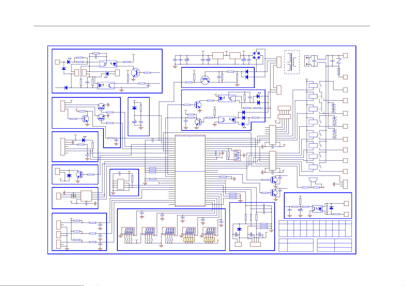
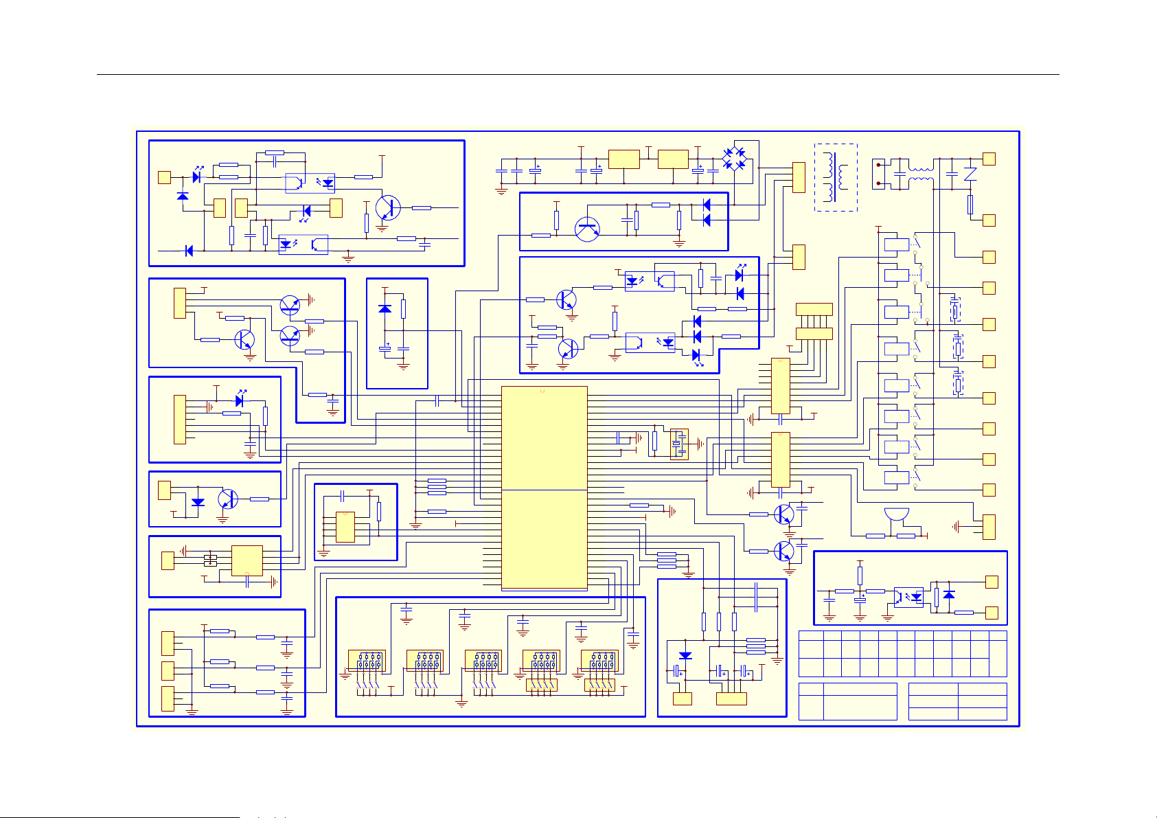
0010451167 PCB information – circuit diagram
XT1
INOUT
2200uF
LED5
2
E1
8.00M
1N4148
1
VDD
R8 10
D17
D1-D4
C34
104
D12
4148
D13
4148
103
C24
R63
LED4
27K
D15
4148
D14
4148
1K
4.7uF
R141KR15
E6
R7 10
R25
4
R13
1K
D16
4148
2.4K
1
2
3
4
5
6
7
8
1
2
3
4
5
6
7
8
4.7K
R27
4.7K
R26
C14 103
C15 103
C16 103
R61 20K
R62 20K
R60 20K
4.7uF
E7
+5
1
CN6
CN20
CN19
VDD
IC1
2003
104
C32
IC2
2003
104
C31
N5
9013
N4
9013
1
4
CN4
1
CN5
A
B
C
12345
12345
16
15
14
13
12
11
10
9
+12
16
15
14
13
12
11
10
9
+12
C35
104
C36
104
T1
TRAN1-2
C20
103
0.1UF/275V
LB1
CN1
C2
+12
RL6
JQ1AP-A
JQ1P-A
JQ1P-A
RL5
JQ1AP-A
RL4
JQ1AP-A
RL3
JQ1AP-A
RL2
JQ1AP-A
RL1
JQ1AP-1
BUZ1
100
R67
+5
R65
200K
R20
1K
2.2uF
4.7K
R35
220
IC8
R9
E8
TLP521-1
J1 J2 J3 J4 J5 J6 J7 J8 J9 J10
0.1UF/275V
RL8
RL7
+12
680
R6
1N4007
D11
C1
FUSE1
100K/1W
187
T3.15A/250V
187
187
187
RC3
0.033uF+120
187
RC1
0.033uF+120
187
RC2
0.033uF+120
187
187
187
187
187
R1
187
1 P2-P6
RV1
1 P1
1 P14
1 P13
1 P12
1 P11
1 P10
1 P9
1 P8
1 P7
CN7
1
1
P16
1
P17
P15
187
D10
1N4007
+5V
GND
CN17
CN16
CN12
CN11
CN15
R43
10K
R39 10K
R22 1K
AB32
+5
CGMXFC
VDDAREF
C33
104
N1 9013
OSC1
OSC2
VSSA
VDDA
VREFH
NOP
AVss
NOP
SW1
+5
470uF/16V
N3
9013
N2
9013
C12
103
E3
R11
R32
4.7K
R33
1K
64
63
62
61
60
59
58
57
56
55
54
53
52
51
50
49
48
47
46
45
44
43
42
41
40
39
38
37
36
35
34
33
103
R5 33K
R2
10K/0.5W
LED3
10K/0.5W
R3
1
CN23
1
2
2.2K
D9
CN14
+12
4
+5
1
R53 10K
+5
CN13
1
7
2
1
D19
4148
+12
DL1
2
DL2
1
+5
+5
1
2
1
1
R4
R54
N8
9013
R19
9013
N10
5
6
7
8
R44
R45
R46
CN22
2
1
C3
1K
103
10K
LED1
R12
560
1K
C6
102
R57
IC4 MAX487
DI4GND
DE
A
/RE
B
RO
VCC
C25 104
10K
R18
10K
R17
10K
R16
C4 103
1
23
R58
N6
N7
4.7K
3
2
1
1K
1K
1K
IC6
TLP371
6
5
1
2
LED2
IC7TLP521
4
9013
4.7K
R28
9013
4.7K
R29
1K
R23
C23
103
C26 104
IC5
1
2
3
4
C17
103
C18
103
C19
103
1
24
CN10
R36
10K
24C01A
EEPROM
RB1
330
R10
+5
+5
4.7K
R30
N9
1K
C8
R21
102
+5
R55
D18
1N4148
10K
E9
C27
104
1uF
C5 102
10K
R51
10K
+5
8
7
6
5
J10
R59
10K
R56
R52
10K
+5v
J7J8J9
10K
R50
+5
C9
103
J5
J6
1/60
CHECK
104E4100uF
C22
C29
R24
1K
4.7K
R31
+5
C7
102
IC3
1
2
IRQ/50Hz
3
RESET
4
NOP
5
6
7
BEEP
8
IR
9
10
11
12
487
13
NET-O
14
NET-I
15
P/G
16
P/G
17
NOP
18
19
20
NOP
21
Vss
22
Vdd
23
SCL
24
SDA
25
26
A
27
B
28
C
29
D
30
31
32
C10
103
RB3RB2 RB5
J4
C11
103
RB4
SW2
J1J2J3
C21
103
+5
330
+5
C28 104
W2
INOUT
7805
TLP741/541
R49
C13
103
+5v
+12
R41
R64
56K
IC10
IC9
TLP521
+5
W1
7812
10K
R34
4.7K
R66
1M
10K
+5
R48 10K
R47 10K
R40 10K
E5
4.7uF
CN8
Page 2
0010451167 PCB information – circuit diagram
通讯线
P15
1
187
D10
1N4007
零线
升降控制
+5V
GND
遥控接收
压机灯
定时灯
电源灯
水泵灯
2
1
CN17
CN16
远程控制
CN12
外部报警门开关浮子开关
CN11
CN15
2
1
1
2
1
1
LED3
R3
D9
CN14
+12
4
1
R53 10K
CN13
1
7
to遥控接收板
D19
4148
+12
DL1
DL2
+5
+5
R2
10K/0.5W
10K/0.5W
CN23
1
2
2.2K
R4
+5
R54
N8
9013
+5
R19
9013
N10
IC4 MAX487
5
6
7
8
10K
R44
10K
R45
10K
R46
R5 33K
C4 103
5
CN22
2
1
C3
1K
1
103
23
R58
9013
N6
10K
9013
N7
LED1
R12
560
1K
C6
102
4.7K
R57
R23
故障输出
DI4GND
3
DE
A
2
/RE
B
1
RO
VCC
C25 104
1K
R18
C17
103
1K
R17
C18
103
1K
R16
C19
103
TLP371
6
LED2
IC7TLP521
IC6
4.7K
R28
4.7K
R29
1K
C23
103
IC5
1
2
3
4
1
24
CN10
1
2
R36
10K
4
C26 104
24C01A
EEPROM电路
RB1
330
R10
+5
+5
8
7
6
5
J10
+5
室内外通讯电路
N9
1K
R21
+5
R55
D18
1N4148
10K
E9
C27
104
1uF
复位电路
R52
10K
+5v
J7J8J9
4.7K
R30
室内外通讯发送
室内外通讯接收
C8
102
C5 102
R51
R59
R56
R50
C9
103
J5
J6
1/60
CHECK
103
104E4100uF
C22
C29
+5
R43
10K
R24
1K
to线控器
4.7K
R31
+5
R39 10K
R22 1K
C7
102
IC3
1
升降门开关
2
IRQ/50Hz
3
RESET
4
NOP
5
升降方向
6
升降电源
7
BEEP
8
IR
9
空
10
电源灯/内故障灯
11
定时灯
12
487使能
13
NET-O
14
10K
10K
10K
10K
+5
步进电机A
步进电机B
步进电机C
步进电机D
无源触点开关
RB3RB2 RB5
NET-I
15
P/G反馈
16
P/G输出
17
NOP
18
线控器输入
19
线控器输出
20
NOP
21
Vss
22
Vdd
23
SCL
24
SDA
25
外部报警输入
26
A
27
B
28
C
29
D
30
高压滤网开关
31
浮子开关
32
无源触点
C10
103
RB4
SW2
J1J2J3
J4
换新风
电加热
CGMXFC
VREFH
水泵/水泵灯
四通/室外通讯输入
外风/室外通讯输出
压机/压机灯
VDDAREF
高压开关
低压开关
内盘管/液管
AB32
C11
103
VDDA
地址1
地址1
选择3
选择2
选择1
+5
470uF/16V
C33
104
N1 9013
N3
9013
N2
9013
低风
中风
高风
OSC1
OSC2
VSSA
健康
加湿
摆风
NOP
AVss
室温
气管
NOP
SW1
+12
IC10
IC9
R64
56K
R41
W1
7812
10K
R34
4.7K
W2
INOUT
7805
E3
C21
103
+5
330
R11
TLP741/541
+5
R32
4.7K
R33
1K
TLP521
64
63
62
61
60
59
58
C28 104
57
56
55
54
53
52
51
50
49
48
47
46
45
44
43
42
41
40
39
38
37
36
35
34
33
+5
室内外通讯发送
室内外通讯接收
R49
R66
1M
10K
+5
R48 10K
R47 10K
R40 10K
传感器
C12
103
C13
103
+5v
E5
4.7uF
CN8
盘管(气)
XT1
INOUT
2200uF
LED5
2
E1
8.00M
1N4148
1
VDD
R8 10
D17
D1-D4
C34
104
D12
4148
D13
4148
103
C24
R63
LED4
27K
D15
4148
D14
4148
1K
4.7uF
R141KR15
E6
R7 10
R25
步进电机D
步进电机C
步进电机B
步进电机A
R13
1K
4
D16
4148
2.4K
1
2
3
4
5
6
7
8
1
2
3
4
5
6
7
8
4.7K
R27
4.7K
R26
C14 103
C15 103
C16 103
R61 20K
R62 20K
R60 20K
4.7uF
+5
E7
1
CN6
CN20
CN19
VDD
IC1
2003
104
C32
IC2
2003
104
C31
N5
9013
N4
9013
室温盘管(液)
1
4
CN4
1
CN5
A
B
C
12345
12345
16
15
14
13
12
11
10
9
+12
16
15
14
13
12
11
10
9
+12
C35
104
T1
TRAN1-2
水泵指示灯
0.1UF/275V
CN1
+12
JQ1AP-A
JQ1P-A
JQ1P-A
JQ1AP-A
JQ1AP-A
JQ1AP-A
JQ1AP-A
JQ1AP-1
LB1
C2
RL6
RL5
RL4
RL3
RL2
RL1
BUZ1
压机指示灯
100
R35
无源触点开关
220
IC8
R9
E8
TLP521-1
有装饰
冷暖
面板
无装饰
单冷
面板
4.7K
负离子
加氧
电脑板型号
C36
104
连接
断开
一拖一
一拖多
无源触点开关
C20
103
R67
+5
R65
200K
R20
1K
2.2uF
J1 J2 J3 J4 J5 J6 J7 J8 J9 J10
有温度
有室
遥控
补偿
室外
无温度
无室
线控
补偿
室外
去掉R58,短接CN22
去掉R4,R5,C3,C4,D9,D10
短接CN23
0.1UF/275V
C1
FUSE1
RL8
RC3
0.033uF+120
RL7
0.033uF+120
+12
1N4007
680
D11
R6
R1
100K/1W
其它机型内机地
一拖一
2P吊落
一拖多
KFR-120Q
专用号
0010451167
版本号 5
零线
187
RV1
T3.15A/250V
187
火线
高风
187
中风
187
低风
187
RC1
0.033uF+120
水泵
187
RC2
摆风
187
加湿
187
健康
187
电加热
187
CN7
换新风
无源火线
187
无源零线
187
址选择
不选择
1 P2-P6
1 P1
1 P14
1 P13
1 P12
1 P11
1 P10
1 P9
1 P8
1 P7
1
1
P16
1
P17
备用
Page 3
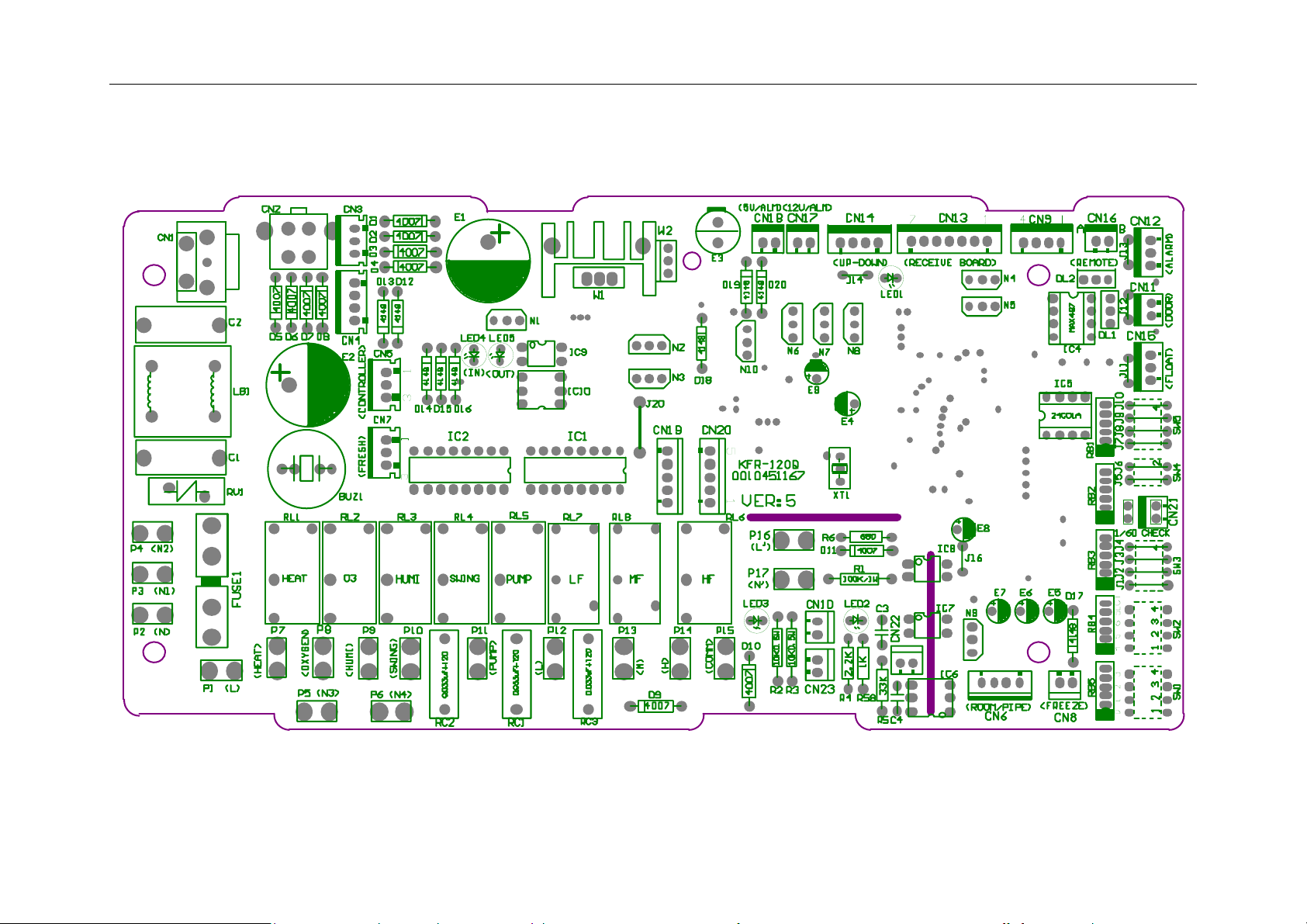
0010451167 PCB information – characters on board(horizontal)
Page 4
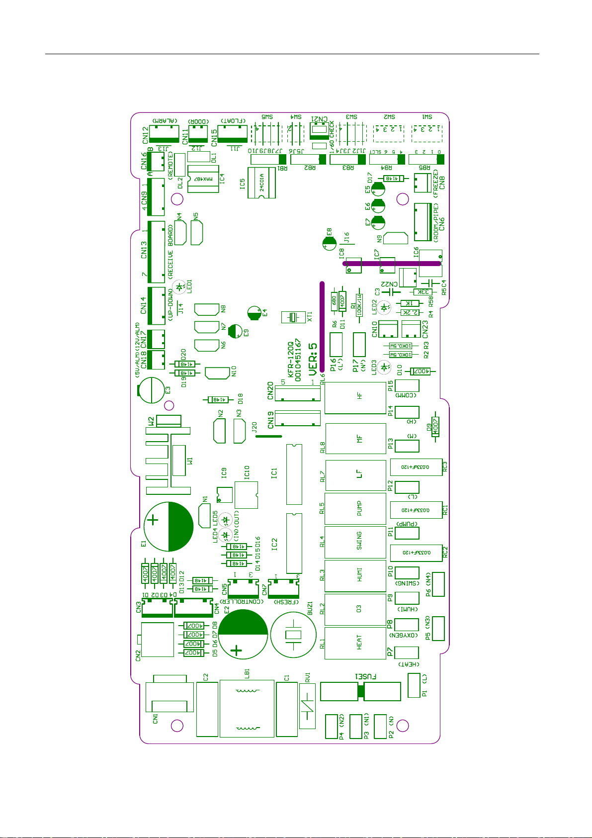
0010451167 characters on board(vertical)
Page 5

Condition for the PCB data:
1.Working ambient temperature:-10℃~70℃, relative humidity:30%~95%
2.Preserved ambient temperature:-20℃~80℃,relative humidity:30%~95%
3.Power supply:220VAC、50/60Hz,voltage range:160V~250V
4.Precise of temperature control:±1℃
0010451167 PCB information – port and definition
P1——connect to external power supply, live line: L (220VAC)
P2——connect to external power supply, neutral line: N (0VAC)
P3、4、5、6——control external load, neutral line: N1、N2、N3、N4(0VAC)
P7——control external load, electrical heat: HEAT (control output 220VAC)
P8——control external load, health function: OXYGEN (control output 220VAC)
P9——control external load, humidification: HUMI (control output 220VAC)
P10——control external load, SWING(control output 220VAC)
P11——control external load, WATER PUMP(control output 220VAC)
P12——control external load, indoor fan motor low speed: L(control output 220VAC)
P13——control external load, indoor fan motor mid speed: M(control output 220VAC)
P14——control external load, indoor fan motor high speed: H(control output 220VAC)
P15——communication with fixed frequency single outdoor unit: COMM(0~220VAC)
P16——input control, signal live line: L’(220VAC)
P17——input control, signal neutral line: N’(0VAC)
CN1——input port of transformer (220VAC)
CN2——input port 1 of transformer (no use)
CN3——input port 2 of transformer (no use)
CN4——input port 3 of transformer (1-2、14VAC,3-4、12VAC)
CN5——input control, connecting port to wired controller: CONTROLLER(three bits: 1. power supply:
12VAC, 2. power supply: 0VAC, 3. communication: COMM.).
CN6——input control, ambient temp.-coil temp. sensor connecting port: ROOM/PIPE(1-2、ROOM,
3-4、PIPE。)
Indoor ambient temp. sensor: R25=23KΩ+-2.5%,B25/50=4200K+-3%,range:(-40,80)
Indoor coil temp. sensor: R25=10KΩ+-3%,B25/50=3700K+-3%,range:(-20,90)
CN7——control external load, fresh air control: FRESH(1. blank, 2. power supply 0VDC, 3. control
output: 12VDC.)
CN8——input signal: FREEZE(no use)
CN9——input control(no use)
CN10——communication with fixed frequency single outdoor unit: (0~12VDC)
CN11——input signal, door switch: DOOR(1-2 short circuit is normal, cut off P8 output)
CN12——input signal, external alarm input: ALARM(1-3 short circuit is normal, if cut off, air
conditioner stops work.)
Note: For convertible type, cassette type, duct type units, CN11 and CN12 must be in short
circuit, or PCB will display failure information.
CN13——input signal, wiring port of remote receiver board: RECEIVE BOARD(1. power supply 5VDC,
2. power supply 0VDC, 3. remote signal, 4. signal output of running lamp 0VDC, 5. signal output of timer
Page 6

lamp 0VDC,6. signal output of power lamp 0VDC, 7. signal output of water pump running lamp 0VDC)
CN14——control external load, auto elevating function (1. signal of door switch close, 2. output of
elevating direction control 0VDC, 3. output of elevating power control 0VDC, 4. power supply 12VDC)
CN15——input signal, detecting water level of float switch (1-3 short circuit is normal, cut off shows
that level exceeds the limitation).If float switch cuts off or occurs other failure, LED1 will flash 10 times.
CN16——input control, wiring port of central controller: REMOTE(1、RS485-B,2、RS485-A。)
CN17——output signal, output signal of failure alarm, control external load, 12V/ALM(1. control output
0VDC, 2. power supply 12VDC)
CN18——output signal (no use)
CN19——control external load, swing 1(1、16VDC,2、0VDC,3、0VDC,4、0VDC,5、0VDC.)
CN20——control external load, swing 2(1、16VDC,2、0VDC,3、0VDC,4、0VDC,5、0VDC.)
CN21——input signal, spring switch, CHECK(1、input signal of earthing, 2. power supply 0VDC)
CN22——short circuit means selecting single split communication type.
CN23——short circuit means selecting multi split communication type.
Page 7

0010451167 PCB information – function selection(ON is 1, OFF is 0)
The standard condition for PCB in factory
SW1:4 bits are OFF
SW2:4 bits are OFF
SW3:4 bits are ON
SW4:2 bits are ON
SW5:4 bits are ON
SW1-SW2: used for indoor unit to set unit address from 1 to 16’
SW3-SW5: used for indoor unit to select different functions.(every dip switches are corresponding to
J1-J10.
SW2-4——logistic relationship of control function(door card control and remote/ wired control)0
means logistic relationship is “and”, 1 means the later coming is preferential.
J1,SW3-1——function selection-control type: 1 means remote control, 0 means wired control.
J2,SW3-2——function selection-temperature compensation in heating mode: 1means “yes”, 0means
“no”.
J3,SW3-3——function selection-outdoor communication: 1means “yes”, 0means “no”. This PCB
must be 1.
J4,SW3-4——function selection-heat pump unit: 1means “heat pump”, 0means “cooling only”.
1/60——test in short circuit, but in operation short circuit mustn’t be permitted.
CHECK——short spring switch control, it also can be used as switch of convertible type except for
testing.
J5,SW4-1——function selection-elevating function: 1means “yes”, 0means “no”.
J6,SW4-2——function selection –health function: 1means common (indoor fan motor running); 0
means special (indoor, outdoor running).
J7,SW5-1——function selection –swing mode: 1 means common(simultaneous motor), 0 means
special (swing motor).
J8,SW5-2——function selection – system combination: 1means fixed frequency single unit, 0 means
fixed frequency multi split.
J9,SW5-3——function selection –group control: 1 stands for the master unit (its address in wired
controller is 0), 0 stands for the slave units (the address should be set by the dip switch, their addresses
only can be in the range: 1~15)
J10,SW5-4——function selection –preset: 1 no meaning, 0 no meaning
Page 8

0010451167 PCB information- control type
Control type selection between remote and wired: select by dip switch J1, SW3-1(1 means remote control;
0means wired control).
For remote control type, please use remote controller YR-H71, and a remote receiver is equipped with
indoor unit. For wired control type, wired controller YR-E12 will be used, 3-core shied wire is equipped with
indoor unit.
Door card control: controls ON/OFF, the start up setting will comply with last time request memorized
according to condition memorize function. Its difference with emergency switch of convertible type unit lies:
the emergency switch control will perform in the condition: 24degrees, auto fan speed in auto mode.
The function combination between door card and remote/wired control type: select by dip switch: SW2-4(0
means “and”, 1 means later coming is preferential.)
Dip switch position in wired control type: Only one indoor unit of all indoor units connected with wired
controller is the master unit, whose address is 0, function selection switch(J9,SW5-3)is 1. The others are
slave units, and the quantity can be 0~15, whose addresses are(SW1:1~4)from 1 ~15, and cannot
repeat.
Wiring request in wired control type: the wired controller ports A-B-C are connected with indoor port CN5
(1-2-3) through 3-core shield wire. Requirements:
1. Port A only connects with either of indoor port CN5(1)
2. Port B connects with port CN5 (2) of all indoor units.
3. Port C connects with port CN5 (3) of all indoor units.
Dip switch position in central control type: the addresses (SW1:1~4;SW2:1~4)of indoor units connected
with central controller can not repeat. In principle, they should be in the order from small to big.
Wiring request in central control type: port A-B is connected with indoor port CN16(A-B)through 2-core
shield wire. Requirements:
1. Port A connects with port CN16(A)of all indoor units.
2. Port B connects with port CN16(B)of all indoor units.
When only use remote control type, please select remote control unit, and install according to installation
manual, there is no other special request.
When only use wired control type, please select wired control unit, and install according to installation
manual. When control multi indoor units, take care the requirements of dip switch and wiring, there is no
other special request.
When only use central control type, please firstly install according to air conditioner requests and set the
dipswitch, there is no other special request.
When central control type(128×)and remote control type are used simultaneously, set the dip switch
according to central control type, there is no other special request.
When central control type(128×)and wired control type (16×)are used simultaneously, max. indoor
Page 9

units sets: 128×16 can be controller. Address setting of central controller can be met firstly, and then
modulate the address setting of slave unit wired controlled.
LED in indoor PCB:
1. LED1:is the state lamp for remote receiver as well as failure lamp. If indoor unit is normal, LED1 is on,
or if failure occurs, LED1 flashes regularly, and you can adjust failure type according to the flash times.
2. LED2:is used for multi split units as communication lamp. If communication between indoor and
outdoor is normal, LED2 will be on.
3. LED3:is used for single split units as communication lamp. If communication between indoor and
outdoor is normal, LED3 will be on.
4. LED4、LED5:is the lamp that shows the data receiving or sending between wired controller and PCB,
If LED4、LED5 be on in turn, communication between wired controller and PCB is normal.
Page 10

10. Diagnostic information
10.1 Failure code
remote control type unit:
failure description
indoor ambient temp. sensor failure
indoor coil temp.sensor failure
outdoor ambient temp. sensor failure
or 4-way valve broken down in heating mode
outdoor coil temp. sensor failure
over-current protection failure or phase sequence fault
refrigerant system pressure too high or low
communication between indoor PCB and receiver panel failure
communication between indoor PCB and outdoor PCB
drainage failure
Note: For convertible type unit, drainage failure is not available.
Wired control type unit failure code:for old wired controller
Failure description Failure code on wired
controller
Indoor ambient temp. sensor abnormal E1
Indoor coil temp. sensor abnormal E2
Outdoor ambient temp. sensor abnormal E3
Outdoor coil temp. sensor abnormal E4
Over current protection E5
Over high or low pressure protection E6
Communication between panel and indoor
E8
abnormal
Communication between indoor and outdoor
E9
abnormal
Water pump failure E0
indoor running
lamp flash times
1
2
3
4
5
6
8
9
10
Page 11

Failure code with wired controller YR-E12:
For
remote
type, flash
times
10 08 21 Drainage system failure Float switch broken down for more than
1 01 01 Indoor ambient temp. sensor
2 02 02 Indoor coil temp. sensor failure sensor broken down or short circuit for
3 4A 11 Outdoor ambient temp. sensor
4 49 12 Outdoor coil temp. sensor
5 48 10 Over-current protection CT check abnormal 3 times in 30m
6 53 14 High pressure abnormal High pressure switch acts 3 times in 30m
8 07 06 Communication between wired
9 06 05 Communication between
11 0B 30 Outside alarm signal input Outside signal broken down for more than
12 03 20 Gas pipe temp. sensor
13 0D 31 Solenoid valve abnormal Solenoid valve act incorrectly 3 times
15 05 17 EEPROM abnormal EEPROM data missing
Failure
code on
wired
controller
For central
control,
failure code
Failure description Reason
25m continuously
sensor broken down or short circuit for
failure
failure
failure (compressor
discharging temp. sensor)
controller and indoor abnormal
indoor and outdoor abnormal
abnormal
more than 2m continuously
more than 2m continuously
sensor broken down or short circuit for
more than 2m continuously
Sensor broken down or short circuit for
more than 2m continuously
Communication abnormal for more than
4m continuously
Communication abnormal for more than
4m continuously
10s
Sensor broken down or short circuit for
more than 2m continuously
continuously
Page 12

8.2 Trouble Shooting - Detailed for engineer
Plug the supply coil properly
Return to the controller manufacturer for
repair
The power supply coil isn’t plugged
well
Damaged fuse Replace with a good one
Damaged wave filtering component
Return to the controller manufacturer for
Plug the transformer well or replace with a
The transformer isn’t plugged well or
repair
good one
is damaged
Damaged component on power
supply unit of indoor board
Return to the controller manufacturer for
repair
Replace with a good connection cable
Damaged major chip
Damaged connection cable between
Connect the cable well
board and indoor board isn’t
connected well
Connection cable between display
display board and indoor board
Damaged reception adaptor Replace with a good one
Return to the controller manufacturer for
repair
Damaged remote circuit or major chip
Return to the controller manufacturer for
repair
Damaged major chip
Damaged dynatron Q1 Replace with a good one
Damaged buzzer Replace with a good one
Connect connection parts well
Replace with a good 2803
well with connection cable
CN8 on indoor board is not plugged
Damaged 2803
Damaged 2803 Replace with a good 2803
Damaged relay JK1 Replace with a good one
Damaged relay JK2 Replace with a good one
Unavailable voltage at input part of
circuit board
Unavailable voltage at one end of
the fuse
consequent pole of transformer
Unavailable output from the
Trouble Checkup result Possible reasons Corresponding solution
No response after
power being
connected
chip
Improper output of 7805
Normal power supply for major
Indicator lamps do not light
Display board does
not make normal
response
Remote control cannot be received
wo ends of the buzzer
Unavailable square wave signal at
t
The buzzer does
not beep while
making remote
No output from 2803 on indoor
Available square signal at two
control
board
ends of the buzzer
Normal output of relays K1, JK2,
JK3
Indoor blowing fan
does not run
No output at 16 pin of 2803 on
JK2 on indoor board
of relay
No output at relay JK1 on indoor
indoor board
Unavailable voltage on COM port
Indoor blowing fan
cannot not
board
generate low wind
Page 13

Replace with a good 2803
Replace with a good 2803
Press sleep button 10 times within 5
seconds (and the buzzer will beep 4 times),
the system is then set to power breakdown
memory mode.
Return to the controller manufacturer for
repair
Plug CN4 well with the connection cable
Plug CN6 and the connection cable well
Socket CN4 is not plugged well with
Damaged relay JK3 Replace with a good JK3e
No output at 15 pin of 2803 Damaged 2803
No voltage at COM of relay JK3 on
Damaged relay JK2 Replace with a good JK2
oor board
ind
No output at relay JK2 on indoor
board
Damaged relay JK3 Replace with a good JK3
No output at 14 pin of 2803 Damaged 2803
board
No output at relay JK3 on indoor
Damaged relay JK6 Replace with a good JK6
No output at 11 pin of 2803 Damaged 2803 Replace with a good 2803
board
No output at relay JK6 of indoor
Damaged relay JK7 Replace with a good JK7
Socket CN6 is not plugged well with
d
output of relay JK7 on indoor
No output at 18 pin of 2803 Damaged 2803 Replace with a good 2803
No
No setting has been made
Damaged chip IC6 of indoor board
boar
Available output of relay JK7 on
connection cable
indoor board
Damaged relay JK5 on indoor board Replace with a good JK5
No output of relay JK5 on indoor
board
No output at 12 pin of 2803 Damaged 2803 Replace with a good 2803
connection cable
Available output of relay JK5 on
indoor board
Trouble Checkup result Possible reasons Corresponding solution
No swing wind
No output of
four-way valve
during heating
Indoor blowing fan
cannot generate
medium wind
Indoor blowing fan
cannot generate
high wind
No output of swing
Unavailable power
breakdown memory
Unavailable power
breakdown memory
program
under swing mode
Page 14

It will restore automatically when
the temperature of indoor coil pipe
after three minutes
The compressor will work normal
rises to 7
Too low temperature of indoor coil pipe
causes overcooling protection
Damaged 2803 Replace with a good 2803
Plug the connection cable well
Connection cable between the compressor
Damaged relay JK6 on indoor board Replace with a good JK6
it
It will restore normally after 3
It will automatically restore when
the temperature of indoor coil pipe
falls to 57
and JK6 isn’t plugged well
Too high temperature of indoor coil pipe
causes overheat protection
Plug the connection cable well
Damaged 2803 Replace with a good 2803
Damaged relay JK6 on indoor board Replace with a good JK6
Connection cable between compressor
Damaged Q2 Replace with a good Q2
and JK6 isn’t plugged well
Plug the connection cable well
Socket CN6 is not plugged well with
Damaged relay JK8 on indoor board Replace with a good JK8
connection cable
or board
Three minutes’ protection for compressor
No output at 11 pin of 2803 on
indo
Trouble Checkup result Possible reasons Corresponding solution
During cooling program,
the compressor does not
start when the
temperature meets
No output of relay JK6 on indoor
board
board
3 minutes’ delay protection for compressor
During heating program,
No output of relay JK6 on indoor
proper conditions
No output at 11 pin of 2803 of
the compressor does not
start when the
indoor board
temperature meet proper
conditions
No output of relay JK6 on indoor
board
Available output of relay JK6 on
indoor board
During heating program,
the compressor does not
start when the
temperature meet proper
conditions
Available output of relays on
No output of relay JK8 on indoor
No output at collector of Q2 on
indoor board
board
During cooling program,
the compressor works
while outdoor blowing
indoor board
fan does not
Page 15

It will automatically restore when
the temperature of indoor coil
pipe falls to 57
Too high temperature of indoor coil pipe
causes overheat protection
Damaged Q2 Replace with a good Q2
Plug the connection cable well
Socket CN6 is not plugged well with
Damaged relay JK8 on indoor board Replace with a good JK8
Return to the controller
manufacturer for repair
connection cable
Damaged rectification diode D6-D7 etc.
Damaged transformer CT1 Replace with a good one
Return to the controller
manufacturer for repair
Replace with a good one
Damaged temperature sensor for indoor
coil pipe
Damaged 2803 Replace with a good 2803
Plug the connection cable well
Damaged relay JK4 on indoor board Replace with a good JK4
Socket CN5 is not plugged well with
Replace with a good one
Faulty connection cable to transmit float
feedback signal
connection cable
No output at collector of Q2 on
indoor board
Trouble Checkup result Possible reasons Corresponding solution
During heating program,
the compressor work while
outdoor blowing fan does
not
During heating program,
No output of relay JK8 on indoor
board
the compressor work while
Available output of relays on
indoor board
Current transformer outputs
normally
outdoor blowing fan does
not
ormally
Transformer CT1outputs
abn
Inaccurate protection current Adjust the adjustable potentiometer
Abnormal overcurrent
detection
Damaged major chip
Damaged indoor temperature sensor Replace with a good one
With timing indicator and
compressor indicator
extinguishing, the
With timing indicator and
operation indicator flashes
compressor indicator
every second
lighting, the operation
indicator flashes every
second
o output of relay JK6 on indoor
No output at 13 pin of 2803 on
oard
indoor board
N
b
Water pump indicator
flashes every second
indoor board
Available output of relay JK6 on
(trouble for water
discharging)
 Loading...