

Page 1

MKII
GB
Wireless Speedlight
for Fujilm
Modus 600RT 1
Instruction
Manual
Page 2

GB
2 Modus 600RT
Page 3

Foreword
Thank you for purchasing the hähnel Modus
600RT.
The Modus 600RT is a speedlight for Fujilm
DSLR series cameras and is compatible with the
TTL Auto ash system.
• Before starting to shoot, be sure to read this
manual
• When reading this manual also refer to the
camera’s Instruction Manual
Conventions &
assumptions
• The manual is based on the assumption that all
devices including the camera are switched on
• Reference page numbers are indicated by
(page **)
The caution symbol indicates a warning to
•
prevent shooting problems
The Note symbol gives supplemental
•
information
GB
Modus 600RT 3
Page 4

Contents
GB
1 Introduction
• Safety precaution - Warnings & Cautions
• Nomenclature
• Body
• Control Panel
• LCD Panel in ve modes
• Viper TTL Transmitter
2 Getting started
• What’s in the Modus 600RT? 14
• What’s in the Modus 600RT Wireless Kit?
• Battery and charger
• Attaching to camera
• Power Management
• Flash Mode - TTL Autoash
• FEC (Flash Exposure Compensation)
• FEB (Flash Exposure Bracketing)
• FV Lock (Flash Value Lock)
• HSS (High Speed Sync)
• 2nd Curtain Sync
• Flash Mode - Manual Flash
• Flash output power range
• Optical O1 Secondary unit setting
• Optical O2 Secondary unit setting
• Flash Mode - MULTI: Stroboscopic Flash
• Calcualting the shutter speed
• Number of ashes / ash frequency
= shutter speed
3 Wireless Flash Photography: (2.4GHz)
Control
• Master/Slave wireless ash lighting 2
• Wireless multiple ash shooting
• Wireless settings
• Master unit Setting
• Slave unit Setting
• Master unit ash ON/OFF
• Setting the group mode: TTL / M / off
• DCM (Digital channel matching)
• Master - Viper TTL or Modus 600RT
• Slave - Modus 600RT
• Modus 600RT Reset
• TTL - Fully automatic wireless
ash shooting
• Using Automatic wireless ash with multiple
slave units
• Adavnced setting with fully automatic
wireless ash
• Multiple master unit
• M: Wireless Flash Shooting with
Manual Flash
• MULTI: Wireless Flash Shooting with
repeating ash stroboscopic
Page
6
8
9
11
12
14
14
17
17
18
19
19
19
20
20
21
21
21
21
22
22
4
25
26
26
26
26
27
27
27
28
28
30
30
31
31
31
4 Modus 600RT
Page 5

Page
• M/A/B/C: Wireless ash shooting with different
ash modes for each goup
4 Wireless Flash Photography: Optical
Transmission
• Optical O1 Secondary unit setting
• Optical O2 Secondary unit setting
5 Wireless Flash Photography: (2.4GHz) using
Viper TTL Transmitter
• Wireless setting
• DCM (Digital Channel Matching)
• Viper TTL group Mode Setting
Group Power Control setting for Manual
•
and TTL FEC 36
• Multi Mode
6 Other Applications
• Sync Triggering 38
• Auto Focus Asist Beam
• Bounce Flash
• Catchlight Panel
• Zoom – Setting the Flash Coverage and using
Wide Panel
• C.Fn – Setting Custom Functions
• Protection Functions
• Technical Data
• Troubleshooting
• Firmware Upgrade
• Maintenance
GB
32
34
34
36
36
36
37
38
38
39
39
40
41
43
44
45
45
Modus 600RT 5
Page 6

GB
Introduction
1
Warnings:
Failure to observe the instructions below may
result in loss of life or serious bodily injury. To
prevent re, excessive heat, chemical leakage,
explosions, and electrical shock, follow the
safeguards below:
• Do not insert any foreign metallic objects
into the electrical contacts of the product,
accessories, connecting cables, etc
• Do not use any batteries, power sources, or
accessories not specied in the instruction
manual. Do not use any deformed or modied
batteries, or the product if it is damaged
• Do not short-circuit, disassemble, or modify
the product or batteries. Do not apply heat or
solder to the batteries. Do not store batteries
with metal objects. Do not expose the batteries
to re or water. Do not subject the batteries to
strong impact or continuous mechanical shock
• Do not place batteries in a microwave, cooker
or high-pressure container
• Do not use the product in locations where there
is ammable gas
• Do not re the ash at anyone driving a car or
other vehicle
• Do not disassemble or modify the equipment.
High-voltage internal parts may cause electrical
shock. If you drop the equipment and the
casing breaks open to expose the internal
parts, do not touch the exposed parts. There is
a possibility of an electrical shock
• Do not store the product in dusty or humid
places or locations with lots of oil smoke. Do
not store the battery in a charger
• Keep the batteries and other accessories out of
the reach of children and infants
• Do not drop the product or battery into re or
water
• Do not expose the product or battery to
excessive temperature (below 0ºC or above
40ºC) or strong direct sunlight
6 Modus 600RT
Page 7

• Battery temperature while on charge or in use
should never increase above 60ºC/140ºF. If
higher temperature occurs, stop using and stop
charging immediately
• Do not use paint thinner, benzene, or other
organic solvents to clean the product
Caution:
• Failure to observe the instructions below may
result in serious bodily injury or damage to
property
• When the product is not in use for a prolonged
period, make sure to remove the batteries
before storing
• When disposing of a battery, insulate the
electrical contacts with tape. Contact with
other metallic objects or batteries may cause
a re or an explosion. Dispose of batteries
in accordance with the appropriate local
regulations
• Do not store or leave the product or battery
in the trunk, or on the dashboard of a vehicle
or in direct sunlight or with a high interior
temperature as overheating can result in burns
if touched, leaking, re or explosion
• Do not re the ash with the ash head (lightemitting unit) in contact with a human body or
any object as doing so may result in the risk of
burns and re
• Do not re the ash near the eyes. Keep the
ash unit at least 1m (3.3 feet) away from
face. It may hurt or damage the eyes. Using
bounce ash to reduce light intensity is also
recommended
GB
Modus 600RT 7
Page 8

Nomenclature
GB
01
02
03
04
05
06
10
07
08
09
11
12
Nomenclature - Body
01. Catchlight Panel
02. Built-in Wide Panel
03. Flash Head
04. Optical Control Sensor
05. Focus Assist Beam
06. Slave Flash Ready Indicators
8 Modus 600RT
07. Sync Cord Jack
08. USB Port
09. Hotshoe
10. Dot-matrix LCD Panel
11. Battery Compartment
12. Quick Lock
Page 9
Nomenclature - Control Panel
13 18
14
15
16
17
GB
19
20
21
22
13. Function Button 2
14. Function Button 1
15. <
> Mode Selection
Button / Lock button
16. <
> Test Button / Flash
Ready Indicator
18. Function Button 3
19. Function Button 4
20. <
> Wireless Mode/
Master/Slave
21. ON/OFF Power Switch
22. Select Dial
17. <SET> Set Button
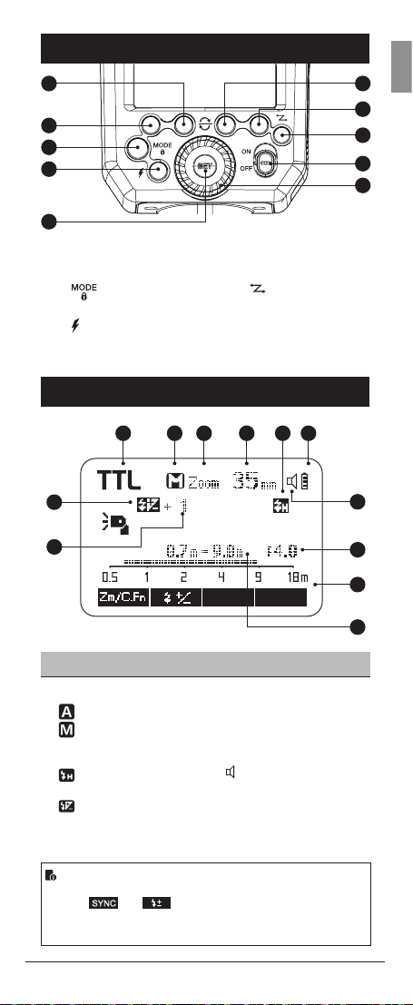
Nomenclature - LCD Panel
01 02 03 04 05 06
07
08
(1) TTL Autoash
01. TTL: TTL autoash
02. : Automatic
: Manual
03. Zoom: zoom display
04. Focus Distance
: High-speed sync
05.
06. Battery level indicator
07. : Flash exposure
compensation
08. Flash exposure
compensation amount
09. Aperture
10. Distance indicator scale
11. Effective ash range
12.
Beep on/off (C. Fn 7)
12
09
10
11
• The display will only show the settings currently applied.
• The functions displayed above function buttons 1 to 4, such
• When a button or dial is operated, the LCD panel is
Modus 600RT 9
as
illuminated.
and
change according to settings’ status.
Page 10
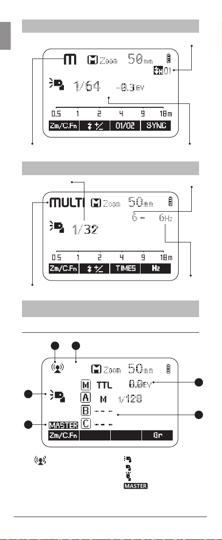
(2) Manual Flash
GB
M : Manual ash Manual ash output power
O1: Standard Optical. 02: Preash Optical
(3) Multi: Multi Stroboscopic Flash
Flash power Number of ashes
MULTI : Multi Stroboscopic Flash
Flash
frequency
(4) Radio Control Shooting
(a) Master Unit - Flash Mode
15
16
19
17
20
18
:Master unit ash ON
15. : Radio control
wireless shooting
16. Flash mode : <blank>,
<MULTI>
10 Modus 600RT
17.
:Master unit ash OFF
:Master unit bounce ON
18. : Master
19. Master Group: Mode
20. A.B/C Group: Mode
Page 11
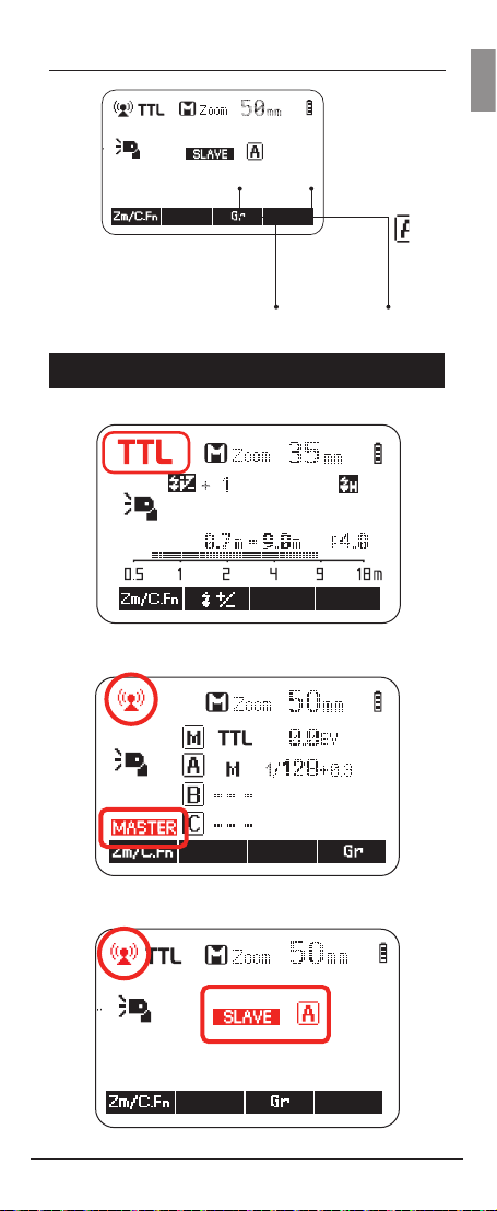
(b) Slave Unit
Slave mode Group A/B/C...
LCD Panel in three Modes
(1) Attached to the Camera
(2) 2.4GHz Radio Control: As a Master Unit
GB
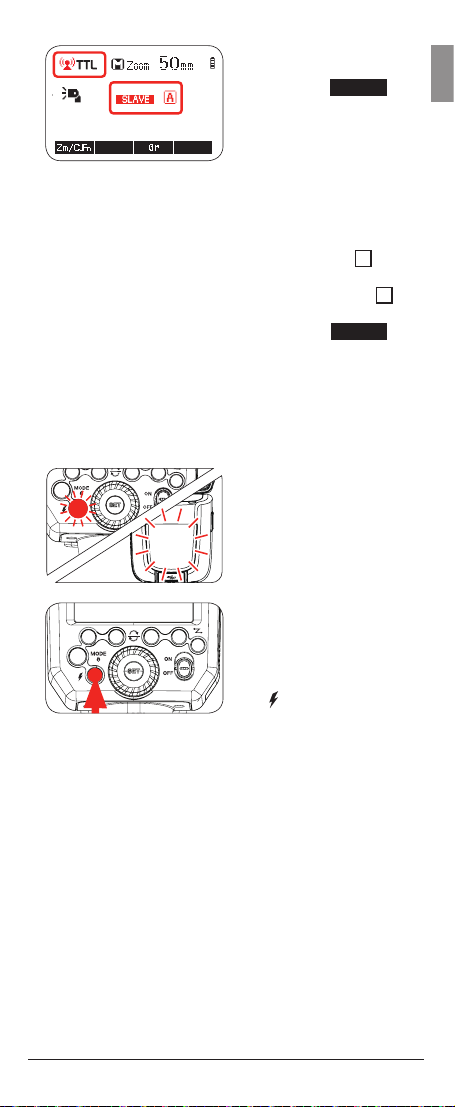
(3) 2.4GHz Radio Control: As a Slave Unit Group A
Modus 600RT 11
Page 12

Nomenclature - Viper TTL
GB
Transmitter
08
09
07
06
A B C
01
02
05
(A) Group A
(B) Group B
(C) Group C
(1) ON/OFF - switch
(2) SEL - select button
(3) Adjust Dial - To adjust
settings
Transmitter LCD Screen
04
(4) Lock Wheel
(5) LCD Screen
(6) Power / Status LED
(7) Hot shoe
(8) Test - button
(9) Micro USB - rmware
update
10
16
1211
03
13
14
15
12 Modus 600RT
Page 13
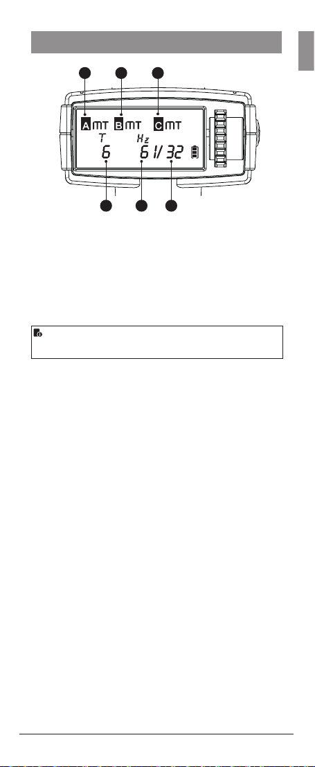
Multi Mode
GB
B CA
191817
(10) Manual / TTL / OFF Mode
(11) Flash exposure
compensation amount
(12) Manual ash output
(13) High-speed sync
(15) Always On
(16) Battery indicator
(17) Number of ashes
(18) Flash frequency
(19) Flash output power
(14) Rear curtain sync
• The Viper transmitter is included in the “Modus 600RT
Wireless Kit”
Modus 600RT 13
Page 14

GB
Getting Started
2
What’s in the Modus 600RT?
1. Modus 600RT
Speedlight
2. Li-ion Battery Pack
3. Battery Charger
4. Micro USB Cable
5. Mini Stand
6. Protection Case
7. Instruction Manual
What’s in the Modus 600RT
Wireless Kit?
1. Modus 600RT
Speedlight
2. Viper TTL Transmitter
3. Li-ion Battery Pack
4. Battery Charger
5. Micro USB Cable
6. Mini Stand
7. Protection Case
8. Instruction Manual
9. 2 x AA Batteries
Battery and Charger
• The HLX-MD1 battery must be charged before use.
• Use the supplied MD1 MKII charger to charge the
battery.
• Remove battery from charger when charging is nished
and disconnect charger from mains
A fully charged battery will offer approx 500 ashes at full
power and even more when power level is reduced. The
composition and construction of the MD1 battery pack
offers very reliable and fast refresh time for the speedlight.
How to store the battery
When not in use remove the battery from the charger
or the speedlight and store the battery in a cool and
dry place. Exposing the battery to higher temperatures
can shorten the lifetime of the battery. Store the battery
almost empty (one bar in the battery level indicator) when
not used for a long period of time. For optimum battery
life, use battery regularly and if not used for more than 6
months, charge the battery fully and use it with the Modus
600RT until the battery level is down to 1 bar again before
storage.
Battery Lifetime
The lifetime of a recharable battery is limited. The capacity
will drop progressively with use and the age of the battery
pack. Replace the battery pack when the ash cycle
time becomes longer or the number of ashes reduces
noticeably. The battery lifetime can vary substantially
depending on storage, operation conditions and exposure
to unsuitable enviormental conditions
14 Modus 600RT
Page 15

Caution
• Do not short circuit the battery
• Do not drop the battery into water or re
• Do not drop or dismantle or subject the batteries to
strong impact or continuous mechanical shock
• Stop using the battery if the battery has any signs
of damage or bulging the to housing and dispose of
the battery in accordance with the appropriate local
regulations
How to charge the battery
The HLX-MD1 battery must be charged before use.
Use the supplied MD1 MKII charger to charge the
battery. Connect the MD1 MKII charger to a USB
adapter (min 5V 2 Amp) with the supplied Micro
USB Cable . To start the charge insert the HLX-MD1
battery into the MD1 MKII charger and the green
LED bars will illuminate, indicating that the battery
is charging. 4 green LED’s on indicates full charge.
Remove the battery from charger when fully charged.
GB
Modus 600RT 15
Page 16

Fitting and Removing the Battery
GB
1. To t the battery,
push the battery
compartment cover
downward and open it.
2. According to the
triangle sign on the
battery pack, insert it
into the compartment
until a white clip locks
the battery with a click
sound.
3. To remove the battery,
tap the white clip and
the battery pack will
pop out. Then close the
compartment.
Battery Level Indication
Make sure the battery pack is securely tted in the ash.
Check the battery level indication on the LCD panel to see
the remaining battery level.
Low Battery Warning
Battery Level
Indication
3 bars
2 bars
1 bar
No bars
Blinking
16 Modus 600RT
Meaning
Full
Middle
Low
Lower battery, please recharge it
The battery level is going to be
used out immediately.
Note: Please recharge the battery
as soon as possible (within 10
days). Then, the battery can be
used or stored as detailed in the
“How to store the battery” section.
Page 17
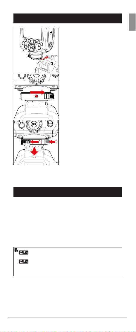
Attaching to Camera
a
b
c
GB
1. Attach the Speedlight
to the camera.
Slip the ash’s mounting foot
into the camera’s hotshoe all
the way.
2. Secure the Speedlight Push
the release button to rotate
the lock ring on the mounting
foot until it locks in position
to the right.
3. Detach the Speedlight:
a) Push the release button.
b) Rotate the lock ring to
the left until it is loosened.
c) Slide the speedlight off the
camera hotshoe
Power Management
Use the ON/OFF Power Switch to power the ash unit
on or off. Switch off if it will not be used for an extended
period of time. Set as a master ash, it will turn the
power off automatically after a certain period (approx. 90
seconds) of idle use. Pressing the camera shutter halfway
or pressing any ash button will wake up the ash unit.
Set as a slave ash, it will enter sleep mode after a certain
period (adjustable, 60 minutes by default) of idle use.
Pressing any ash button will wake it up.
Disabling Auto Power Off function is recommended
when the ash is used off camera. (C.Fn-APO)
Slave Auto Power Off Timer is set to 60 minutes by
default. Another option “30 minutes” is available. (C.Fn-
Sv APOT, Page 42)
Modus 600RT 17
Page 18

Flash Mode - TTL Autoash
GB
This ash has three ash modes: TTL, Manual (M), and
MULTI (Stroboscopic). In TTL mode, the camera and the
ash will work together to calculate the correct exposure
for the subject and the background. In this mode, multiple
TTL functions are available: FEC, HSS & second curtain
sync, modeling ash. These can be controlled with the
Modus 600RT or with the camera’s menu screen.
* Press < MODE > Mode Selection Button and three ash modes
will display on the LCD panel one by one with each pressing.
TTL Mode
Press < MODE > Mode Selection Button to enter TTL
mode. The LCD panel will display TTL.
• Press the camera release button halfway to focus. The
aperture and effective ash range will be displayed in
the LCD panel.
• When the shutter button is fully pressed, the ash will
re a preash which the camera will use to calculate the
correct ash output power the instant before the photo
is taken.
FEC: Flash Exposure Compensation
With FEC function, you can adjust the calculated level
from -3 to +3 in 1/3 stops. It is useful in situations where
minor adjusting of the TTL system is needed based on the
lighting environment.
Setting FEC:
1. Press Function Button
2 <
icon <
exposure compensation
amount will be
highlighted on the LCD
panel.
18 Modus 600RT
>. The
> and ash
Page 19
SET
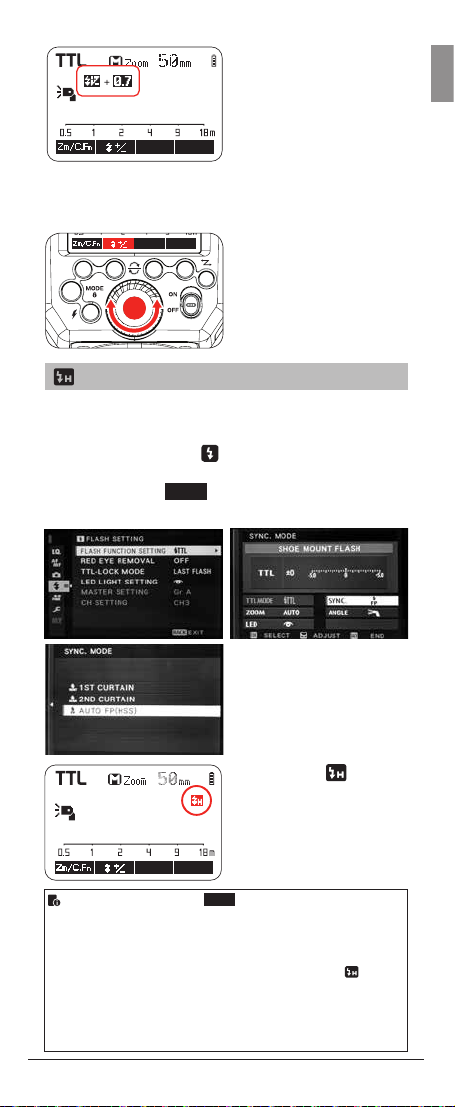
2. Set the ash exposure
compensation amount.
• Turn the Select Dial to
set the amount.
• “0.3”means 1/3 step,
“0.7”means 2/3 step.
• To cancel the
ash exposure
compensation, set the
amount to “+0”.
3. Press < SET > button
again to conrm the
setting.
High-Speed Sync
High Speed Sync FB (HSS) enables the ash to
synchronize with all camera shutter speeds. This is
convenient when you want to use aperture priority for llash portraits. Use the <
menu to adjust the setting of the ash light. Choose Auto
FB (HSS) on the <
high-speed sync function.
> ash setting on the camera
SYNC
> setting which activates the
GB
1. The icon <
displayed. If camera
> will be
(Auto FP) is enabled.
HSS is now turned on
• Choose < FP > on the <
high speed sync function.
• With high-speed sync, the faster the shutter speed, the
shorter the effective range
• To return to normal ash, set the camera ash sync speed
to other option other than Auto FP. Then the icon < > will
no longer be shown
• MULTI mode cannot be set in high-speed sync mode
• Over-temperature protection may be activated after 15
consecutive high-speed ashes
Modus 600RT 19
SYNC
> setting will activate the
Page 20
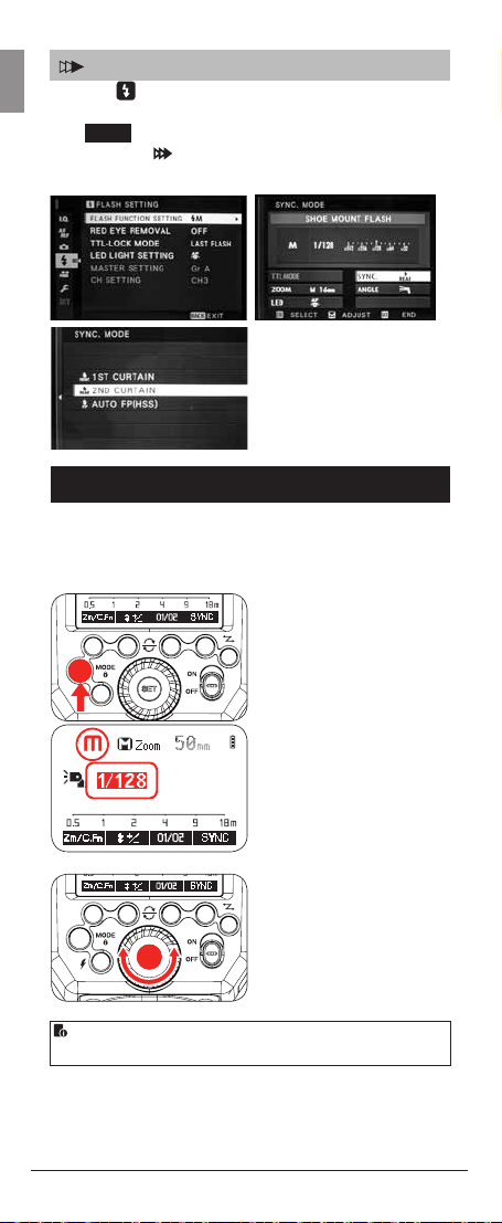
Second-Curtain Sync
SET
GB
Use the < > ash setting on the camera menu to adjust
the setting of the ash light. Choose <2nd Curtain> on
SYNC
the <
sync. The icon
enabled
> setting which activates the Second curtain
will be displayed when 2nd curtain sync
Flash Mode - Manual Flash
The ash output is adjustable from 1/1 full power to
1/128th power in 1/3rd stop increments. To obtain a
correct ash exposure, use a hand-held ash meter to
determine the required ash output.
1. Press < MODE >
button so that < M > is
displayed
2. Turn the Select Dial to
choose a desired ash
output amount
3. Press < SET > button
again to conrm the
setting
• High Speed Sync and 2nd curtain sync can be selected in
< M > mode, using the camera menu.
20 Modus 600RT
Page 21
Flash Output Power Range
The following table makes it easier to see how the stop
changes in terms of f/stop when you increase or decrease
the ash output.
For example, when you decrease the ash output: 1/2,
1/2-0.3, or 1/2-0.7, or increase the ash output:1/2,
1/2+0.3, 1/2+0.7, 1/1.
Figures displayed when reducing ash output level→
1/1-0.3 1/2-0.3 ------1/1-0.7 1/2-0.7
1/1 1/2 1/4
1/2+0.7 1/4+0.7 ------1/2+0.3 1/4+0.3
←Figures displayed when increasing ash output level
Optical O1 Secondary Unit Setting
In M manual ash mode, press <O1/O2> button so that
this ash can function as an optical O1 secondary ash
using its optical sensor. With this function, the ash will
re synchronously when a second main ash res. This is
the same effect as usng a radio trigger to re the ash off
camera. This helps create multiple lighting effects.
Optical O2 Secondary Unit Setting
In M manual ash mode, press <O1/O2> button so that
this ash can function as an optical O2 secondary ash
using its optical sensor. With this function, the ash will
re synchronously when a second main ash res as in
O1 but it will ignore the metering pre-ash and re only in
response to the exposure ash from the main unit.
GB
• O1 and O2 optic triggering is only available in M manual
ash mode when the Modus 600 RT is off camera
• Press function button 4 <
when in 01/02 mode
SYNC
> to activate the “HSS”
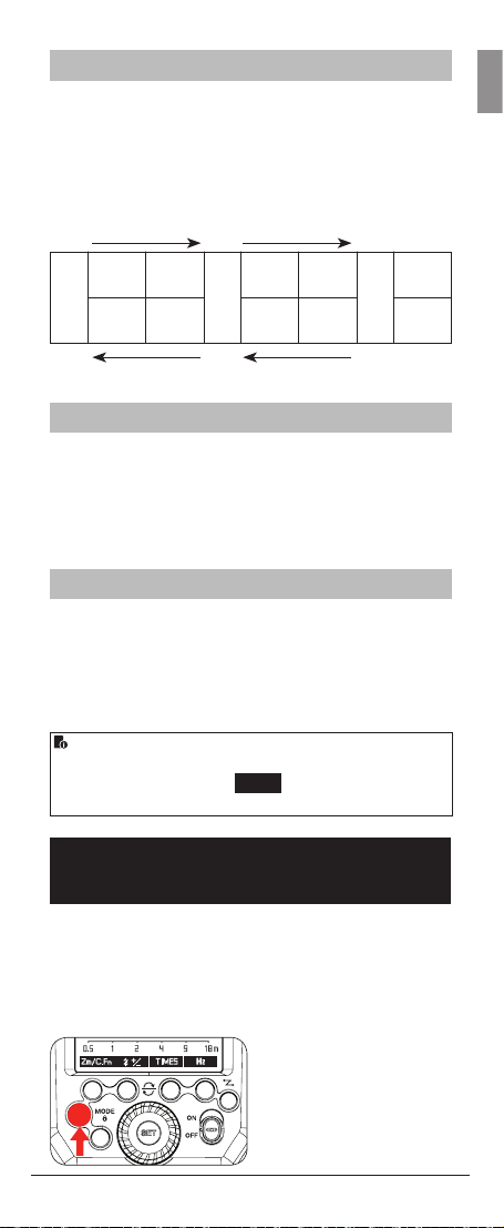
Flash Mode: MULTI (Stroboscopic
Flash)
With stroboscopic ash, a rapid series of ashes is red.
It can be used to capture multiple images of a moving
subject in a single photograph.
You can set the ring frequency (number of ashes per
sec.expressed as Hz), the number of ashes, and the
ash output power.
1. Press <MODE> button
so that < MULTI > is
displayed
2. Turn the Select Dial
to choose a desired ash
output power
Modus 600RT 21
Page 22
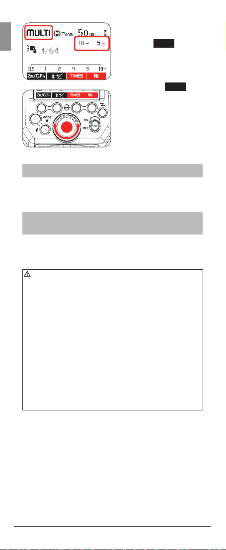
SET
3. Set the ash frequency
GB
and number of ashes
• Press <
Times
button
• Turn the Select Dial
to set the number of
ashes
• Press the <
• Turn the Select Dial to
choose a desired ash
ring frequency
• After you nish
the setting, press
<SET> button and
all the settings will be
displayed.
Calculating the Shutter Speed
During stroboscopic ash, the shutter remains open until
the ring stops. Use the formula below to calculate the
shutter speed and set it on the camera.
Number of Flashes / Flash Frequency
= Shutter Speed
For example, if the number of ashes is 10 and the ring
frequency is 5 Hz, the shutter speed should be at least 2
seconds.
• To avoid overheating and deteriorating the ash head,
do not use stroboscopic ash more than 10 times in
succession
• After 10 times, allow the speedlight to rest for at least 15
minutes. If you try to use the stroboscopic ash more than
10 times in succession, the ring might stop automatically
to protect the ash head. If this happens, allow at least 15
minutes’ rest for the speedlight
• Stroboscopic ash is most effective with a highly reective
subject against a dark background
• Using a tripod and a remote control is recommended.
• A ash output of 1/1 and 1/2 cannot be set for stroboscopic
ash
• Stroboscopic ash can be used with“buLb”
• If the number of ashes is displayed as “--”, the ring
will continue until the shutter closes or the battery is
exhausted. The number of ashes will be limited as shown
by the following table.
>
H
Z
>
22 Modus 600RT
Page 23

Maximum Stroboscopic Flashes:
If the number of ashes is displayed as “--”, the maximum number of
ashes will be as shown in the following table regardless of the ash
frequency.
GB
Modus 600RT 23
Page 24
GB
Wireless Flash
Photography:
3
Master/Slave wireless ash lighting
• The “Modus 600RT” attached to the Camera Hot shoe is
called the “Master” unit. A second “Modus 600RT” which is
wirelessly controlled is called the “Slave” unit
• You can also wirelessly control the Modus 600RT as a
“Slave” unit using a “Viper TTL” transmitter as a “Master”
unit attached to the camera hotshoe
Using (Master/Slave) with wireless 2.4GHz control
function allows you to easily perform shooting with
advanced wireless multiple ash lighting in the same way
as TTL autoash photography. The system is designed so
that the settings of the “Master” attached to the camera
are automatically applied to the wireless slave speedlights.
Therefore you do not need to operate or adjust the slaves
during shooting
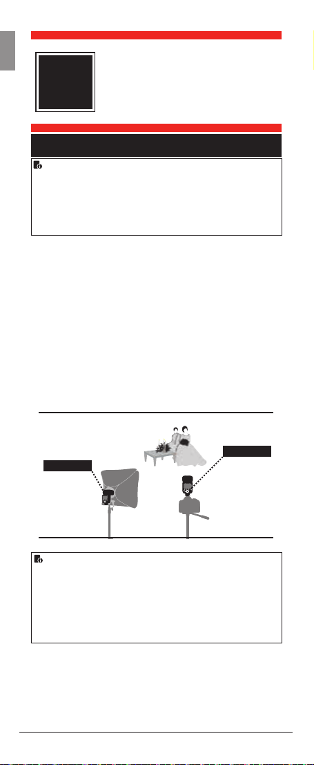
Positioning and Operation Range (Example of
wireless ash shooting)
• Master/Slave wireless ash lighting
SLAVE
(2.4GHz) Control
MASTER
2.4GHz
wireless
control
with up to
100m range
• The “Master” attached to the camera can be a “Modus
600RT” or “Viper TTL transmitter”
• Use the supplied mini stand to hold the Slave unit in
upright position
• Before shooting perform a test falsh and test shooting
• The transmission distance may vary depending on the
position of the slave speedlight, enviorment and weather
conditions
24 Modus 600RT
Page 25
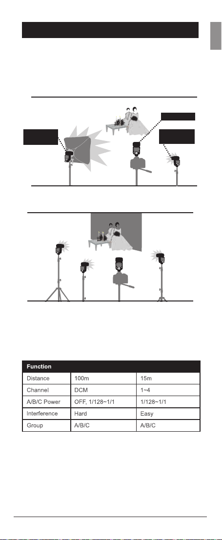
Wireless multiple ash shooting
You can divide the slave units into one, two or three
groups and perform TTL autoash. In addition, you can set
and shoot with a different ash mode for each ring group,
for up to 3 groups, plus master.
• Auto Shooting with Two Slave Groups
MASTER
GB
SLAVE
GROUP A
SLAVE
GROUP B
● Auto Shooting with Three Slave Groups
A
B
M
C
Wireless shooting using radio transmission has
advantages over wireless shooting using optical control,
such as being less affected by obstacles, and not having
to point the slave unit’s wireless sensor
toward the master unit. The main functional differences
are as follows:
Radio Control Optical Control
Modus 600RT 25
Page 26
Wireless Settings
GB
You can switch between normal ash and wireless ash.
For normal ash shooting, be sure to set the wireless
setting to OFF
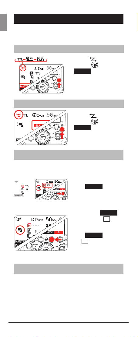
Master Unit Setting
Press < > button
so that <
MASTER
on the LCD panel.
Slave Unit Setting
> and <
> are displayed
Press <
so that <
SLAVE
> button
> and <
> are displayed
on the LCD panel
Master Unit Flash ON/OFF
You can switch ON or OFF the “Master” unit ash that is
controlling the wireless “Slave” units. When Master ash is
ON, it will ash as group M
1. Press Function Button
Gr
4 <
> and one
Group M/A/B or C will
be highlighted
2. Press Function
Gr
Button 4 <
again until <
>
M
> is
highlighted
3. Press Function Button
MODE
3 <
<
M
> until
> is <--->. The
master speedlight is
now OFF
Setting the group mode - TTL / M / OFF
From the “Master” Modus Speedlight each Group M
(master speedlight) / A / B / C “mode” setting can be
adjusted individually.
26 Modus 600RT
Page 27

1. Press Function Button
Gr
Gr
MODE
>
> until < A
> and
4 <
• Keep pressing Button 4
<
> is highlighted
2. Press Function Button
3 <
select the desired Mode
TTL <TTL> / Manual
<M> / Off <--->
Setting the DCM
(Digital Channel Matching)
Initialy the Modus 600RT wireless 2.4GHz is set to a
general “open channel” and can be used as it is. To
avoid interference with other wireless ash systems we
recommend to DCM (digital channel match) your Modus
600RT speedlight’s and Viper TTL.
Master – Viper TTL or Modus 600RT
1. If you have a Viper TTL,
start the DCM matching
with the Viper TTL
• Turn < ON > the Viper
TTL transmitter whilst
holidng down the < test
> button and release
<test> button after 2
seconds
• The Viper LCD will
show < Co di ng>
2. If you are not using a
Viper TTL and only wish
to DCM several Modus
600RT, then use any
Modus 600RT as the
Master unit
• Press <Function
Button 1> whilst turning
< ON > the power to the
Modus 600RT
• A green LCD on the
M o d u s 6 0 0 R T w i l l s h o w
MASTER
<
>
GB
Slave - Modus 600RT
3. Press <Function
Button 2> whilst turing <
ON > power to the slave
Modus 600RT
Modus 600RT 27
Page 28

OK
4. A red LCD will show
GB
“Slave OK”. This slave
Modus 600 RT is now
DCM matched
5. DCM match the same
way, any additional slave
Modus 600RT while the
Master is still on
Once all slave units are DCM matched, reboot all master and
slaves by turning OFF/ON
• Once all devices are DCM matched they will memorieze
the unique ID even it power is removed. Therfore you only
need to DCM your set once
• If you add more speedlights or Viper TTL units to your
range then you need to carry out the DCM matching for all
your units again
Modus 600 RT - Reset
• To reset the Modus
600RT to factory default
settings press function
buttons 3 & 4 at the
same time and hold
until the LCD shows <
RESET
buttons
• When the Modus
600RT is reset the DCM
is also reset back to
open channel and the
previous DCM is lost
> release the
TTL Fully Automatic Wireless
Flash Shooting
Basic Automatic Wireless Flash shooting
with a Single Slave Unit
1. Master Unit Setting
• Attach a Modus 600RT
to the camera and set
it as the master unit
(Page 26)
• The Viper TTL
Transmitter can also be
used as a master unit
to control the wireless
slave Modus 600RT
(Page 38)
28 Modus 600RT
Page 29
2. Slave Unit setting
• Set the slave Modus
600RT to <
setting (Page 26)
3. Position of camera
and speedlight
• Position the camera
with the master unit
attached and the Modus
slave within radio range
4. Set the Group
mode to <TTL>
• Check that group <
> is set to <TTL>. If
not press <
> button until <TTL> is
displayed
• Check that the slave
unit is set automatically
to <TTL> by the master
unit
SLAVE
A
MODE
>
ash
A
5 Check Master/Slave
units are ready
• Check master
speedlight, ready
indicator is lighting and
that the slave ash
ready indicators are
blinking
6 Check the Master
slave speedlight
operation
• Press the master unit’s
> test button
<
• The slave speedlight
will ash. If it does not
re, check the position
or distance of slave
from master
• You are now ready to
take a photo with the
wireless ash lighting
GB
Modus 600RT 29
Page 30

Using Automatic Wireless Flash
GB
with Multiple Slave Units
When stronger ash output or more convenient lighting
operation is needed, increase the number of slave
speedlight’s. To add slave units, use the same steps as
setting “automatic wireless ash with a single slave
unit” (Page 28). Any slave speeedlight can be set as
group (A/B/C).
When the number of slave units is increased or the
master ash ring is set to ON, automatic control is
performed to re all ashes at the correct ash output to
ensure that the total ash output results in the standard
exposure.
• If the slave units auto power off takes effect, press the
master unit’s test ash button to turn on the slave unit.
Note that the test ash cannot be performed while the
camera’s metering timer, etc. is operating
• The slave units auto power off setting can be changed
(C.Fn-Sv / APOT page 42)
• In the C.Fn settings you can enable a beeper to sound
when a Modus 600RT is recharged and ready to re again
Advanced setting with fully automatic
wireless ash
With the wireless system the following functions set on
the master unit will automatically be adjusted on the slave
unit. For this reason you do not need to operate the slave
unit (s) and can operate it from the master in the same
way as normal ash photography.
• Flash Exposure Compensation <
• Manual Flash (Page 20)
• MULTI: Stroboscopic Flash
30 Modus 600RT
(Page 21)
> (Page 18)
Page 31

Multiple Master Unit
You can use two or more cameras with master ash
units on each to change camera shooting while keeping
the same lighting setup (slave units) in wirelesss ash
photography.
M: Wireless Flash Shooting with
Manual Flash
This describes wireless using manual ash. You can shoot
with a different ash output setting for each slave unit
(ring group). Set all parameters on the master unit.
1. Setting the manual
ash mode to <M>
• Press Function Button
Gr
4 <
the group
• Then press Function
Button 3 <
set the <M> mode
2. Setting manual ash
output power
• Press Function Button
2 <
Select Dial to adjust the
ash output of the group
• Press <SET> button to
conrm
3. Setting individual group
ash output power
4. Each group M (Master
speedlight) / A / B / C
can be set individually
to different power level
• Set any group to <--->
to turn the power of this
group
> to choose
MODE
> to
>. Turn the
GB
MULTI: Wireless shooting with
Multi repeating ash stroboscop-
1. Setting <MULTI>
stroboscopic ash
• On the Master
Speedlight press
<MODE> button until
<MULTI> is displayed
• Turn the Select Dial to
adjust the ash output
power. Press <SET>
button to conrm
Modus 600RT 31
Page 32

2. Turning ON/OFF group
GB
M (master speedlight)
/ A / B / C
• Press Function Button
Gr
3 <
>. Then turn
the Select Dial to set
the group ON/OFF
• Press Function Button
Gr
3 <
> again to
select the next group.
Press <SEL> button to
conrm
3. Setting the
stroboscopic ash
parameters
• Press Function Button
MENU1
4 <
will display <
>. This
MENU2
> which enables
selecting of power
<
>, number
ashes <
Times
frequency <
• Press <
Times
> or <
to adjust the relevant
setting
M/A/B/C: Wireless ash shooting
with different ash modes for
each goup
You can shoot with different ash modes set for each ring
group (M/A/B/C). The ash modes that can be set are
TTL auto ash / manual / OFF. When the ash mode is in
TTL exposure is controlled to result in standard exposure
for the main subject as a single group. This function is
for advanced user who are very knowledgeable and
experienced in lighting.
Hz
> or <
Hz
> and
>
>
SLAVE
A
SLAVE
B
SLAVE
C
MASTER <M>
32 Modus 600RT
Page 33

1. Set master Unit
• Press the <
MODE
>
button and set the ash
mode to <
MASTER
> .
See Page 26
2. Set the ring group of
the slave units
• Operate and set the
slave units one by one
• Press Function Button
Gr
<
> to assign
the speedlight to group
<A>, <B> or <C>. See
3. Set the ash modes
• Set the ash mode of
each ring group by
the operation of the
master speedlight. See
Page 27
4. Set the ash output
and ash exposure
compensation amount
• While a ring group
is selected, press
Function Button 3 <
>
• Turn the Select Dial to
set the ash function
corresponding to
ash mode, and press
<SET> Button to
conrm
• When using the <M>
mode, set the ash
output power
• When using the <TTL>
mode, set the ash
exposure compensation
amount as required
• Repeat step 4 to set
the ash function of all
groups
• Press Function Button
4 to return to the
shooting-ready state
GB
Modus 600RT 33
Page 34

GB
Wireless Flash
Photography:
4
Optical O1 Secondary Unit Setting
In M manual ash mode, press <O1/O2> button so that
this ash can function as an optical O1 secondary off
camera ash using its optical sensor. With this function,
the ash will re synchronously when a second main ash
res on the camera. This is the same effect as usng a
radio trigger to re the ash off camera. This helps create
multiple lighting effects.
Optical O2 Secondary Unit Setting
In M manual ash mode, press <O1/O2> button so that
this ash can function as an optical O2 secondary off
camera ash using its optical sensor. With this function,
the ash will re synchronously when a second main ash
res on the camera as in O1 but it will ignore the metering
pre-ash and re only in response to the exposure ash
from the main unit.
• O1 and O2 optic triggering is only available in M manual
ash mode when the Modus 600 RT is off camera
• Press function button 4 <
when in 01/02 mode
Optical Transmission
SYNC
> to activate the “HSS”
34 Modus 600RT
Page 35

GB
Modus 600RT 35
Page 36

GB
Wireless Flash
Photography:
5
Viper TTL Transmitter
Wireless Settings
DCM (Digital Channel Matching)
1. DCM (Digital Channel Matching). Carry out the DCM
matching, see page 27
2. Set the Modus 600RT to 2.4GHz as Slave Unit - Group
A, see page 27
3. Press Viper <test>
Speedlight is triggered wirelessly
Viper TTL group Mode Setting
Press buttons A or B or C to change the MODE setting
of each group to <TTL>, <M> manual & <blank> OFF.
Take a test photograph now and the Viper transmitter
will send a wireless signal to each Modus 600RT. The
Speedlight will then be set automatically to the same Viper
TTL selected group mode setting.
• The Viper LCD 05 will show the setting of each group
• A group is turned OFF if the LCD is not showing the group
• A group is in Manual mode when <M> is displayed next
to the group
• A group is in TTL mode when <TTL> is displayed next to
the group
• Each group
possible to use simultaneously different setting for each
group (e.g. Group
and Group
08
A, B
or
A
may be in <M>, Group B in <TTL>
C
turned OFF)
(2.4GHz) using
button to conrm that Modus
C
is set independently and it is
Group Power Control setting for
Manual and TTL FEC
From the Viper TTL transmitter you can adjust the power
level and the FEC of each group.
4. Press <SEL>
<B> and <C> will ash.
5. Press one button
you want to adjust the power. Now only the selected
group icon <A or B or C> will ash
6. Use the adjust dial to set the power output in <
mode and FEC in TTL mode
7. Press the <SEL> button to lock your selection
36 Modus 600RT
02
select button and all three icons <A>,
A
or B or C to select which group
M
>
Page 37

Multi Mode
• Press and hold the < Group A > button to select
the Multi mode <
Group Buttons and adjust dial to set the number of
ashes, ash frenquency and power output. Press the
<SEL> button again to lock selection
• For more detail on operation of the viper TTL visit www.
hahnel.ie
MT
> icon. Use the <SEL> button,
GB
Modus 600RT 37
Page 38

GB
Other
6
Sync Triggering
• The Sync Cord Jack is a Φ2.5mm plug. Insert a trigger
plug here and the ash will be red synchronously with
the camera shutter.
• To avoid overheating and deteriorating the ash head, do
not re the modeling ash for more than 10 consecutive
times. If you re the modeling ash 10 consecutive times,
allow at least 10 minutes’ break for the camera ash.
Auto Focus Assist Beam
In poorly-lit or low-contrast shooting environments, the
built-in auto focus assist beam will automatically switch on
to make it easier to autofocus. The beam will light up only
when autofocus is difcult and will switch off as soon as
the autofocus is set.
If you want to turn off the auto focus assist beam, set “AF”
to “OFF” on the C.Fn settings.
• AFF Illuminator must be set to on in the camera menu
• If you nd the auto focus assist beam does not light up,
this is because the camera has got a correct autofocus.
Applications
Bounce Flash
By pointing the ash head toward a wall or ceiling, the
ash will bounce off the surface before illuminating the
subject. This can soften shadows behind the subject for a
more natural-looking shot. This is called bounce ash.
To set the bounce direction, hold the ash head and
turn it to the required angle.
-7-90
360
38 Modus 600RT
• If the wall or ceiling
is too far away, the
bounced ash might be
too weak and result in
underexposure.
• The wall or ceiling should
be a plain, white color for
high reectance. If the
bounce surface is not
white, a color cast may
appear in the picture.
Page 39

Catchlight Panel
With the catchlight panel, you can create a catchlight in
the subject’s eyes to add life to the facial expression.
1. Point the ash head
upward by 90°
2. Pull out the wide panel.
The catchlight panel
will come out at the
same time
3. Push the wide panel
back in
• Push in only the wide
panel
• Follow the same
procedures as for
bounce ash
ZOOM: Setting the Flash Coverage
and Using the Wide Panel
The ash coverage can be set automatically or manually.
It can be set to match the lens focal length from 20 mm
to 200mm. Also, with the built-in wide panel, the ash
coverage can be expanded for 14mm wide-angle lenses.
In Manual Zoom mode,
press the <ZM/C.FN>
button.
• Turn the Select Dial
to change the ash
coverage
A
• If <
> is displayed,
the ash coverage will
be set automatically
• If you set the ash coverage manually, make sure it covers
the lens focal length so that the picture will not have a dark
periphery.
GB
Using the Wide Panel
Pull out the wide panel
and place it over the ash
head as shown. The ash
coverage will then be
extended to 14 mm.
• The catchlight panel
will come out at the
same time. Push the
catchlight panel back in.
• The <ZOOM/C.FN>
button will not work.
Modus 600RT 39
Page 40

C.Fn: Setting Custom Functions
GB
The following table lists the available and unavailable
custom functions of this ash.
Zoom
APS 14mm 133mm
135 20mm 200mm
1. Software Version
Press <Zm/C.Fn> Backlight/Custom Setting Button for
2 seconds or longer until C.Fn menu is displayed. The
“Ver x.x” in the topright corner refers to the software
version.
2. Select the Custom Function No
• Turn the Select Dial to select the Custom Function
number
3. Change the Setting
• Press <SET> button and the Setting No. blinks.
• Turn the Select Dial to set the desired option. Pressing
<SET> button will conrm the settings.
• After you set the Custom Function and press function
button 4, the camera will be ready to shoot.
4. C.Fn Default
In the C.Fn menu, a long press of the “Clear” button for
2 seconds until “OK” is displayed on the panel, which
means the values in C.Fn are reset to their default
options
40 Modus 600RT
Page 41

Protection Functions
1. Over-Temperature Protection
• To avoid overheating and deteriorating the ash
head, do not re more than 30 continuous ashes in
fast succession at 1/1 full power. After 30 continuous
ashes, allow a rest time of at least 10 minutes
• If you re more than 30 continuous ashes and then
re more ashes in short intervals, the inner overtemperature protection function may be activated and
make the recycling time over 10 seconds. If this occurs,
allow a rest time of about 10 minutes, and the ash unit
will then return to normal
• When the over-temperature protection is active,
> is shown on the LCD display
<
Number of
ashes that
will activate
overtemperature
protection:
Power Output level
1/1
1/2 +0.7
1/2 +0.3
1/2
1/4(+0.3,+07)
1/8(+0.3,+07)
1/16(+0.3,+07)
1/32(+0.3,+07)
1/64(+0.3,+07)
1/128(+0.3,+07)
Number
of Flashes
30
40
50
60
100
200
300
500
1000
GB
Number of ashes that
will activate overtemperature
protection in high-speed
sync triggering mode:
Modus 600RT 41
Power Output Times
1/1
1/2(+0.3,+07)
1/4(+0.3,+07)
1/8(+0.3,+07)
1/16(+0.3,+07)
1/32(+0.3,+07)
1/64(+0.3,+07)
1/128(+0.3,+07)
15
20
30
40
50
Page 42

2. Other Protections
The system provides real-time protection to secure the
GB
device and your safety. The following lists prompts for your
reference:
Prompts on
Meaning
LCD Panel
E1
A failure occurs on the recycling
system so that the ash cannot re
Please restart the ash unit. If the
problem still exists, please send this
product to a maintenance center
E2
E3
E9
The system gets excessive heat.
Please allow a rest time of 10 minutes
The voltage on two outlets of the ash
tube is too high. Please send this
product to a maintenance center
There are some errors occurred during
the upgrading process. Please use the
correct rmware upgrade method
42 Modus 600RT
Page 43

Technical Data
Modus 600RT
Fujilm Cameras
TTL autoash and manual ash
O1/O2
M/ A / B/ C
GB
200Hz)
Modus 600RT 43
Page 44

Troubleshooting
GB
If there is a problem, refer to this Troubleshooting Guide.
The Camera Flash does not re.
• The camera ash is not attached securely to the
camera.
• →Attach the camera’s mounting foot securely to the
camera.
• The electrical contacts of the Camera Flash and camera
are dirty.
• →Clean the contacts.
• < > or < > is not displayed in the view nder of
camera.
• →Wait until the ash is fully recycled and the ash
ready indicator lights up.
• →If the ash ready indicator lights up, but < > or
< > is not displayed in the view nder, check whether
this ash unit is securely attached to the camera
hotshoe.
• →If the ash ready indicator does not light up after a
long wait, check whether the battery power is enough. If
the battery power is low, <
the LCD panel. Please replace the battery immediately.
The power turns off by itself.
• After 90 seconds of idle operation, auto power off took
effect if the ash is set as master.
• →Press the shutter button halfway or press any ash
button to wake up.
• After 60 minutes (or 30 minutes) of idle operation, the
ash unit will enter sleep mode if it is set as slave.
• →Press any ash button to wake up.
•
Auto zoom does not work
• The camera ash is not attached securely to the
camera.
• →Attach the camera ash’s mounting foot to the
camera.
The ash exposure is underexposed or overexposed.
• There was a highly reective object (e.g. glass window)
in the picture.
• You used high-speed sync.
• →With high-speed sync, the effective ash range will
be shorter. Make sure the subject is within the effective
ash range displayed.
• You used Manual Flash mode.
• →Set the ash mode to TTL or modify the ash output.
Photos have dark corners or only parts of the target
subject are illuminated.
• The focal length of lens exceeds the ash coverage.
• → Check the ash coverage you set. This ash unit
> will appear and blink on
44 Modus 600RT
Page 45

has the ash coverage between 20 and 200mm, which
ts medium-format cameras. Pull the wide panel out to
extend the ash coverage.
Firmware Upgrade
This ash supports rmware upgrade through the USB
port. Update information will be released on our ofcial
website.
• USB connection cable is not included in this product. The
USB port is a standard Micro USB socket. Common USB
connection cable is suitable.
Compatible Camera Models
• For up to date compatibility of all camera models check
www.hahnel.ie
Maintenance
• Shut down the device immediately should abnormal
operation be detected
• Avoid sudden impacts and the product should be
cleaned regularly
• It is normal for the ash tube to be warm when in use.
Avoid continuous ashes if unnecessary
• Maintenance of the ash must be performed by our
authorized maintenance department which can provide
original accessories
• This product, except consumables e.g. ash tube, is
supported with a one-year warranty
• Unauthorized service will void the warranty
• If the product has malfuctioned or has been damaged
by water do not use until it is repaired by a professional
• Changes made to the specications or designs may not
be reected in this manual
GB
This Product complies with the EU Radio
Equipment Directive 2014/53/EU. For compliance
data visit www.hahnel.ie
Modus 600RT 45
Page 46

GB
46 Modus 600RT
Page 47

MKII
FR
Speedlight sans l
de Fujilm
Français
Modus 600RT 1
Page 48

FR
2 Modus 600RT
Page 49

Avant-propos
Merci d’avoir acheté le Modus 600RT.
Le Modus 600RT est un Speedlight pour les
séries d’appareils photos Fujilm DSLR et est
compatible avec le système de ash automatique
TTL intelligent.
• Avant de commencer à lmer, lisez ce manuel
• En lisant ce manuel, référez-vous également au
manuel d’utilisation de l’appareil photo
Conventions &
hypothèses
• Le manuel est basé sur l’hypothèse selon
laquelle tous les appareils, y compris l’appareil
photo, sont allumés
• Le numéro de page de référence est indiqué
par le symbole (page **)
Le symbole de mise en garde indique un
•
avertissement à éviter les problèmes de prise
de vue
Le symbole Remarque fournit des
•
informations supplémentaires
FR
Modus 600RT 3
Page 50

Contents
1 Introduction
• Mesure de précaution - Avertissements et
FR
mises en garde
• Nomenclature
• Corps
• Panneau de commande
• Panneau ACL en cinq modes
• Transmetteur Viper TTL
2 Démarrage
• Que contient le Modus 600RT? 14
• Que contient le kit sans l Modus 600RT?
• Batterie et chargeur
• Fixer à un appareil photo
• Gestion d’énergie
• Mode Flash - Flash automatique TTL intelligent
• FEC (Correction d’exposition au ash)
• HSS (Synchronisation haute vitesse)
• Synchronisation du second rideau
• Mode Flash - Flash manuel
• Plage de puissance de sortie du ash
• Réglage de l’unité secondaire optique O1
• Réglage de l’unité secondaire optique O2
• Mode Flash - Multiple : Flash stroboscopique
• Calcul de la vitesse d’obturation
• Nombre de ashs / fréquence du ash
= vitesse du ash
3 Photographie sans l : Commande (2.4GHz)
• Éclairage ash sans l Maître / Esclave 24
• Prise de vues multi-oblique sans l
• Réglages sans l
• Réglage de l’unité maître
• Réglage de l’unité esclave
• Flash de l’unité maître Activer/Désactiver
• DCM (correspondance de canaux
numériques) 26
• DCM (correspondance de canaux numériques)
• Maître - Viper TTL ou Modus 600RT
• Esclave - Modus 600RT
• Modus 600RT - réinitialisation
• TTL intelligent- Prise de vue avec ash sans
l entièrement automatique 28
• Utiliser le ash sans l automatique avec
plusieurs unités esclaves
• Réglage avancé avec ash sans l
entièrement automatique 30
• Unité multiple maître
• M : Prise de vue avec ash sans l avec
ash manuel 31
• MULTI : Prise de vue avec ash sans l avec
ash stroboscopique 31
• M/A/B/C: Prise de vue avec ash sans l avec
différents modes de ash pour chaque groupe
4 Modus 600RT
Page
11
12
14
14
17
17
18
19
20
20
21
21
21
21
22
22
25
26
26
26
27
27
27
28
30
31
32
6
8
9
Page 51

Page
4 Photographie sans l : Transmission optique
• Réglage de l’unité secondaire optique O1 34
• Réglage de l’unité secondaire optique O2 34
5 Photographie sans l : (2.4GHz) utiliser le
transmetteur Viper TTL
• Réglage sans l
• DCM (Compatibilité des canaux
numériques) 36
• Réglage du mode groupe Viper TTL
• Réglage de la commande de puissance
de groupe pour le manuel et le TTL FEC 36
• Mode multi
6 Autres applications
• Déclenchement de synchronisation
• Faisceau d’assistance autofocus
• Flash indirect
• Panneau de capture de lumière
• Zoom - Réglage de la portée du ash et
utilisation du panneau large
• C.Fn – Réglage de fonctions personnalisées
• Fonctions de protection
• Données techniques
• Résolution des problèmes
• Mise à jour du microprogramme
• Entretien
FR
36
36
37
38
38
38
39
39
40
41
43
44
45
45
Modus 600RT 5
Page 52

FR
Introduction
1
Avertissements
Le non-respect des instructions ci-dessous
pourrait entraîner des pertes en vies humaines ou
des blessures graves. Pour éviter les incendies,
la chaleur excessive, les fuites de produits
chimiques, les explosions et les chocs électriques,
respectez les garanties ci-dessous :
• N’insérez pas d’objets métalliques étrangers
dans les contacts électriques du produit, les
accessoires, les câbles de connexion, etc.
• N’utilisez pas de batteries, de sources
d’énergie ou d’accessoires non spéciés
dans le manuel d‘utilisation. N’utilisez pas de
batteries déformées ou modiées, ou le produit
s’il est endommagé
• Ne pas court-circuiter, démonter ou modier
le produit ou les batteries. N’appliquez pas de
chaleur ou de la soudure sur les batteries.
• N’entreposez pas les batteries avec des objets
métalliques. N’exposez pas les batteries au feu
ou à l’eau. N’exposez pas les batteries à un
choc violent ou à un choc mécanique continu
• Ne placez pas les batteries dans un microonde,
sur une cuisinière ou dans un récipient à haute
pression
• N’utilisez pas le produit dans des endroits où il
y a du gaz inammable
• Ne dirigez pas le ash vers toute personne
conduisant une voiture ou vers un autre
véhicule
• Ne pas démonter ni modier l’appareil. Les
pièces internes à haute tension pourraient
causer des chocs électriques Si vous laissez
tomber l’appareil et que le boîtier se brise et
les pièces internes sont exposées, ne pas
toucher pas les pièces exposées. Il existe une
possibilité de choc électrique
• N’entreposez pas le produit dans des
endroits poussiéreux ou humides ou dans un
endroit avec beaucoup de fumée huileuse.
:
6 Modus 600RT
Page 53

N’entreposez pas la batterie sur le chargeur
• Gardez les batteries et autres accessoires hors
de portée des enfants et des bébés
• Ne laissez pas tomber le produit ou la batterie
dans du feu ou dans de l’eau
• N’exposez pas le produit ou la batterie à une
température excessive (inférieure à 0° C ou
supérieure à 40 °C) ou à une forte lumière du
jour
• La température de la batterie en charge ou en
cours d’utilisation ne doit jamais être supérieure
à 60ºC / 140ºF. En cas de température
plus élevée, arrêtez d’utiliser et arrêtez
immédiatement la charge
• N’utilisez pas du diluant à peinture, du benzène
ou d’autres solvants organiques pour nettoyer
le produit
FR
Mise en garde
• Le non-respect des instructions ci-dessous
pourrait entraîner des blessures corporelles
graves ou des dommages matériels
• Lorsque le produit n’est pas utilisé pendant une
longue période, retirez les batteries avant de le
ranger
• Avant de vous débarrasser d’une batterie,
isolez les contacts électriques avec du
ruban adhésif. Le contact avec d’autres
objets métalliques ou des batteries pourrait
provoquer un incendie ou une explosion. Se
débarrasser de la batterie conformément aux
règlementations appropriées
• Ne rangez pas ou ne laissez pas le produit
ou la batterie dans un coffre ou sur le tableau
de bord d’un véhicule ou en plein soleil ou à
une température intérieure élevée, car une
surchauffe pourrait provoquer des brûlures en
cas de fuite, d’incendie ou d’explosion
• Ne déclenchez pas le ash avec la tête du ash
(unité d’émission de lumière) en contact avec
un corps humain ou tout autre objet pouvant
causer des risques de brûlures et d’incendie
• Ne dirigez pas le ash près des yeux. Placez
l’unité du ash au moins à 1 m du visage. Il
pourrait blesser ou endommager les yeux.
L’utilisation du ash indirect pour réduire
l’intensité de la lumière est également
recommandée
:
Modus 600RT 7
Page 54

Nomenclature
01
02
FR
03
04
05
06
10
07
08
09
11
12
Contenu de la nomenclature
01. Panneau de capture de
lumière
02. Panneau large intégré
03. Tête du ash
04. Capteur de commande
optique
05. Faisceau d’assistance de
focalisation
06. Indicateurs de ash
esclave prêts
8 Modus 600RT
07. Synchronisation du
cordon Jack
08. Port USB
09. Sabot ash
10. Panneau ACL à matrice à
points
11. Compartiment batterie
12. Verrouillage rapide
Page 55

Nomenclature - Panneau de commande
13 18
14
15
16
17
13. Bouton de fonction 2
14. Bouton de fonction 1
15. <
> Bouton de sélection
du mode / bouton de
verrouillage
16. <
> Bouton de test /
indicateur de ash prêt
17. <SET> Bouton de
réglage
18. Bouton de fonction 3
19. Bouton de fonction 4
20. <
> Mode sans l /
maître / esclave
21. Interrupteur On / Off
22. Cadrant de sélection
Nomenclature – Panneau
01 02 03 04 05 06
FR
19
20
21
22
07
08
(1) Flash automatique TTL intelligent
01. Flash automatique TTL
intelligent
: Automatique
02.
: Manuel
03. Zoom: Afchage du
zoom
04. Distance de focalisation
: Synchronisation
05.
haute vitesse
06. Indicateur de niveau de
batterie
• L’écran afche uniquement les réglages actuellement appliqués.
• Les fonctions afchées au-dessus des touches de fonction 1 à
4, telles que
des réglages.
• Lorsqu’un bouton ou un cadrant est actionnée, le panneau ACL
s’allume. illuminated.
Modus 600RT 9
et modiées en fonction du statut
: Correction
07.
d’exposition au ash
08. Niveau de correction
d’exposition au ash
09. Orice
10. Échelle d’indicateur de la
distance
11. Portée effective du ash
Signal sonore activé/
12.
désactivé (C. Fn 7)
12
09
10
11
Page 56

(2) Flash Manuel
O1: Optique standard. 02: Optique avec pré-ash
FR
M : Flash manuel Puissance de sortie du ash manuel
(3) Multi: Flash stroboscopique multi
Puissance du ash Nombre de clignotements
MULTI : Flash stroboscopique multi
fréquence de
clignotement
(4) Prise de vue avec commande radio
(a) Unité maître - Mode ash
15
16
19
17
20
18
:Unité maître Flash désactivé
15. : Prise de vue sans
l avec commande radio
16. Mode ash: <Vide>,
<MULTI>
17. :Unité maître Flash
activé
10 Modus 600RT
:Unité maître du ash
indirect Activé
18. : Maître
19. Groupe maître: Mode
20. Groupe A.B / C: Mode
Page 57

(b) Unité esclave
Mode esclave Groupe A/B/C...
Trois modes afchés à l’écran
(1) Fixé à l’appareil photo
(2) Contrôle radio 2.4GHz : En tant qu’unité maître
FR
(3) Contrôle radio 2.4GHz : En tant qu’unité esclave
Groupe A
Modus 600RT 11
Page 58

Nomenclature - Transmetteur Viper
TTL
08
A B C
FR
09
07
06
01
02
05
(A) Groupe A
04
(B) Groupe B
(C) Groupe C
(1) Activé /Désactivé -
interrupteur
(2) SEL - choisir le bouton
(3) Ajustez le cadrant - Pour
régler les réglages
03
(4) Verrouillage de roue
(5) Écran ACL
(6) Puissance / Statut du voyant
(7) Sabot ash
(8) Test - bouton
(9) Micro USB – Mise à jour du
microprogramme
12 Modus 600RT
Page 59

Écran transmetteur ACL
10
16
1211
Mode multiple
B CA
191817
FR
13
14
15
(10) Manuel / TTL / Mode
désactivé
(11) Niveau de correction de
l’exposition au ash
(12) Sortie du ash manuel
(13) Synchronisation haute-
vitesse
(14) 2ème synchronisation du
rideau
(15) Toujours Activé
(16) Indicateur de niveau de
batterie
(17) Nombre de clignotements
(18) Fréquence de clignotement
(19) Puissance de sortie du ash
• Le transmetteur Viper est inclus dans le kit sans l Modus
600RT
Modus 600RT 13
Page 60

FR
Démarrage
2
• ?
Que contient le Modus 600RT?
1. Modus 600RT Speedlight
2. Pack de batterie Li-ion
3. Chargeur de batterie
4. Câble Micro USB
5. Mini support
6. Boîtier de protection
7. Manuel d’utilisation
Que contient le kit sans l
Modus 600RT?
1. Modus 600RT Speedlight
2. Viper TTL Transmitter
3. Pack de batterie Li-ion
4. Chargeur de batterie
5. Câble Micro USB
6. Mini trépieds
7. Boîtier de protection
8. Manuel d’utilisation
9. Batteries AA x 2
Batterie et chargeur
• La batterie HLX-MD1 doit être chargée avant utilisation.
• Utilisez le chargeur MD1 MKII fourni pour charger la
batterie.
• Retirez la batterie du chargeur lorsque la charge est
terminée et débranchez le chargeur du secteur Une
batterie complètement chargée offrira environ 500
ashs à pleine puissance et encore plus lorsque le
niveau de puissance est réduit. La composition et
la construction du pack de batterie MD1 offrent un
temps de rafraîchissement très able et rapide pour le
speedlight
Comment ranger la batterie
Lorsque la batterie n’est pas utilisée, retirez-la du
chargeur ou du speedlight et rangez-la dans un endroit
frais et sec. Exposez la batterie à une température plus
élevée peut raccourcir la durée de vie de la batterie.
Rangez la batterie presque vide (une barre dans
l’indicateur de niveau de batterie) lorsqu’elle n’est pas
utilisée pendant une longue période de temps. Pour
une durée de vie optimale de la batterie, utilisez-la
régulièrement et, si elle n’est pas utilisée pendant plus
de 6 mois, chargez complètement la batterie et utilisez-la
avec le Modus 600RT jusqu’à ce que le niveau de la
batterie dépasse 1 barre avant de la ranger.
14 Modus 600RT
Page 61

Durée de vie de la batterie
La durée de vie d’une batterie rechargeable est limitée.
La capacité diminue progressivement avec l’utilisation et
l’âge du pack de batterie. Remplacez le pack de batterie
lorsque le temps de cycle du ash devient plus long ou
le nombre de ashs diminue sensiblement. La durée
de vie de la batterie peut varier considérablement en
fonction de la façon dont elle est rangée, des conditions
de fonctionnement et de l’exposition à des conditions
environnementales inadéquates.
Mise en garde
• Ne pas court-circuiter la batterie
• Ne pas laisser pas la batterie dans de l’eau ou du feu
• Ne pas laisser tomber ou démonter ou soumettre les
batteries à un impact fort ou à un choc mécanique
continu
• Arrêtez d’utiliser la batterie si elle présente des signes
d’endommagement ou de gonement dans le boîtier
et jeter la batterie conformément à la règlementation
locale appropriée
Comment charger la batterie
La batterie HLX-MD1 doit être chargée avant utilisation.
Utilisez le chargeur MD1 MKII fourni pour charger la
batterie.
Connectez le chargeur MD1 MKII à un adaptateur USB
(min 5V 2 Amp) avec le câble Micro USB fourni.
Pour commencer la charge, insérer la batterie HLX-MD1
dans le chargeur MD1 MKII, la première barre LED verte
s’allume pour indiquer que la batterie est en charge.
Lorsque les 4 barres LED vertes sont allumées, la charge
est terminée, retirer la batterie du chargeur et débranchez
le chargeur du réseau électrique.
FR
Modus 600RT 15
Page 62

Montage et retrait de la batterie
1. Pour monter la batterie,
poussez le couvercle
FR
du compartiment de la
batterie vers le bas et
ouvrez-le.
2. Selon le signe
triangulaire sur le pack
de batterie, insérez-la
dans le compartiment
jusqu’à ce qu’une pince
blanche verrouille la
batterie en émettant
un clic.
3. Pour retirer la batterie,
appuyez sur la pince
blanche et le pack
de batterie s’afche.
Ensuite, fermez le
compartiment.
Indication du niveau de la batterie
Assurez-vous que la batterie est bien xée au ash.
Vériez l’indication du niveau de la batterie sur l’écran
ACL pour voir le niveau de batterie restant.
Avertissement de batterie faible
Indication de
niveau de batterie
3 barres
2 barres
1 barre
Aucune barre
Clignotant
16 Modus 600RT
Signie
Pleine
À moitié
Faible
Batterie faible, rechargez-la
Le niveau de la batterie sera utilisé
immédiatement.
Remarque : Veuillez recharger la
batterie le plus tôt possible (dans
les 10 jours). Ensuite, la batterie
peut être utilisée ou rangée telle
que indiquée dans la section «
Comment ranger la batterie »
Page 63

Fixer à un appareil photo
1. Connectez le ash
à l’appareil photo.
Glissez le pied pour
montage ashs dans le
sabot ash de l’appareil
photo jusqu’au bout.
2. Sécuriser le ash -
Appuyez sur le bouton
de déverrouillage pour
faire tourner l’anneau
de verrouillage sur le
pied du ash jusqu’à ce
qu’il se verrouille vers la
droite.
3. Détacher le ash:
a) Appuyez sur le bouton
a
b
d e d éverrouillage.
b) Tournez l’anneau
de blocage vers la
c
gauche jusqu’à ce
q u ’ i l s o i t d e s se rr é.
c) Faites glisser le ash
hors de la griffe de
l’appareil photo.
Gestion de l’alimentation
Utilisez le bouton ON / OFF pour allumer ou éteindre le
ash. Éteignez le ash s’il ne sera pas utilisé pendant
une longue période. Régler comme ash maître, il s’éteint
automatiquement après une certaine période (environ 90
secondes) d’utilisation inactive. Appuyez à mi-course sur
l’obturateur de l’appareil photo ou appuyez sur n’importe
quel bouton ash activera le ash. Régler comme ash
esclave, il entrera en mode veille après une certaine
période (réglable, 60 minutes par défaut) d’utilisation
inactive. Appuyer sur n’importe quel bouton ash, activera
le ash.
FR
La désactivation de la fonction d’arrêt automatique est
recommandée lorsque le ash est utilisé hors champs.
(C.Fn-APO)
La désactivation de la fonction d’arrêt automatique est
recommandée lorsque le ash est utilisé hors champs.
(C.Fn-Sv APOT, Page 42)
Modus 600RT 17
Page 64

Mode Flash - Flash automatique TTL
intelligent
Ce ash dispose de trois modes de ash: TTL intelligent,
Manuel (M), et MULTI (Stroboscopique). En mode TTL
FR
intelligent, l’appareil photo et le ash fonctionnent
ensemble pour calculer l’exposition adéquate pour le sujet
et l’arrière-plan. Dans ce mode, plusieurs fonctions TTL
sont disponibles: FEC, HSS, deuxième synchronisation
de rideau, ash de modélisation. Ceux-ci peuvent être
contrôlés avec le Modus 600RT ou avec l’écran de menu
de l’appareil photo.
* Appuyez sur < MODE > Le bouton de sélection du mode et trois
modes ash s’afchent sur l’écran ACL un par un à chaque fois que
l’on appuie.
Mode TTL intelligent
Appuyez sur la touche < MODE > Sélection du mode
Bouton pour accéder au mode TTL intelligent.
L’écran ACL afchera TTL intelligent.
• Appuyez à mi-course sur le bouton déclencheur de
l’appareil photo la mise au point. L’ouverture et la plage
de ash effective s’afchent sur l’écran ACL.
Lorsque le bouton de l’obturateur est complètement
enfoncé, le ash déclenchera un pré-ash que l’appareil
photo utilisera pour calculer la puissance adéquate de
sortie du ash avant que la photo ne soit prise.
FEC: Correction d’exposition au ash
Avec la fonction FEC, vous pouvez régler le niveau
calculé de -3 à +3 en 1 / 3 arrêts. Il est important dans
des situations où un réglage minimal du système TTL est
nécessaire en fonction de l’environnement d’éclairage.
Réglage:
1. Appuyez sur le bouton
de fonction 2 <
>. L’icône < > et le
niveau de correction
d’exposition au ash
seront sélectionnées sur
l’écran ACL.
18 Modus 600RT
Page 65

SET
2. Réglez le niveau de
correction d’exposition
au ash.
• Tournez le cadrant de
sélection pour régler la
valeur.
• “0.3” signie 1/3 de pas,
“0.7”signie 2/3 de pas.
• Pour annuler la
correction d’exposition
au ash, réglez la valeur
sur “+0”.
3. Appuyez de nouveau
sur la touche < SET>
pour conrmer le
réglage.
High-Speed Sync
La synchronisation haute vitesse (ash FP) permet de
synchroniser le ash avec toutes les vitesses d’obturation
de l’appareil photo. C’est pratique lorsque vous souhaitez
utiliser la priorité d’ouverture pour les portraits de ash
d’appoint. Utilisez le réglage <
de l’appareil photo pour pouvoir régler l’intensité de la
lumière du ash. Si vous choisissez FP dans <
les paramètres de synchronisation, la fonction HSS sera
activée.
> du Flash sur le menu
SYNC
>
FR
1. Appuyez à mi-course
sur l’obturateur de
l’appareil photo et <
> s’afche. Si l’appareil
photo (FP automatique)
est activé. HSS est
désormais activé
Modus 600RT 19
Page 66

• Si vous choisissez FP dans les <
synchronisation, la fonction HSS sera activée.
• Avec la synchronisation haute vitesse, plus la vitesse
d’obturation est rapide, plus la plage effective est courte.
• Pour revenir au ash normal, réglez la vitesse de
synchronisation du ash de l’appareil photo sur une autre
option autre que FP automatique. Ensuite, l’icône <
FR
s’afche plus lorsque vous appuyez à mi-course sur le bouton
de l’obturateur de l’appareil photo
• Le mode MULTI ne peut pas être réglé en mode
synchronisation haute vitesse
• La protection contre la surchauffe peut être activée après 15
ashs consécutifs haute vitesse
Synchronisation du second rideau
SYNC
> paramètres de
Utilisez le < > réglage du Flash sur le menu de
l’appareil photo pour pouvoir régler l’intensité de la
lumière du ash. Si vous choisissez REAR dans les <
SYNC
> paramètres de synchronisation, la fonction
synchronisation du deuxième rideau sera activée. L’icône
sera afchée lorsque la fonction synchronisation du
deuxième rideau sera activée.
> ne
Mode ash - Flash manuel
La sortie du ash est réglable à partir d’une puissance
maximale de 1 / 1 à 1 / 128ème puissance en 1 / 3ème
d’incréments d’arrêt. Pour obtenir une exposition adéquate
au au ash, utilisez un ash-mètre manuel pour déterminer
la sortie du ash souhaitée.
1. Appuyez sur le bouton
< MODE > pour que
< M > s’afche.
2. Tournez le cadrant de
sélection pour choisir
une valeur de sortie de
ash souhaitée.
• Les fonctions HSS et synchronisation du deuxième rideau
peuvent être sélectionnées en mode <M>, depuis le menu
de l’appareil photo.
20 Modus 600RT
Page 67

SET
3. Appuyez de nouveau sur
le bouton < SET > pour
conrmer le réglage.
Plage de puissance de sortie du ash
Le tableau suivant permet de voir plus facilement comment
l’arrêt change en fonction de f / arrêt lorsque vous
augmentez ou diminuez la sortie du ash.
Par exemple, lorsque vous diminuez la sortie du ash : 1 /
2, 1 / 2-0.3, ou 1 / 2-0.7, ou augmentez la sortie du ash : 1
/ 2, 1 / 2 + 0.3, 1 / 2 + 0.7, 1 / 1.
Chiffres afchés lors de la réduction du niveau de sortie du ash →
1/1-0.3 1/2-0.3 ------1/1-0.7 1/2-0.7
1/1 1/2 1/4
1/2+0.7 1/4+0.7 ------1/2+0.3 1/4+0.3
←Chiffres afchés lors de l’augmentation du niveau de sortie du ash
Réglage de l’unité secondaire optique O1
En mode ash manuel M, appuyez sur le bouton <O1/
O2> pour que ce ash puisse fonctionner comme un ash
secondaire optique O1 à l’aide de son capteur optique. Avec
cette fonction, le ash se déclenche de manière synchrone
lorsqu’un deuxième ash principal est déclenché. C’est le
même effet que l’utilisation d’un déclencheur radio pour
déclencher le ash hors champ Ceci permet de créer de
multiples effets lumineux.
Réglage de l’unité secondaire optique O2
En mode ash manuel M, appuyez sur le bouton <O1/
O2> pour que ce ash puisse fonctionner comme un ash
secondaire optique O2 à l’aide de son capteur optique. Avec
cette fonction, le ash se déclenche de manière synchrone
lorsqu’un deuxième ash principal est déclenché comme
dans O1, mais il ignorera le pré-ash de mesure et ne
déclenchera qu’en réponse au ash d’exposition à partir de
l’unité principale.
• Les déclenchements optiques O1 et O2 sont seulement
disponibles en mode manuel Flash M lorsque le Modus
600RT n’est pas xé à l’appareil photo
• Appuyer sur la touche de fonction 4 <
activer le “HSS” en mode 01/02
SYNC
> pour
Mode ash : MULTI (Flash
stroboscopique)
Avec un ash stroboscopique, une série de ashs rapides
est déclenchée. Il peut être utilisé pour capturer plusieurs
images d’un sujet en mouvement en une seule photo. Vous
pouvez régler la fréquence de déclenchement (nombre de
ashs par seconde exprimé en Hz), le nombre de ashs et
la puissance de sortie du ash.
Modus 600RT 21
FR
Page 68

SET
1. Appuyez sur le bouton
<MODE> pour que <
MULTI > s’afche
2. Turn the cadrant de
FR
sélection pour choisir une
puissance de sortie de
ash souhaitée.
3. Réglez la fréquence
du ash et le nombre de
ashs.
• Appuyez sur le bouton <
Times
>
• Tournez le cadrant de
sélection pour régler le
nombre de ashs
• Appuyez sur <
• Tournez le cadrant de
sélection pour choisir
une fréquence de
déclenchement ash
souhaitée
• Après avoir terminé le
réglage, Appuyez sur le
bouton <SET> et tous les
réglages s’afchent.
Calculer la vitesse de l’obturateur
Lorsque le ash stroboscopique est déclenché,
l’obturateur reste ouvert jusqu’à ce que le déclenchement
s’arrête. Utilisez la formule ci-dessous pour calculer la
vitesse d’obturation et réglez-la sur l’appareil photo.
Nombre de ashs / fréquence du ash
= vitesse de l’obturateur
Par exemple, si le nombre de ashs est de 10 et la
fréquence de déclenchement est de 5 Hz, la vitesse
d’obturation doit être d’au moins 2 secondes.
H
Z
>
• Pour éviter de surchauffer et de détériorer la tête du ash,
n’utilisez pas le ash stroboscopique plus de 10 fois
consécutives
• Après 10 fois, accordez un temps de repos d’au moins
15 minutes au speedlight. Si vous essayez d’utiliser le
ash stroboscopique plus de 10 fois de consécutives,
le déclenchement peut s’arrêter automatiquement pour
protéger la tête du ash. Si cela se produit, accordez
un temps de repose au moins 15 minutes de repos au
speedlight
• Le ash stroboscopique est le plus efcace avec un sujet
très rééchissant contre un fond sombre
• L’utilisation d’un trépied et d’une télécommande est
recommandée.
• Une sortie ash de 1/1 et 1/2 ne peut pas être réglée pour
un ash stroboscopique
• Le ash stroboscopique peut être utilisé avec “buLb”
• Si le nombre de ashs s’afche comme « -- », le
déclenchement continuera jusqu’à ce que l’obturateur se
ferme ou jusqu’à ce que la batterie soit déchargée. Le
nombre de ashs sera limité tel qu’indiqué dans le tableau
suivant.
22 Modus 600RT
Page 69

Flashs stroboscopiques maximaux:
Sortie
du ash
Sortie
du ash
Si le nombre de ashs s’afche comme « - », le nombre maximal de
ashs sera tel qu’indiqué dans le tableau suivant quelle que soit la
fréquence du ash.
Sortie du ash
Nombre de Flashs
FR
Modus 600RT 23
Page 70

Photographie
FR
3
Commande (2.4GHz)
Éclairage ash sans l maître/ esclave
• Le « Modus 600RT » xé au sabot ash de l‘appareil est
appelé unité « Maître ». Un deuxième « Modus 600RT » sans
l est appelé l’unité « Esclave »
• Vous pouvez également contrôler sans l le Modus 600RT
en tant qu’élément « esclave » à l’aide d’un transmetteur «
Viper TTL » en tant qu’unité « Maître » xé au sabot ash de
l’appareil photoattached to the camera hotshoe
L’utilisation (Maître /Esclave) avec une fonction de contrôle
sans l 2.4GHz vous permet de réaliser facilement des
prises de vue avec éclairage avancé multi-ash sans l,
de la même manière que la photographie autoash TTL
intelligent II. Le système est conçu de manière à ce que
les réglages du « Maître » xé à l’appareil photo soient
automatiquement appliqués aux speedligh esclave sans
l. Par conséquent, vous n’avez pas besoin d’utiliser ou
d’ajuster les esclaves pendant la prise de vue
Position et plage de fonctionnement (Exemple de
prise de vue sans l)
• éclairage au ash sans le Maître /Esclave
ESCLAVE
sans l:
Contrôle
sans fil 2,4
GHz avec
portée de
100 m
MAITRE
• Le « Maître », xé à l’appareil photo peut être un « Modus
600RT » ou « un transmetteur Viper TTL »
• Utilisez le mini support fourni pour maintenir l’unité esclave
en position verticale
• Avant la prise de vue, effectuez un test de ash et un test
de prise de vue
• La distance de transmission peut varier en fonction de la
position du speedlight esclave, de l’environnement et des
conditions météorologiquesconditions
24 Modus 600RT
Page 71

Prise de vues avec ash multiple
sans l
Vous pouvez repartir les unités esclaves en deux ou trois
groupes et effectuer le ash automatique TTL intelligent II.
En outre, vous pouvez dénir et prendre des vues avec un
mode ash différent pour chaque groupe de déclenchement, jusqu’à pour 3 groupes, plus un maître.
• Prise de vue automatique avec deux groupes esclaves
FR
ESCLAVES
GROUPE A
Radio Control
MAITRE
ESCLAVES
GROUPE B
● Prise de vue automatique avec trois groupes esclaves
A
B
M
C
La prise de vue sans l à l’aide de la transmission radio
a des avantages par rapport à la prise de vue sans l
à l’aide d’un contrôle optique, de tel sorte qu’en étant
moins affecté par des obstacles et n’étant pas obligé de
pointer le capteur sans l de l’unité esclave vers l’unité
maître. Les principales différences fonctionnelles sont les
suivantes :
Fonction
Distance
Canal
Puissance A / B / C
Interférence Difcile Facile
Groupe
Commande radio
Commande optique
Modus 600RT 25
Page 72

Réglages sans l
Vous pouvez passer du ash normal au ash sans l.
Pour la prise de vue ash normale, assurez-vous de régler
le paramètre sans l sur OFF.
FR
Réglage de l’unité Maître
Appuyez sur le bouton
> pour que < >
<
MAÎTRE
> pour que <
ESCLAVE
> et <
Gr
Gr
M
> soit mis en
MODE
M
> soit <--->.
> s’afchent
> et un
> jusqu’à ce
> jusqu’à ce
et <
sur l’écran ACL.
Réglage de l’unité Esclave
Appuyez sur le bouton
<
s’afchent sur l’écran
ACL.
Activer / Désactiver le ash de l’unité Maître
Vous pouvez activer ou désactiver le ash de l’unité « Maître
» qui contrôle les unités « Esclaves »sans l. Lorsque le
ash principal est activé, il clignote comme groupe M
1. Appuyez sur le
bouton de fonction 4
<
groupe M / A / B ou C
sera mis en surbrillance
2. Appuyez sur le
bouton de fonction 4
<
que <
surbrillance
3. Appuyez sur le
bouton de fonction 3
<
que <
Le speedight maître est
maintenant désactivé
>
RÉGLAGE DU MODE GROUPE - TTL / M / OFF
À partir du Speedlight Modus « Maître », chaque réglage
du groupe M (speedlight maître) / A / B C le « mode »
réglage peut être réglé individuellement.
26 Modus 600RT
Page 73

1. Appuyez sur le bouton de
fonction 4 <
• Appuyez sur le bouton de
4 <
ce que <
surbrillance
2. Appuyez sur le bouton de
fonction 3 <
et sélectionnez le mode
souhaité TTL intelligent
<TTL> / Manuel <M> /
Off <--->
Gr
A
> soit mis en
Gr
> jusqu’à
MODE
>
>
Régler le DCM (Correspondance des
canaux numériques)
Le Modus 600RT 2.4GHz sans l est initialement déni sur
un « canal ouvert » général et peut être utilisé tel quel. Pour
éviter les interférences avec d’autres systèmes de ash sans
l, nous vous recommandons DCM (compatibilité de canal
numérique) votre Speedlight Modus 600RT et Viper TTL
Maître - Viper TTL ou Modus 600RT
1. Si vous avez un Viper
TTL, lancez le DCM
compatible avec le Viper TTL
• Activez < ON > le
transmetteur Viper TTL
tout en maintenant
enfoncé le bouton < test
> et relâchez le bouton
<test> après 2 secondes
• L’éran ALC Viper afchera
<Co di ng>
2. Si vous n’utilisez pas
Viper TTL et ne souhaitez
utiliser le DCM sur plusieurs
Modus 600RT, utilisez
n’importe quel Modus 600RT
comme unité maître
• Appuyez sur le <bouton
de fonction 1> en mettant
en marche < ON > le
Modus 600RT
• Un écran ACL vert sur le
Modus 600RT afchera
MASTER
<
>
FR
Esclave - Modus 600RT
3. Appuyez sur le <bouton
de fonction 2>
mettant en marche < ON
le Modus 600RT esclave
>
Modus 600RT 27
tout en
Page 74

OK
4. Un écran ACL rouge afche
“Esclave OK ” Cet Modus 600
RT esclave est maintenant
compatible avec DCM
FR
5. DCM est compatible
de la même manière que
tout Modus 600RT esclave
supplémentaire lorsque le
Maître est toujours en marche
Une fois que toutes les unités esclaves sont compatibles avec
DCM, redémarrez tous les maîtres et les esclaves en appuyant
sur OFF/ON
• Une fois que tous les appareils sont compatibles avec DCM,
ils mémoriseront l’ID unique même si l’alimentation est
coupée. Par conséquent, vous devez seulement DCM votre
réglage une fois
• Si vous ajoutez plus de speedlights ou des unités Viper
TTL à votre gamme, vous devez effectuer à nouveau la
compatibilité DCM pour toutes vos unités
Modus 600 RT - Réinitialiser
• Pour réinitialiser le
Modus 600RT aux
réglages d’usine par
défaut, appuyez sur les
boutons de fonction 3
et 4 en même temps
et maintenez le bouton
enfoncée jusqu’à ce que
l’écran ACL afche <
RESET
boutons
• Lorsque le Modus 600RT
est réinitialisé, le DCM
est également réinitialisé
dans le canal ouvert et
le DCM précédent est
perdu
Prise de vue complète automatique
avec ash sans l TTL intelligent
Prise de vue automatique de base avec
ash sans l avec une unité esclave unique
1. Master Unit Setting
• Fixez un Modus 600RT à
l’appareil photo et réglezle comme unité maître
(Page 26)
• Le transmetteur Viper
TTL peut également
être utilisé comme unité
maître pour contrôler le
Modus 600RT esclave
sans l (PAGE 38)
> relâchez les
28 Modus 600RT
Page 75

2. Réglage de l’unité
esclave
• Réglez le modus 600RT
esclave sur le paramètre
SLAVE
<
3. Position de l’appareil
photo et du speedlight
• Placez l’appareil photo
avec l’unité maître xée et
le Modus esclave dans la
plage radio
4. Réglez le mode ash
du groupe
intelligent>
• Vériez que le groupe <
A
intelligent>. Si non
appuyez sur le bouton <
<TTL intelligent> soit
afché
• Vériez que l’unité
esclave est réglée
automatiquement = à
<TTL intelligent> par
l’unité maître
5 Vériez que les unités
maître / esclave sont
prêtes
• Vériez le speedlight
maître, si l’indicateur
prêt s’allume et que les
indicateurs prêts de ash
esclave clignotent
6 Vériez l’opération
speedlight maître / esclave
• Appuyez sur le bouton de
test <
• Le speedlight esclave
clignote. Si elle ne se
déclenche pas, vériez la
position ou la distance de
l’esclave du maître
• Vous êtes maintenant prêt
à prendre une photo avec
l’éclairage ash sans l
> (Page 26)
A
sur <TTL
> est réglé sur <TTL
MODE
> jusqu’à ce que
> de l’unité maître
FR
Modus 600RT 29
Page 76

Utiliser le ash sans l
automatique
FR
Lorsqu’une sortie de ash plus forte ou un fonctionnement
d’éclairage plus pratique est nécessaire, augmentez le
nombre de speedlight esclaves. Pour ajouter des unités
esclaves, utilisez les mêmes étapes que le réglage du «
ash sans l automatique avec une seule unité esclave »
Page 28). Tout esclave peut être réglé comme groupe (A
/ B / C).
Lorsque le nombre d’unités esclaves augmente ou que
le déclenchement du ash maître est réglé sur ON, la
commande automatique es effectuée pour déclencher
tous les ashs à la sortie de ash correcte pour s’assurer
que la sortie totale du ash entraîne une exposition
standard.
• Si l’arrêt automatique de l’unité esclave se produit, appuyez
sur le bouton test de ash de l’unité maître pour allumer l’unité
esclave. Notez que le ash test ne peut pas être effectué
lorsque la minuterie de l’appareil photo, etc. fonctionne
• Le réglage de l’arrêt automatique des unités esclaves peut être
modié (C.Fn-Sv / APOT page 42)
• Dans les réglages C.Fn, vous pouvez activer un signal sonore
lorsqu’un Modus 600RT est rechargé et prêt à être déclenché
à nouveau
Réglage avancé avec ash sans l
entièrement automatique
Avec le système sans l, les fonctions suivantes réglées sur
l’unité maître seront automatiquement réglées sur l’unité
esclave. Pour cette raison, vous n’avez pas besoin d’utiliser
l’unité esclave et pouvez l’utiliser à partir du maître de la
même manière que la photographie ash normale.
• Correction d’exposition au ash <
• Flash manuel (Page 20)
• MULTI : Flash stroboscopique (Page 21)
30 Modus 600RT
> (Page 18)
Page 77

Unité multiple Maître
Vous pouvez utiliser deux appareils photo ou plus avec
des unités ash maîtres sur chacun pour changer la
prise de vue de l’appareil photo tout en gardant la même
conguration d’éclairage (unités esclaves) dans la
photographie instantanée sans l.
M : Prise de vue avec ash sans
l avec ash manuel
Ceci décrit la technologie sans l à l’aide d’un ash manuel.
Vous pouvez effectuer une prise de vue avec un réglage de
sortie de ash différent pour chaque unité esclave (groupe
de déclenchement). Réglez tous les paramètres sur l’unité
maître.
1. Régler le mode ash
manuel sur <M>
• Appuyez sur le bouton
de fonction 4 <
pour choisir le groupe
• Appuyez ensuite sur le
bouton de fonction 3 <
MODE
> pour régler le
mode <M>
2. Régler la puissance de
sortie du ash manuel
• Appuyez à nouveau sur
le bouton de fonction 2
<
cadrant de sélection pour
ajuster la sortie du ash
du groupe
• Appuyez sur le bouton
<SET> pour conrmer
3. Régler la puissance
individuelle de sortie du
ash manuel
4. Chaque groupe M
(Master speedlight)
(Speedlight maître) / A
/ B / C peut être réglé
individuellement à
différents niveaux de
puissancel
• Congurez n’importe quel
groupe sur <---> pour
désactiver la puissance de
ce groupegroup
Gr
>. Tournez le
>
MULTI : Prise de vue sans l avec
ash multi-répétitif stroboscopique
1. Régler le <MULTI> ash
stroboscopique
• Sur le speedlight maître,
appuyez sur le bouton
<MODE> jusqu’à ce que
<MULTI> s’afche
• Tournez le cadrant de
sélection pour régler la
puissance de sortie du
ash. Appuyez sur le
bouton <SET> pour
Modus 600RT 31
conrmer
FR
Page 78

2. Activer / désactiver le
groupe M (speedlight
maître) / A / B / C
• Appuyez sur le bouton
de fonction 3 <
FR
>. Ensuite, tournez le
cadrant de sélection
pour régler le groupe ON
/ OFF
• Appuyez sur le bouton
de fonction 3 <
> pour sélectionner le
groupe suivant. Appuyez
sur le bouton <SEL>
pour conrmer
3. Régler les
paramètres du ash
stroboscopique
• Appuyez sur le bouton
de fonction 4 <
>. Ceci afchera <
MENU2
> qui permet de
sélectionner la puissance
<
>, le nombre de
Times
ashs <
fréquence <
• Appuyez sur <
Times
> ou <
Hz
> pour ajuster le
paramètre correspondant
M / A / B / C : Prise de vue avec
ash sans l avec différents modes
de ash pour chaque groupe
Vous pouvez effectuer des prises de vue avec
différents modes de ash réglés pour chaque groupe
de déclenchement (M / A / B / C). Les modes ash
qui peuvent être réglés sont le ash automatique TTL
intelligent / manuel / OFF. Lorsque le mode ash est
en mode TTL intelligent, l’exposition est contrôlée pour
générer une exposition standard pour le sujet principal
en tant que groupe unique. Cette fonction est destinée
aux utilisateurs de niveau avancé très compétents et
expérimentés dans l’éclairage.
Gr
Gr
MENU1
> et la
Hz
> ou <
>
ESCLAVE
A
ESCLAVE
B
ESCLAVE
C
MAITRE <M>
32 Modus 600RT
Page 79

1. Réglez l’unité maître
• Appuyez sur le bouton
MODE
<
> et réglez
le mode ash sur <
MASTER
26
2. Réglez le groupe de
déclenchement des
unités esclaves
• Faites fonctionner
et réglez les unités
esclaves un par un
• Appuyez sur le bouton
de fonction <
> pour affecter le
speedlight au groupe
<A>, <B> ou <C>.
3. Set the ash modes
• Réglez le mode ash
de chaque groupe de
déclenchement en
fonction de l’éclairage du
speedlight maître. Voir
Page 27.
4. Réglez la sortie du
ash et le niveau de
correction d’exposition
au ash.
• Pendant la sélection
d’un groupe de
déclenchement, appuyez
sur le bouton de
fonction 3 <
• Tournez le cadrant
de sélection pour
régler la fonction ash
correspondant au mode
ash et appuyez sur le
bouton <SET> pour
conrmer
• Lorsque vous utilisez
le mode <M>, réglez
la puissance de sortie
du ash
• Lorsque vous utilisez le
mode <TTL intelligent>
réglez le niveau de
correction de l’exposition
au ash si nécessaire
• Répétez l’étape 4 pour
régler la fonction de
ash de tous les groupes
• Appuyez sur le bouton
de fonction 4 pour
revenir à l’état prêt à
déclencher
> Voir Page
Gr
>
FR
Modus 600RT 33
Page 80

Photographie:
Transmission optique
FR
4
Réglage de l’unité secondaire optique O1
En mode ash manuel M, appuyez sur le bouton <O1/
O2> pour que ce ash puisse fonctionner comme un ash
secondaire optique O1 à l’aide de son capteur optique. Avec
cette fonction, le ash se déclenche de manière synchrone
lorsqu’un deuxième ash principal est déclenché. C’est le
même effet que l’utilisation d’un déclencheur radio pour
déclencher le ash hors champ Ceci permet de créer de
multiples effets lumineux.
Réglage de l’unité secondaire optique O2
En mode ash manuel M, appuyez sur le bouton <O1/
O2> pour que ce ash puisse fonctionner comme un ash
secondaire optique O2 à l’aide de son capteur optique. Avec
cette fonction, le ash se déclenche de manière synchrone
lorsqu’un deuxième ash principal est déclenché comme
dans O1, mais il ignorera le pré-ash de mesure et ne
déclenchera qu’en réponse au ash d’exposition à partir de
l’unité principale.
• Les déclenchements optiques O1 et O2 sont seulement
disponibles en mode manuel Flash M lorsque le Modus
600RT n’est pas xé à l’appareil photo
• Appuyer sur la touche de fonction 4 <
activer le “HSS” en mode 01/02
SYNC
> pour
34 Modus 600RT
Page 81

FR
Modus 600RT 35
Page 82

Photographie
sans l:
FR
5
Réglage sans l
DCM (Correspondance à canaux numériques)
1. DCM (Correspondance des canaux numériques)
Effectuez la compatibilité DCM (voir page 27)
2. Réglez le Modus 600RT à 2,4 GHz comme unité esclave
- Groupe A (voir page 27)
3. Appuyez sur le bouton Viper <test>
que Modus Speedlight est déclenché sans l
Réglage du mode du groupe Viper TTL
Appuyez sur les boutons A ou B ou C pour modier le
réglage MODE de chaque groupe sur <TTL>, <M> manuel &
<blank> OFF.
Faites une photo test maintenant et le transmetteur Viper
enverra un signal sans l à chaque Modus 600RT et à chaque
ash de chaque 3ème partie du speedlight connecté à un
récepteur Viper TTL.
Le Speedlight sera ensuite réglé automatiquement sur le
même réglage du mode groupe sélectionné Viper TTL.
• L’écran LCD Viper 05 afchera *le réglage de chaque groupe
• Un groupe est désactivé si l’écran LCD afche le groupe
• Un groupe est en mode manuel lorsque <M> s’afche près
du groupe
• Un groupe est en mode TTL lorsque <TTL> est afché près
du groupe
• Chaque groupe
indépendante et il est possible d’utiliser simultanément un
paramètre différent pour chaque groupe (par exemple, le
A
groupe
peut-être dans <M>, le groupe B dans <TTL> et
C
le groupe
désactivé)
(2,4 GHz) utilisant le
transmetteur Viper TTL
08
pour conrmer
A, B
ou C iest réglé de manière
Réglage de la commande de puissance de
groupe pour le manuel et le TTL FEC
À partir du transmetteur Viper TTL, vous pouvez ajuster le niveau
de puissance et le FEC de chaque groupe.
4. Appuyez sur le bouton de sélection <SEL>
icônes <A>, <B> et <C> clignotent.
5. Appuyez sur un bouton
groupe dont vous souhaitez ajuster la puissance. Maintenant,
seule l’icône du groupe sélectionnée <A ou B ou C> clignotera
6. Utilisez le cadrant de réglage pour régler la puissance en
7. Appuyez sur le bouton <SEL> pour verrouiller votre sélection
36 Modus 600RT
mode <
M
> et FEC en mode TTL
A
ou B ou C pour sélectionner le
02
et les trois
Page 83

Mode multiple
• Appuyez et maintenez le bouton < Groupe A > pour
MT
sélectionner l’icône Multi Mode <
bouton <SEL> et les boutons de groupe et ajustez le
> icon. Utilisez le
cadrant pour régler le nombre de ashs, la fréquence
de ash et la sortie de puissance. Appuyez de nouveau
sur le bouton <SEL> pour verrouiller la sélection.
• Pour plus de détails sur le fonctionnement du Viper TTL
visitez le lien www.hahnel.ie
FR
Modus 600RT 37
Page 84

Autres
FR
6
Déclenchement de synchronisation
le cordon Jack de synchronisation est une prise de 2.5mm de
diamètre. Insérez une prise de déclenchement ici et le ash sera
déclenché de manière synchrone avec l’obturateur de l’appareil
photo.
• Pour éviter de surchauffer et de détériorer la tête du ash, ne
déclenchez pas le ash de modélisation pendant plus de 10 fois
consécutives. Si vous déclenchez le ash de modélisation 10
fois consécutives, accordez un temps de repos d’au moins 10
minutes au ash de l’appareil photo.
Faisceau d’assistance de mise au
point automatique
Dans des environnements de prise de vue peu éclairés ou à faible
contraste, le faisceau d’assistance de mise au point automatique
s’allume automatiquement pour faciliter la mise au point automatique.
Le faisceau s’allume uniquement lorsque la mise au point
automatique s’allume difcilement et s’éteint dès que la mise au point
automatique est réglée.
Si vous souhaitez éteindre le faisceau d’assistance de mise au point
automatique, réglez « AF » à « OFF » sur les réglages C.Fn.
• Le dispositif d’éclairage AFF doit être activé depuis le menu de
l’appareil photo
• Si vous trouvez que le faisceau d’assistance à la mise au point
automatique ne s’allume pas, ceci est dû au fait que l’appareil
photo possède une mise au point automatique correcte
applications
Centre
Périphérie
Plage Effective
Bounce Flash
By En pointant la tête de ash vers un mur ou un plafond, le
ash rebondit sur la surface avant d’éclairer le sujet. Cela peut
adoucir les ombres derrière le sujet pour une prise de vue plus
naturelle. C’est ce qu’on appelle le ash indirect. Pour régler
la direction de rebond, maintenez la tête de ash et tournezla à l’angle souhaité.Pour régler la direction de rebond,
maintenez la tête de ash et tournez-la à l’angle souhaité.
-7-90
38 Modus 600RT
• Si le mur ou le plafond est
360
trop loin, le ash indirect
pourrait être trop faible
et entraîner une sous-
exposition.
• Le mur ou le plafond doit être
de couleur unie et blanche
pour une haute réexion. Si
la surface de rebond n’est
pas blanche, une dominante
de couleur pourrait
apparaître sur l’image.
Page 85

Capture de lumière
Avec le panneau de capture de lumière, vous pouvez créer
un capteur dans les yeux du sujet pour ajouter de la vie à
l’expression du visage.
1. Pointez la tête de ash
vers le haut de 90 °.
2. Retirez le panneau
large. Le panneau de
capture de lumière
s’afchera en même
temps.
3. Retournez le panneau
large vers l’intérieur.
• Ne poussez que le
panneau large vers
l’intérieur.
• Suivez les mêmes
procédures que pour le
ash indirect
ZOOM : Régler la couverture du
Flash et utiliser le panneau large
La couverture ash peut être réglée automatiquement ou
manuellement. Elle peut être congurée pour correspondre à la
distance focale d’un objectif de 20 mm à 200 mm. En outre, avec le
panneau large intégré, la couverture ash peut être agrandie pour
des objectifs grands angles de 14 mm.
En mode Zoom manuel,
appuyez sur le bouton
<ZM/C.FN>.
• Tournez le cadrant de
sélection pour changer la
couverture ash
A
> est afché,
• Si <
la couverture ash sera
automatiquement réglée
FR
• Si vous dénissez manuellement la protection ash,
assurez-vous qu’elle couvre la distance focale de l’objectif
an que l’image n’ait pas une périphérie sombre.
Utiliser le panneau large
Retirez le panneau large
et placez-le sur la tête
du ash tel que illustré.
La couverture ash sera
ensuite étendue à 14 mm.
• Le panneau de capture
de lumière s’afchera en
même temps. Poussez le
panneau du capteur de
lumière vers l’intérieur.
• Le bouton <ZOOM /
C.FN> ne fonctionnera
pas.
Modus 600RT 39
Page 86

C.Fn : Régler les fonctions
personnalisées
Le tableau suivant répertorie les fonctions
personnalisées disponibles et indisponibles de ce
FR
ash.
Signes De
Fonction personnalisées
APO
Sv APOT
BEEP
LIGHT
LCD
Zoom
1. Version de logiciel
Appuyez sur le bouton <Zm/C.Fn> Rétroéclairage /
de réglage personnalisé pendant 2 secondes ou plus
jusqu’à ce que le menu C.Fn s’afche. Le « Ver x.x » à
l’angle droit désigne la version du logiciel.
2. Sélectionnez le numéro de la fonction personnalisée
• Tournez le cadrant de sélection pour sélectionner le
numéro de fonction personnalisée.
3. Modier le réglage
• Appuyez sur le bouton <SET> et le N° de réglage
clignote.
• Tournez le cadrant de sélection pour régler l’option
souhaitée. Appuyer le bouton <SET> conrme les
réglages.
• Après avoir conguré la fonction personnalisée et
appuyé sur le bouton de fonction 4, l’appareil photo sera
prêt à lmer.
4. C.Fn Par défaut
Dans le menu C.Fn, appuyez longuement sur le bouton
« Effacer » pendant 2 secondes jusqu’à ce que « OK »
s’afche sur le panneau, ce qui signie que les valeurs
dans C.Fn sont réinitialisées à leurs options par défaut.
C Fn Fonctions personnalisées
Fonction Réglages &
Indicateur de
Distance
Arrêt
Automatique
Arrêt
Automatique
Minuterie d’arrêt
Automatique
Esclave
Signal Sonore
Durée Du
Rétroéclairage
Rapport de Contraste
APS 14mm 133mm
135 20mm 200mm
N° De
Réglage
Descriptions
Désactivé Pendant 2 Sec
Toujours Désactivé
Toujours Activé
10 Niveaux
m
feet
ON
OFF
ON
OFF
Min
Min
ON
OFF
Nº de Fonction
-
personnal
isées
40 Modus 600RT
Page 87

Fonction de protection
1. Protection contre la surchauffe
• Pour éviter de surchauffer et de détériorer la tête du
ash, ne déclenchez pas plus de 30 ashs consécutifs
en succession rapide à 1 / 1 de puissance maximale.
Après 30 ashs consécutifs, laissez un temps de repos
d’au moins 10 minutes.
• Si vous déclenchez plus de 30 ashs consécutifs,
ensuite plus de ashs dans des intervalles réduits, la
fonction de protection contre la surchauffe interne peut
être activée et le temps de recyclage sera de plus 10
secondes. Si cela se produit, accordez un temps de
repos d’environ 10 minutes, et l’unité du ash revient à
la normale.
• Lorsque la protection contre la surchauffe est active,
> s’afche sur l’écran ACL.
<
Nombre de
ashs qui
activent la
protection
contre la
surchauffe:
Nombre de ashs qui
activent la protection
contre la surchauffe en
mode déclenchement de
synchronisation haute
vitesse:
Puissance De Sortie
1/1
1/2 +0.7
1/2 +0.3
1/2
1/4(+0.3,+07)
1/8(+0.3,+07)
1/16(+0.3,+07)
1/32(+0.3,+07)
1/64(+0.3,+07)
1/128(+0.3,+07)
Puissance de
Sortie
1/1
1/2(+0.3,+07)
1/4(+0.3,+07)
1/8(+0.3,+07)
1/16(+0.3,+07)
1/32(+0.3,+07)
1/64(+0.3,+07)
1/128(+0.3,+07)
Nombre de
Flashs
30
40
50
60
100
200
300
500
1000
Temps
15
20
30
40
50
FR
Modus 600RT 41
Page 88

2. Autres protections
Le système fournit une protection en temps réel pour votre
sécurité et celle de l’appareil. Les listes suivantes indiquent
votre référence:
Invite sur le
FR
panneau ACL
E1
Signication
une panne se produit sur le système
de recyclage an que le ash ne
puisse pas être déclenché. Veuillez
redémarrer le ash. Si le problème
persiste, envoyez ce produit à un
centre de maintenance
E2
Le système reçoit une chaleur
excessive. Veuillez accorder un temps
E3
E9
La tension sur les deux sorties du
ash est trop élevée. Veuillez envoyer
ce produit à un centre de maintenance
Il y a eu des erreurs lors du processus
de mise à niveau. Utilisez la
méthode correcte de mise à jour du
microprogramme
42 Modus 600RT
Page 89

Données techniques
Modus 600RT
Fujilm DSLR cameras
TTL autoash and manual ash
O1/O2
M/ A / B/ C
FR
Modus 600RT 43
Page 90

Dépannage
En cas de problème, consultez ce Guide de dépannage.
Le ash de l’appareil photo ne s’allume pas.
FR
• Le ash de l’appareil photo n’est pas bien xé à
l’appareil photo.
• →Fixez fermement le pied de montage de l’appareil
photo à l’appareil photo.
• Les contacts électriques de l’appareil photo Flash et
l’appareil photo sont sales.
• →Nettoyez les contacts.
• < > ou < > n’est pas afché dans le viseur de
l’appareil photo.
• →Attendez que le ash soit entièrement recyclé et que
l’indicateur de pré-ash s’allume.
• →Si l’indicateur ash prêt s’allume, mais < > ou <
> ne s’afche pas dans le viseur, vériez si cet appareil
ash est bien xé au sabot ash de l’appareil photo.
• →Si l’indicateur de pré-ash ne s’allume pas après une
longue attente, vériez si la batterie est chargée. Si la
batterie est faible, <
ACL. Remplacez immédiatement la batterie.
La puissance s’éteint seule.
• Après 90 secondes de fonctionnement inactif, l’arrêt
automatique s’active si le ash est réglé comme maître.
• → Appuyez à mi-course sur le déclencheur ou appuyez
sur n’importe quel bouton ash pour activer.
• Après 60 minutes (ou 30 minutes) de fonctionnement
inactif, l’unité de ash entrera en mode veille si elle est
réglée comme esclave.
• → Appuyez sur n’importe quel bouton ash pour activer.
Le zoom automatique ne fonctionne pas
• Le ash de l’appareil photo n’est pas bien xé à
l’appareil photo.
• →Fixez le pied de montage du ash de l’appareil photo
à l’appareil photo.
L’exposition au ash est sous-exposée ou
surexposée.
• Il y avait un objet très rééchissant (par exemple, une
vitre) dans l’image.
• →Utilisez le verrouillage FE (FEL).
• Vous avez utilisé la synchronisation haute vitesse.
• →Avec la synchronisation haute vitesse, la plage de
ash efcace sera plus courte. Assurez-vous que le
sujet se trouve dans la plage de ash efcace afchée.
• Vous avez utilisé le mode ash manuel.
• →Réglez le mode ash sur ETTL ou modiez la sortie
ash.
Les photos ont des angles sombres ou seules des
parties du sujet cible sont éclairées.
• La distance focale de l’objectif est supérieure à la
couverture ash.
• → Vériez la couverture ash que vous avez réglée.
44 Modus 600RT
> apparaît et clignote sur l’écran
Page 91

Cette unité ash a une couverture ash entre 20 et
200 mm, qui s’adapte aux appareils photos de format
moyen. Retirez le panneau large pour étendre la
couverture ash.
Mise à niveau du microprogramme
Ce ash prend en charge la mise à niveau du
microprogramme via le port USB. Les informations de
mise à jour seront diffusées sur notre site ofciel.
• Le câble de connexion USB n’est pas inclus dans ce
produit. Le port USB est une prise Micro USB standard. Le
câble de connexion USB commun est adapté.
Modèles d’appareil photo
compatible
• Pour une compatibilité à jour de tous les modèles
d’appareils photos, consultez le lien www.hahnel.ie
Entretien
• Arrêtez l’appareil immédiatement si une opération
anormale est détectée
• Évitez les impacts soudains et le produit doit être
nettoyé régulièrement
• Il est normal que le tube du ash chauffe lorsqu’il est
utilisé. Évitez les ashs consécutifs si inutiles
• L’entretien du ash doit être effectué par notre service
d’entretien agréé qui peut fournir des accessoires
originaux
• Ce produit, à l’exception des consommables tels que le
tube ash, est pris en charge avec une garantie d’un an
• Un service non autorisé annulera la garantie
• Si le produit a mal fonctionné ou a été endommagé par
de l’eau, n’utilisez pas jusqu’à ce qu’il soit réparé par un
professionnel
• Les modications apportées aux spécications ou aux
dessins peuvent ne pas être mentionnées dans ce
manuel
FR
Ce produit est conforme à la Directive 2014 / 53 /
UE sur les équipements radioélectriques.
Pour les données de conformité, visitez lien
www.hahnel.ie
Modus 600RT 45
Page 92

DE
46 Modus 600RT
Page 93

MKII
DE
Kabelloses Blitzgerät
für Fujilm
German
Modus 600RT DE1
Page 94

Vorwort
Vielen Dank für den Kauf der Modus 600RT.
Das Modus-600RT ist ein Blitzgerät für Fujilm
Kameras der Serie DSLR und ist kompatibel mit
dem TTL-Auto-Blitzsystem.
DE
• Bevor Sie das Gerät in Betrieb nehmen, sollten
Sie diese Bedienungsanleitung lesen
• Lesen Sie diese Bedienungsanleitung in
Verbindung mit der Bedienungsanleitung Ihrer
Kamera
Konventionen &
Voraussetzungen
• Die Bedienungsanleitung geht davon aus, daß
alle Geräte inkl. der Kamera eingeschaltet sind
• Seitennummern der Referenz sind
gekennzeichnet mit (S. **)
Das Warnsymbol weist daraufhin, Probleme
•
bei den Aufnahmen zu vermeiden
Das Notiz-Symbol weist auf ergänzende
•
Informationen hin
DE2 Modus 600RT
Page 95

Contents
Page
1 Einleitung
• Sicherheitshinweise und Warnungen
• Bezeichnungen
• Gehäuse
• Systemsteuerung
• LCD-Display in fünf Modi
• Viper TTL Sender
2 Erste Schritte
• Was ist im Modus 600RT enthalten? 14
• Was ist im Modus 600RT Wireless Kit
enthalten? 14
• Akku und Ladegerät
• Anbringen an der Kamera
• Power Management
• Blitz-Modus - TTL-Blitzautomatik
• FEC (Blitzbelichtungskorrektur)
• HSS (Hochgeschwindigkeits-
Synchronisation) 19
• 2. Verschlussvorhang
• Blitzmodus - Manueller Blitz
• Blitz-Ausgangsleistungsbereich
• Optische O1 Einstellung Sekundäreinheit
• Optische O2 Einstellung Sekundäreinheit
• Blitzmodus - Multi: Stroboskopischer Blitz
• Berechnung der Belichtungszeit
• Anzahl der Blitze/Blitzfrequenz
= Belichtungszeit
3 Kabellose Blitz-Fotograe: (2,4 GHz)
Steuerung
• Master/Slave kabellose Blitz-Beleuchtung 2
• Kabellos mehrere Slash-Aufnahmen machen
• Kabellose Einstellungen
• Einstellungen der Master-Einheit
• Einstellungen der Slave-Einheit
• Master-Einheit Blitz AN/AUS 26
• Einstellung des Gruppenmodus: TTL/M/AUS 26
• DCM (Digitale Kanalanpassung)
• Master - Viper TTL oder Modus 600RT
• Slave - Modus 600RT
• Modus 600RT - Zurücksetzen
• TTL - vollautomatische kabellose
Blitzaufnahmen 28
• Automatischer kabelloser Blitz mit mehreren
Slave-Einheiten
• Erweiterte Einstellung mit vollautomatischem
kabellosen Blitz 30
• Mehrere Master-Einheiten
• M: Kabellose Blitzaufnahmen mit manuellem
Blitz 31
• MULTI: Kabellose Blitzsaufnahmen mit sich
wiederholenden stroboskopischem Blitz 31
• M/A/B/C: Kabellose Blitzaufnahmen mit
Modus 600RT DE3
6
8
9
11
12
14
17
17
18
20
20
21
21
21
21
22
22
4
25
26
26
27
27
27
28
30
31
DE
Page 96

verschiedenen Blitzmodi für jede Gruppe 32
4 Kabellose Blitz-Fotograe: Optische
Übertragung
• Erweiterte Einstellung mit vollautomatischem
DE
kabellosen Blitz
• Mehrere Master-Einheiten
5 Kabellose Blitz-Fotograe: (2,4 GHz) mit Viper
TTL Sender
• Kabellose Einstellungen
• DCM (Digitale Kanalanpassung)
• Viper TTL Gruppenmodus-Einstellung
• Gruppeneinstellung Leistungsregelung für
manuellen Betrieb und TTL FEC 34
• Multi-Modus
6 Andere Anwendungen
• Synchronisierung auslösen 36
• Auto-Fokus Hilfsstrahl
• Indirektes Blitzen
• Catchlight-Scheibe
• Zoom - Einstellung des Leuchtwinkels und
Verwendung der Weitwinkel-Streuscheibe .37
• C.Fn - Einstellung benutzerdenierter
Funktionen 38
• Schutzfunktionen
• Technische Daten
• Fehlerbehebung
• Firmware aktualisieren
• Wartung
Page
33
33
34
34
34
35
36
36
37
39
41
42
43
43
DE4 Modus 600RT
Page 97

1
Einführung
DE
Warnhinweise
Die Nichtbeachtung der Anweisungen kann zu
Tod oder schweren Körperverletzungen führen.
Beachten Sie die folgenden Vorsichtsmaßnahmen
zur Vermeidung von Feuer, Überhitzung, Auslaufen
von Chemikalien, Explosionen und Stromschlägen:
• Führen Sie keine metallischen Fremdkörper in
die elektrischen Kontakte des Produkts, des
Zubehörs, Anschluss Kabel, etc. ein.
• Verwenden Sie keine Batterien,
Stromquellen oder Zubehör, das nicht in
der Bedienungsanleitung angegeben ist.
Verwenden Sie keine deformierten oder
veränderten Batterien oder das Gerät, falls es
beschädigt ist.
• Verursachen Sie keinen Kurzschluss,
nehmen Sie das Gerät oder die Batterien
nicht auseinander und nehmen Sie keine
Veränderungen vor. Erhitzen oder löten Sie
nicht die Akkus.
• Lagern Sie die Akkus nicht zusammen mit
metallischen Gegenständen. Setzen Sie die
Akkus nicht Feuer oder Wasser aus. Setzen
Sie die Akkus keinen starken Stößen oder
kontinuierlichen mechanischen Schocks aus.
• Legen Sie Akkus nicht in die Mikrowelle,
Kochgeräte oder Hochdruck-Behälter.
• Verwenden Sie das Gerät nicht in der Nähe von
brennbarem Gas.
• Richten Sie den Blitz nicht auf Fahrer eines
Autos oder anderer Fahrzeuge.
• Nehmen Sie das Gerät nicht auseinander und
nehmen Sie keine Veränderungen vor. Bauteile
unter Hochspannung können elektrische
• Schläge verursachen. Sollten Sie das Gerät
fallen lassen und das Gehäuse zerbricht,
berühren Sie nicht die Bauteile. Es besteht die
Möglichkeit eines elektrischen Schlags.
• Lagern Sie das Gerät nicht an staubigen oder
feuchten Orten oder Orten mit Ölnebel. Lagern
Sie Akkus nicht im Ladegerät .
Modus 600RT DE5
:
Page 98

• Bewahren Sie Akkus und sonstiges Zubehör
außerhalb der Reichweite von Kindern und
Säuglingen auf.
• Lassen Sie das Gerät oder die Akkus nicht ins
Feuer oder Wasser fallen.
• Setzen Sie das Gerät oder die Akkus nicht
extremen Temperaturen (unter 0ºC oder über
40ºC) oder starker Sonneneinstrahlung aus.
DE
• Die Temperatur der Akkus sollte während des
Ladevorgangs oder des Gebrauchs nicht über
60ºC/140ºF steigen. Sollte die Temperatur
darüber hinaus steigen, beenden Sie die
Nutzung und brechen Sie den Ladevorgang
sofort ab.
• Verwenden Sie keine Verdünner, Benzol oder
andere organische Lösungsmittel zur Reinigung
des Geräts.
Vorsicht
• Die Nichtbeachtung der nachstehenden
Anweisungen kann zu schweren.
Körperverletzungen oder Sachschäden führen
• Wird das Gerät über einen längeren Zeitraum
nicht benutzt, achten Sie darauf, die Akkuz zu
entnehmen.
• Bei der Entsorgung der Akkus isolieren Sie
die elektrischen Kontakte mit Klebeband.
Kontakt mit anderen metallischen Objekten
oder Batterien kann Feuer oder eine Explosion
verursachen. Entsorgen Sie Batterien gemäß
den maßgeblichen Vorschriften.
• Lassen Sie das Gerät oder die Akkus nicht im
Kofferraum oder auf dem Armaturenbrett eines
Fahrzeugs oder in direktem Sonnenlicht, da
die Überhitzung zu Verbrennungen, Feuer,
Explosion oder Austritt von Chemikalien führen
kann.
• Lösen Sie den Blitz nicht aus, wenn der
Blitzkopf (Licht emittierende Einheit) in
Berührung mit einem menschlichen Körper
oder einem anderen Objekt ist, da das Risiko
von Verbrennungen und Feuer besteht.
• Lösen Sie den Blitz nicht in der Nähe
der Augen aus. Halten Sie das Blitzgerät
mindestens 1m (3,3 Fuß) vom Gesicht entfernt.
Es kann Schmerzen verursachen oder die
Augen schädigen. Indirekte Blitze, um die
Lichtstärke zu reduzieren, sind ebenfalls zu
empfehlen.
:
DE6 Modus 600RT
Page 99

Bezeichnungen
01
02
03
04
05
06
10
DE
07
08
09
11
12
Bezeichnungen Gehäuse
01. Catchlight Scheibe
02. Integrierte Weitwin-
kel-Streuscheibe
03. Blitzkopf
04. Optischer Kontrollsensor
05. AF Hilfslicht
06. Slave Blitzbereitschaftsan-
zeige
Modus 600RT DE7
07. Sync-Kabel-Buchse
08. USB-Anschluss
09. Zubehörschuh
10. Dot-matrix LCD-Display
11. Batteriefach
12. Schnellverschluss
Page 100

Bezeichnungen - Display
13 18
14
15
16
DE
17
13. Funktionstaste 2
14. Funktionstaste 1
15. <
> Modus-Auswahl-
Taste/Sperr-Taste
16. <
> Test-Taste/
Blitzbereitschaftsanzeige
18. Funktionstaste 3
19. Funktionstaste 4
> Kabellos-
20. <
Modus/Master/Slave
21. EIN/AUS Schalter
22. Wahlrad
17. <SET> Auswahl-Taste
Bezeichnung – Display
01 02 03 04 05 06
19
20
21
22
07
08
09
(1) TTL Autoash
01. TTL Autoash
: Automatisch
02.
: Manuell
03. Zoom: Zoom Display
04. Fokus Entfernung
:
05.
Hochgeschwindigkeits -
Synchronisation
06. Akkuladestandsanzeige
• Das Display zeigt nur die derzeit vorgenommenen Einstellungen.
• Die Funktionen, die oberhalb der Funktionstasten 1 bis
4 angezeigt werden, ändern sich je nach dem Stand der
Einstellungen.
• Wenn eine Taste oder ein Wahlrad betätigt wird, leuchtet das
LCD-Display auf.Equibus arum restiam aut liquam ut et, sim
DE8 Modus 600RT
:
07.
Blitzbelichtungskorrektur
08. Grad der
Blitzbelichtungskorrektur
09. Blende
10. Entfernungsskala
11. Reichweite des Blitzes
Signalton ein/aus
12.
-schalten (C. Fn 7)
12
09
10
11
 Loading...