

Page 1
Instruction Manual
English | German | French
Wireless Speedlight
for Fujifilm
Page 2

Foreword
Thank you for purchasing the Modus 360RT. The Modus 360RT is a
Speedlight for FUJIFILM series cameras and and is compatible with
FUJIFILM TTL flash metering.
GB
• Before starting to shoot, be sure to read this manual
• When reading this manual also refer to the camera’s Instruction
Manual
Conventions & assumptions
• The manual is based on the assumption that all devices including
the camera are turned on
• Reference page numbers are indicated by (page **)
The caution symbol indicates a warning to prevent shooting
•
problems
The Note symbol gives supplemental information
•
2
Page 3

Contents
1 Introduction
• Safety precaution - Warnings & Cautions 4
• Nomenclature
• Body
• Control Panel
• LCD Panel
• Nomenclature - Viper Mini
• Control Panel
• LCD Screen
2 Getting started
• What’s in the box – Modus 360RT 10
• What’s in the box – Wireless Kit Modus 360RT
• Battery and charger
• Attaching to camera
• Power Management
3 Flash Mode – TTL / M / Multi
• Flash Mode - TTL Autoflash 13
• FEC (Flash Exposure Compensation)
• HSS (High Speed Sync)
• 2nd Curtain Sync
• Flash Mode - Manual Flash
• Flash output power range
• Optical O1 Secondary unit setting
• Optical O2 Secondary unit setting
• Flash Mode - MULTI Flash
4 Wireless Flash Photography: (2.4GHz) Control
• Wireless settings 17
• Master unit Setting 18
• Slave unit Setting
• On Camera (No wireless) Setting
• Master “Group-Mode” setting
• DCM (Digital channel matching)
• Master - Viper Mini or Modus 600RT
• Slave - Modus 360RT
• Modus 360RT Reset
• TTL - Fully automatic wireless flash shooting
• M: Wireless Flash Shooting with Manual Flash
• MULTI: Wireless Flash Shooting with repeating flash
stroboscopic
3
6
GB
7
7
8
9
10
10
12
12
14
14
14
15
15
15
15
16
18
18
18
19
19
20
21
21
22
23
Page 4
5 Wireless Flash Photography: (2.4GHz) using Viper
Mini Transmitter
• DCM (Digital Channel Matching) 24
• Viper Mini group Mode Setting
Group Power Control setting for Manual and TTL FEC 24
• Multi Mode 2
GB
• Sync Modes
6 Other Applications
• LED light 25
• Auto Focus Asist Beam
• Bounce Flash
• Catchlight Panel
• Zoom – Setting the Flash Coverage and using Wide Panel
• C.Fn – Setting Custom Functions
• Protection Functions
• Technical Data
• Troubleshooting
• Firmware Upgrade
• Maintenance
Introduction
1
Warnings:
Failure to observe the instructions below may result in loss of life
or serious bodily injury. To prevent fire, excessive heat, chemical
leakage, explosions, and electrical shock, follow the safeguards
below:
• Do not insert any foreign metallic objects into the electrical
contacts of the product, accessories, connecting cables, etc.
• Do not use any batteries, power sources, or accessories not
specified in the instruction Manual. Do not use any deformed or
modified batteries, or the product, if it is damaged.
• Do not short-circuit, disassemble, or modify the product or
batteries. Do not apply heat or solder to the batteries. Do not store
batteries with metal objects. Do not expose the batteries to fire or
water. Do not subject the batteries to strong impact or continuous
4
24
5
25
26
26
26
27
28
28
30
31
32
33
Page 5

mechanical shock.
• Do not place batteries in a microwave, cooker or high pressure
container.
• Do not use the product in locations where there is flammable gas.
• Do not fire the flash at anyone driving a car or other vehicle.
• Do not disassemble or modify the equipment. High voltage internal
parts may cause electrical shock. If you drop the equipment and the
casing breaks open to expose the internal parts, do not touch the
exposed parts. There is a possibility of an electrical shock.
• Do not store the product in dusty or humid places or in locations
with lots of oil smoke. Do not store battery in charger.
• Keep the batteries and other accessories out of the reach of
children and infants.
• Do not drop product or battery in fire or water.
• Do not expose product or battery to excessive temperature (below
0ºC or above 40ºC) or strong direct sunlight.
• Battery temperature while on charge or in use should never
increase above 60ºC/140ºF. If higher temperature occurs, stop
using and stop charging immediately.
• Do not use paint thinner, benzene, or other organic solvents to
clean the product.
GB
Caution
• Failure to observe the instructions below may result in serious
bodily injury or damage to property.
• When the product is not in use for a prolonged period, make sure
to remove the batteries before storing.
• When disposing of a battery, insulate the electrical contacts with
tape. Contact with other metallic objects or batteries may cause
a fire or an explosion. Dispose of battery in accordance with the
appropriate local regulations.
• Do not store or leave product or battery in trunk or on dashboard of
a vehicle or in direct sunlight or with a high interior temperature as
overheating can result in burns if touched, leaking, fire or explosion.
• Do not fire the flash with the flash head (light-emitting unit) in
contact with a human body or any object; doing so may result in
the risk of burns and fire.
• Do not fire the flash near the eyes. Keep the flash unit at least 1m
(3.3 feet) away from face. It may hurt or damage the eyes. Using
bounce flash to reduce light intensity is also recommended.
:
5
Page 6
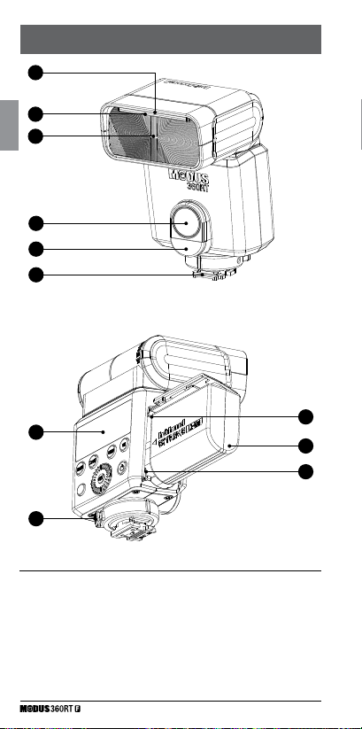
Nomenclature - Body
01
GB
02
03
04
05
06
10
11
01. Catchlight Panel
02. Built-in Wide Panel
03. Flash Head
04. LED Light
05. Optical Control Sensor
06. Hot shoe
07. Battery Compartment
08. Li-ion battery Pack HLX-MD2
09. USB Port
10. LCD Panel
11. Quick Lock ring
6
07
08
09
Page 7
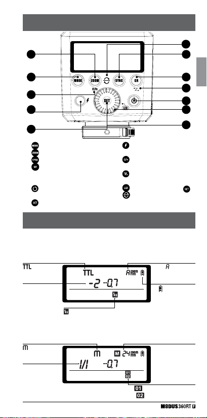
Nomenclature - Control Panel
13 14
12 15
20
19
18
12. - Mode selection button
- Zoom button
13.
– Sync selection button
14.
- Group selection button
15.
15. 01/02 Selection Button in Manual
Mode
- ON/OFF button
16.
17. Select Dial
– Set button
18.
19. Test button & Flash ready
indicator
– Custom function button
20.
(long press)
- Wireless mode button
21.
(long press)
- LED mode (long press )
22.
Reset & open channel
23
buttons (dual long press 13 & 14)
Nomenclature - LCD Panel
On Camera Shooting
• TTL Mode
23
GB
21
16
17
22
:
TTL autoflash
Flash exposure
compensation
• Manual Mode
: Manual flash
Manual flash
output
: High-speed sync
: Auto Zoom
: Battery Status
Manual zoom
focal length
: Standard optical trigger
: Preflash optical trigger
7
Page 8
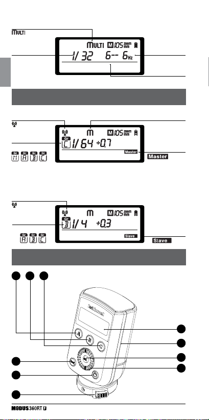
• Multi mode
: Stroboscopic flash
Output power
GB
Radio control shooting
• Master unit
: 2.4GHz
wireless mode
Gr: Group
• Slave unit
: 2.4GHz
wireless mode
Gr: Group
Nomenclature - Viper Mini
A
B C
1
2
Flash frequency
Number of flashes
Flash mode
: Master
: Slave
5
7
3
4
6
8
Page 9
(A) Group A
(B) Group B
(C) Group C
(1) Test - button
(2) ON/OFF - button
(3) SEL - select button
(4) Select Dial
(5) LCD Screen
(6) Quick Lock Ring
(7) Micro USB - firmware update
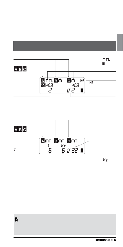
Nomenclature - Viper Mini LCD Screen
GB
Group
: High-speed sync
Flash exposure
compensation
• Multi Mode
Group
: Number
of flashes
• The Viper Mini transmitter is included in the “Modus 360RT Wireless
Kit” and sold separately.
: TTL
: Manual
Flash mode
Manual output
power
Output power
: Flash
frequency
9
Page 10

Getting Started
2
GB
What’s in the Modus 360RT?
1. Modus 360RT Speedlight
2. Mini Stand
3. Li-ion Battery Pack
4. Battery Charger
What’s in the Modus 360RT Wireless Kit
1. Modus 360RT Speedlight
2. Mini Stand
3. Li-ion Battery Pack
4. Battery Charger
5. Micro USB Cable
Battery and Charger
The Modus 360RT uses a lithium ion battery HLX-MD2 and it must be
charged before use
• Use only the MD2 charger to charge the battery
• Remove battery from charger when charging is finished and
disconnect charger from mains. A fully charged battery will offer more
than 400 flashes at full power and even more when power level is
reduced. The composition and construction of the MD2 battery pack
offers very reliable and fast refresh time for the Speedlight.
• How to store the battery
When not in use remove battery from the charger or the Speedlight
and store battery in a cool and dry place. Exposing the battery to higher
temperature can shorten the lifetime of the battery. Store the battery
almost empty (one bar in the battery level indicator) when not used for
a long period of time. For optimum battery life use battery regularly and
if not used for more than 6 months charge the battery fully and use it
with the Modus 360RT until the battery level is down to 1 bar again
before storage.
5. Micro USB Cable
6. Protection Case
7. Instruction Manual
6. Protection Case
7. Instruction Manual
8 Viper Mini Transmitter
9. 2 x AA Batteries
• Battery Lifetime
The lifetime of a rechargeable battery is limited. The capacity will drop
progressively with use and age of battery pack. Replace the battery
pack when the flash cycle time becomes longer or the number of
10
Page 11

flashes reduces noticeably. The battery lifetime can vary substantially
depending on storage, operation conditions and exposure to unsuitable
environmental conditions.
Caution
• Do not short circuit the battery
• Do not drop battery into water or fire
• Do not drop or dismantle or subject the batteries to strong impact or
continuous mechanical shock
• Stop using the battery if the battery has any signs of damage or bulging
to housing and dispose of battery in accordance with the appropriate
local regulations
• How to charge the battery
The HLX-MD2 battery must be charged before use. Use only the
supplied MD2 charger to charge the battery. Connect the MD2 charger
to a USB adapter (min 5V 2 Amp) with the supplied Micro USB
Cable. To start the charge insert the HLX-MD2 battery into the MD2
charger and the red LED bar will start to illuminate, indicating that the
battery is charging. Green LED bar indicates full charge. Remove the
battery from charger when fully charged.
• Fitting and Removing the Battery
1. To fit the battery, push the battery
compartment cover downward
and open it.
2. According to the triangle sign on
the battery pack, insert it into the
compartment.
3. Now close the compartment
Battery
GB
11
Page 12
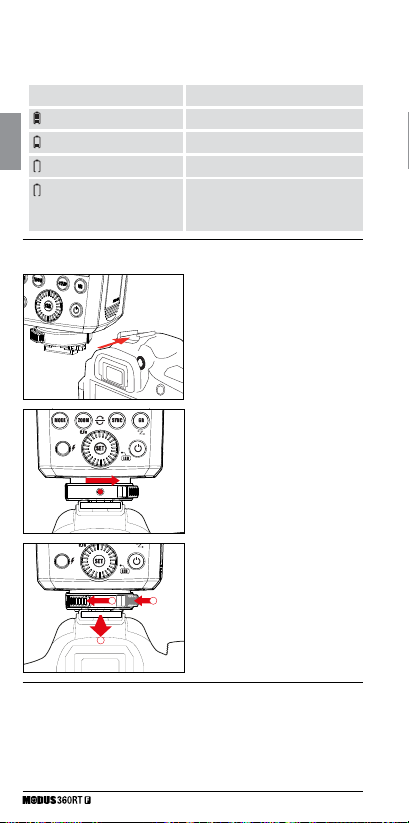
• Battery Level Indication
Check the battery level indication on the LCD panel to see the
remaining battery level.
Battery Level indication
2 bars
GB
1 bar
no bar
no bar “Flashing”
Status
Full
Some remaining power
Low
The battery level is going to run out
immediately. Please recharge the
battery as soon as possible.
Attaching to Camera
1. Attach the Speedlight to the
camera. Slip the flash’s mounting
foot into the camera’s hotshoe
all the way.
2. Secure the Speedlight. Rotate
the lock ring to the right until it
clicks into position.
3. Detach the Speedlight:
a) Push the release button.
b) Rotate the lock ring to
the left until it is loosened.
c) Slide the speedlight off the
a
b
camera hotshoe
c
Power Management
Long press the Power button to power the flash unit on or off.
• Used on camera or as a master flash, it will turn the power off
automatically after a certain period (approx. 90 seconds) of idle use,
when the camera is in sleep mode.
12
Page 13

Pressing the camera shutter halfway or pressing any flash button will
wake up the flash unit.
• Used as a slave flash, it will enter sleep mode after approx. 60
minutes. Pressing any flash button will wake up the speedlight.
• Disabling Auto Power Off function is recommended when the flash
is used off camera. (See C.Fn-St page 28)
Flash Mode
3
This flash has three flash modes: TTL, Manual (M), and MULTI
(Stroboscopic). If camera shooting mode is set to fully automatic, some
modes may not be available.
Flash Mode – TTL Autoflash
In TTL mode, the camera and the flash will work together to calculate
the correct exposure for the subject and the background. In this mode,
multiple TTL functions are available: FEC, HSS, second curtain sync,
etc. These can be controlled with the Modus 360RT or from the camera
directly.
Press <MODE> Mode Selection Button to enter TTL mode. The LCD
panel will display <TTL>.
• Press the camera release button halfway to focus.
• When the shutter button is fully pressed, the flash will fire a preflash
that the camera will use to calculate exposure and flash output, the
instant before the photo is taken.
TTL / M / Multi
• Press < MODE > Mode Selection
Button and the flash mode will
display on the LCD panel one by
one with each button pressing
13
GB
Page 14
• < > FEC: Flash Exposure Compensation
With FEC function, this flash can adjust from -3 to +3 in 1/3rd stops.
It is useful in situations where minor adjusting of the TTL system is
needed based on the environment.
GB
< > High-Speed Sync
On the camera Flash Function Setting Menu set <SYNC> to Auto FP
< HSS > The HSS Icon < > -is switched ON on the Modus 360RT
display.
< > Second-Curtain Sync (Rear-Curtain Sync)
On the camera Flash Function Setting Menu set <SYNC> to Second
Curtain.
The Second Curtain sync icon < > is activated ON on the Modus
360RT display.
To Revert to normal first curtain sync, select first curtain in the
<SYNC> section of the Flash Function settings menu.
• With high-speed sync, the faster the shutter speed, the shorter the
effective range.
• Try to avoid using high-speed sync flash, to extend the flash tube’s
lifetime.
• Over-temperature protection may be activated after 15 consecutive
high-speed flashes.
• MULTI Flash mode cannot be set in high-speed sync mode.
• LCD will display “Hi” (blinking for 3 sec.) when flash output is up
to maximum value. If the photo is underexposed, adjust camera
parameters accordingly.
• LCD will display “Lo” (blinking for 3 sec.) when flash output is
at minimum value. If the photo is overexposed, adjust camera
parameters accordingly.
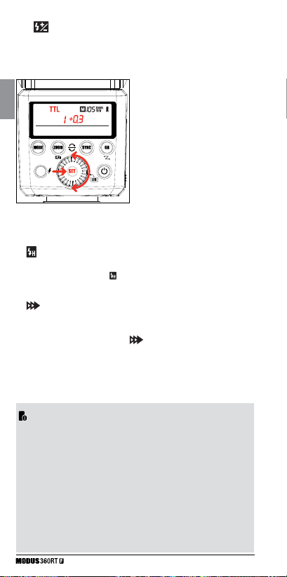
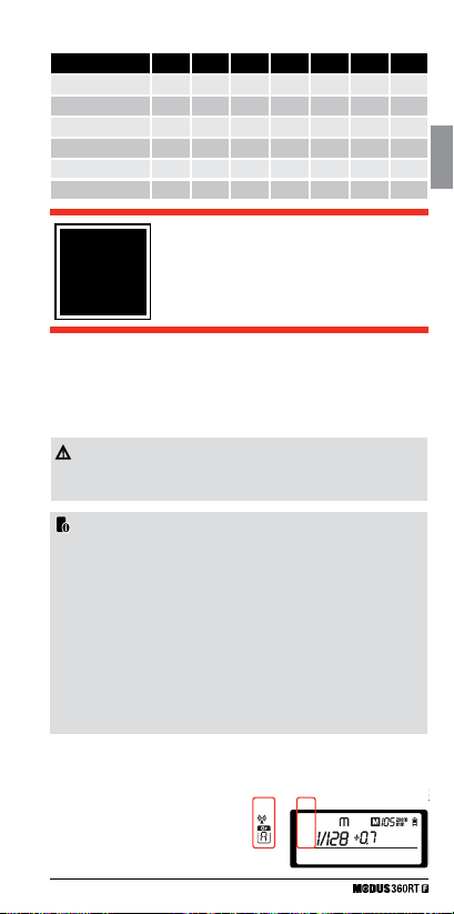
Setting FEC:
1 Press the <SET> Button and the
flash exposure compensation
amount will be highlighted on the
LCD panel
2 Turn the Select Dial to set the
amount.
● “0.3”means 1/3 step, “0.7”means
2/3 step.
● To cancel the flash exposure
compensation, set the amount
to “0”.
3 Press < SET > button again to
confirm the setting.
14
Page 15
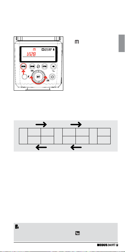
Flash Mode – Manual Flash
The flash output is adjustable from 1/1 full power to 1/128th power
in 1/3rd stop increments. To obtain a correct flash exposure, use a
handheld flash meter to determine the required flash output.
1. Press < MODE > button so that
> is displayed
<
2. Turn the Select Dial to choose a
desired flash output amount
• In high-speed sync mode, the
adjustable flash range is 1/16~1/1
• Flash Output Power Range
The following table makes it easier to see how the stop changes in terms of
f/stop when you increase or decrease the flash output. For example, when
you decrease the flash output: 1/2, 1/2-0.3, or 1/2-0.7, or increase the flash
output:1/2, 1/2+0.3, 1/2+0.7, 1/1.
1/1-0.3 1/2-0.3 ------1/1-0.7 1/2-0.7
1/1 1/2 1/4
1/2+0.7 1/4+0.7 ------1/2+0.3 1/4+0.3
• Optical O1- Standard optical wireless triggering
Remove the Modus360RT from the camera hot shoe. Set it to manual mode
and press the <GR> button to switch on O1. With this function, the flash will
be triggered optically and will fire synchronously when a second main flash
fires. The second main flash is typically also in Manual mode and is on the
camera hot shoe. The off camera flash in O1 and the main flash must have a
clear optical path between them. This helps create multiple lighting effects.
• Optical O2 - Preflash optical wireless triggering
Remove the Modus360RT from the camera hot shoe. Set it to manual mode
and press the <GR> button to switch on O2. With this function, the flash will
be triggered optically and will fire synchronously when a second main flash
fires. The second main flash is typically in TTL mode and is on the camera
hot shoe. The off camera flash in O2 and the main flash must have a clear
optical path between them. This helps create multiple lighting effects.
• O1 and O2 optic triggering is only available in M manual flash mode.
• Press button <SYNC> to activate the “
mode.
HSS” when in O1/O2
15
GB
Page 16
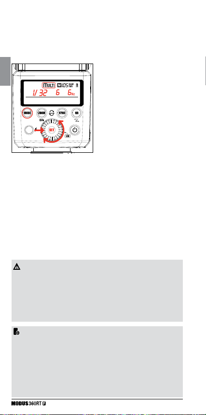
Flash Mode: MULTI Flash (stroboscopic)
With stroboscopic flash, a rapid series of flashes is fired. It can be used
to capture multiple images of a moving subject in a single photograph.
You can set the firing frequency (number of flashes per sec. expressed
as Hz), the number of flashes, and the flash output power.
GB
• Calculating the Shutter Speed
During stroboscopic flash, the shutter remains open until the firing
stops. Use the formula below to calculate the shutter speed and set it
on the camera.
1 Press <MODE> button so that
<Multi> is displayed.
2 Turn the Select Dial to choose a
desired flash output.
3 Set the flash frequency and flash
times.
• Press the <SET> Button to select
the flash frequency. Turn the Select
Dial to set the number.
• Press the <SET> Button again to
select the flash times. Turn the
Select Dial to set the number.
• Press <SET> to lock selection.
• Number of Flashes / Flash Frequency = Shutter
Speed
For example, if the number of flashes is 10 and the firing frequency is
5 Hz, the shutter speed should be at least 2 seconds.
• To avoid overheating and deteriorating the flash head, do not use
stroboscopic flash more than 10 times in succession
• After 10 times, allow the Speedlight to rest for at least 15 minutes.
If you try to use the stroboscopic flash more than 10 times in
succession, the firing might stop automatically to protect the
flash head. If this happens, allow at least 15 minutes’ rest for the
Speedlight.
• Stroboscopic flash is most effective with a highly reflective subject
against a dark background
• Using a tripod and a remote control is recommended.
• A flash output of 1/1 and 1/2 cannot be set for stroboscopic flash
• Stroboscopic flash can be used with “bulb”
16
Page 17
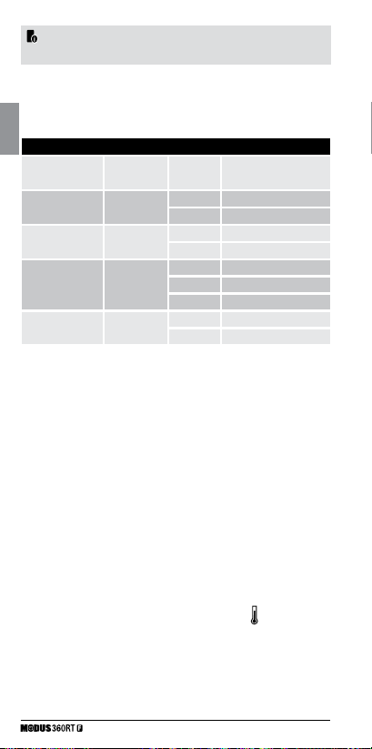
• Maximum Stroboscopic Flashes:
Flash output Hz 1 2 3 4 5 6-7 8-9
1/4 6 3 2 2 2 2 2
1/8 14 14 6 4 3 3 3
1/16 30 30 30 20 10 8 5
1/32 60 60 60 50 50 40 12
1/64 90 90 90 80 80 70 60
1/128 90 90 90 90 90 90 80
Wireless Flash
Photography:
4
You can easily create various lighting effects using the wireless 2.4GHz
control function. The system is designed so that the settings of the
“Master” attached to the camera are automatically applied to the wireless
slave Speedlights. Up to three slave groups can work in TTL / M / Multi
or OFF mode
• If the camera’s is set to fully automatic, some modes may not be
available.
• In this user manual, “Master unit” refers to the flash on a camera and
“Slave unit” refers to an off camera flash controlled wirelessly from
the master unit.
• The “Modus 360RT” as a “Master unit” can control “Slave units”
wirelessly. “Slave units” can be “Modus 360RT” or “Modus 600RT”
speedlights, or flashguns fitted to “Viper TTL” or “Captur receivers”.
• The “Modus 360RT” as a “Slave” unit can be controlled wirelessly
from a “master unit”. A “Master unit” can be a “Modus 360RT” or a
“Modus 600RT” speedlight; a “Viper TTL” or a “Viper Mini” transmitter;
or a “Captur transmitter”, “Module Pro” or “Module Timer”.
• The “Master” can control multiple slave units in the same group or in
separate groups.
(2.4GHz) Control
GB
Wireless Settings
You can switch between normal
flash and wireless flash. For
normal flash shooting, be sure
to set the wireless setting to OFF
17
Wireless
Flash
ON OFF
Normal Flash
Page 18
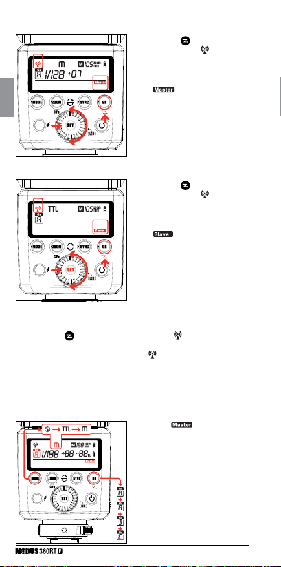
• Master Unit Setting
GB
• Slave Unit Setting
• On Camera Setting
• Press the <
blinking.
• Turn the <Select Dial> until only the <
on the LCD panel.
• Press < SET > button
• “Master” Group - Mode setting
> button for 2 seconds so that < wireless icon > is
• Press the < > button for 2
seconds so that <
icon > is blinking.
• Turn the <Select Dial> until the
<
the LCD panel.
• Press < SET > button
• Press the <
seconds so that <
icon > is blinking.
• Turn the <Select Dial> until the
<
the LCD panel.
• Press < SET > button
wireless icon > is blinking
1) On the “
<GR> button to select groups:
Groups A, B, and C are for the off
camera slave units. The master,
or on camera flash is in Group M.
Then press the < MODE > button
to select the “Flash Mode” (OFF/
TTL/M mode) for that particular
group. Repeat this for all groups to
the desired lighting arrangement.
wireless
icon> is displayed on
> button for 2
wireless
icon> is displayed on
” unit, press the
18
Page 19
2) Press the <MODE> Button for
2 seconds to switch to Multi
(stroboscopic) Group Mode.
3) All groups switch to Multi mode.
4) Press the <MODE> Button for 2
seconds to exit Multi mode.
+ 2 Sec.
• The “Master” Unit is part of group “M”
• The settings selected on the “Master” unit will automatically be set
wirelessly on the corresponding “slave” units.
• You can assign several “Slave” units to the same group- they will all
have the same settings.
• All Four groups, M/A/B/C, can have their modes set independently.
Setting the DCM (Digital Channel Matching)
When they are shipped, the Modus360RT and Viper Mini are set to
a 2.4GHz “open channel” and can be used immediately. To avoid
interference with other flash systems, we recommend to DCM (Digital
Channel Match) your units on to a “closed” channel. DCM also allows
you to integrate other, different, units like the Modus600RT and Captur
range into your set up.
See page 16 for details and how to
set the multi values.
In Multi mode, to switch groups on/
off, press the < Gr > Button to
switch the group on/ off.
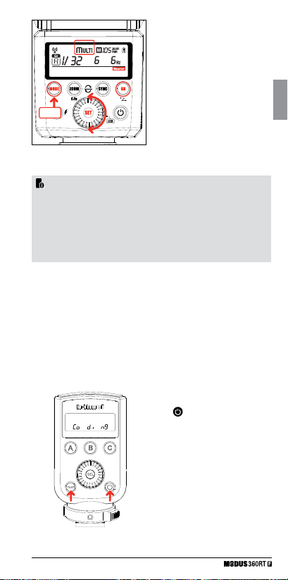
• DCM Master – Viper Mini or Modus 360RT
1. Press and hold the < test > button
while you switch on the unit,
> then release the
<
< test > button. The display will
show Co di ng
GB
19
Page 20

2. If you are not using a Viper Mini as
a master unit, then use a Modus
360RT as the Master unit
• Press and hold the <MODE> while
you switch on the unit <
button >.
GB
• A red LCD will light up and will
show <
• To DCM a Modus360RT as a slave
3. To DCM a Modus360RT as a slave
• Press and hold the < ZOOM >
button while you switch on the unit
pressing <
• A red LCD will light up and will
show <
• If the <
it means that it cannot detect a
master unit to match to.
4. Additional Modus360RT can be
matched as slave units to this
master in the same way. Do not
switch off the master unit until all
slave units have been matched.
• The “Master” unit must be on all the time and show <Co di ng>/
<MASTER> whilst all the “Slaves” are DCM matched
Once all slave units are DCM matched, reboot the master and all slaves
by turning OFF/ON
• Once all devices are DCM matched they will memorise their unique
ID even if power is removed. Therefore you only need to DCM your
set once
• You can DCM match all hahnel wireless devices which share the same
DCM matching system (i.e. Modus 600RT, Modus 360RT, Viper TTL
Transmitter and Receiver, Viper Mini Transmitter, Captur Transmitter
and Receiver, Captur Module Pro, Captur Module Timer.
• If you add more Speedlights or hahnel wireless devices to your set,
then you need to carry out DCM matching again for all of your units.
icon
>
icon > button.
>
> Icon flashes then
20
Page 21
• Modus 360 RT – Reset
> the Modus 360RT
+ 2 Sec.
• To reset <
to factory default settings, press
<ZOOM> & <SYNC> buttons at
the same time and hold for more
than 2 seconds.
• When the Modus 360RT is reset
the DCM is also reset back to
“open channel” and the previous
DCM is lost
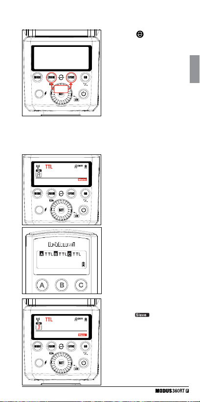
TTL: Fully Automatic Wireless Flash Shooting
• TTL Autoflash Shooting with One Slave Unit
1 Master Unit Setting
• Attach 1st Modus 360RT (or Viper
Mini) to camera and set it as the
master unit. (Page 18)
• Check that <Group> M/A/B/C can
be set to TTL mode independently
2 Slave Unit Setting
• Set 2nd Modus 360RT as the
wireless “
• Set the slave unit to <Group> A.
3 Position of camera and
speedlight
• Position the camera with the master
unit attached and the Modus slave
within radio range
” unit. (Page 18)
GB
21
Page 22

4 Check the flash operation
• Press the master unit’s <Test icon flash> Test Button.
• The “Master” and “Slave” unit will then fire.
M: Wireless Flash Shooting with Manual Flash
This describes wireless using manual flash. You can shoot with a
different flash output setting for each slave unit (firing group). Set all
GB
parameters on the master unit.
1 Master Unit Setting
• Attach 1st Modus 360RT (or Viper
Mini) to camera and set it as the
master unit. (Page 18)
• Check that <Group> M/A/B/C
can be set to Manual mode
independently
2 Setting flash output
• Press <GR> button to select
the group
• Now turn the Select Dial to set
the flash output of this particular
group.
3 Slave Unit Setting
• Set 2nd Modus 360RT as the
wireless “Slave” unit. (Page 18)
• Set the slave unit to <Group> B.
4 Position of camera and
Speedlight
• Position the camera with the master
unit attached and the Modus slave
within radio range
22
Page 23
5 Check the flash operation
• Press the master unit’s <Test icon flash> Test Button.
• The “Master” and “Slave” unit will then fire. Each group fires at the set flash
output power
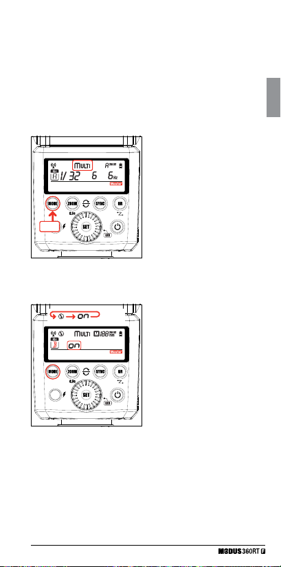
MULTI: Wireless shooting with Multi repeating flash
stroboscopic
This describes wireless using stroboscopic flash. Set all parameters
on the master unit.
1 Master Unit Setting
• Attach 1st Modus 360RT (or Viper
Mini) to camera and set it as the
master unit. (Page 18)
• Long press the <MODE> button
for 2 seconds so that <Multi>
is displayed. Long press the
<MODE> button again for 2
+ 2 Sec.
seconds to exit.
2 Setting flash output/flash
frequency/flash times
• Set the flash output/flash
frequency/flash times in Group
<M> for all groups. (see page 16).
3 Turning ON/OFF each group
• Use the <GR> button to select
groups.
• Press <Mode> button to turn ON/
OFF group M, A, B or C individually
GB
23
Page 24

Wireless Flash
Photography:
5
GB
The Viper Mini transmitter is included in the Modus360RT Wireless
Kit and is available as an accessory also. The Viper Mini is a light
weight 2.4GHz transmitter which allows wireless control of off camera
Modus360RT speedlights when it is fitted to the camera hot shoe.
DCM (Digital Channel Matching)
1. DCM (Digital Channel Matching). Carry out the DCM matching (see
page 19).
2. Set the Modus 360RT to wireless as a Slave Unit - Group A (see
page 18).
3. Press Viper Mini <test> 01 button to confirm that Modus Speedlight
is triggered wirelessly.
Viper Mini group Mode Setting
Press buttons A or B or C to change the <MODE> setting of each
group to <TTL>, <M> manual or <blank> OFF.
Take a test photograph now and the Viper Mini transmitter will send a
wireless signal to each Modus 360RT. The Speedlight will then be set
automatically to the same Viper Mini selected group mode setting.
• The Viper Mini LCD 05 will show the setting of each group
• A group is turned OFF if the LCD is not showing the group
• A group is in Manual mode when <M> is displayed next to the group
• A group is in TTL mode when <TTL> is displayed next to the group
• Each group A , B or C is set independently and it is possible to use
simultaneously different settings for each group (e.g. Group A may be
in <M>, Group B in <TTL> and Group C turned OFF)
using Viper Mini Transmitter
(2.4GHz)
Power Control setting for Manual and TTL FEC
From the Viper Mini transmitter you can adjust the power level and the
FEC of each group.
4. Press <SEL> 03 select button and all three icons <A>, <B> and
<C> will flash.
5. Press one button A or B or C to select which group you want to
adjust the power. Now only the selected group icon <A or B or C>
will flash
24
Page 25
6. Use the adjust dial to set the power output in < M > mode and
FEC in <TTL> mode.
7. Press the <SEL> button to save your selection.
Multi Mode
• Press and hold the < Group A > button to select the Multi mode
< > . Use the < SEL > button, Group Buttons and adjust dial to
set the number of flashes, flash frequency and power output. Press the
< SEL > button again to save selection.
• For more detail on operation of the viper Mini visit www.hahnel.ie
< > High-Speed Sync
On the camera Flash Function Setting Menu set <SYNC> to Auto FP <
HSS > The HSS Icon < > -is switched ON on the Viper display.
< > Second-Curtain Sync (Rear-Curtain Sync)
On the camera Flash Function Setting Menu set <SYNC> to Second
Curtain.
The Second Curtain sync icon < > is activated ON on the Viper
display.
To Revert to normal first curtain sync, select first curtain in the
<SYNC> section of the Flash Function settings menu.
Other Applications
6
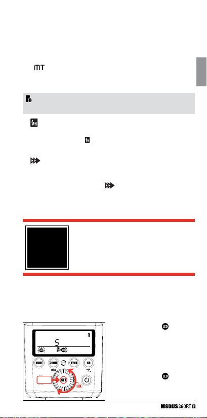
Illuminating for video shooting – LED light
You can use the LED light of the Modus 360RT as a light source
for video shooting. It helps create natural lights and shadows in an
environment with poor lighting and add more 3D effects in video.
> button
> button
+ 2 Sec.
1 Long press < SET /
for more than 2 sec. to enter the
“LED-Menu”.
2 Now short press < SET > button to
turn ON / OFF LED.
3 Use the Select Dial to change the
LED light power from 1 to 5.
4 Long press < SET /
again the exit the “LED – Menu”.
GB
25
Page 26
Auto Focus Assist Beam
In poorly-lit or low-contrast shooting environments, the built-in auto
focus assist LED light will automatically switch on to make it easier to
autofocus. The light beam will light up only when autofocus is difficult
and will switch off as soon as the autofocus is set. If you want to turn
off the auto focus assist beam, set “AF” to “OF” on the C.Fn settings.
GB
• Also check the camera menu settings for “AF Illuminator” and for
“LED” in the flash funtion setting menu.
• If you find the auto focus assist beam does not light up, this is because
the camera has got a correct autofocus.
• The auto focus assist beam does not operate while Continuous AF is
used as the camera focusing mode
• When not attached to the camera, the auto focus assist beam will
not light up.
Bounce Flash
By pointing the flash head toward a wall or ceiling, the flash will bounce
off the surface before illuminating the subject. This can soften shadows
behind the subject for a more natural-looking shot. This is called
bounce flash.
To set the bounce direction, hold the flash head and turn it to
the required angle.
-7-90
270
• If the wall or ceiling is too far away, the bounced flash might be too
weak and result in underexposure.
• The wall or ceiling should be a plain, white color for high reflectance.
If the bounce surface is not white, a colour cast may appear in the
picture.
Catchlight Panel
With the catchlight panel, you can create a catchlight in the subject’s
eyes to add life to the facial expression.
26
Page 27
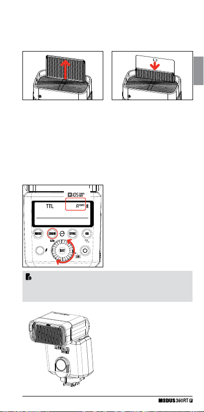
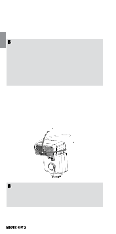
1. Point the flash head upward by 90°
2. Pull out the wide panel. The catchlight panel will come out at the same time
3. Push the wide panel back in
• Push in only the wide panel
• Follow the same procedures as for bounce flash
ZOOM: Setting the Flash Coverage and Using
the Wide Panel
The flash coverage can be set automatically or manually. Use the AP
setting in the C. Fn menu to select the flash head zoom range you
want.
AP OF - AUTO / 24/ 28/ 35/ 50/ 70/ 80/ 105mm
AP ON - AUTO / 16/ 18/ 23/ 33/ 46/ 53/ 69mm
Wide Panel - AP ON - 12mm
Wide Panel - AP OF - 14mm
For Manual Zoom mode, press the
<ZOOM/C.Fn> button.
• Turn the Select Dial to change the
flash coverage
• If < A > is displayed, the flash
coverage will be set automatically
• If you set the flash coverage manually, make sure it covers the lens
focal length so that the picture will not have a dark periphery.
GB
Using the Wide Panel
Pull out the wide panel and place
it over the flash head as shown.
The flash coverage will then be
extended to 12mm or 14mm.
• The catchlight panel will come
out at the same time. Push the
catchlight panel back in.
27
Page 28
• The <ZOOM/C.FN> button will not work.
C.Fn: Setting Custom Functions
The following table lists the available custom functions of this flash.
GB
C.Fn Custom Functions
Custom Function
Signs
St
AF
bL
AP
1. Press the < ZOOM > Button for 2 seconds until C.Fn menu is displayed.
2. Turn the Select Dial to select a Custom Function.
3. Press the <SET> Button and the Setting blinks.
4. Turn the Select Dial to set the desired setting. Pressing the <SET> Button
will confirm the settings.
5. Press the <ZOOM> Button to exit.
Protection Functions
1. Over-Temperature Protection
• To avoid overheating and deteriorating the flash head, do not fire
more than 30 continuous flashes in fast succession at 1/1 full power.
After 30 continuous flashes, allow a rest time of at least 10 minutes
• If you fire more than 30 continuous flashes and then fire more flashes
in short intervals, the inner over-temperature protection function may
be activated and make the recycling time over 10 seconds. If this
occurs, allow a rest time of about 10 minutes, and the flash unit will
then return to normal
• When the over-temperature protection is active, <
the LCD display
Function
Auto
Power off
AF - assi st
beam
Backlighting
control
Focus
Range
Setting No.
ON
OF
1 - 5
OF
10
OF
ON
ON
OF
Setting & Description
Auto Power off enable
Auto Power off disable
AF Assist beam level
AF Assist beam disable
Off in 10 sec .
Always O ff
Always lighting
Auto & 16 - 69mm
Auto & 24 - 105 mm
> is shown on
Number of flashes that will activate over temperature protection:
28
Page 29
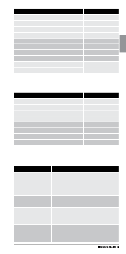
Power Output Level Number of Flashes
1/1
1/2 + 0.7
1/2 + 0.3
1/2
1/4 (+0.3, +07)
1/8 (+0.3, +07)
1/16 (+0.3, +07)
1/32 (+0.3, +07)
1/64 (+0.3, +07)
1/128 (+0.3, +07)
Number of flashes that will activate over-temperature protection in
high-speed sync triggering mode:
Power Output
1/1
1/2 (+0.3, +07)
1/4 (+0.3, +07)
1/8 (+0.3, +07)
1/16 (+0.3, +07)
1/32 (+0.3, +07)
1/64 (+0.3, +07)
1/128 (+0.3, +07)
2. Other Protections
• The system provides real-time protection to secure the device and
your safety. The following lists prompts for your reference:
Prompts LCD Panel
E1
E2
E3
E9
Meaning
A failure occurs on the recycling system so that
the flash cannot fire
Please restart the flash unit. If the problem still
exists, please send this product to a maintenance
centre.
The system gets excessive heat. Please allow a
rest time of 10 min.
The voltage on two outlets of the flash tube is too
high. Please send this product to a maintenance
centre.
Some error occurred during the upgrading
process. Please use the correct firmware upgrade
method.
29
30
40
50
60
100
200
300
500
1000
Times
15
20
30
40
50
GB
Page 30

Technical Data
Model MODUS 360RT
• Type
Compatible Cameras
Guide No.
GB
(1/1 output @ 105mm)
Flash Coverage
Flash duration
• Exposure Control
Exposure Control System
Flash Exposure
Compensation (FEC)
Sync mode
Multi Flash
• Wireless Flash (2.4 GHz radio transmission)
Wireless flash function
Controllable Groups
Transmission Range
(approx.)
Channels
• Auto Focus Assist Beam
Effective range (approx.)
• LED Light
Centre luminance
Intensity
Continuous lighting time
Colour temperature
• Power Supply
Lithium-Ion battery
Recycle time
Fujifilm Cameras
36 (m ISO 100)
24 to 105mm & 16 to 69mm
• Auto zoom (flash coverage set automatically to
match the lens focal length and image size)
• Manual Zoom
• Swinging/ tilting flash head (bounce flash): 0 to
270º horizontally and -7º to 90º vertically
1/350 to 1/20000 seconds
TTL autoflash and manual flash
TTL FEC: +/- 3 stops in 1/3 stop increments
High-speed sync (up to 1/8000 seconds),
first-curtain sync, and second curtain sync
Provided (up to 90 times, 99Hz)
Master, Slave, Off
M, A, B and C
Typical 50m
Digital Channel Matching
Center: 0.6-4m
Periphery: 0.6-2.5m
Approx. 440 lx @ 0.5m
110 lx @ 1.0m
Approx. 11 Hours
Approx. 5600 K
7.2V/ 2000 mAh
0.1s-1.7s
30
Page 31

Full power flashes
Power saving
• Sync Triggering Mode
• Dimensions
H x W x D
Weight without battery
Weight with battery
2.4GHz Wireless frequency
range
Max. Transmitting Power
of 2.4GHz Wireless
Troubleshooting
If there is a problem, refer to this Troubleshooting Guide.
The Camera Flash does not fire.
• The camera flash is not attached securely to the camera.
Attach the flash mounting foot securely to the camera.
• The electrical contacts of the Camera Flash and camera are dirty.
Clean the contacts.
• The flash ready indicator does not light up after a long wait,
check whether the battery power is enough. If the battery power is
low, < > will appear and blink on the LCD panel. Please charge the
battery immediately.
The power turns off by itself.
• After 90 seconds of idle operation, auto power off took effect if the flash
is set as master.
Press the shutter button halfway or press any flash button to wake up.
• After 60 minutes of idle operation, the flash unit will enter sleep mode
if it is set as slave.
Press any flash button to wake up.
Auto zoom does not work.
• The camera flash is not attached securely to the camera.
Attach the flash mounting foot to the camera.
More than 400
Power off automatically after approx. 90 seconds
of idle operation. (60 minutes if set as slave)
Hotshoe, optical triggering
150 x 64 x 50mm
220g
300g
2413.0 MHz - 2464.5MHz
5dbm
GB
31
Page 32

• The Wide Panel is in use or partially pulled out
Using the Wide panel disables Auto zoom and locks the zoom at 14 -
12mm. Check that Wide Pannel is pushed into housing all the way.
• The Zoom may be set to Manual Zoom
Change Speedlight zoom setting to Auto zoom.
GB
The flash exposure is underexposed or overexposed.
• You used high-speed sync.
With high-speed sync, the effective flash range will be shorter. Make
sure the subject is within the effective flash range.
• You used Manual Flash mode.
Set the flash mode to TTL or modify the flash output.
Photos have dark corners or only parts of the target subject
are illuminated.
• The focal length of lens exceeds the flash coverage.
Check the flash coverage you set. This flash unit has coverage
between 24 and 105mm and between 16mm and 69mm. Pull the wide
panel out to extend the flash coverage.
Firmware Upgrade
This flash supports firmware upgrade through the USB port. Update
information will be released on our official website www.hahnel.ie
Checking the version:
Hold down the <Test icon> button and the turn the flash on. Then,
the firmware update version (e.g. Version 2.0 will read U-2.0) will be
displayed on the LCD panel.
• Use the included USB cable to do the firmware update.
• For up to date compatibility of all camera models check www.hahnel.ie
32
Page 33

Maintenance
• Shut down the device immediately should abnormal operation be
detected
• Avoid sudden impacts and the product should be cleaned regularly
• It is normal for the flash tube to be warm when in use. Avoid
continuous flashes if unnecessary
• Maintenance of the flash must be performed by our authorised
maintenance department which can provide original accessories
• This product, except consumables e.g. flash tube, is supported with
a one-year warranty
• Unauthorised service will void the warranty
• If the product has malfuctioned or has been damaged by water do
not use until it is repaired by a professional
• Changes made to the specifications or designs may not be reflected
in this manual
• This Product complies with the EU Radio Equipment Directive
2014/53/EU.
• For compliance data visit www.hahnel.ie
GB
33
Page 34

GB
Wireless Speedlight
for Fujifilm
All product specifications subject to change without notice E.&O.E.
All brands, trademarks and registered trademarks are the property of
their respective holders. Copyright © hähnel industries Ltd, Ireland.
A product of hähnel industries ltd., Ireland. Made in China
Änderung und Irrtum vorbehalten.
Toutes les spécifications du produit sont sous réserve de
modifications S.E.O.O.
www.hahnel.ie
Rev: 01/19
34
Page 35

Kabelloses Blitzgerät
für Fujifilm
DE
German
1
Page 36

Vorwort
Vielen Dank für den Kauf der Modus 360RT.
• Bevor Sie das Gerät in Betrieb nehmen, sollten Sie diese
Bedienungsanleitung lesen.
• Lesen Sie diese Bedienungsanleitung in Verbindung mit der
Bedienungsanleitung Ihrer Kamera.
DE
Konventionen & Voraussetzungen
• Die Bedienungsanleitung geht davon aus, daß alle Geräte inkl. der
Kamera eingeschaltet sind.
• Seitennummern der Referenz sind gekennzeichnet mit (S. **)
Das Warnsymbol weist daraufhin, Probleme bei den
•
Aufnahmen zu vermeiden
Das Notiz-Symbol weist auf ergänzende Informationen hin
•
2
Page 37

Contents
1 Einleitung
• Sicherheitshinweise und Warnungen 4
• Bezeichnungen Gehäuse
• Systemsteuerung
• Schalttafel
• LCD-Display
• Bezeichnungen Gehäuse - Viper Mini
• Schalttafel
• LCD-Display
2 Erste Schritte
• Modus 360RT - Inhalt der Box 10
• Kabellos-Kit – Inhalt der Box
• Akku und Ladegerät
• Anbringen an der Kamera
• Power Management
3 Blitz-Modus – TTL / M / Multi
• Blitz-Modus - TTL Autoflash 13
• FEC (Blitzbelichtungskorrektur)
• HSS (Hochgeschwindigkeits-Synchronisation)
• Verschlussvorhang
• Blitzmodus - Manueller Blitz
• Blitz-Ausgangsleistungsbereich
• Optische O1 Einstellung Sekundäreinheit
• Optische O2 Einstellung Sekundäreinheit
• Blitzmodus - Multi: Stroboskopischer Blitz
4 Kabellose Blitz-Fotografie: (2,4 GHz) Steuerung
• Kabellose Einstellungen 17
• Einstellungen der Master-Einheit 18
• Einstellungen der Slave-Einheit
• Auf der Kamera (keine drahtlose Einstellung)
• Master “Group-Mode” Einstellung
• DCM (Digitale Kanalanpassung)
• Master - Viper Mini oder Modus 360RT
• Slave - Modus 360RT
• Modus 360RT - Zurücksetzen
• TTL - Vollautomatische kabellose Blitzaufnahmen
• M: Kabellose Blitzaufnahmen mit manuellem Blitz
• MULTI: Kabellose Blitzsaufnahmen mit sich wiederholenden
stroboskopischem Blitz
3
6
7
7
DE
8
9
10
10
12
12
14
14
14
15
15
15
15
16
18
18
18
19
19
20
21
21
22
23
Page 38

5 Kabellose Blitz-Fotografie: (2,4 GHz) mit Viper Mini
Sender
• DCM (Digitale Kanalanpassung) 24
• Viper Mini Gruppenmodus-Einstellung
• Gruppeneinstellung Leistungsregelung für manuellen Betrieb
und TTL FEC
• Multi-Modus 2
• Synchronisations Modi
DE
6 Andere Anwendungen
• LED-Licht 25
• Auto-Fokus Hilfsstrahl
• Indirektes Blitzen
• Catchlight-Scheibe
• Zoom - Einstellung des Leuchtwinkels und Verwendung der
Weitwinkel-Streuscheibe
• C.Fn – Einstellung benutzerdefinierter Funktionen
• Schutzfunktionen
• Technische Daten
• Fehlerbehebung
• Firmware aktualisieren
• Wartung
Einführung
1
Warnhinweise:
Die Nichtbeachtung der Anweisungen kann zu Tod oder
schweren Körperverletzungen führen. Beachten Sie die folgenden
Vorsichtsmaßnahmen zur Vermeidung von Feuer, Überhitzung, Auslaufen
von Chemikalien, Explosionen und Stromschlägen:
• Führen Sie keine metallischen Fremdkörper in die elektrischen
Kontakte des Produkts, des Zubehörs, Anschluss Kabel, etc. ein.
• Verwenden Sie keine Batterien, Stromquellen oder Zubehör, das nicht
in der Bedienungsanleitung angegeben ist. Verwenden Sie keine
deformierten oder veränderten Batterien oder das Gerät, falls es
beschädigt ist.
• Verursachen Sie keinen Kurzschluss, nehmen Sie das Gerät oder die
Batterien nicht auseinander und nehmen Sie keine Veränderungen vor.
Erhitzen oder löten Sie nicht die Akkus.
• Lagern Sie die Akkus nicht zusammen mit metallischen Gegenständen.
4
24
24
5
25
26
26
26
27
28
28
30
31
32
33
Page 39

Setzen Sie die Akkus nicht Feuer oder Wasser aus. Setzen Sie die
Akkus keinen starken Stößen oder kontinuierlichen mechanischen
Schocks aus.
• Legen Sie Akkus nicht in die Mikrowelle, Kochgeräte oder HochdruckBehälter.
• Verwenden Sie das Gerät nicht in der Nähe von brennbarem Gas.
• Richten Sie den Blitz nicht auf Fahrer eines Autos oder anderer
Fahrzeuge.
• Nehmen Sie das Gerät nicht auseinander und nehmen Sie keine
Veränderungen vor. Bauteile unter Hochspannung können elektrische
• Schläge verursachen. Sollten Sie das Gerät fallen lassen und das
Gehäuse zerbricht, berühren Sie nicht die Bauteile. Es besteht die
Möglichkeit eines elektrischen Schlags.
• Lagern Sie das Gerät nicht an staubigen oder feuchten Orten oder
Orten mit Ölnebel. Lagern Sie Akkus nicht im Ladegerät .
• Bewahren Sie Akkus und sonstiges Zubehör außerhalb der Reichweite
von Kindern und Säuglingen auf.
• Lassen Sie das Gerät oder die Akkus nicht ins Feuer oder Wasser
fallen.
• Setzen Sie das Gerät oder die Akkus nicht extremen Temperaturen
(unter 0ºC oder über 40ºC) oder starker Sonneneinstrahlung aus.
• Die Temperatur der Akkus sollte während des Ladevorgangs oder
des Gebrauchs nicht über 60ºC/140ºF steigen. Sollte die Temperatur
darüber hinaus steigen, beenden Sie die Nutzung und brechen Sie den
Ladevorgang sofort ab.
• Verwenden Sie keine Verdünner, Benzol oder andere organische
Lösungsmittel zur Reinigung des Geräts.
Vorsicht:
• Die Nichtbeachtung der nachstehenden Anweisungen kann zu
schweren. Körperverletzungen oder Sachschäden führen
• Wird das Gerät über einen längeren Zeitraum nicht benutzt, achten Sie
darauf, die Akkuz zu entnehmen.
• Bei der Entsorgung der Akkus isolieren Sie die elektrischen Kontakte
mit Klebeband. Kontakt mit anderen metallischen Objekten oder
Batterien kann Feuer oder eine Explosion verursachen. Entsorgen Sie
Batterien gemäß den maßgeblichen Vorschriften.
• Lassen Sie das Gerät oder die Akkus nicht im Kofferraum oder auf
dem Armaturenbrett eines Fahrzeugs oder in direktem Sonnenlicht, da
die Überhitzung zu Verbrennungen, Feuer, Explosion oder Austritt von
Chemikalien führen kann.
• Lösen Sie den Blitz nicht aus, wenn der Blitzkopf (Licht emittierende
Einheit) in Berührung mit einem menschlichen Körper oder einem
anderen Objekt ist, da das Risiko von Verbrennungen und Feuer
besteht.
• Lösen Sie den Blitz nicht in der Nähe der Augen aus. Halten Sie das
Blitzgerät mindestens 1m (3,3 Fuß) vom Gesicht entfernt. Es kann
Schmerzen verursachen oder die Augen schädigen. Indirekte Blitze, um
vvdie Lichtstärke zu reduzieren, sind ebenfalls zu empfehlen.
5
DE
Page 40

Bezeichnungen Gehäuse
01
02
03
DE
04
05
06
10
11
01. Catchlight Scheibe
02. Integrierte Weitwinkel-Streus
cheibe
03. Blitzkopf
04. LED-Licht
05. Optischer Kontrollsensor
06. Zubehörschuh
07. Batteriefach
08. Li-Ionen-Akku HLX-MD2
09. USB-Anschluss
10. LCD-Display
11. Schnellverschluss
6
07
08
09
Page 41

Bezeichnungen - Display
13 14
12 15
20
19
18
12. - Auswahl-Taste
- Zoomtaste
13.
- Sync-Auswahltaste
14.
- Gruppe Auswahltaste
15.
15. 01/02 Auswahltaste im manuellen
Modus
- AN/AUS Schalter
16.
17. Wählscheibe
- Auswahl-Taste
18.
Test-Taste/ Blitzbereitschafts-
19.
anzeige
20.
- Benutzerdefinierte Funktion-
staste (langes Drücken)
- Funkmodus-Taste (langes
21.
Drücken)
- LED-Modus (langes
22.
23
)
Drücken
Reset & Open Channel
Buttons (doppeltes langes
Drücken 13 & 14)
Bezeichnung – Display
Auf der Kamerafotos
• TTL- Modus
23
21
16
DE
17
22
:
TTL Autoflash
Blitzbelichtungskorrektur
: Hochgeschwindigkeits -
Synchronisation
• Manuelles Blitzen
: Manuelles
Blitzen
Manuelle
Blitzleistung
: Optischer Standardauslöser
7
: Auto - Zoom
: Akkuladestand-
sanzeige
Fokus Entfernung
: Vorblitz Optisch Auslöser
Page 42

• Multi-Modus
: sich
wiederholender
stroboskopischer
Blitz-Ausgangsleistung
DE
Funkkontrolle Aufnahme
• Master- Blitzgerät
: kabelloser
Modus
Gr: Gruppe
• Slave unit
: kabelloser
Modus
Gr: Gruppe
Bezeichnungen - Viper TTL Mini Sender
A
B C
Blitzfrequenz
Anzahl der Blitze
Blitzmodus
: Master
: Slave
5
7
1
2
6
8
3
4
Page 43

(A) Gruppe A
(B) Gruppe B
(C) Gruppe C
(1) Test-Taste
(2) ON/OFF - switch
(3) SEL - Auswahltaste
(4) Cadran
(5) LCD-Display
(6) Schnellverschluss
(7) Mikro USB - Firmware-
Akualisierung
Bezeichnungen - Viper TTL Mini Bildschirm
Gruppe
Blitzbelichtungskorrektur
• Multi-Modus
Gruppe
: Anzahl der
Blitze
: Hochgeschwind-
igkeits-Synchro-
Manuelle Blitzleistung
Blitz-Ausgangsleistung
: Blitzfrequenz
: TTL
: Manueller
Blitzmodus
nisation
DE
• Der Viper Mini ist im Modus 360RT Wireless Kit enthalten sowie
separat erhältlich
9
Page 44

Erste Schritte
2
Was ist im Modus 360RT Kit enthalten?
1. Modus 360RT Blitzgerät
DE
2. Mini-Ständer
3. Lithium-Akku
4. Akkuladegerät
Was ist im Modus 600RT Wireless Kit enthalten?
1. Modus 360RT Blitzgerät
2. Mini-Ständer
3. Lithium-Akku
4. Akkuladegerät
5. Micro-USB Kabel
Akku und Ladegerät
Das Modus-360RT nutzt einen Lithium-Ionen Akku HLX-MD2, der vor
Gebrauch aufgeladen werden muss.
• Verwenden Sie nur das MD2 Ladegerät zum Aufladen des Akkus
• Entfernen Sie den Akku aus dem Ladegerät, wenn der Ladevorgang
abgeschlossen ist und trennen Sie das Ladegerät vom Stromnetz. Ein
voll aufgeladener Akku leistet ca. 400 Blitze bei voller Leistung und
noch mehr bei reduzierter Leistung. Die Zusammenstellung und der
Aufbau des Akkupacks MD2 ermöglicht eine zuverlässige und schnelle
Wiederaufladung des Speedlight-Blitzgeräts.
• Korrekte Lagerung des Akkus
Wenn nicht in Gebrauch, nehmen Sie den Akku aus dem Ladegerät
oder dem Speedlight-Blitzgerät und aufbewahren Sie ihn an einem
kühlen und trockenen Ort auf. Die Lebensdauer des Akkus kann
durch zu hohe Temperaturen verkürzt werden. Wenn Sie den Akku für
längere Zeit nicht verwenden, lagern Sie ihn in fast leerem Zustand
(ein Balken in der Akkuanzeige). Für eine optimale Lebensdauer des
Akkus benutzen Sie ihn regelmäßig. Bei Nichtgebrauch für mehr als 6
Monate laden Sie den Akku vollständig auf und benutzen Sie ihn vor der
Lagerung mit der Modus-600RT, bis die Batterie bis zu einem Balken
entleert ist.
• Lebensdauer des Akkus
When Die Lebensdauer eines Akkus ist begrenzt. Die Kapazität
sinkt fortschreitend mit Gebrauch und Alter des Akkus. Ersetzen Sie
den Akku, wenn der Blitz-Zyklus länger wird oder sich die Anzahl
5. Micro-USB Kabel
6. Schutzhülle
7. Bedienungsanleitung
6. Schutzhülle
7. Bedienungsanleitung
8. Viper Mini Sender
9. 2 x AA-Akkus
10
Page 45

der Blitze merklich verringert. Die Lebensdauer des Akkus kann je
nach Lagerung, Belastung und Beeinträchtigung durch ungeeignete
Bedingungen erheblich variieren.
Achtung
• Verursachen Sie keinen Kurzschluss des Akkus
• Lassen Sie den Akku nicht in Wasser oder Feuer fallen
• Lassen Sie den Akku nicht fallen, nehmen Sie den Akku nicht
auseinander oder setzen Sie ihn keinen starken oder kontinuierlichen
mechanischen Schocks aus
• Verwenden Sie den Akku nicht mehr, wenn er Anzeichen von
Beschädigung aufweist oder sich die Ummantelung wölbt, und
entsorgen Sie ihn gemäß der lokalen Vorschriften
• So wird der Akku geladen
Der HLX-MD2 Akku muss vor dem Gebrauch aufgeladen werden.
Verwenden Sie das mitgelieferte MD2 Ladegerät, um den Akku zu
laden. Schließen Sie das MD2Ladegerät mit dem mitgelieferten
Micro-USB Kabel an einen USB-Adapter (min. 5V 2 Amp.) an. Um den
Ladevorgang zu beginnen, stecken Sie den HLX-MD2 Akku in das
Ladegerät MD2, die rote LED-Leiste beginnt zu leuchten. Dies zeigt,
dass der Akku geladen wird. Grüne LED-Leiste zeigt volle Ladung an.
Nehmen Sie den Akku aus dem Ladegerät, sobald er voll aufgeladen
ist..
• Einsetzen und Entfernen des Akkus
1. Um die Batterie einzusetzen,
schieben Sie die Abdeckung des
Batteriefachs zum Öffnen nach
unten.
2. Schieben Sie den Akku gemäß dem
dreieckigen Symbol in das Fach
bis ein weißer Clip die Batterie mit
einem Klickgeräusch einrasten
lässt..
DE
3. Schließen Sie jetzt das Batteriefach
11
Page 46

• Akkustandsanzeige
Überprüfen Sie die Akkustandsanzeige auf dem LCD-Display, um die
verbleibende Akkuladung zu sehen.
Akkustandanzeige
2 Balken
1 Blaken
keine Blaken
DE
keine Blaken “Blinken”
Staut
Voll
etwas restliche kraft
niedrig
Niedriger Ladestand, bitte
wiederaufladen
Anbringen an der Kamera
b
c
Power Management
Halten Sie die Ein- / Aus-Taste gedrückt, um das Blitzgerät ein- oder
auszuschalten.
• Wenn auf der Kamera oder als Master-Blitzgerät verwendet, schaltet
sich das Gerät nach einer bestimmten Zeit (ca. 90 Sekunden) im
Leerlauf automatisch ausgeschaltet, wenn sich die Kamera im
Ruhemodus befindet. Durch Drücken des Kamera-Auslösers oder
1. Anbringen des Speedlight
Blitzgerätes an der Kamera..
Schieben Sie den Befestigungsfuß
vollständig in den Zubehörschuh
der Kamera
2. Sichern Sie das Blitzgerät -
Drehen Sie den Sicherungsring
nach rechts, bis er einrastet.
3. Um Lösen Sie das Blitzgerät::
a) Drücken Sie den
Entriegelungsknopf.
a
b) Drehen Sie den Sicherungsring
nach links bis er sich gelöst hat.
c) Schieben Sie das Blitzlicht vom
Blitzschuh der Kamera.
12
Page 47

durch Drücken einer beliebigen Blitz-Taste wird das Blitzgerät
geweckt.
• Bei Verwendung als Slave-Blitz wechselt das Gerät nach ca. 60
Minuten. Durch Drücken einer beliebigen Flashtaste wird das
Blitzgerät aktiviert..
• Die Deaktivierung der automatischen Abschaltfunktion wird
empfohlen, wenn der Blitz von der Kamera verwendet wird. (Siehe
C.Fn-ST Seite 28)
Blitzmodus
3
Dieser Blitz hat drei Blitz-Modi: TTL und manuell (M) und Multi
(stroboskopisch). Wenn der Kameraaufnahmemodus auf vollautomatisch
eingestellt ist, sind einige Modi möglicherweise nicht verfügbar.
Autoflash Blitz-Modus - TTL-Blitzautomatik
Im TTL-Modus arbeiten Kamera und Blitz zusammen, um die richtige
Belichtung für das Motiv und den Hintergrund zu berechnen. In diesem
Modus stehen mehrere TTL-Funktionen zur Verfügung: FEC, HSS,
zweite Vorhang-Synchronisation, Modellierblitz. Diese können mit der
Modus-360RT oder mit dem Menü-Display der Kamera gesteuert
werden.
Drücken Sie Modusauswahltaste < MODUS >, um iTTL-Modus
einzugeben. Das LCD-Display zeigt TTL.
• Drücken Sie den Auslöser der Kamera halb, um zu fokussieren.
• Wenn der Auslöser vollständig gedrückt wird, wird ein Vorblitz
ausgelöst, den die Kamera verwendet, um die korrekte BlitzAusgangsleistung in dem Augenblick vor der Aufnahme zu berechnen.
TTL / M / Multi
• Drücken Sie die Modusauswahltaste
< MODE > und drei Blitz-Modi
werden auf dem LCD-Display
nacheinander mit jedem
Tastendruck angezeigt.
DE
13
Page 48

• < > FEC: Blitzbelichtungskorrektur
mit der FEC-Funktion können Sie die berechnete Leistung von -3 DE
600RT Modus 600RT 93 bis + 3 in 1/3-Schritten adjustieren. Dies ist
sinnvoll in Situationen, in denen eine geringfügige Anpassung des TTLSystems aufgrund der Beleuchtungsverhältnisse erforderlich ist.
Einstellung FEC:
1 Drücken Sie erneut die
Taste <SET> und die
Blitzbelichtungskorrektur wird auf
DE
< > Hochgeschwindigkeitssynchronisation
Stellen Sie im Einstellungsmenü für die Blitzfunktion der Kamera
<SYNC> auf Auto FP < HSS > ein. Das HSS-Symbol < > ist im
Modus 360RT-Display eingeschaltet..
dem LCD-Display hervorgehoben.
2 TDrehen Sie das Wahlrad, um
den Korrekturbetrag einzustellen.
“0,3” bedeutet 1/3-Schritt,
“0,7” bedeutet 2/3-Schritt. Um
die Blitzbelichtungskorrektur
abzubrechen, stellen Sie den Wert
auf “+0” ein.
3 Drücken Sie erneut die Taste
< SET > um die Einstellung zu
bestätigen.
< > Synchronisation auf den zweiten
Verschlussorhang
Stellen Sie in der Kamera im Blitzfunktions-Einstellungsmenü <SYNC>
auf Second Curtain ein.
Das Synchronisierungssymbol für den zweiten Vorhang
dem Modus 360RT-Display aktiviert.
Um zur normalen Synchronisation des ersten Vorhangs zurückzukehren,
wählen Sie den ersten Vorhang im Abschnitt <SYNC> des
Einstellungsmenüs für die Blitzfunktion.
• Je schneller die Verschlusszeit, desto kürzer der effektive Bereich bei der
Hochgeschwindigkeits-Synchronisation.
• Vermeiden Sie die Verwendung von HochgeschwindigkeitsBlitzsynchronisation, um die Lebensdauer der Blitzröhre zu verlängern.
• Der Übertemperaturschutz kann nach 15 aufeinander folgenden
Hochgeschwindigkeitsblitzen aktiviert werden.
• Der MULTI Flash-Modus kann im Hochgeschwindigkeits
Synchronisationsmodus nicht eingestellt werden.
• Das LCD zeigt “Hi” an (blinkt 3 Sekunden lang), wenn die Blitzleistung
den maximalen Wert erreicht. Wenn das Foto unterbelichtet ist, passen
Sie die Kameraparameter entsprechend an.
• Das LCD zeigt „Lo“ (blinkt 3 Sekunden lang) an, wenn die Blitzleistung
auf einem Mindestwert liegt. Wenn das Foto überbelichtet ist, passen Sie
die Kameraparameter entsprechend an.
14
<
>
ist auf
Page 49

Blitz-Modus - Manueller Blitz
Die Blitzleistung ist von 1/1 (volle Leistung) auf 1/128 der Leistung in
1/3-Schritten einstellbar. Um eine korrekte Blitzbelichtung zu erhalten,
verwenden Sie einen Hand-Blitzmesser, um die erforderliche
Blitzleistung zu ermitteln.
• Blitzleistungsbereich
Die folgende Tabelle erleichtert den Überblick, wie sich der Stopp bei f/
stop ändert, wenn Sie die Blitzleistung erhöhen oder verringern.
Zum Beispiel, wenn Sie die Blitzleistung verringern: 1/2, 1/2-0.3 oder 1/2-
0.7 oder bei Erhöhung der Blitzleistung: 1/2, 1/2+0,3, 1/2+0,7, 1/1.
1/1-0.3 1/2-0.3 ------1/1-0.7 1/2-0.7
1/1 1/2 1/4
1/2+0.7 1/4+0.7 ------1/2+0.3 1/4+0.3
• Optical O1- Standardmäßige optische Funkauslösung
Nehmen Sie den Modus360RT aus dem Blitzschuh der Kamera. Stellen Sie den
manuellen Modus ein und drücken Sie die Taste <GR>, um O1 einzuschalten.
Mit dieser Funktion wird der Blitz optisch ausgelöst und zündet synchron,
wenn ein zweiter Hauptblitz ausgelöst wird. Der zweite Hauptblitz befindet sich
normalerweise auch im manuellen Modus und befindet sich im Blitzschuh der
Kamera. Der Blitz in O1 und der Hauptblitz müssen einen klaren optischen Weg
zwischen sich haben. Dies hilft, mehrere Lichteffekte zu
erzeugen.
Optical O2 - Optische kabellose Vorblitzauslösung
Nehmen Sie den Modus360RT aus dem Blitzschuh der Kamera. Stellen Sie den
manuellen Modus ein unddrücken Sie die Taste <GR>,um O2 einzuschalten.
Mit dieser Funktion wird der Blitz optisch ausgelöst und zündet synchron, wenn
ein zweiter Hauptblitz ausgelöst wird. Der zweite Hauptblitz ist normalerweise
im iTTL-Modus und befindet sich im Blitzschuh der Kamera. Der Kamera-Blitz
in O2 und der Hauptblitz müssen einen klaren optischen Weg zwischen sich
haben. Dies hilft, mehrere Lichteffekte zu erzeugen.helps create multiple
lighting effects.
• Die optische Auslösung von O1 und O2 ist nur im manuellen Blitzmodus
M möglich.
• Drücken Sie die Taste <SYNC> um im O1 / O2-Modus “
zu aktivieren..
1. Drücken Sie die Taste < MODE >
2. Drehen Sie das Wahlrad, um
• Im Hochgeschwindigkeits-
15
> angezeigt wird.
so daß <
die gewünschte Blitzleistung
auszuwählen.
Synchronisationsmodus beträgt
der einstellbare Blitzbereich
1/16 - 1/1
HSS”
DE
Page 50

Blitz-Modus: MULTI (Stroboskop-Blitz)
With stroboscopic flash, a rapid series of flashes is fired. It can be used
to capture multiple images of a moving subject in a single photograph.
You can set the firing frequency (number of flashes per sec. expressed
as Hz), the number of flashes, and the flash output power.
1 Drücken Sie <MODE> Taste, so daß
<Multi> erscheint.
2 Drehen Sie das Wahlrad, um
die gewünschte Blitzleistung
DE
• Berechnung der Verschlusszeit
Während der stroboskopischen Blitze bleibt der Verschluss bis zum
Ende der Blitze geöffnet. Verwenden Sie die nachstehende Formel, um
die Verschlusszeit zu berechnen, die sie in die Kamera eingeben.
auszuwählen.
3 Stellen Sie die Blitzfrequenz und die
Blitzmenge ein.
• Drücken Sie die Taste <SET> um die
Blitzfrequenz auszuwählen. Drehen
Sie das Einstellrad, um den Wert
einzustellen.
• Drücken Sie erneut die Taste
<SET>, um die Blitzzeiten
auszuwählen. Drehen Sie das
Einstellrad auf die Menge.
• Drücken Sie <SET>, um Ihre
Auswahl zu sperren.
• Anzahl der Blitze/Blitzfrequenz = Verschlusszeit
Wenn z. B. die Anzahl der Blitze 10 ist und die Frequenz 5 Hz beträgt,
sollte die Verschlusszeit mindestens 2 Sekunden betragen.
• Um Überhitzung und Verschleiß des Blitzkopfes zu vermeiden,
verwenden Sie den Stroboskopblitz nicht mehr als zehnmal
hintereinander.
• Nach 10 aufeinanderfolgenden Stroboskopblitzen lassen Sie
das Speedlight Blitzgerät mindestens 15 Minuten ruhen. Wenn
Sie versuchen, den Stroboskopblitz mehr als 10 Mal in Folge zu
verwenden, könnte das Blitzen automatisch stoppen, um den
Blitzkopf zu schützen. Wenn dies geschieht, lassen Sie das Blitzgerät
mindestens 15 Minuten ruhen.
• Der Stroboskopblitz ist am wirkungsvollsten bei einem stark
reflektierenden Motiv vor einem dunklen Hintergrund.
• Es wird empfohlen, ein Stativ und eine Fernbedienung zu
verwenden.
• Eine Blitzleistung von 1/1 und 1/2 kann für den stroboskopischen
Blitz nicht eingestellt werden.
• Der Stroboskopblitz kann mit einer “Birne” verwendet werden.
16
Page 51

• Maximale Anzahl Stroboskopblitze:
Blitzleistung Hz 1 2 3 4 5 6 -7 8-9
1/4 6 3 2 2 2 2 2
1/8 14 14 6 4 3 3 3
1/16 30 30 30 20 10 8 5
1/32 60 60 60 50 50 40 12
1/64 90 90 90 80 80 70 60
1/128 90 90 90 90 90 90 80
Kabellose
Blitz-Fotografie:
4
Mit der kabellosen 2,4-GHz-Steuerfunktion können Sie leicht verschiedene
Lichteffekte erzeugen. Das System ist so ausgelegt, dass die Einstellungen
des an die Kamera angeschlossenen „Masters“ automatisch auf die
drahtlosen Slave-Blitzgeräte angewendet werden. Bis zu drei Slave
Gruppen können im TTL / M / Multi- oder OFF-Modus arbeiten.
• Wenn der Kameraaufnahmemodus auf vollautomatisch eingestellt ist,
sind einige Modi nicht verfügbar.
• In diesem Handbuch bezieht sich “Master-Einheit” auf einen Blitz an
der Kamera und “Slave- Einheit” auf einen Blitz, der von der Kamera
entfernt ist und der drahtlos von der Master-Einheit gesteuert wird.
• Der „Modus 360RT“ als „Master-Gerät“ kann „Slave-Geräte“ drahtlos
steuern. „Slave-Einheiten“ können Blitzgeräte „Modus 360RT“ oder
„Modus 600RT“ sein. Oder andere Blitzgeräte, die an „Viper TTL“ oder
„Captur-Empfängern“ angebracht sind.
• Der “Modus 360RT” als “Slave-Gerät” kann von einem “Master-Gerät”
drahtlos gesteuert werden. Eine “ Master-Gerät “ kann eine der
folgenden sein: “Modus 360RT” oder “Modus 600RT” Speedlight. “Viper
TTL” oder ein “Viper Mini” Sender. “Captur-Sender” oder “Module Pro”
oder “Modul-Timer”.
• Der „Master“ kann mehrere Slave-Einheiten in derselben Gruppe oder
in separaten Gruppen steuern.v
(2,4 GHz) Steuerung
DE
Kabellose Einstellungen
Sie können zwischen normalem
Blitz und kabellosem Blitz
wechseln. Achten Sie bei
normalen Blitzaufnahmen darauf,
die Kabellos-Einstellung auf AUS
zu schalten.
17
Kabellose
Blitz
ON OFF
Normaler Blitz
Page 52

• Master Unit-Einstellung
• Drücken Sie die < > Taste
2 Sekunden lang, bis das <
Wireless-Symbol> blinkt.
• Drehen Sie das <Wahlrad>, bis
das < Symbol> auf dem
LCD-Display angezeigt wird.
DE
• Drücken Sie die <SET> Taste
• Einstellung der Slave-Einheit
• Drücken Sie die <
2 Sekunden lang, bis das <
Wireless-Symbol> blinkt.
• Drehen Sie das <Wahlrad>, bis
das < Symbol> auf dem
LCD-Display angezeigt wird.
• Drücken Sie die <SET> Taste
• Auf der Kameraeinstellung
• Drücken Sie die <
Symbol> blinkt.
• Drehen Sie das <Wahlrad>, bis das <
LCD-Display angezeigt wird.
• Drücken Sie die < SET > Taste
> Taste 2 Sekunden lang, bis das < Wireless-
• “Master” Group – Moduseinstellung
1) Drücken Sie im “
die Taste <GR>, um die Gruppen
auszuwählen: A, B, C. Die Gruppen
A, B und C sind für Slave-Einheiten
außerhalb der Kamera. Der
Master oder der Kamerablitz
befindet sich in Gruppe M.
Drücken Sie nun die < MODE
> Taste, um den “Blitzmodus”
(mode OFF/TTL/M) für diese
bestimmte Gruppe auszuwählen.
Wiederholen Sie dies für alle
Gruppen bis zur gewünschten
Beleuchtungsanordnung.
18
> Taste
wireless Symbol > auf dem
-Gerät”
Page 53

2) Halten Sie die <MODE> -Taste 2
Sekunden lang gedrückt, um zu
Wireless Multi-Flash (Strobe Flash)
zu wechseln. Gruppenmodus.
3) Alle Gruppen wechseln in den
Multi-Modus.
+ 2 Sec.
• Die „Master“ -Einheit ist Teil der Gruppe „M“.
• Die auf der „Master“ -Einheit ausgewählten Einstellungen werden
automatisch in den entsprechenden „Slave“ -Einheiten drahtlos
vorgenommen.
• Sie können mehrere “Slave” Einheiten derselben Gruppe zuordnen. Sie
werden alle die gleichen Einstellungen haben.
• Alle veir Gruppen, M/ A / B / C, können ihre Modi unabhängig
eingestellt werden.
4) Drücken Sie die <MODE> -Taste
2 Sekunden lang, um den MultiModus zu verlassen.
Siehe Seite 16 für Einzelheiten zum
Einstellen der Multi-Werte.
Drücken Sie im Multi-Modus zum
Ein- / Ausschalten von Gruppen die
Taste <Gr>, um die Gruppe ein- /
auszuschalten.
Einstellung der DCM Digital Channel
Matching (Anpassung der digitalen Kanäle)
Im Auslieferungszustand sind Modus 360RT und Viper Mini auf einen
„offenen“ Kanal eingestellt und können sofort verwendet werden. Um
Interferenzen mit anderen Flash-Systemen zu vermeiden, empfehlen
wir Ihnen, Ihre Geräte auf einen „geschlossenen“ Kanal zu schalten
(Digital Channel Match). Mit DCM können Sie auch andere, andere
Geräte wie den Modus 600RT und die Captur-Reihe in Ihr Setup
integrieren..
• DCM Master – Viper Mini oder Modus 360RT
1. Halten Sie die Taste < test >
gedrückt, während Sie das Gerät
einschalten. <
Taste > Lassen Sie nun die
Taste < test > los. Das Display
zeigt Co di ng
Ein-Aus-
DE
19
Page 54

2. Wenn Sie eine Viper Mini nicht
als Master-Einheit verwenden,
verwenden Sie einen Modus
360RT als Master-Einheit.
• Halten Sie die Taste <MODE>
gedrückt, während Sie die <
icon button > des Geräts
einschalten.
• Das rote LCD leuchtet auf und zeigt
>
<
DE
• Zu DCM einen Modus360RT als “Slave”
3. Zu DCM einen Modus360RT als
“Slave”
• Halten Sie die Taste < ZOOM >
gedrückt, während Sie das Gerät
einschalten, indem Sie die Taste
icon > drücken.
<
• Das rote LCD leuchtet auf und zeigt
>
<
• Wenn das Symbol <
blinkt, bedeutet dies, dass keine
übereinstimmende Master-Einheit
erkannt werden kann.
4. Zusätzlicher Modus 360RT
kann auf dieselbe Weise als
Slave-Einheiten an diesen Master
angepasst werden.
• Die „Master“ Einheit muss ständig eingeschaltet sein und <Co
di ng> / <MASTER> anzeigen, während alle „Sklaven“ mit DCM
übereinstimmen
Wenn alle Slave-Einheiten DCM-angepasst sind, starten Sie den Master
und alle Slaves neu, indem Sie sie ausschalten.
• Sobald alle Geräte DCM-angepasst sind, wird ihre eindeutige ID
gespeichert, auch wenn sie ausgeschaltet werden. Daher brauchen
Sie Ihre Anlage nur einmal mit DCM anzupassen.
• Sie können DCM an alle kabellosen Geräte von hahnel anschließen, die
dasselbe DCMAnpassungssystem verwenden ( Modus 600RT, Modus
360RT, Viper TTL-Sender und - Empfänger, Viper-Mini-Sender, CapturSender und -Empfänger, Captur Module Pro, Captur-Modul-Timer).
• Wenn Sie mehr Blitzgeräte oder Viper TTL Einheiten zu Ihrer Anlage
hinzufügen, müssen Sie die DCM-Anpassung für alle Ihre Geräte
erneut durchführen.
>
20
Page 55

• Modus 360 RT – Zurücksetzen
• Um den Modus 360RT auf
die Werkseinstellungen
zurückzusetzen, drücken Sie
gleichzeitig die Tasten <ZOOM>
und <SYNC> und halten Sie
diese Taste länger als 2 Sekunden
gedrückt.
• Wenn das Modus 600RT
+ 2 Sec.
zurückgesetzt wird, wird auch
die DCM-Anpassung auf den
offenen Kanal zurückgesetzt und
alle vorherigen DCMAnpassungen
gehen verlore
TTL Vollautomatische kabellose Blitzaufnahmen
• TTL-Autoflash-Blitzen mit einer Slave-Einheit
1 Einstellung der MasterEinheit
• Bringen Sie einen Modus 360RT an
der Kamera an und legen Sie es als
Master-Einheit fest (SEITE 18)
• Stellen Sie sicher, dass <Group>
M/ A / B / C unabhängig
voneinander in den TTL-Modus
versetzt werden kann
2 Einstellung der Slave-Einheit
• Stellen Sie den Slave- Modus
360RT auf “
• Stellen Sie die Slave-Einheit auf
<Group> A.
3 Position der Kamera und des
Blitzgeräts
• Positionieren Sie die Kamera mit
der angeschlossenen MasterEinheit und dem Modus Slave
innerhalb der Funkreichweite.
21
” ein (SEITE 18)
DE
Page 56

4 Überprüfen Sie den Blitzbetrieb
• Drücken Sie die Master-Einheit <Test icon flash> Test-Taste..
• Der “Master” und “Slave” Blitz werden dann ausgelöst.
M: Kabellose Blitzaufnahmen mit manuellem Blitz
Dies beschreibt kabellose Verwendung mit manuellem Blitz. Sie
können mit verschiedenen Einstellungen der Blitzleistung für jede
Slave-Einheit (Blitzgruppe) Aufnahmen machen. Stellen Sie alle
Parameter auf der Master-Einheit ein.
DE
1 Master Einheit Einstellung
• Setzen Sie den Modus 360RT (oder
Viper Mini) auf die Kamera und
stellen Sie ihn als Master- Einheit
ein. (Seite 18)
• Stellen Sie sicher, dass jede Gruppe
M / A / B / C unabhängig in den
manuellen Modus eingestellt ist.
2 Blitzleistung einstellen
• Drücken Sie die Taste <GR>, um
die Gruppe auszuwählen.
• Drehen Sie nun das Wählrad, um
die Blitzleistung dieser bestimmten
Gruppe einzustellen.
3 Einstellung der Slave-Einheit
• Stellen Sie den zweiten Modus
360RT als drahtlose <Slave>
Einheit ein. (Seite 18
• Stellen Sie die Slave-Einheit auf
<Groupe> B.
4 Position von Kamera und
Blitzgerät
• Positionieren Sie im Funkbereich
die Kamera mit der “Master”
-Einheit und dem zweiten Modus
“Slave”
22
Page 57

5 Überprüfen Sie den Blitzbetrieb
• Drücken Sie die Master-Einheit <Test icon flash> Test-Taste.
• Der “Master” und “Slave” Blitz werden dann ausgelöst. Jede Gruppe wird mit
der eingestellten Ausgangsleistung des Blitzverhältnisses ausgelöst.
MULTI: Kabellose Aufnahmen mit sich
wiederholendem Multi Stroboskopblitz
Dies beschreibt das drahtlose Verwenden von Stroboskopblitzen.
Sie können mit verschiedenen drahtlosen Blitzgeräten aufnehmen.
Stellen Sie alle Parameter am Gerät “Master” ein.
1 Master Unit-Einstellung
• Setzen Sie den Modus 360RT (oder
Viper Mini) auf die Kamera und
stellen Sie ihn als Master- Einheit
ein. (Seite 16).
• Halten Sie die <MODE> Taste
2 Sekunden lang gedrückt, bis
<Multi> angezeigt wird. Halten
+ 2 Sec.
Sie die <MODE> Taste erneut 2
Sekunden lang gedrückt, um den
Vorgang zu beenden.
2 Blitzleistung / Blitzfrequenz /
Blitzmenge einstellen
• Stellen Sie die Blitzleistung /
Blitzfrequenz / Blitzzeiten in Gruppe
<M> für alle Gruppen ein. (siehe
Seite 16)
3 Ein- und Ausschalten jeder
Gruppe
• Verwenden Sie die Taste <GR>, um
Gruppen auszuwählen.
• Drücken Sie <Mode>, um die
Gruppe A, B oder C einzeln einoder auszuschalten.
DE
23
Page 58

Drahtlose
Blitzfotografie: (2,4 GHz)
5
Der Viper Mini-Sender ist im Modus 360RT Wireless Kit enthalten und
auch als Zubehör erhältlich. Der Viper Mini ist ein 2,4 GHz-Sender
mit geringem Gewicht, der die drahtlose Steuerung der Modus360RT
DE
Blitzgeräte der Kamera ermöglicht, wenn diese am Blitzschuh der
Kamera angebracht ist.
DCM (Digitale Kanalanpassung)
1. DCM (Digitale Kanalanpassung). Führen Sie das DCM-matching
(siehe Seite 19).
2. Stellen Sie das Modus 600RT auf 2,4 GHz als Slave-Einheit - Gruppe
A ein (siehe Seite 18).
3. Drücken Sie bei dem Viper Mini auf die <test> 01 -Taste, um zu
bestätigen, daß das Modus Blitzgerät drahtlos ausgelöst wird.
Viper Mini Gruppen-Modus-Einstellung
Drücken Sie die Tasten A oder B oder C um die Modus-Einstellung
der einzelnen Gruppen auf <TTL>, <M> manuelle & <blank> AUS zu
ändern.
Machen Sie jetzt ein Testfoto und der Viper Mini-Sender sendet
ein Funksignal an jeden Modus 360RT. Das Blitzlicht wird dann
automatisch auf den gleichen ausgewählten Viper Mini Gruppenmodus
eingestellt.
• Das Viper Mini -LCD-Display 05 zeigt die Einstellung jeder einzelnen
Gruppe.
• Eine Gruppe ist ausgeschaltet, wenn das LCD-Display die Gruppe nicht
anzeigt.
• Un groupe est en mode manuel lorsque <M> s’affiche près du groupe
• Eine Gruppe befindet sich im TTL-Modus, wenn <TTL> neben der
Gruppe
• Jede Gruppe A , B oder C iwird unabhängig voneinander eingestellt
• und es ist möglich, gleichzeitig verschiedene Einstellungen für jede
Gruppe zu verwenden (z. B. Gruppe A in <M>, Gruppee B in <TTL> und
Gruppe C ausgeschaltet)
Einstellung der Gruppen-Leistungsregelung bei
Manuell und TTL FEC
Vom Viper Mini Sender aus können Sie den Leistungspegel und den
FEC für jede Gruppe einstellen.
4. Drücken Sie die Auswahltaste <SEL> 03 und alle drei Symbole
<A>, <B> und <C> blinken.
5. Drücken Sie eine Taste A oder B oder C um die Gruppe
auszuwählen, für die Sie die Leistung anpassen möchten. Jetzt wird
nur das ausgewählte Gruppensymbol <A ou B ou C> blinken.
mit “Viper Mini” –Sender
24
Page 59

6. Verwenden Sie das Wahlrad, um die Leistung im < M > -Modus und
FEC im TTL-Modus einzustellen.
7. Drücken Sie die Taste <SEL> um Ihre Auswahl zu bestätigen.
Multi-Modus
• Drücken und halten Sie die Taste < Group A > um das Symbol <
>. für den Multi-Modus auszuwählen. Verwenden Sie die <SEL>
-Taste & Gruppentasten und das Wahlrad, um die Anzahl
der Blitze, Blitzfrequenz und Blitzleistung festzulegen. Drücken Sie
die Taste <SEL> erneut, um die Auswahl zu bestätigen.
• Weitere Details zum Betrieb der Viper TTL finden Sie auf www.hahnel.ie
< > Hochgeschwindigkeitssynchronisation
Stellen Sie im Einstellungsmenü für die Blitzfunktion der Kamera
<SYNC> auf Auto FP < HSS > ein. Das HSS-Symbol < > ist im
Viper-Display eingeschaltet..
< > Synchronisation auf den zweiten Verschlussorhang
Stellen Sie in der Kamera im Blitzfunktions-Einstellungsmenü <SYNC>
auf Second Curtain ein.
Das Synchronisierungssymbol für den zweiten Vorhang
dem Viper-Display aktiviert.
Um zur normalen Synchronisation des ersten Vorhangs zurückzukehren,
wählen Sie den ersten Vorhang im Abschnitt <SYNC> des
Einstellungsmenüs für die Blitzfunktion.
>
<
ist auf
Andere Anwendungen
6
Beleuchtung für Videoaufnahmen - LED-Licht
Sie können das LED-Licht des Modus 360RT als Lichtquelle für
Videoaufnahmen verwenden. Es hilft, in einer Umgebung mit schlechter
Beleuchtung natürliches Licht und Schatten zu erzeugen und mehr
3D-Effekt die in Video erstellen.
1 Halten Sie die Taste < SET /
länger als 2 Sekunden gedrückt,
um das „LED-Menü“ aufzurufen.
2 Drücken Sie nun kurz die Taste <
SET > um die LED EIN / AUS zu
schalten.
3 Verwenden Sie das Wahlrad, um
die LED-Lichtstärke von 1 auf 5
+ 2 Sec.
zu ändern.
4 Langes Drücken der Taste < SET
> erneut zum Verlassen des
/
LED-Menüs.
25
DE
>
Page 60

Auto Fokus Hilfslicht
In schlecht beleuchteten oder kontrastarmen Aufnahmeumgebungen,
schaltet sich das eingebaute Auto-Fokus-Hilfslicht automatisch an, um
die Autofokussierung zu erleichtern. Das Hilfslicht leuchtet nur, wenn
die Autofokussierung schwierig ist und schaltet sich ab, sobald der
Autofokus eingestellt ist. Wenn Sie das Autofokus Hilfslicht abschalten
wollen, stellen Sie in den C.Fn Einstellungen “AF” auf “AUS”.
• Überprüfen Sie auch die Kamera-Menüeinstellungen für „AF
DE
Illuminator“ und für „LED“ im Einstellungsmenü für die Blitzfunktion.
Wenn Sie feststellen, daß das Autofokus Hilfslicht nicht aufleuchtet,
heißt dies, daß die Kamera den richtigen Autofokus gefunden hat.
• Wenn Sie feststellen, daß das Autofokus Hilfslicht nicht aufleuchtet,
heißt dies, daß die Kamera den richtigen Autofokus gefunden hat.
• Wenn es nicht an der Kamera angebracht ist, leuchtet das AutofokusHilfslicht nicht auf.
-7-90
• Wenn die Wand oder die Decke zu weit weg sind, kann der reflektierte
Blitz zu schwach sein und zu Unterbelichtung führen.
• Für einen hohen Reflexionsgrad sollte die Wand oder die Decke eine
ebene weiße Fläche sein. Wenn die Oberfläche nicht weiß ist, kann ein
Farbstich im Bild auftreten.
Catchlight Panel
Mit der Catchlight-Scheibe können Sie eine Lichtreflexion in den Augen
der Person erzeugen, was den Gesichtsausdruck lebendiger erscheinen
lassen kann.
Indirektes Blitzen
Wenn der Blitzkopf auf eine Wand
oder Decke gerichtet wird, wird der
Blitz von der Oberfläche reflektiert,
bevor er das Motiv beleuchtet.
270
Dies kann die Schatten hinter dem
Motiv für eine natürlicher wirkende
Aufnahme weicher zeichnen. Dies
wird als indirektes Blitzen
bezeichnet.
Um die Richtung der Reflektion
festzulegen, halten Sie den
Blitzkopf und drehen Sie ihn in
den gewünschten Winkel.
26
Page 61

1. Richten Sie den Blitzkopf um 90° nach oben.
2. Ziehen Sie die Weitwinkel- Streuscheibe heraus. Die Catchlight-Scheibe wird
gleichzeitig ausgefahren.
3. Schieben Sie die Weitwinkel-Streuscheibe wieder hinein.
• Schieben Sie nur die Weitwinkel-Streuscheibe hinein
• Gehen Sie genauso vor wie beim indirekten Blitzen.
ZOOM: Einstellen des Leuchtwinkels und
Verwendung der Weitwinkel-Streuscheibe
Der Leuchtwinkel kann automatisch oder manuell eingestellt
werden. Verwenden Sie die AP-Einstellung im C. Fn-Menü, um den
gewünschten Zoombereich für den Blitzkopf auszuwählen.
AP OF - AUTO / 24/ 28/ 35/ 50/ 70/ 80 / 105mm
AP ON - AUTO / 16/ 18/ 23/ 33/ 46/ 53 / 69mm
Wide Panel - AP ON - 12 mm
Wide Panel - AP von - 14mm
Im manuellen Zoom-Modus drücken
Sie die <ZOOM/C.Fn> -Taste.
• Drehen Sie das Wahlrad, um den
Leuchtwinkel anzupassen.
• Wenn < A > angezeigt wird, wird
der Leuchtwinkel automatisch
eingestellt
• Wenn Sie den Leuchtwinkel manuell festlegen, stellen Sie sicher, daß
er der Brennweite des Objektivs entspricht, damit das Bild keinen
dunklen Rand bekommt.
Verwendung der Weitwinkel-
Streuscheibe
Ziehen Sie die Weitwinkel-
Streuscheibe heraus und platzieren
Sie sie wie gezeigt über dem
Blitzkopf. Der Leuchtwinkel wird
dann bis auf 12mm oder 14mm
erweitert.
• Die Catchlight-Scheibe wird
gleichzeitig ausgefahren. Schieben
Sie die Catchlight- Scheibe wieder
hinein.
27
DE
Page 62

• Die <ZOOM/C.FN> -Taste funktioniert jetzt nicht.
C.Fn: Festlegen von benutzerdefinierten
Funktionen
Die folgende Tabelle zeigt die verfügbaren und nicht verfügbaren
benutzerdefinierten Funktionen dieses Blitzgeräts.
C.Fn benutzerdefinierten Funktionen
Benutzerdefinierte
DE
Funktionszeichen
St
AF
bL
AP
1. Drücken Sie die < ZOOM > -Taste 2 Sekunden lang, bis das C.Fn-Menü
angezeigt wird.
2. Drehen Sie das Wahlrad, um die benutzerdefinierten Funktionen auszuwählen.
3. Drücken Sie die Taste <SET> und die Einstellungsnummer blinkt.
4. TDrehen Sie das Wahlrad, um die gewünschte Nummer einzustellen. Durch
Drücken der <SET> -Taste werden die Einstellungen bestätigt.
5. Drücken Sie die <ZOOM> -Taste, um den Vorgang zu beenden.
Schutzfunktion
1. Überhitzungsschutz
• Zur Vermeidung von Überhitzung und Verschleiß des Blitzkopfes,
lösen Sie nicht mehr als 30 aufeinanderfolgende Blitze in schneller
Abfolge und voller Leistung aus. Lassen Sie dem Gerät nach 30
aufeinanderfolgenden Blitzen eine Ruhezeit von mindestens 10
Minuten.
• Wenn Sie mehr als 30 aufeinanderfolgende Blitze auslösen und
danach weitere in kurzen Abständen, kann die interne ÜberhitzungsSchutzfunktion aktiviert werden und die Wiederaufladezeit sich auf
mehr als 10 Sekunden verlängern. In diesem Fall erlauben Sie eine
Ruhezeit von etwa 10 Minuten, und das Blitzgerät kehrt dann zum
normalen Betrieb zurück.
• Wenn der Überhitzungsschutz aktiv ist, wird <
angezeigt.
Anzahl der Blitze, die den Überhitzungsschutz aktiviert:
Funktion
Automatischer
Schlaf (bereithalten)
AF-Assist
Strahl
Hintergrundbe-
leuchtung
Steuerung
Fokusbereich
Einstellung
Nr.
ON
OF
1 - 5
OF
10
OF
ON
ON
OF
28
Einstellungen &
Beschreibungen
Automatischer Schlaf aktivieren
Automatischer Schlaf Deaktivieren
AF-Hilfsstrahlpegel
AF-Hilfslicht deaktivieren
Aus in 10 Sekun den
Immer aus
Immer beleuchtend
Automati sch & 16 - 69 mm
Automati sch & 24 - 105 mm
>im LCD-Display
Page 63

Leistung Niveau Anzahl der Blitze
1/1
1/2 + 0.7
1/2 + 0.3
1/2
1/4 (+0.3, +07)
1/8 (+0.3, +07)
1/16 (+0.3, +07)
1/32 (+0.3, +07)
1/64 (+0.3, +07)
1/128 (+0.3, +07)
Anzahl der Blitze, die den Überhitzungsschutz im
Hochgeschwindigkeits-Synchronisations-Modus aktiviert:
Power Output
1/1
1/2 (+0.3, +07)
1/4 (+0.3, +07)
1/8 (+0.3, +07)
1/16 (+0.3, +07)
1/32 (+0.3, +07)
1/64 (+0.3, +07)
1/128 (+0.3, +07)
2. Andere Schutzmaßnahmen
• Das System bietet Echtzeit-Schutz, um Ihre Sicherheit und die des
Geräts zu gewährleisten. Hinweise zu Ihrer Beachtung:
Hinweise auf dem
LCD - Display
E1
E2
E3
E9
Bedeutung
Fehler im Recycling-System, Blitz kann nicht
ausgelöst werden. Bitte das Blitzgerät erneut
starten. Wenn das Problem weiterhin besteht,
senden Sie dieses Produkt bitte an ein
Wartungszentrum.
Das System ist überhitzt. Bitte erlauben Sie
eine Ruhezeit von 10 Minutende repos de 10 minutes
Die Spannung an zwei Ausgängen der Blitzröhre
ist zu hoch. Bitte senden Sie das Gerät an ein
Wartungszentrum.
Fehler während des Upgrade-Vorgangs
aufgetreten. Bitte verwenden Sie das richtige
Firmware-Upgrade-Verfahren.
29
30
40
50
60
100
200
300
500
1000
Times
15
20
30
40
50
DE
Page 64

Technische Daten
Model MODUS 360RT
• Type
Compatible Cameras
Guide No.
(1/1 output @ 105mm)
Flash Coverage
DE
Flash duration
• Exposure Control
Exposure Control System
Flash Exposure
Compensation (FEC)
Sync mode
Multi Flash
• Wireless Flash (2.4GHz radio transmission)
Wireless flash function
Controllable Groups
Transmission Range
(approx.)
Channels
• Auto Focus Assist Beam
Effective range (approx.)
• LED Light
Centre luminance
Intensity
Continuous lighting time
Colour temperature
• Power Supply
Lithium-Ion battey
Recycle time
Fujifilm Cameras
36 (m ISO 100)
24 to 105mm & 16 to 69mm
• Auto zoom (flash coverage set automatically to
match the lens focal length and image size)
• Manual Zoom
• Swinging/ tilting flash head (bounce flash): 0 to
270º horizontally and -7º to 90º vertically
1/350 to 1/20000 seconds
TTL autoflash and manual flash
TTL FEC: +/- 3 stops in 1/3 stop increments
High-speed sync (up to 1/8000 seconds),
first-curtain sync, and second curtain sync
Provided (up to 90 times, 99Hz)
Master, Slave, Off
M, A, B and C
Typical 50m
Digital Channel Matching
Center: 0.6-4m
Periphery: 0.6-2.5m
Approx. 440 lx @ 0.5m
110 lx @ 1.0m
Approx. 11 Hours
Approx. 5600 K
7.2V/ 2000 mAh
0.1s-1.7s
30
Page 65

Full power flashes
Power saving
• Sync Triggering Mode
• Dimensions
H x W x D
Weight without battery
Weight with battery
2.4GHz Wireless frequency
range
Max. Transmitting Power
of 2.4GHz Wireless
Fehlersuche
Falls ein Problem vorliegt, nehmen Sie die Fehlersuchanleitung zur
Hand.
Der Kamerablitz wird nicht ausgelöst.
• Das Blitzgerät ist nicht sicher an der Kamera befestigt.
Befestigen Sie den Blitzfuß sicher an der Kamera.
• Die elektrischen Kontakte des Blitzgeräts und der Kamera sind
schmutzig.
Reinigen Sie die Kontakte.
• Blitzgerät sicher auf dem Blitzschuh der Kamera befestigt ist.
Wenn die Blitzbereitschaftsanzeige auch nach langem Warten nicht
leuchtet, überprüfen Sie die Ladung des Akkus. Wenn die Akkuladung
niedrig ist, wird < > blinkend auf dem LCD-Display angezeigt. Bitte
tauschen Sie sofort den Akku aus.
The power turns off by itself.
• Nach 90 Sekunden im Leerlauf-Betrieb erfolgt die automatische
Abschaltung, wenn der Blitz als Master eingestellt ist.
Drücken Sie den Auslöser zur Hälfte oder drücken Sie eine beliebige
Blitz-Taste, um das Gerät zu wecken.
• Nach 60 Minuten Leerlaufbetrieb, wird das Blitzgerät
in den Sleep-Modus gehen, wenn es als Slave eingestellt ist.
Drücken Sie eine beliebige Blitztaste zum Aufwecken..
More than 400
Power off automatically after approx. 90 seconds
of idle operation. (60 minutes if set as slave)
Hotshoe, optical triggering
150 x 64 x 50mm
220g
300g
2413.0 MHz - 2464.5MHz
5dbm
DE
31
Page 66

Auto-Zoom funktioniert nicht.
• Das Blitzgerät ist nicht sicher an der Kamera befestigt.
Befestigen Sie den Befestigungsfuß an der Kamera.
• Das Wide Panel ist in Gebrauch oder teilweise herausgezogen
Bei Verwendung des Wide-Bedienfelds wird der automatische Zoom
deaktiviert und der Zoom auf 14mm / 12mm gesperrt.
• Der Zoom ist möglicherweise auf Manueller Zoom eingestellt
Ändern Sie die Blitzlicht-Zoomeinstellung in Auto-Zoom.
DE
Die Blitzbelichtung ist unterbelichtet oder überbelichtet.
• Sie haben Hochgeschwindigkeits-Synchronisation verwendet.
Mit der Hochgeschwindigkeits-Synchronisation, ist die Reichweite
des Blitzes kürzer. Stellen Sie sicher, daß das Motiv innerhalb der
angezeigten Reichweite des Blitzes ist.
• Sie haben den manuellen Blitzmodus verwendet.
Stellen Sie den Blitzmodus auf ETTL oder ändern Sie die
Blitzleistung.
Fotos haben dunkle Ecken oder das Motiv wird nur teilweise
beleuchtet.
• Die Brennweite der Linse übersteigt den Leuchtwinkel.
Überprüfen Sie die eingestellte Blitzreichweite. Dieses Blitzgerät hat
eine Reichweite zwischen 24 und 105 mm und zwischen 16mm und
69mm. Ziehen Sie die breite Abdeckung heraus, um die Blitzreichweite
zu verlängern.
Firmware-Aktualisierung
Dieser Flash unterstützt die Firmware-Aktualisierung über den
USB-Anschluss. Update-Informationen werden auf unserer offiziellen
Website www.hahnel.ie veröffentlicht
Überprüfung der Version:
Halten Sie die Taste <Testsymbol> gedrückt, und schalten Sie den Blitz
ein. Die Firmware-Update-Version (z. B. Version 2.0 liest U-2.0) wird
auf dem LCD-Display angezeigt.
• Verwenden Sie das mitgelieferte USB-Kabel, um die Firmware zu
aktualisieren.
• Die aktuelle Kompatibilität aller Kameramodelle finden Sie unter www.
hahnel.ie
32
Page 67

Wartung
• Schalten Sie das Gerät sofort ab, falls Funktionsstörungen auftreten.
• Vermeiden Sie plötzliche Stösse und das Gerät sollte regelmäßig
gereinigt werden.
• Es ist normal, daß die Blitzröhre während des Gebrauchs warm wird.
Vermeiden Sie unnötige aufeinanderfolgende Blitze.
• Die Wartung des Blitzgeräts muß durch unsere autorisierte
Wartungsabteilung erfolgen, die Originalzubehör bereitstellen kann.
• Dieses Produkt unterliegt einer Garantie von einem Jahr, mit
Ausnahme von Verbrauchsmaterialien wie beispielsweise Blitzröhren.
• Nicht autorisierte Wartung führt zum Erlöschen der Garantie.
• Falls das Produkt defekt ist oder durch Wasser beschädigt wurde,
benutzen Sie es nicht, bis es von einem Fachmann repariert wurde.
• Änderungen der Spezifikationen oder des Designs sind
möglicherweise nicht alle in dieser Bedienungsanleitung enthalten.
• Dieses Produkt erfüllt die EU Richtlinie: Funk Ausrüstung 2014/53/EU.
• Weitere Compliance-Daten finden Sie auf www.hahnel.ie
DE
33
Page 68

GB
Wireless Speedlight
for Fujifilm
All product specifications subject to change without notice E.&O.E.
All brands, trademarks and registered trademarks are the property of
their respective holders. Copyright © hähnel industries Ltd, Ireland.
A product of hähnel industries ltd., Ireland. Made in China
Änderung und Irrtum vorbehalten.
Toutes les spécifications du produit sont sous réserve de
modifications S.E.O.O.
www.hahnel.ie
Rev: 01/19
34
Page 69

Français
FR
Speedlight sans fil
de Fujifilm
1
Page 70

Avant-propos
Merci d’avoir acheté le Modus 360RT.
• Avant de commencer à filmer, lisez ce manuel
• En lisant ce manuel, référez-vous également au manuel d’utilisation
de l’appareil photo.
Conventions & hypothèses
• Le manuel est basé sur l’hypothèse selon laquelle tous les
appareils, y compris l’appareil photo, sont allumés
• Le numéro de page de référence est indiqué par le symbole
FR
(page **)
Le symbole de mise en garde indique un avertissement à éviter
•
les problèmes de prise de vue
Le symbole Remarque fournit des informations supplémentaires
•
2
Page 71

Contents
1 Introduction
• Mesure de précaution - Avertissements et mises en garde 4
• Nomenclature
• Corps
• Panneau de commande
• Panneau ACL
• Nomenclature - Viper Mini
• Panneau de commande
• Panneau ACL
2 Démarrage
• Modus 360RT - Contenu de la boîte 10
• Kit sans fil - Contenu de la boîte
• Batterie et chargeur
• Fixer à un appareil photo
• Gestion d’énergie
3 Flash Mode – TTL / M / Multi
• Mode Flash - Flash automatique TTL intelligent 13
• FEC (Correction d’exposition au flash)
• HSS (Synchronisation haute vitesse)
• Synchronisation du second rideau
• Mode Flash - Flash manuel
• Flash output power range
• Réglage de l’unité secondaire optique O1
• Réglage de l’unité secondaire optique O2
• Mode Flash - Multiple: Flash stroboscopique
4 Photographie sans fil : Commande (2.4GHz)
• Réglages sans fil 17
• Réglage de l’unité maître 18
• Réglage de l’unité esclave
• Sur le dessus de l’appareil photo (sans fil)
• Flash de l’unité maître
• DCM (correspondance de canaux numériques)
• Maître - Viper Mini ou Modus 360RT
• Esclave - Modus 3600RT
• Modus 360RT - réinitialisation
• TTL intelligent - Prise de vue avec flash sans fil entièrement
automatique
• M: Prise de vue avec flash sans fil avec flash manuel
• MULTI: Prise de vue avec flash sans fil avec flash
stroboscopique
3
6
7
7
8
9
FR
10
10
12
12
14
14
14
15
15
15
15
16
18
18
18
19
19
20
21
21
22
23
Page 72

5 Photographie sans fil: (2.4GHz) utiliser le
transmetteur Viper Mini
• DCM (Compatibilité des canaux numériques) 24
• Réglage du mode groupe Viper Mini
• Réglage de la commande de puissance de groupe pour le
manuel et le TTL FEC 24
• Mode multi 2
• Modes synchronisation
6 Autres applications
• Lumière LED 25
• Faisceau d’assistance autofocus
• Flash indirect
FR
• Panneau de capture de lumière
• Zoom - Réglage de la portée du flash et utilisation du panneau
large
• C.Fn – Réglage de fonctions personnalisées
• Fonctions de protection
• Données techniques
• Résolution des problèmes
• Mise à jour du microprogramme
• Entretien
Introduction
1
Avertissements:
Le non-respect des instructions ci-dessous pourrait entraîner
des pertes en vies humaines ou des blessures graves.
Pour éviter les incendies, la chaleur excessive, les fuites de
produits chimiques, les explosions et les chocs électriques,
respectez les garanties ci-dessous:
• N’insérez pas d’objets métalliques étrangers dans les contacts
électriques du produit, les accessoires, les câbles de connexion, etc.
• N’utilisez pas de batteries, de sources d’énergie ou d’accessoires
non spécifiés dans le manuel d‘utilisation. N’utilisez pas de batteries
déformées ou modifiées, ou le produit s’il est endommagé.
• Ne pas court-circuiter, démonter ou modifier le produit ou les
batteries. N’appliquez pas de chaleur ou de la soudure sur les
batteries.
• N’entreposez pas les batteries avec des objets métalliques.
N’exposez pas les batteries au feu ou à l’eau. N’exposez pas les
4
24
5
25
26
26
26
27
28
28
30
31
32
33
Page 73

batteries à un choc violent ou à un choc mécanique continu
• Ne placez pas les batteries dans un microonde, sur une cuisinière ou
dans un récipient à haute pression
• N’utilisez pas le produit dans des endroits où il y a du gaz
inflammable
• Ne dirigez pas le flash vers toute personne conduisant une voiture ou
vers un autre véhicule
• Ne pas démonter ni modifier l’appareil. Les pièces internes à haute
tension pourraient causer des chocs électriques Si vous laissez
tomber l’appareil et que le boîtier se brise et les pièces internes
sont exposées, ne pas toucher pas les pièces exposées. Il existe une
possibilité de choc électrique
• N’entreposez pas le produit dans des endroits poussiéreux ou
humides ou dans un endroit avec beaucoup de fumée huileuse.
N’entreposez pas la batterie sur le chargeur
• Gardez les batteries et autres accessoires hors de portée des enfants
et des bébés
• Ne laissez pas tomber le produit ou la batterie dans du feu ou dans
de l’eau
• N’exposez pas le produit ou la batterie à une température excessive
(inférieure à 0° C ou supérieure à 40 °C) ou à FR 600RT Modus
600RT 43 une forte lumière du jour
• La température de la batterie en charge ou en cours d’utilisation ne
doit jamais être supérieure à 60ºC / 140ºF. En cas de température
plus élevée, arrêtez d’utiliser et arrêtez immédiatement la charge
• N’utilisez pas du diluant à peinture, du benzène ou d’autres solvants
organiques pour nettoyer le produit
Mise en garde:
• Le non-respect des instructions ci-dessous pourrait entraîner des
blessures corporelles graves ou des dommages matériels.
• Lorsque le produit n’est pas utilisé pendant une longue période,
retirez les batteries avant de le ranger.
• Avant de vous débarrasser d’une batterie, isolez les contacts
électriques avec du ruban adhésif. Le contact avec d’autres objets
métalliques ou des batteries pourrait provoquer un incendie ou
une explosion. Se débarrasser de la batterie conformément aux
règlementations appropriées.
• Ne rangez pas ou ne laissez pas le produit ou la batterie dans un
coffre ou sur le tableau de bord d’un véhicule ou en plein soleil ou
à une température intérieure élevée, car une surchauffe pourrait
provoquer des brûlures en cas de fuite, d’incendie ou d’explosion
• Ne déclenchez pas le flash avec la tête du flash (unité d’émission
de lumière) en contact avec un corps humain ou tout autre objet
pouvant causer des risques de brûlures et d’incendie.
• Ne dirigez pas le flash près des yeux. Placez l’unité du flash au
moins à 1 m du visage. Il pourrait blesser ou endommager les yeux.
L’utilisation du flash indirect pour réduire l’intensité de la lumière est
également recommandée.
5
FR
Page 74

Contenu de la nomenclature
01
02
03
FR
04
05
06
10
11
01. Panneau de capture de lumière
02. Panneau large intégré
03. Tête du flash
04. Lumière LED
05. Capteur de commande optique
06. Sabot flash
07. Compartiment batterie
08. Pack batterie Li-ion HLX-MD2
09. Port USB
10. Panneau ACL
11. Verrouillage rapide
6
07
08
09
Page 75

Nomenclature - Panneau de commande
13 14
12 15
20
19
18
19.
12. Bouton de sélection du mode
Bouton de zoom
13.
Bouton de sélection de
14.
synchronisation
Groupe bouton de sélection
15.
15. 01/02 Bouton de sélection en
mode manuel
Bouton marche / arrêt
16.
17. Cadran
Bouton de réglage
18.
Bouton de test / indicateur
de flash prêt
Bouton de fonction person-
20.
nalisé (appui long)
Bouton de mode sans fil
21.
(appui long)
Mode LED (appui long )
22.
Réinitialisation et ouverture
23
des boutons de canal (double
appui long 13 et 14)
Nomenclature – Panneau
Sur les photos de la caméra
• Mode TTL
:Flash automatique
TTL intelligent
Niveau de
correction
d’exposition au
flash
: Synchronisation haute vitesse
automatique
: Indicateur de
23
21
16
17
22
: Zoom
niveau de
batterie
FR
• Mode manuel
: Flash Manuel
Puissance de
sortie du flash
manuel
: Déclencheur optique standard
: Preflash déclencheur optique
7
Distance de
focalisation
Page 76

• Mode multiple
: Stroboscopic flash
Puissance de
sortie du flash
Nombre de clignotements
Prise de vue avec commande radio
• Unité maître
FR
: Mode sans fil
2,4 GHz
Gr: Groupe
• Unité esclave
: Mode sans fil
2,4 GHz
Gr: Groupe
Nomenclature - Transmetteur Viper TTL Mini
A
B C
1
2
fréquence de
clignotement
Mode flash
: Maître
: Esclave
5
7
3
4
6
8
Page 77

(A) Groupe A
(B) Groupe B
(C) Groupe C
(1) Test - bouton
(2) Activé /Désactivé -
interrupteur
(3) SEL - choisir le bouton
(4) Verrouillage de roue
(5) Écran ACL
(6) Verrouillage rapide
(7) Micro USB – Mise à jour du
microprogramme
Nomenclature - Ecran LCD Viper Mini
Groupe
Niveau de
correction de
l’exposition au
flash
Puissance de sortie du flash
• Mode multiple
Groupe
: Nombre de
clignotements
• Le transmetteur Viper Mini est inclus dans le kit sans fil Modus
360RT et vendu séparément.
: TTL
: Mode
flash manuel
: Synchronisation
haute-vitesse
Puissance de
sortie du flash
: Fréquence de
clignotement
FR
9
Page 78

Démarrage
2
Que contient le Modus 600RT?
1. Modus 360RT Speedlight
2. Mini support
3. Pack de batterie Li-ion
4. Chargeur de batterie
FR
Que contient le kit sans fil Modus 360RT?
1. Modus 360RT Speedlight
2. Mini support
3. Pack de batterie Li-ion
4. Chargeur de batterie
5. Câble Micro USB
Batterie et chargeur
Le Modus 360RTutilise une batterie au lithium-ion HLX-MD2 et doit être
chargé avant utilisation.
• Utilisez uniquement le chargeur MD2 pour charger la batterie.
• Retirez la batterie du chargeur lorsque la charge est terminée et
débranchez le chargeur du secteur Une batterie complètement chargée
offrira environ 400 flashs à pleine puissance et encore plus lorsque le
niveau de puissance est réduit. La composition et la construction du
pack de batterie MD2 offrent un temps de rafraîchissement très fiable
et rapide pour le speedlight.
• Comment ranger la batterie
Lorsque la batterie n’est pas utilisée, retirez-la du chargeur ou du
speedlight et rangez-la dans un endroit frais et sec. Exposez la batterie
à une température plus élevée peut raccourcir la durée de vie de la
batterie. Rangez la batterie presque vide (une barre dans l’indicateur
de niveau de batterie) lorsqu’elle n’est pas utilisée pendant une longue
période de temps. Pour une durée de vie optimale de la batterie,
utilisez-la régulièrement et, si elle n’est pas utilisée pendant plus de
6 mois, chargez complètement la batterie et utilisez-la avec le Modus
600RT jusqu’à ce que le niveau de la batterie dépasse 1 barre avant
de la ranger.
• Durée de vie de la batterie
La durée de vie d’une batterie rechargeable est limitée. La capacité
diminue progressivement avec l’utilisation et l’âge du pack de batterie.
Remplacez le pack de batterie lorsque le temps de cycle du flash
5. Câble Micro USB
6. Boîtier de protection
7. Manuel d’utilisation
6. Boîtier de protection
7. Manuel d’utilisation
8 Viper Mini Transmitter
9. Batteries AA x 2
10
Page 79

devient plus long ou le nombre de flashs diminue sensiblement. La
durée de vie de la batterie peut varier considérablement en fonction de
la façon dont elle est rangée, des conditions de fonctionnement et de
l’exposition à des conditions environnementales inadéquates.
Mise en garde
• Ne pas court-circuiter la batterie
• Ne pas laisser pas la batterie dans de l’eau ou du feu
• Ne pas laisser tomber ou démonter ou soumettre les batteries à un
impact fort ou à un choc mécanique continu
• Arrêtez d’utiliser la batterie si elle présente des signes
d’endommagement ou de gonflement dans le boîtier et jeter la
batterie conformément à la règlementation locale appropriée
• Comment charger la batterie
La batterie HLX-MD2 doit être chargée avant utilisation. Utilisez le
chargeur MD2 fourni pour charger la batterie. Connectez le chargeur MD2
à un adaptateur USB (min 5V 2 Amp) avec le cable Micro USB fourni.
Pour commencer la charge, insérer la batterie HLXMD2 dans le chargeur
MD2, la barre de LED rouge commence à s’allumer, indiquant que la
batterie est en cours de chargement La barre de LED verte indique une
charge complète. Retirez la batterie du chargeur une fois complètement
chargé.
• Montage et retrait de la batterie
1. Pour monter la batterie,poussez le
couvercle du compartiment de la
batterie vers le bas et ouvrez-le.
2. Selon le signe triangulaire sur le
pack de batterie, insérez-la dans le
compartiment.
FR
3. Ensuite, fermez le compartiment.
11
Page 80

• Indication du niveau de la batterie
Check the battery level indication on the LCD panel to see the
remaining battery level.
Indication de niveau de batterie
2 barres - pleine
1 barre
Aucune barre
Aucune barre “Clignotant”
FR
Status
Pleine
Un peu de pouvoir résiduel
Batterie faible, rechargez-la
Le niveau de la batterie sera
utilisé immédiatement. Veuillez
recharger la batterie le plus tôt
possible.
Fixer à un appareil photo
1. Connectez le flash à l’appareil
photo. Glissez le pied pour
montage flashs dans le sabot flash
de l’appareil photo jusqu’au bout..
2. Sécuriser le flash. Faites
pivoter la bague de verrouillage
vers la droite jusqu’à ce qu’elle
s’enclenche.
3. Détacher le flash:
a) Appuyez sur le bouton
de déverrouillage.
a
b
c
b) Tournez l’anneau de
blocage vers la gauche
jusqu’à ce qu’il soit desserré.
c) Faites glisser le flash hors de la
griffe de l’appareil photo.
Gestion de l’alimentation
Appuyez longuement sur le bouton d’alimentation pour allumer ou
éteindre le flash.
• Utilisé sur l’appareil photo ou en tant que flash principal, il s’éteindra
automatiquement après une certaine période (environ 90 secondes)
d’inactivité, lorsque l’appareil photo est en mode veille. Si vous
12
Page 81

appuyez à mi-course sur le déclencheur de l’appareil photo ou sur
n’importe quel bouton de flash, le flash se réveillera.
• Lorsqu’il est utilisé comme flash esclave, il entrera en mode veille
après env. 60 minutes. Appuyez sur n’importe quel bouton flash pour
réactiver le flash.
• Il est recommandé de désactiver la fonction d’extinction
automatique lorsque le flash est utilisé avec l’appareil photo. (Voir
C.Fn-ST page 28)
Mode Flash
3
Ce flash dispose de trois modes de flash: TTL intelligent, Manuel (M),
et MULTI (Stroboscopique). Si le mode de prise de vue de l’appareil photo
est réglé sur complètement automatique, certains modes peuvent ne pas
être disponibles.
Mode Flash - Flash automatique TTL intelligent
En mode TTL intelligent, l’appareil photo et le flash fonctionnent
ensemble pour calculer l’exposition adequate pour le sujet et l’arrièreplan. Dans ce mode, plusieurs fonctions TTL sont disponibles: FEC,
HSS, deuxième synchronisation de rideau, flash de modélisation. Ceuxci peuvent être contrôlés avec le Modus 360RT ou avec l’écran de
menu de l’appareil photo. Appuyez sur la touche < MODE > Sélection
du mode Bouton pour accéder au mode TTL intelligent. L’écran ACL
afficheraTTL intelligent.
• Appuyez à mi-course sur le bouton déclencheur de l’appareil photo la
mise au point.
• Lorsque le bouton de l’obturateur est complètement enfoncé, le flash
déclenchera un pré-flash que l’appareil photo utilisera pour calculer
la puissance adéquate de sortie du flash avant que la photo ne soit
prise.
TTL / M / Multi
• Appuyez sur < MODE > Le bouton
de sélection du mode et trois
modes flash s’affichent sur l’écran
ACL un par un à chaque fois que
l’on appuie.
13
FR
Page 82

• < > FEC: Correction d’exposition au flash
Avec la fonction FEC, vous pouvez régler le niveau calculé de -3 à
+3 en 1 / 3 arrêts. Il est important dans des situations où un réglage
minimal du système TTL est nécessaire en fonction de l’environnement
d’éclairage.
FR
< > High-Speed Sync
Sur l’appareil photo, le menu de réglage des fonctions du flash réglez
<SYNC> sur Auto FP <HSS> L’icône HSS <
Modus 360RT.
< > Synchronisation du second rideau
Sur l’appareil photo, le menu de réglage des fonctions du flash réglez
<SYNC> sur Deuxième rideau.
L’icône de synchronisation du second rideau <
l’écran Modus 360RT.
Pour revenir à la synchronisation normale au premier rideau,
sélectionnez le premier rideau dans la section <SYNC> du menu de
réglages de la fonction de flash.
• Avec la synchronisation à haute vitesse, plus la vitesse d’obturation
est rapide, plus la plage effective est courte.
• Essayez d’éviter d’utiliser le flash synchro haute vitesse pour
prolonger la durée de vie du tube flash.
• La protection contre la surchauffe peut être activée après 15
clignotements consécutifs à haute vitesse.
• Lorsque la synchronisation sur le second rideau est activée, elle ne
sera pas affichée sur le flash modus 360RT. Voir LCD de la caméra.
• Le mode flash multiple ne peut pas être réglé en mode synchro haute
vitesse.
• L’écran ACL affichera «Hi» (clignotant pendant 3 secondes) lorsque
la puissance du flash est au maximum. Si la photo est sous-exposée,
ajustez les paramètres de l’appareil photo en conséquence.
• L’écran LCD affiche «Lo» (clignotant pendant 3 secondes) lorsque
la puissance du flash est au minimum. Si la photo est surexposée,
ajustez les paramètres de l’appareil photo en conséquence.
Réglage:
1 Appuyez sur le bouton <SET> et le
niveau de correction d’exposition
au flash seront sélectionnées sur
l’écran ACL.
2 Réglez le niveau de correction
d’exposition au flash.
• Tournez le cadrant de sélection pour
régler la valeur.
• “0.3” signifie 1/3 de pas,
“0.7”signifie 2/3 de pas.
• Pour annuler la correction
d’exposition au flash, réglez la
valeur sur “+0”.
3 Appuyez de nouveau sur la touche
< SET> pour confirmer le réglage.
> est activée sur l’écran
> est activée sur
14
Page 83

Mode flash - Flash manuel
La sortie du flash est réglable à partir d’une puissance maximale de 1 /
1 à 1 / 128ème puissance en 1 / 3ème d’incréments d’arrêt. Pour
obtenirune exposition adéquate au au flash, utilisez un flash-mètre
manuel pour déterminer la sortie du flash souhaitée.
1. Appuyez sur le bouton < MODE >
pour que <
2. Tournez le cadrant de sélection
pour choisir une valeur de sortie de
flash souhaitée.
• En mode synchro haute vitesse,
la portée du flash réglable est de
1/16 à 1/1.
• Plage de puissance de sortie du flash
Le tableau suivant permet de voir plus facilement comment l’arrêt change
en fonction de f / arrêt lorsque vous augmentez ou diminuez la sortie
du flash. Par exemple, lorsque vous diminuez la sortie du flash : 1 / 2, 1 /
2-0.3, ou 1 / 2-0.7, ou augmentez la sortie du flash : 1 / 2, 1 / 2 + 0.3, 1
/ 2 + 0.7, 1 / 1.
1/1-0.3 1/2-0.3 ------1/1-0.7 1/2-0.7
1/1 1/2 1/4
1/2+0.7 1/4+0.7 ------1/2+0.3 1/4+0.3
• Optical O1- Déclenchement optique sans fil standard
Retirez le Modus360RT de la griffe flash de l’appareil photo. Réglez-le en mode
manuel et appuyez sur la touche <GR> pour activer O1. Avec cette fonction, le
flash se déclenche de manière optique et se déclenche de manière synchrone
lorsqu’un second flash principal se déclenche. Le deuxième flash principal est
généralement également en mode manuel et se trouve sur le sabot de l’appareil
photo. Le flash dans O1 et le flash principal doivent avoir un chemin optique
dégagé entre eux. Cela aide à créer plusieurs effets d’éclairage.
• Optical O2 - Déclenchement optique sans fil préflash
Retirez le Modus360RT de la griffe flash de l’appareil photo. Réglez-le en mode
manuel et appuyez sur la touche <GR> pour activer O2. Avec cette fonction, le
flash se déclenche de manière optique et se déclenche de manière synchrone
lorsqu’un second flash principal se déclenche. Le second flash principal est
généralement en mode TTL et se trouve sur le sabot de l’appareil photo. Le
flash éteint de l’appareil photo en mode O2 et le flash principal doivent être
séparés par un chemin optique. Cela aide à créer plusieurs effets d’éclairage.
• Le déclenchement optique O1 et O2 est uniquement disponible en
mode flash manuel M.
• Appuyez sur la touche <SYNC> pour activer le “
O1 / O2.
15
> s’affiche.
HSS” en mode
FR
Page 84

Mode flash: MULTI (Flash stroboscopique)
Avec un flash stroboscopique, une série de flashs rapides est
déclenchée. Il peut être utilisé pour capturer plusieurs images d’un sujet
en mouvement en une seule photo. Vous pouvez régler la fréquence
de déclenchement (nombre de flashs par seconde exprimé en Hz), le
nombre de flashs et la puissance de sortie du flash.
1 Appuyez sur le bouton <MODE>
pour que <MULTI> s’affiche.
2 Tournez la cadrant de sélection
pour choisir la puissance de flash
souhaitée.
3 Réglez la fréquence et la quantité
de flash.
• Appuyez sur la touche <SET> pour
FR
• Calculer la vitesse de l’obturateur
Lorsque le flash stroboscopique est déclenché, l’obturateur reste ouvert
jusqu’à ce que le déclenchement s’arrête. Utilisez la formule cidessous
pour calculer la vitesse d’obturation et réglez-la sur l’appareil photo.
sélectionner la fréquence du flash.
Tournez la molette pour définir
la valeur.
• Appuyez à nouveau sur la touche
<SET> pour sélectionner les durées
de flash. Tournez la molette pour
régler la quantité.
• Appuyez sur <SET> pour verrouiller
la sélection.
• Nombre de flashs / fréquence du flash
= vitesse de l’obturateur
Par exemple, si le nombre de flashs est de 10 et la fréquence de
déclenchement est de 5 Hz, la vitesse d’obturation doit être d’au moins
2 secondes.
• Pour éviter de surchauffer et de détériorer la tête du flash, n’utilisez
pas le flash stroboscopique plus de 10 fois consécutives
• Après 10 fois, accordez un temps de repos d’au moins 15 minutes
au speedlight. Si vous essayez d’utiliser le flash stroboscopique
plus de 10 fois de consécutives, le déclenchement peut s’arrêter
automatiquement pour protéger la tête du flash. Si cela se produit,
accordez un temps de repose au moins 15 minutes de repos au
speedligh.
• Le flash stroboscopique est le plus efficace avec un sujet très
réfléchissant contre un fond sombre.
• L’utilisation d’un trépied et d’une télécommande est recommandée.
• Une sortie flash de 1/1 et 1/2 ne peut pas être réglée pour un flash
stroboscopique.
• Le flash stroboscopique peut être utilisé avec “buLb”.
16
Page 85

• Flashs stroboscopiques maximaux:
Sortie du Flash Hz 1 2 3 4 5 6 -7 8 -9
1/4 6 3 2 2 2 2 2
1/8 14 14 6 4 3 3 3
1/16 30 30 30 20 10 8 5
1/32 60 60 60 50 50 40 12
1/64 90 90 90 80 80 70 60
1/128 90 90 90 90 90 90 80
Photographie
sans fil:
4
Vous pouvez facilement créer divers effets d’éclairage en utilisant la
fonction de contrôle sans fil de 2,4 GHz. Le système est conçu de
manière à ce que les paramètres du «maître» associé à l’appareil photo
soient automatiquement appliqués au flash esclave sans fil. Jusqu’à trois
groupes d’esclaves peuvent fonctionner en mode TTL / M / Multi ou OFF.
• Si le mode de prise de vue de l’appareil photo est réglé sur
entièrement automatique, certains modes ne seront pas disponibles.
• Dans ce manuel, “unité principale” fait référence à un flash de
l’appareil photo et “unité esclave” à une télécommande flash de
l’appareil photo, contrôlée sans fil par l’unité principale.
• Le «Modus 360RT» en tant qu ‘«unité maître» peut contrôler «des
unités esclaves» sans fil. Les «unités esclaves» peuvent être des
flashes «Modus 360RT» ou «Modus 600RT». Ou d’autres flashes
équipés de «récepteurs Viper TTL» ou «Captur».
• Le “Modus 360RT” en tant qu ‘”unité esclave” peut être contrôlé
sans fil par une “unité maître”. Une “unité maître” peut être l’un des
suivants: flash “Modus 360RT” ou “Modus 600RT”. “Viper TTL” ou
un émetteur “Viper Mini”. “Captur émetteur” ou “Module Pro” ou
“Module Timer”.
• Le «maître» peut contrôler plusieurs unités esclaves dans le même
groupe ou dans des groupes séparés.
Commande (2.4GHz)
FR
Paramètres sans fil
Vous pouvez passer du flash
normal au flash sans fil. Pour
la prise de vue flash normale,
assurez-vous de régler le
paramètre sans fil sur OFF.
17
Flash
sans fil
ON OFF
flash normal
Page 86

• Réglage de l’unité principale
• Appuyez sur le bouton < >
• Tournez le <Select Dial>
• Appuyez sur la touche < SET >
FR
• Réglage de l’unité esclave
• Appuyez sur le bouton <
• Tournez le <Select Dial>
• Appuyez sur la touche < SET >
• Sur le réglage de la caméra
• Appuyez sur le bouton <
sans fil> clignote
• ournez le <Select Dial> jusqu’à ce que <
apparaisse sur l’écran LCD.
• Appuyez sur la touche < SET >
> pendant 2 secondes pour que < icône
• Groupe “maître” - Réglage du mode
) Dans “ “l’unité principale”
1
18
pendant 2 secondes pour que
icône sans fil> clignote.
<
jusqu’à ce que < icône>
apparaisse sur l’écran LCD.
pendant 2 secondes pour que
icône sans fil> clignote.
<
jusqu’à ce que < icône>
apparaisse sur l’écran LCD.
icône sans fil >
appuyez sur la touche <GR> pour
sélectionner les groupes: A, B, C.
Les groupes A, B et C sont destinés
aux unités esclaves hors caméra. Le
maître ou le flash de l’appareil photo
est dans le groupe M. Appuyez
maintenant sur la touche < MODE
> pour sélectionner le “Flash Mode”
(mode OFF/TTL/M) pour ce groupe
particulier. Répétez cette opération
pour tous les groupes jusqu’à la
disposition d’éclairage souhaitée.
>
Page 87

2) Appuyez sur le bouton <MODE>
pendant 2 secondes pour passer
au flash multiple sans fil (flash
stroboscopique). Mode groupe.
3) Tous les groupes passent en mode
Multi.
+ 2 Sec.
• L’unité «maître» fait partie du groupe «M»
• Les réglages sélectionnés sur l’unité «maître» seront automatiquement
définis sans fil dans les unités «esclaves» correspondantes.
• Vous pouvez affecter plusieurs unités “esclaves” au même groupe. Ils
auront tous les mêmes paramètres.
• Tous les quatre groupes, M/ A / B / C, peuvent avoir leurs modes
définis indépendamment.
4) Appuyez sur le bouton <MODE>
pendant 2 secondes pour quitter le
mode Multi.
Voir page 16 pour plus de détails sur la
définition des valeurs multiples.
En mode Multi, pour activer /
désactiver les groupes, appuyez
sur la touche <Gr> pour activer /
désactiver le groupe.
Régler le DCM (Correspondance des
canaux numériques)
Lors de leur expédition, les modèles Modus 360RT et Viper Mini
sont réglés sur un «canal ouvert» à 2,4 GHz et peuvent être utilisés
immédiatement. Pour éviter toute interférence avec d’autres systèmes
de flash, nous vous recommandons d’utiliser vos appareils DCM (Digital
Channel Match) sur un canal «fermé». DCM vous permet également
d’intégrer d’autres unités différentes, telles que les gammes Modus
360RT et Captur, à votre configuration.
• DCM Master – Viper Mini or Modus 360RT
1. Appuyez sur le bouton < test >
et maintenez-le enfoncé pendant
que vous allumez l’unité <
Relâchez maintenant le bouton
< test > L’affichage indiquera
Co di ng
FR
>
19
Page 88

2. Si vous n’utilisez pas une Viper
Mini en tant qu’unité maître,
utilisez un Modus 360RT en tant
qu’unité maître.
• Maintenez enfoncé le bouton
<MODE> tout en mettant l’unité <
icon button > en marche.
• L’écran LCD rouge s’allumera et
indiquera <
• Pour DCM un Modus360RT comme “Esclave”
FR
• L’unité “Master” doit être allumée en permanence et afficher <Co di
ng> / <MASTER> pendant que tous les “Esclave sont appariés DCM
Une fois que toutes les unités esclaves sont compatibles DCM, redémarrez
le maître et tous les esclaves en mettant hors / sous tension
• Une fois que tous les appareils sont compatibles avec DCM, ils
mémoriseront l’ID unique même si l’alimentation est coupée. Par
conséquent, vous devez seulement DCM votre réglage une fois.
• Vous pouvez associer tous les périphériques sans fil hahnel partageant
le même système d’adaptation DCM (Modus 600RT, Modus 360RT,
émetteur et récepteur Viper TTL, émetteur Viper Mini, émetteur et
récepteur Captur, Captur Module Pro, minuteur Captur).
• Si vous ajoutez plus de speedlights ou des unités Viper TTL à votre
gamme, vous devez effectuer à nouveau la compatibilité DCM pour
toutes vos unités.
3. Pour DCM un Modus360RT en tant
qu’esclave.
• Appuyez sur la touche < ZOOM > et
maintenez-la enfoncée pendant que
vous allumez l’appareil en appuyant
sur la touche <
• L’écran LCD rouge s’allumera et
indiquera <
• Si l’icône <
signifie qu’elle ne parvient pas à
détecter une unité principale aussi.
4. Des Modus 360RT supplémentaires
peuvent être associés de la même
manière en tant qu’appareils
esclaves à ce maître. N’éteignez
pas l’unité principale tant que
toutes les unités esclaves ne sont
pas compatibles.
>
icon>.
>
> clignote, cela
20
Page 89

• Modus 360 RT - Réinitialiser
+ 2 Sec.
• Pour réinitialiser <
360RT aux paramètres d’usine,
appuyez simultanément sur les
touches <ZOOM> et <SYNC>
pendant plus de 2 secondes.
• Lorsque le Modus 600RT est
réinitialisé, le DCM est également
réinitialisé dans le canal ouvert et
le DCM précédent est perdu.
> le Modus
Prise de vue complète automatique avec flash
sans fil TTL intelligent
• Prise de vue au flash automatique TTL avec une
unité esclave
1 Réglage de l’unité principale
• Fixez un Modus 360RT à l’appareil
photo et réglez-le comme unité
maître (Page 18)
• Vérifiez que chaque groupe M /
A / B / C est réglé en mode TTL
indépendamment
2 Réglage de l’unité esclave
• Définissez le deuxième Modus
360RT comme unité “
fil. (Page 18)
• Définissez l’unité esclave sur
<Groupe> A.
3 Position de l’appareil photo et
du speedlight
• Placez l’appareil photo avec l’unité
maître fixée et le Modus esclave
dans la plage radio.
21
” sans
FR
Page 90

4 Vérifiez le fonctionnement du flash
• Appuyez sur le bouton <Test icon flash> de l’unité principale.
• Les flashs “Master” et “Slave” se déclencheront.
M : Prise de vue avec flash sans fil avec flash
manuel
Ceci décrit la technologie sans fil à l’aide d’un flash manuel. Vous
pouvez effectuer une prise de vue avec un réglage de sortie de flash
différent pour chaque unité esclave (groupe de déclenchement).
Réglez tous les paramètres sur l’unité maître.
FR
1 Réglage de l’unité principale
• Définissez le Modus 360RT
(ou Viper Mini) sur la caméra
et définissez-le comme unité
principale. (Page 18)
• Vérifiez que chaque groupe M / A
/ B / C est réglé en mode manuel
indépendamment.
2 Régler la puissance de sortie du
flash manuel
• Appuyez sur le bouton <GR> pour
choisir le groupe.
• Tournez le cadrant de sélection
pour ajuster la sortie du flash du
groupe.
3 Réglage de l’unité esclave
• Définissez le deuxième Modus
360RT comme unité «esclave»
sans fil. (Page 18)
• Définissez l’unité esclave sur
<Group> B.
4 Position de la caméra et du
flash
22
Page 91

• Position dans la portée radio, la caméra avec l’unité “Master” attachée et le
second Modus “Slave”.
5 Vérifiez le fonctionnement du flash
• Appuyez sur le bouton <Test icon flash> de l’unité principale.
• Les flashs “Master” et “Slave” se déclencheront. Chaque groupe se déclenche
à la puissance de sortie du ratio de clignotement définie.
MULTI : Prise de vue sans fil avec flash multi-répétitif
stroboscopique
Ceci décrit le sans fil utilisant le flash stroboscopique. Vous pouvez
prendre des photos avec différents flashs sans fil. Définissez tous les
paramètres sur l’unité “Master”.
1 Réglage de l’unité principale
• Placez Modus 360RT (ou Viper
Mini) sur l’appareil photo et
définissez-le comme unité
principale. (Page 18)
• Appuyez longuement sur le bouton
<MODE> pendant 2 secondes
pour que <Multi> soit affiché.
+ 2 Sec.
Appuyez longuement sur la touche
<MODE> pendant 2 secondes
pour quitter.
2 Réglage de la puissance / de
la fréquence / de la quantité
de flash
• Définissez la puissance de sortie
du flash / la fréquence du flash /
la durée du flash dans le groupe
<M> pour tous les groupes. (voir
page 16).
3 Allumer / éteindre chaque
groupe
• Utilisez le bouton <GR> pour
sélectionner des groupes.
• Appuyez sur <Mode> pour activer
ou désactiver individuellement les
groupes M, A, B ou C.
FR
23
Page 92

Photographie sans fil:
(2,4 GHz) utilisant le
5
L’émetteur Viper Mini est inclus dans le kit sans fil Modus 360RT et
est également disponible comme accessoire. Le Viper Mini est un
émetteur de 2,4 GHz léger qui permet le contrôle sans fil des flashes
de visée Modus360RT hors caméra lorsqu’il est installé sur le sabot
de la caméra.
DCM (Digital Channel Matching)
FR
1. DCM (Correspondance des canaux numériques) Effectuez la
compatibilité DCM (voir page 19).
2. Réglez le Modus 360RT à 2,4 GHz comme unité esclave - Groupe A
(voir page 18).
3. Appuyez sur le bouton Viper Mini <test> 01 pour confirmer que
Modus Speedlight est déclenché sans fil.
Réglage du mode du groupe Viper Mini
Appuyez sur les boutons A ou B ou C pour modifier le réglage MODE
de chaque groupe sur <TTL>, <M> manuel & <blank> OFF.
Prenez une photo de test maintenant et l’émetteur Viper Mini enverra
un signal sans fil à chaque Modus 360RT.
• L’écran LCD Viper 05 affichera *le réglage de chaque groupe
• Un groupe est désactivé si l’écran LCD affiche le groupe
• Un groupe est en mode manuel lorsque <M> s’affiche près du groupe
• Un groupe est en mode TTL lorsque <TTL> est affiché près du groupe
• Chaque groupe A , B ou C iest réglé de manière indépendante et il est
• possible d’utiliser simultanément un paramètre différent pour chaque
groupe (par exemple, le groupe A peut-être dans <M>, le groupe B
dans <TTL> et le groupe C désactivé)
Réglage de la commande de puissance de
groupe pour le manuel et le TTL FEC
À partir du transmetteur Viper Mini, vous pouvez ajuster le niveau de
puissance et le FEC de chaque groupe.
4. Appuyez sur le bouton de sélection <SEL> 03 et les trois icônes
<A>, <B> et <C> clignotent.
5. Appuyez sur un bouton A ou B ou C pour sélectionner le groupe
dont vous souhaitez ajuster la puissance. Maintenant, seule l’icône du
groupe sélectionnée <A or B or C> clignotera.
6. Utilisez le cadrant de réglage pour régler la puissance en mode
<M> et FEC en mode TTL.
7. Appuyez sur le bouton <SEL> pour verrouiller votre sélection.
transmetteur Viper Mini
24
Page 93

Mode multiple
• Appuyez et maintenez le bouton < Group A > pour sélectionner
l’icône Multi Mode < > icon. Utilisez le bouton < SEL > et les
boutons de groupe et ajustez le cadrant pour régler le nombre de
flashs, la fréquence de flash et la sortie de puissance. Appuyez de
nouveau sur le bouton < SEL > pour verrouiller la sélection.
• Pour plus de détails sur le fonctionnement du Viper TTL visitez le lien
www.hahnel.ie
< > High-Speed Sync
Sur l’appareil photo, le menu de réglage des fonctions du flash réglez
<SYNC> sur Auto FP <HSS> L’icône HSS <
Viper.
< > Synchronisation du second rideau
Sur l’appareil photo, le menu de réglage des fonctions du flash réglez
<SYNC> sur Deuxième rideau.
L’icône de synchronisation du second rideau <
l’écran Viper.
Pour revenir à la synchronisation normale au premier rideau,
sélectionnez le premier rideau dans la section <SYNC> du menu de
réglages de la fonction de flash.
> est activée sur l’écran
> est activée sur
Autres applications
6
Éclairant pour l’enregistrement vidéo lumière LED
Vous pouvez utiliser la lumière LED du Modus 360RT comme source de
lumière pour l’enregistrement vidéo. Il aide à créer des ombres et des
lumières naturelles dans un environnement mal éclairé et à créer
davantage d’effets 3D en vidéo.
+ 2 Sec.
1 Appuyez longuement sur le bouton
2 Maintenant, appuyez brièvement
3 Utilisez le cadran de sélection
4 Appuyez longuement sur la touche
25
> pendant plus de
< SET /
2 secondes pour entrer dans le
“LED-Menu”.
sur la touche < SET > pour
allumer le voyant.
pour changer la puissance de la
lumière de 1 à 5.
> pour quitter le menu
< SET /
“LED – Menu”.
FR
Page 94

Faisceau d’assistance de mise au point
automatique
Dans des environnements de prise de vue peu éclairés ou à faible
contraste, le faisceau d’assistance de mise au point automatique
s’allume automatiquement pour faciliter la mise au point automatique.
Le faisceau s’allume uniquement lorsque la mise au point automatique
s’allume difficilement et s’éteint dès que la mise au point automatique
est réglée. Si vous souhaitez éteindre le faisceau d’assistance de mise au
point automatique, réglez « AF » à « OFF » sur les réglages C.Fn.
• Vérifiez également les réglages du menu de l’appareil photo pour
«Illuminateur AF» et pour «LED» dans le menu de réglage de la
fonction de flash.
• Si vous trouvez que le faisceau d’assistance à la mise au point
FR
automatique ne s’allume pas, ceci est dû au fait que l’appareil photo
possède une mise au point automatique correcte.
• Le rayon d’assistance à la mise au point automatique ne peut
fonctionner si l’appareil photo est paramétré sur la mise au point
automatique continue (Continuous AF).
• Lorsqu’il n’est pas connecté à la caméra, le faisceau d’assistance à la
mise au point automatique ne s’allume pas.
Bounce Flash
En pointant la tête de flash vers un
-7-90
mur ou un plafond, le flash rebondit
sur la surface avant d’éclairer le
sujet. Cela peut adoucir les ombres
derrière le sujet pour une prise de
270
vue plus naturelle. C’est ce qu’on
appelle le flash indirect. Pour régler
la direction de rebond, maintenez la
tête de flash et tournez-la à l’angle
souhaité.
Pour régler la direction de
rebond, maintenez la tête de
flash et tournez-la à l’angle
souhaité.
• Si le mur ou le plafond est trop loin, le flash indirect pourrait être trop
faible et entraîner une sous-exposition.
• Le mur ou le plafond doit être de couleur unie et blanche pour une
haute réflexion. Si la surface de rebond n’est pas blanche, une
dominante de couleur pourrait apparaître sur l’image.
Capture de lumière
Avec le panneau de capture de lumière, vous pouvez créer un capteur
dans les yeux du sujet pour ajouter de la vie à l’expression du visage.
26
Page 95

1. Pointez la tête de flash vers le haut de 90 °.
2. Retirez le panneau large. Le panneau de capture de lumière s’affichera en
même temps.
3. Retournez le panneau large vers l’intérieur.
• Ne poussez que le panneau large vers l’intérieur.
• Suivez les mêmes procédures que pour le flash indirect.
ZOOM : Régler la couverture du Flash et utiliser
le panneau large
La couverture flash peut être réglée automatiquement ou
manuellement. Utilisez le paramètre AP du menu C.Fn pour
sélectionner la plage de zoom de la tête de flash souhaitée.
AP DE - AUTO / 24/28/35/50/70/80 / 105mm
AP ON - AUTO / 16/18/23/33/46/53 / 69mm
Panneau large - AP ON - 12mm
Panneau large - AP OF - 14mm
En mode Zoom manuel,
appuyez sur le bouton <ZOOM/C.
Fn>.
• Tournez le cadrant de sélection
pour changer la couverture flash
• Si < A > est affiché, la couverture
flash sera automatiquement réglée.
• Si vous définissez manuellement la protection flash, assurez-vous
qu’elle couvre la distance focale de l’objectif afin que l’image n’ait pas
• une périphérie sombre.
Utiliser le panneau large
Retirez le panneau large et placez-le
sur la tête du flash tel que illustré.
La couverture flash sera ensuite
étendue à 12mm ou 14mm.
• Le panneau de capture de lumière
s’affichera en même temps.
Poussez le panneau du capteur de
lumière vers l’intérieur.
27
FR
Page 96

• Le bouton <ZOOM / C.FN> ne fonctionnera pas.
C.Fn : Régler les fonctions personnalisées
Le tableau suivant répertorie les fonctions personnalisées disponibles
et indisponibles de ce flash.
C.Fn Régler les fonctions personnalisées
Réglages &
Signes De F onction
personnalisées
St
FR
AF
bL
AP
1. Appuyez sur le bouton < ZOOM > pendant 2 secondes jusqu’à ce que le
menu C.Fn s’affiche.
2. Tournez le bouton Select pour sélectionner les fonctions personnalisées.
3. Appuyez sur la touche <SET> et le numéro de réglage clignote.
4. Tournez le cadran de sélection pour définir le numéro souhaité. Appuyez
sur la touche <SET> pour confirmer les réglages.
5. Appuyez sur le bouton <ZOOM> pour quitter.
Fonction de protection
1. Protection contre la surchauffe
• Pour éviter de surchauffer et de détériorer la tête du flash, ne
déclenchez pas plus de 30 flashs consécutifs en succession rapide à
1 / 1 de puissance maximale. Après 30 flashs consécutifs, laissez un
temps de repos d’au moins 10 minutes.
• Si vous déclenchez plus de 30 flashs consécutifs, ensuite plus de
flashs dans des intervalles réduits, la fonction de protection contre la
surchauffe interne peut être activée et le temps de recyclage sera de
plus 10 secondes. Si cela se produit, accordez un temps de repos
d’environ 10 minutes, et l’unité du flash revient à la normale.
• Lorsque la protection contre la surchauffe est active, <
sur l’écran ACL.
Nombre de flashs qui activent la protection contre la surchauffe:
Fonction
Veille automatique (Etre prêt)
AF - assi st
Faisceau
Rétro-éclairage
Contrôle
Plage de mis e
au point
N° De
Descriptions
Réglage
Activation automatique de l’arrêt
ON
Mise hors tension automatique
OF
désactiver
Niveau de faisceau d’assistance
1 - 5
Désactivation du faisceau
OF
d’assistance AF
Éteint dan s 10 sec.
10 sec .
Toujours désactivé
OF
Toujours allumer
ON
Auto & 16 - 69mm
ON
Auto & 24 - 105 mm
OF
28
> s’affiche
Page 97

Puissance De Sortie Nombre de Flashs
1/1
1/2 + 0.7
1/2 + 0.3
1/2
1/4 (+0.3, +07)
1/8 (+0.3, +07)
1/16 (+0.3, +07)
1/32 (+0.3, +07)
1/64 (+0.3, +07)
30
40
50
60
100
200
300
500
1000
1/128 (+0.3, +07)
Nombre de flashs qui activent la protection contre la surchauffe en
mode déclenchement de synchronisation haute vitesse:
Puissance de Sortie
1/1
1/2 (+0.3, +07)
1/4 (+0.3, +07)
Temps
15
20
30
1/8 (+0.3, +07)
1/16 (+0.3, +07)
40
1/32 (+0.3, +07)
1/64 (+0.3, +07)
50
1/128 (+0.3, +07)
2. Autres protections
• Le système fournit une protection en temps réel pour votre sécurité
et celle de l’appareil. Les listes suivantes indiquent votre référence:
Prompts LCD Panel
E1
E2
E3
E9
Meaning
une panne se produit sur le système de recyclage afin
que le flash ne puisse pas être déclenché. Veuillez
redémarrer le flash. Si le problème persiste, envoyez
ce produit à un centre de maintenance.
Le système reçoit une chaleur excessive. Veuillez
accorder un temps de repos de 10 minutes.
La tension sur les deux sorties du flash est trop
élevée. Veuillez envoyer ce produit à un centre de
maintenance.
Il y a eu des erreurs lors du processus de mise à
niveau. Utilisez la méthode correcte de mise à jour du
microprogramme.
29
FR
Page 98

Données techniques
Model MODUS 360RT
• Type
Compatible Cameras
Guide No.
(1/1 output @ 105mm)
Flash Coverage
FR
Flash duration
• Exposure Control
Exposure Control System
Flash Exposure
Compensation (FEC)
Sync mode
Multi Flash
• Wireless Flash (2.4GHz radio transmission)
Wireless flash function
Controllable Groups
Transmission Range
(approx.)
Channels
• Auto Focus Assist Beam
Effective range (approx.)
• LED Light
Centre luminance
Intensity
Continuous lighting time
Colour temperature
• Power Supply
Lithium-Ion battery
Recycle time
Fujifilm Cameras
36 (m ISO 100)
24 to 105mm
• Auto zoom (flash coverage set automatically to
match the lens focal length and image size)
• Manual Zoom
• Swinging/ tilting flash head (bounce flash): 0 to
270º horizontally and -7º to 90º vertically
1/350 to 1/20000 seconds
TTL autoflash and manual flash
TTL FEC: +/- 3 stops in 1/3 stop increments
High-speed sync (up to 1/8000 seconds),
first-curtain sync, and second curtain sync
Provided (up to 90 times, 99Hz)
Master, Slave, Off
M, A, B and C
Typical 50m
Digital Channel Matching
Center: 0.6-4m
Periphery: 0.6-2.5m
Approx. 440 lx @ 0.5m
110 lx @ 1.0m
Approx. 11 Hours
Approx. 5600 K
7.2V/ 2000 mAh
0.1s-1.7s
30
Page 99

Full power flashes
Power saving
• Sync Triggering Mode
• Dimensions
H x W x D
Weight without battery
Weight with battery
2.4GHz Wireless frequency
range
Max. Transmitting Power
of 2.4GHz Wireless
Dépannage
En cas de problème, consultez ce Guide de dépannage. Le flash de
l’appareil photo ne s’allume pas.
Le flash de l’appareil photo ne se déclenche pas.
• Le flash de l’appareil photo n’est pas bien fixé à l’appareil photo.
Fixez solidement le pied de fixation du flash sur l’appareil photo.
• Les contacts électriques de l’appareil photo Flash et l’appareil photo
sont sales.
Nettoyez les contacts.
• ’indicateur de pré-flash ne s’allume pas après une longue attente,
vérifiez si la batterie est chargée. Si la batterie est faible, < >
apparaît et clignote sur l’écran ACL. Remplacez immédiatement la
batterie.
La puissance s’éteint seule.
• Après 90 secondes de fonctionnement inactif, l’arrêt automatique
s’active si le flash est réglé comme maître.
Appuyez à mi-course sur le déclencheur ou appuyez sur n’importe
quel bouton flash pour activer.
• Après 60 minutes (ou 30 minutes) de fonctionnement inactif, l’unité
de flash entrera en mode veille si elle est réglée comme esclave.
More than 400
Power off automatically after approx. 90 seconds
of idle operation. (60 minutes if set as slave)
Hotshoe, optical triggering
150 x 64 x 50mm
220g
300g
2413.0 MHz - 2464.5MHz
5dbm
Appuyez sur n’importe quel bouton flash pour activer.
FR
31
Page 100

Le zoom automatique ne fonctionne pas.
• Le flash de l’appareil photo n’est pas bien fixé à l’appareil photo.
Fixez le pied de montage du flash de l’appareil photo à l’appareil
photo.
• Le panneau large est en cours d’utilisation ou partiellement retiré
L’utilisation du panneau Large désactive le zoom automatique
et verrouille le zoom à 14mm/ 12mm. Vérifiez que Wide Panel est
complètement enfoncé dans le boîtier.
• Le zoom peut être réglé sur le zoom manuel
Modifiez les paramètres de zoom du zoom sur Zoom automatique.
L’exposition au flash est sous-exposée ou surexposée.
• Vous avez utilisé la synchronisation haute vitesse.
Avec la synchronisation haute vitesse, la plage de flash efficace
FR
sera plus courte. Assurez-vous que le sujet se trouve dans la plage
de flash efficace affichée.
• Vous avez utilisé le mode flash manuel.
Réglez le mode flash sur ETTL ou modifiez la sortie flash.
Les photos ont des angles sombres ou seules des parties du
sujet cible sont éclairées.
• La distance focale de l’objectif est supérieure à la couverture flash.
Vérifiez la couverture du flash que vous avez définie. Ce flash a une
couverture comprise entre 24 et 105mm et entre 16mm et 69mm. Tirez
le panneau large pour étendre la couverture du flash.
Mise à jour du firmware
Ce flash prend en charge la mise à niveau du micrologiciel via le port
USB. Les informations mises à jour seront publiées sur notre site
officiel www.hahnel.ie
Vérification de la version:
Maintenez le bouton <Test icon> enfoncé et activez le flash. Ensuite,
la version de mise à jour du microprogramme (par exemple, la version
2.0 indiquera U-2.0) sera affichée sur l’écran LCD.
• Utilisez le câble USB fourni pour effectuer la mise à jour du firmware.
• Pour une compatibilité à jour de tous les modèles d’appareils photos,
consultez le lien www.hahnel.ie
32
 Loading...