

Under Counter Water Filter
Installation Instructions
MODELS HF-2STAGE and HF-3STAGE

Chrome Brushed Nickel
The faucet may be mounted on the sink using an existing hole for a sprayer nozzle or
soap dispenser, or by drilling a hole at least 1/2" in diameter. Be sure the location of the
faucet allows the spout to extend slightly past the edge of the sink. Note: we recommend
enlisting the services of an approved or certied professional if drilling is required.
Preparing for Installation
Please read entire installation guide before installing the lter system.
Installation must comply with state and local laws.
The HF-2STAGE and HF-3STAGE are available in two
designer nishes, Polished Chrome and Brushed Nickel.
The HF-1STAGE is only available with the Chrome nish.
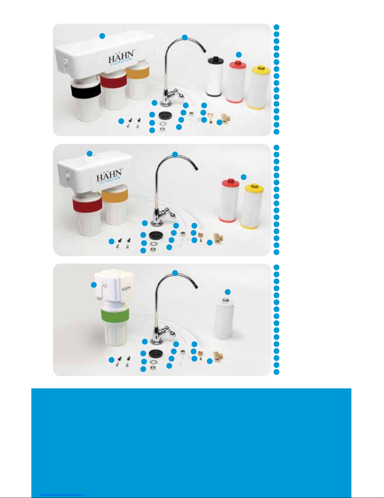
HF-3STAGE
HF-2STAGE
HF-1STAGE
A
HF-3STAGE lter unit
B
Faucet (1)
C
Filter Cartridges (3)
D
Screws with anchors (2)
E
Faucet Rubber Washer (1)
F
Faucet Spacer (1)
G
Faucet Washer (1)
H
Faucet Nut (1)
I
3’x¼” Poly tubing (1)
J
Chrome nut (1)
K
Plastic collar (2)
L
Plastic tube insert (1)
M
3’x3/8” Poly tubing (1)
N
Brass nut (1)
O
Brass tube insert (1)
P
3/8” Brass Tee (1)
A
HF-2STAGE lter unit
B
Faucet (1)
C
Filter Cartridges (2)
D
Screws with anchors (2)
E
Faucet Rubber Washer (1)
F
Faucet Spacer (1)
G
Faucet Washer (1)
H
Faucet Nut (1)
I
3’x¼” Poly tubing (1)
J
Chrome nut (1)
K
Plastic collar (2)
L
Plastic tube insert (1)
M
3’x¼” Poly tubing (1)
N
Brass nut (1)
O
Brass tube insert (1)
P
¼” Brass Tee (1)
A
HF-1STAGE lter unit
B
Faucet (1)
C
Filter Cartridge (1)
D
Screws with anchors (2)
E
Faucet Rubber Washer (1)
F
Faucet Spacer (1)
G
Faucet Washer (1)
H
Faucet Nut (1)
I
3’x¼” Poly tubing (1)
J
Chrome nut (1)
K
Plastic collar (2)
L
Plastic tube insert (1)
M
3’x¼” Poly tubing (1)
N
Brass nut (1)
O
Brass tube insert (1)
P
¼” Brass Tee (1)
D
A
B
C
E
H
L
F
I M
G
J N
K
O
P
D
D
A
A
B
B
C
C
E
E
H
H
L
L
F
F
I
I
M
M
G
G
J
J
N
N
K
K
O
O
P
P
Recommended Installation Tools
• Variable speed drill w/ 7/32" bit
• Adjustable wrench
• Measuring tape
• Bucket
• Phillips head screwdriver
• Hammer
Before beginning installation, please ensure
all parts listed are present. If any part is
missing or damaged, do not attempt to install
the lter. Please contact Customer Service for
replacement parts at (888) 245-3114.
Estimated Installation Time: 45 minutes

Installation Instructions
3
Attach white tube to the brass tee: Slide the compression nut
onto the white tubing (with threads of the nut facing the end of
the white tube). Next, slide the plastic sleeve onto the white tube.
Place brass insert into the opening of white tube. Push the tip of
the white tubing into the opening of the brass tee. While holding the
white tube in place inside the brass tee, tighten the compression
nut to compress the plastic sleeve and create a seal. NOTE: Use a
wrench to ensure complete seal. Avoid over tightening.
4
Faucet Installation: Install as shown.
Tighten nut to secure faucet to sink.
5
Faucet Connection: Connect the
outlet hose to the base of the faucet by
sliding the chrome nut onto the tube
followed by the white collar. Place the
white insert into the end of the tube.
Press the tube against the faucet base
and slide the nut and collar up to the
threads. Use wrench to ensure seal is
sufciently tight.
Note:
Avoid over-tightening.
1
Unpack and unwrap contents.
Turn off and disconnect the cold
water supply.
2
Attach threaded ends of supplied
brass tee to the cold water supply line
and shut-off valve; tighten using an
adjustable wrench.
P
E
H
F
G
L
J
K

123
0.95”
0.80”
6
Unit Installation: Select a space
under your sink for the lter
unit that is at least 12 inches
from the bottom of your cabinet
and allows for easy access to
your cold water supply and for
lter replacements. Use the
mounting holes located at the
back of the unit to mark the wall
screw placements with a pencil.
6
Center to hole differences:
HF-1STAGE: 41mm
HF-2STAGE: 65mm
HF-3STAGE: 98mm
10
Turn the cold water on. Check
for leaks and proper installation:
place a towel under the lter unit
and check for leaks. Allow water to
run for 10 minutes to ush carbon
nes. Note: Never use oils to
lubricate the O-rings; O-rings come
pre-lubricated.
9
Connect supply lines: insert tubing
from the tee tting into the inlet side
and insert tubing from the faucet into
the outlet side. Use diagram on the
right to mark tubing depth to ensure
they get inserted completely.
9
It is VERY IMPORTANT to insert tubing
completely so leaking does not occur.
7
Use a 7/32” drill bit to
drill holes for the plastic
anchors provided. Carefully
tap the anchors into the
drilled hole with a hammer.
Mount unit to the wall
with the screws. For the
HF-3STAGE — Pull the
protective plastic strip from
the battery compartment.
The red LED should ash
and beep ve (5) times to
indicate that the battery is
installed correctly.
Depth to insert 2
and 3-stage tubing
Depth to insert single stage tubing
(Diagram is actual size)
2
1
8
Attach each
sump to
the bottom
of the unit
housing. Align
connection
points, push
the sump
up and turn
to the right.
Ensure that
the sump is
locked in.

Enjoy clean, healthy water and the
peace of mind that comes from
award-winning lter technology.

Care and Maintenance
To clean your lter unit, wipe down the exterior with a damp cloth.
For the HF-3STAGE only: Once lters are at 95% capacity (about every
6 months), the battery alarm will sound and ash red when water is
owing and will continue for 15 seconds once water is turned off. Change
the battery every time you replace your lters. The battery is included
with the lter replacement cartridges.
Pure Satisfaction
All HAHN Filtration products offer a 90-day 100% satisfaction guarantee.
(A 1-year warranty is included, which covers defects in materials and
workmanship.) If for any reason you are not satised with your purchase,
simply call us or the dealer you purchased from. A Return Authorization
Code and a full refund will be promptly issued upon return. Thank you for
choosing HAHN Filtration!
This lter system is designed and tested for use with genuine HAHN
Filtration parts, including replacement lters and all hardware except for
the actual faucet. Use of parts from other manufacturers may result in loss
of contaminant reduction performance, system damage or failure. Use
of parts from other manufacturers (besides the faucet) will also void your
warranty. Please visit www.hahnltration.com for all replacement parts.

HF-123STAGE_OM_201403
HF-1STAGE
Replacement cartridge:
HF-1-R
Rated service ow:
0.5 gpm / 1.89 lpm
Max capacity:
200 gal / 757 L
Min working pressure:
20 psi (1.40 kg/cm
2
)
Max working pressure:
80 psi (5.62 kg/cm
2
)
Min operating temperature:
40° F (4.44° C)
Max operating temperature:
90° F (32.22° C)
HF-2STAGE
Replacement cartridge:
HF-2-R
Rated service ow:
0.5 gpm / 1.89 lpm
Max capacity:
450 gal / 1703.44 L
Min working pressure:
20 psi (1.40 kg/cm
2
)
Max working pressure:
80 psi (5.62 kg/cm
2
)
Min operating temperature:
40° F (4.44° C)
Max operating temperature:
90° F (32.22° C)
HF-3STAGE
Replacement cartridge:
HF-3-R
Rated service ow:
0.5 gpm / 1.89 lpm
Max capacity:
600 gal / 2271.25 L
Min working pressure:
20 psi (1.40 kg/cm
2
)
Max working pressure:
80 psi (5.62 kg/cm
2
)
Min operating temperature:
40° F (4.44° C)
Max operating temperature:
90° F (32.22° C)
The HF-2STAGE and HF-3STAGE systems are Tested and Certied
by NSF International against NSF/ANSI Standards 42, 53 and
401 for the reduction of the claims specied on the Performance
Data Sheet and substantiated by test data at www.nsf.org
Precautions:
• Filter is only to be used with cold water.
• If you experience a leak at the hose connection, disconnect and re-seat the hose.
• HAHN Filtration is not liable for consequential or incidental damages due to
improper installation.
Do not use with water that is microbiologically unsafe or of unknown water quality
without adequate disinfection before or after the system. Systems certied for cyst
reduction may be used on disinfected waters that may contain lterable cysts.
Manufactured by Sink Warehouse, LP
4601 Spicewood Springs Rd, Suite 1-100, Austin, Texas 78759
(888) 245-3114
•
www.hahnltration.com
 Loading...