


User Manual
ADSL2+ Modem/Wireless Router with VoIP Gateway
Model:LX360

User Manual
Contents
1 Introduction............................................................................................................1
1.1 Application................................................................................................1
1.2 Environment Requirements.....................................................................1
1.3 System Requirements..............................................................................1
1.4 Safety Cautions........................................................................................2
1.5 LED Status Description............................................................................2
1.5.1 Front Panel....................................................................................2
1.5.2 Rear Panel....................................................................................3
2 Hardware Installation............................................................................................4
2.1 Choosing the Best Location for Wireless Operation...............................4
2.2 Connecting the ADSL Router..................................................................5
3 Introduction to Web Configuration........................................................................6
3.1 Logging In to the Modem.........................................................................6
3.2 Summary of Device Information..............................................................7
3.3 Advanced Setup.......................................................................................7
3.3.1 Configuring PPPoE.......................................................................8
3.3.2 Bridge Configuration...................................................................13
3.4 Wireless..................................................................................................15
3.4.1 Wireless – Basic.........................................................................15
3.4.2 Wireless – Security.....................................................................16
3.4.3 Wireless – Advanced..................................................................18
3.5 Voice.......................................................................................................21
3.5.1 Registration Status......................................................................21
3.5.2 SIP Basic Setting........................................................................22
3.5.3 SIP Advanced Setting.................................................................24
3.5.4 SIP Debug Setting......................................................................26
3.5.5 VoIP Functionality.......................................................................27
3.6 USB Storage..........................................................................................31
3.7 Management..........................................................................................33
3.7.1 Settings.......................................................................................34
3.7.2 System Log.................................................................................35
i

User Manual
3.7.3 TR-069 Client..............................................................................37
3.7.4 Access Control............................................................................38
3.7.5 Update Software.........................................................................39
3.7.6 Save/Reboot...............................................................................40
4 Q&A.....................................................................................................................41
ii

User Manual
1 Introduction
The DSL Router, an ADSL2+ integrated access device (IAD), is an advanced
all-in-one gateway, incorporating VoIP, USB storage, Ethernet switch, and wireless
home networking access point, complied with the IEEE802.11b/g standards. It can
provide high access performance applications for individual users, SOHOs, small
enterprises, and so on.
Network and Router management is done through the web-based management
interface that can be accessed through the local Ethernet using any web browser.
You may also enable remote management to enable configuration of the Router via
the WAN interface.
1.1 Application
= Home gateway
= SOHOs
= Small enterprises
= Voice over IP (VoIP)
= TV over IP (IPTV)
= Higher data rate broadband sharing
= Shared broadband internet access
= Audio and video streaming and transfer
= PC file and application sharing
1.2 Environment Requirements
= Operating temperature: 0ºC~40ºC (32ºF to 104ºF)
= Storage temperature: -10ºC~55ºC (14ºF to 131ºF)
= Operating humidity: 10%~95%, non-condensing
= Storage humidity: 5%~95%, non-condensing
= Power adapter input: 100V~240V AC, 50/60Hz
= Power adapter output: 12V DC, 2A
1.3 System Requirements
1

User Manual
Recommended system requirements are as follows:
= Pentium 233 MHZ or above
= Memory: 64 Mbps or above
= 10M Base-T Ethernet or above
= Windows 9x, Windows 2000, Windows XP, Windows ME, Windows NT
= Ethernet network interface card
1.4 Safety Cautions
Follow the announcements below to protect the device from risks and damage
caused by fire and electric power.
= Use volume labels to mark the type of power.
= Use the power adapter that is packed within the device package.
= Pay attention to the power load of the outlet or prolonged lines. An
overburden power outlet or damaged lines and plugs may cause electric
shock or fire accident. Check the power cords regularly. If you find any
damage, replace it at once.
= Proper space left for heat radiation is necessary to avoid any damage
caused by overheating to the device. The holes are designed for heat
radiation to ensure that the device works normally. Do not cover these heat
radiant holes.
= Do not put this device close to a place where a heat source exits or high
temperature occurs. Avoid the device from direct sunshine.
= Do not put this device close to a place where is over damp or watery. Do not
spill any fluid on this device.
= Do not connect this device to any PC or electronic product, unless our
customer engineer or your broadband provider instructs you to do this,
because any wrong connection may cause any power or fire risk.
= Do not place this device on an unstable surface or support.
1.5 LED Status Description
1.5.1 Front Panel
2
User Manual
Indicator Status Description
Power
ADSL
Internet
Ethernet4/3/2/1
USB1/2
WLAN
VoIP1/2
Off Power not supplied.
On Power supplied.
Quick blink DSL line is training.
On DSL line is connected.
Off DSL line is disconnected.
Off No connection.
Blink DSL traffic is flowing.
On The users can access the Internet.
Off No Ethernet signal is detected.
Blink
On Ethernet interface is ready to work
Off No USB device is detected.
Blink The user data is passing through USB
On The USB interface is ready to work.
Off No radio signal is detected.
Blink
On WLAN interface is ready to work.
Off VoIP phone is not registered.
Blink Phone is off-hook.
On VoIP phone is registered.
The user data is passing through
Ethernet port.
port.
The user data is passing through
WLAN port.
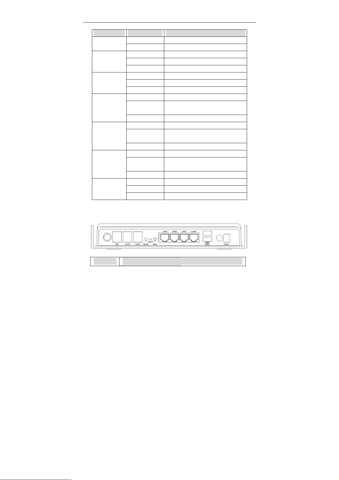
1.5.2 Rear Panel
Interface Description
3

User Manual
DSL
VoIP1/2 Connect to phone for VoIP application.
WLAN
Reset
WPS
LAN1/2/3/4
USB1/2
Power
Wireless antenna.
RJ-11 port, using the telephone line to connect the modem
with the ADSL cable or splitter.
Enable or disable the WLAN. Press the button for to enable
the WLAN.
To restore the factory default, keep the device powered on
and push a long needle into the hole. Press down the
button and then release.
Enable or disable the WPS. Press the button to enable the
WPS.
RJ-45 port, connect the modem to a PC or other network
device.
USB host port, connect to another USB device to supply
some value-added application.
Power switch.
Power supplied port, plug in for power adapter that the
power input is 12V DC, 2 A.
2 Hardware Installation
2.1 Choosing the Best Location for Wireless Operation
= Keep the numbers of walls and ceilings to the minimum:
The signal emitted from wireless LAN devices can penetrate through ceilings
and walls. However, each wall or ceiling can reduce the range of wireless
LAN devices from 1 ~ 30 miters. Position your wireless devices so that the
number of walls or ceilings obstructing the signal path is minimized.
= Consider the direct line between access points and workstations:
A wall that is 0.5 meters thick, at a 45-degree angle appears to be almost 1
meter thick. At a 2-degree angle, it appears over 14 meters thick. Be careful
to position access points and client adapters so the signal can travel straight
through (90º angle) a wall or ceiling for better reception.
4

User Manual
= Building materials make difference:
Buildings constructed using metal framing or doors can reduce effective
range of the device. If possible, position wireless devices so that their
signals can pass through drywall or open doorways. Avoid positioning them
in the way that their signal must pass through metallic materials. Poured
concrete walls are reinforced with steel while cinderblock walls generally
have little or no structural steel.
= Position the antenna for best reception:
Play around with the antenna position to see if signal strength improves.
Some adapters or access points allow you to judge the strength of the
signal.
= Keep your product away (at least 1~2 meters) from electrical devices:
= Keep wireless devices away from electrical devices that generate RF noise
such as microwave ovens, monitors, electric motors, etc.
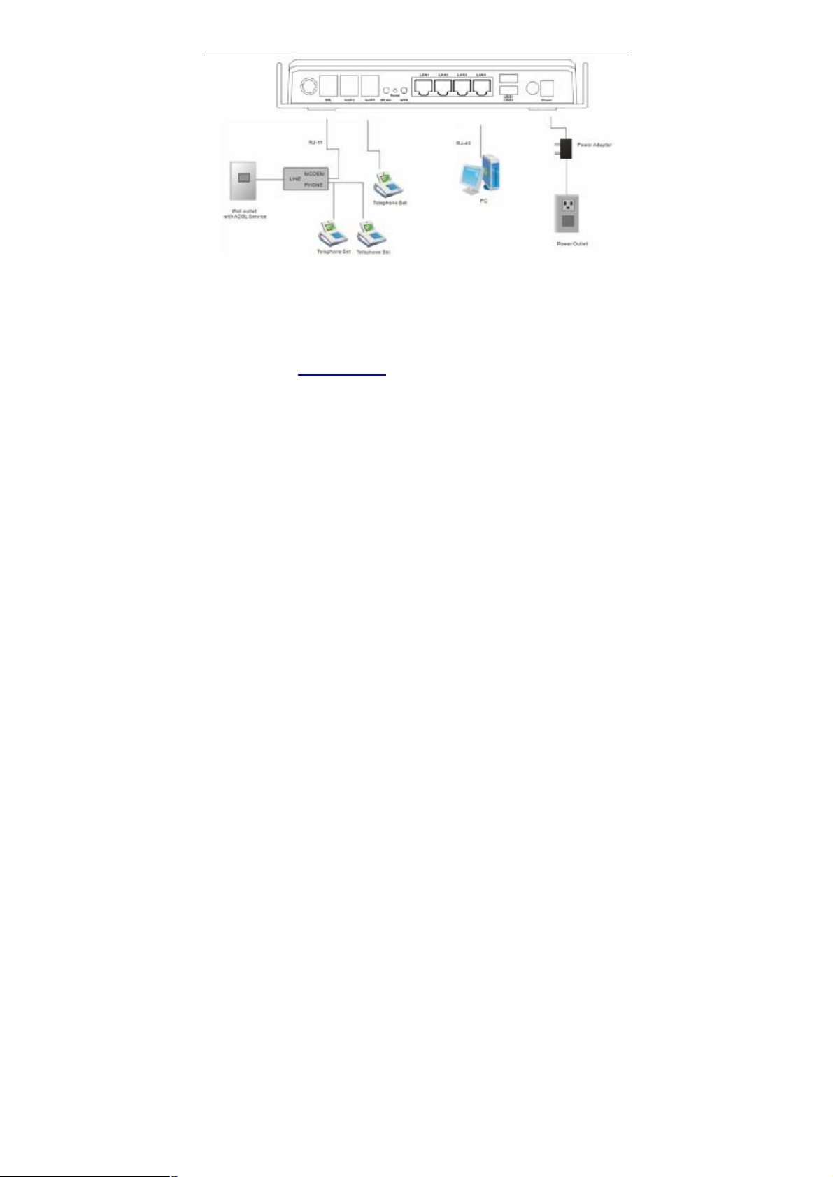
2.2 Connecting the ADSL Router
= See the following figure. Connect the DSL port of the DSL Router with a
telephone cable.
= Connect the LAN port of the DSL Router to the network card of the PC via an
Ethernet cable.
= Connect the VoIP port of the DSL Router to the phone.
= Plug one end of the power adapter to the wall outlet and connect the other
end to the PWR port of the DSL Router.
The following figure displays the connection of the DSL Router, PC, and
telephones.
5
User Manual
3 Introduction to Web Configuration
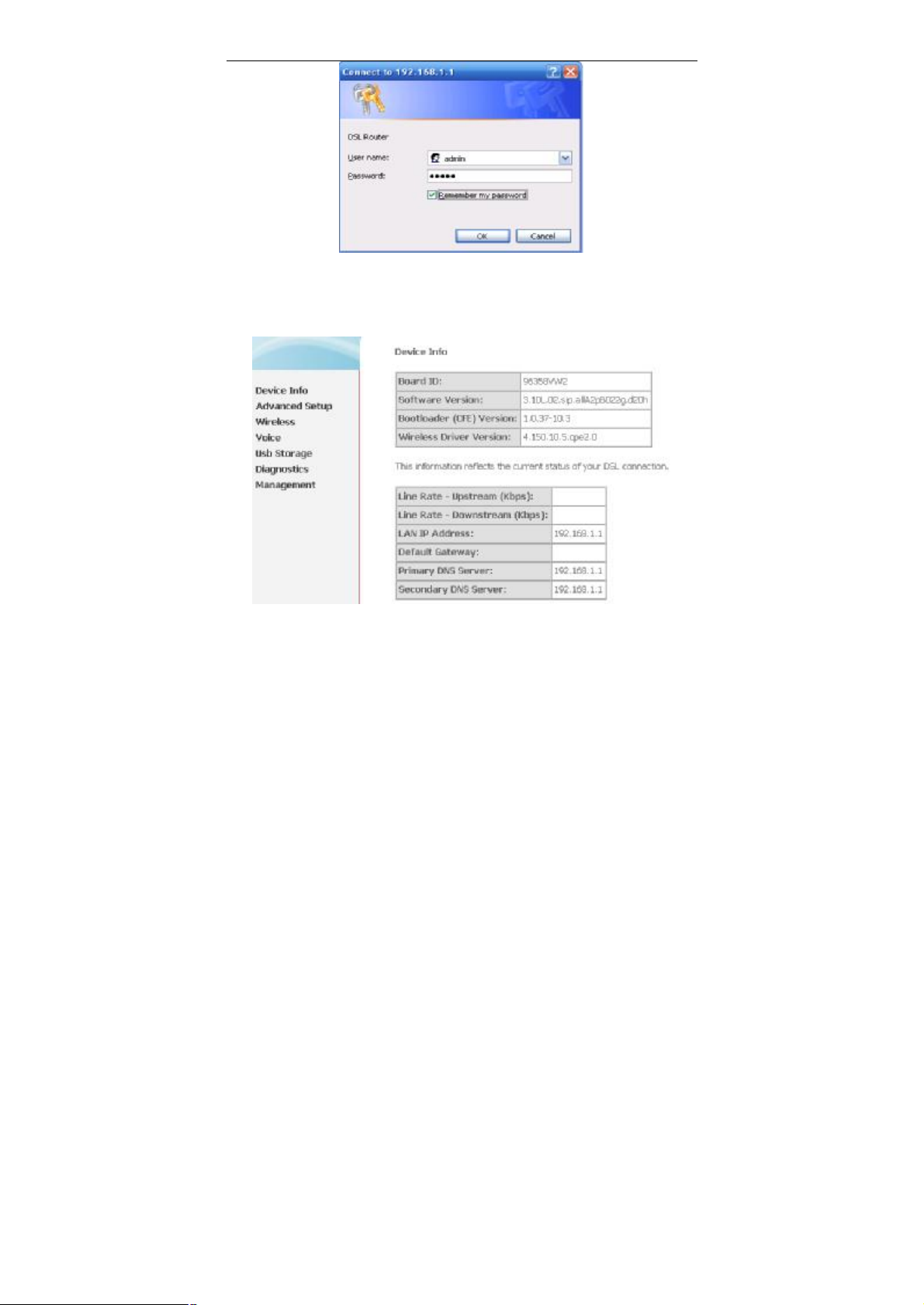
3.1 Logging In to the Modem
Step 1 Open a Web browser on your computer.
Step 2 Enter http://192.168.1.1 (DSL router default IP address) in the address
bar. The login page appears.
Step 3 Enter a user name and the password. The default username and
password of the super user are admin and admin. The username and
password of the common user are user and user. You need not enter
the username and password again if you select the option Remember
my password. It is recommended to change these default values after
logging in to the DSL router for the first time.
Step 4 Click OK to log in or click Cancel to exit the login page.
6
User Manual
3.2 Summary of Device Information
After logging in to the DSL router, the home page appears. In this page, you can view the
summary of device
= Default Gateway: In the bridging mode there is no gateway. In other modes,
it is the address of the uplink equipment, for example, PPPoE/PPPoA.
= DNS Server: In the PPPoE / PPPoA mode, it is obtained from the uplink
equipment. In the bridging mode, there is no DNS Server address and you
can manually enter the information.
3.3 Advanced Setup
7
User Manual
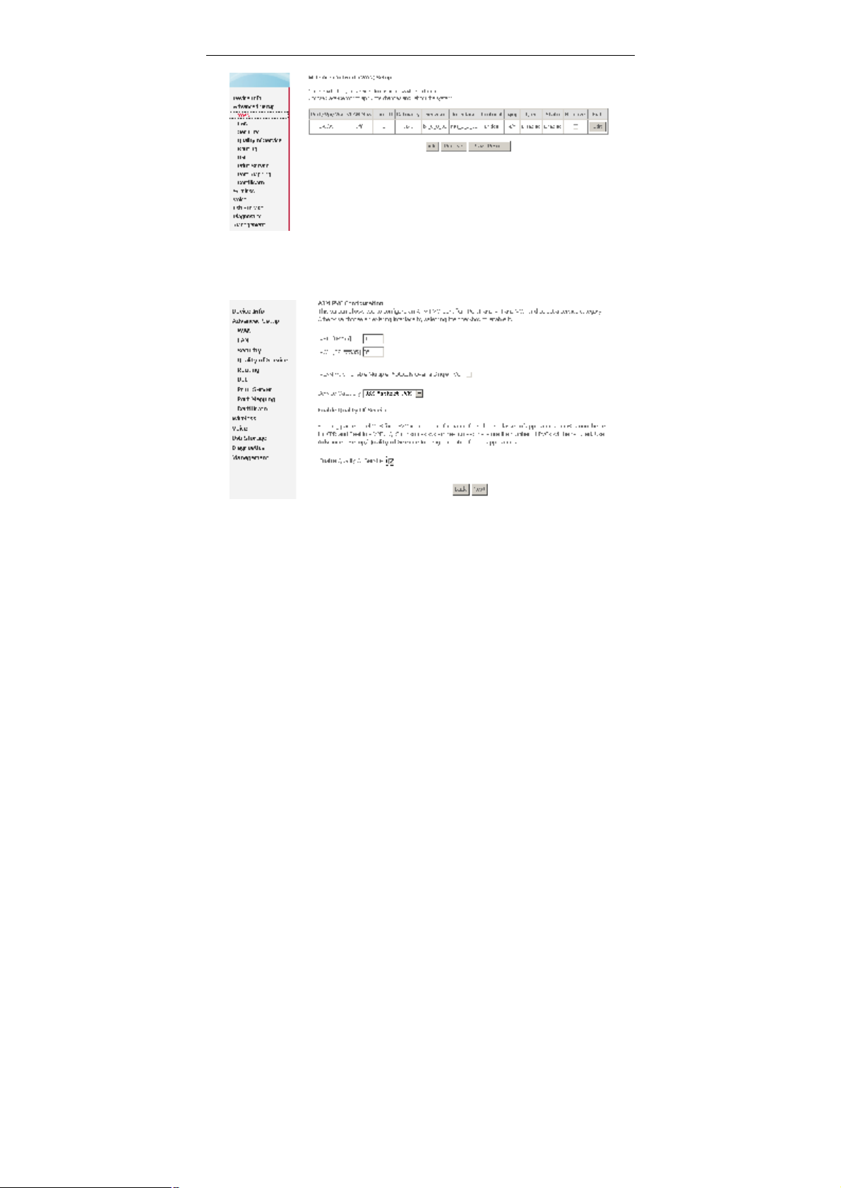
Choose Advanced Setup > WAN, and the following page appears.
3.3.1 Configuring PPPoE
Step 1 Click Add and the following page appears. In this page, you can modify
VPI/VCI, service categories, and QoS.
= VPI: Virtual path between two points in an ATM network. Its valid value range
is from 0 to 255.
= VCI: Virtual channel between two points in an ATM network. Its valid value
range is from 32 to 65535 (1 to 31 are reserved for known protocols).
= Service Category: UBR Without PCR/UBR With PCR/CBR/Non Realtime
VBR/Realtime VBR.
= Enable Quality Of Service: Enable or disable QoS.
After proper modifications, click Next and the following page appears.
Step 2 In this page, you can modify the Internet connection type and
encapsulation type.
8

User Manual
Change the connection type of PVC 0/35 to PPP over Ethernet (PPPoE) and set
the Encapsulation Mode to LLC/SNAP-BRIDGING (according to the uplink
equipment). Click Next and the following page appears.
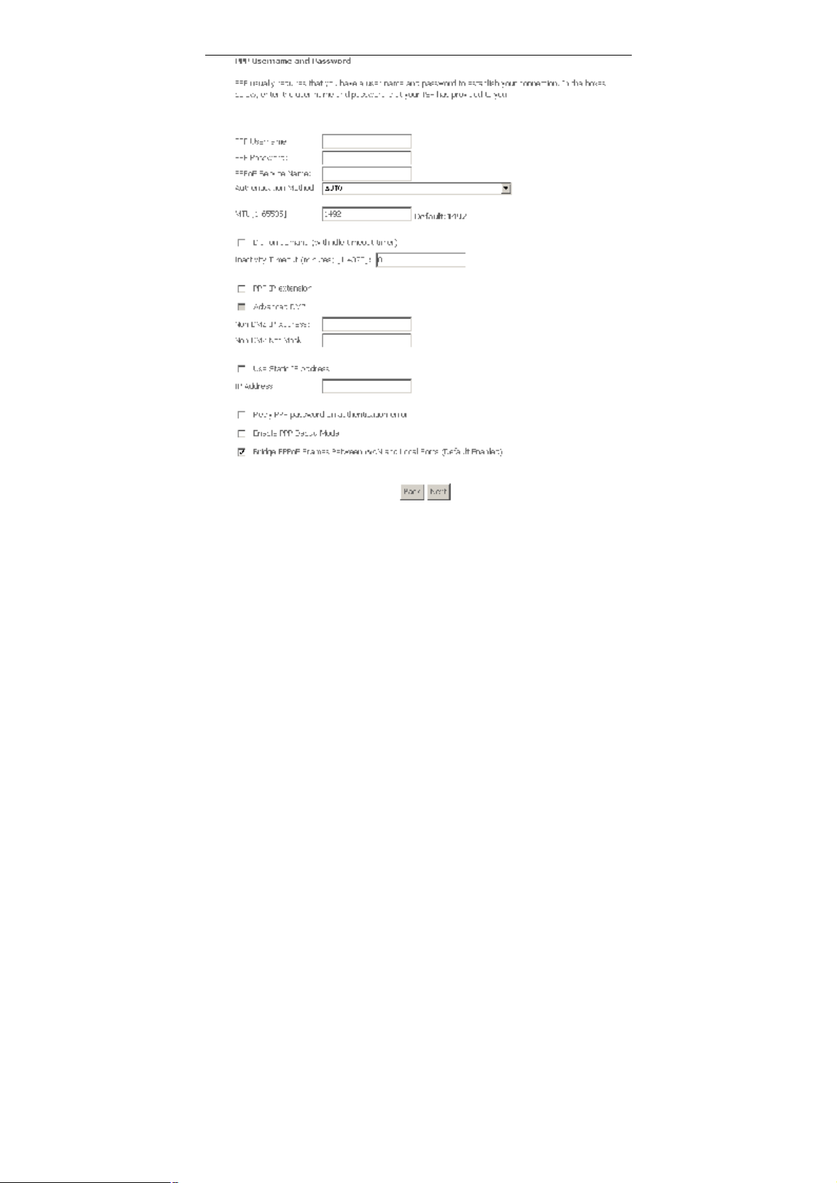
Step 3 In this page, you can modify the PPP user name, PPP password,
authentication method.
9
User Manual
= PPP Username: The correct user name that your ISP provides to you.
= PPP Password: The correct password that your ISP provides to you.
= PPPoE Service Name: If your ISP provides it to you, please enter it. If not,
do not enter any information.
= Authentication Method: The value can be AUTO, PAP, CHAP, or MSCHAP.
Usually, you can select AUTO.
= Dial on demand (with idle timeout timer): If this function is enabled, you
need to enter the idle timeout time. Within the preset minutes, if the modem
does not detect the flow of the user continuously, the modem automatically
10

User Manual
stops the PPPoE connection. Once it detects the flow (like access to a
webpage), the modem restarts the PPPoE dialup.
If this function is disabled, the modem performs PPPoE dial-up all the time. The
PPPoE connnection does not stop, unless the modem is powered off and DSLAM
or uplink equipment is abnormal.
= PPP IP extension: If this function is enabled, the WAN IP address obtained
by the modem through built-in dial-up can be directly assigned to the PC
being attached to the modem (at this time, the modem connects to only one
PC). From the aspect of the PC user, the PC dials up to obtain an IP addres.
But actually, the dial-up is done by the modem.
If this function is disabled, the modem itself obtains the WAN IP address.
= Advanced DMZ: This is the virtual server configuration option. The DMZ
host feature allows one local computer to be exposed to the Internet. In this
way, other computers can easily access the DMZ host, the DMZ host is not
protected by the firewall, and may be vulnerable to attack. This may also put
other computers in the home network at risk. When designating a DMZ host,
you must consider the security implications and protect it if necessary. To set
up a DMZ host, you should enable the PPP IP extension first.
= Non DMZ IP Address: The DMZ host IP address. You can modify it.
= Non DMZ Net Mask: The DMZ host subnet mask. It is build upon the DMZ
host IP address.
= Use Static IP Address: If this function is disabled, the modem obtains an IP
address assigned by an uplink equipment such as BAS, through PPPoE
dial-up.If this function is enabled, the modem uses this IP address as the
WAN IP address.
After entering the PPP user name and password, click Next and the following page
appears.
In this page, you can modify the service name, and enable or disable the IGMP
multicast and WAN service.
11

User Manual
= Enable IGMP Multicast: IGMP proxy. For example, if you wish that the
PPPoE mode supports IPTV, enable this function.
= Enable WAN Service: Enable it, unless you do not want to active the PVC.
Click Next, and the following page appears. This page shows all the configuration.
You can view the default values of NAT enable and Firewall enable.
To save the settings, click Save. To make any modifications, click Back. After you
click Save, the following page appears.
Note: You need to reboot the modem to activate this WAN interface and further
configure services in this interface.
12

User Manual
3.3.2 Bridge Configuration
This section describes the procedure for adding PVC 0/35 (Bridge mode).
Click Add, and the following page appears. In this page, you can modify VPI/VCIs,
service categories, and QoS.
In this example, PVC 0/35 is to be modified and the default values of service
category remain. In actual applications, you can modify them as required.
After proper modifications, click Next and the following page appears. In this page,
you can modify the Internet connection type and encapsulation type.
13

User Manual
Click Next and the following page appears. In this page, you can modify the service
name.
= Enable Bridge Service: Enable it, unless you do not want to active the PVC.
Click Next and the following page appears. This page shows all the configuration.
14

User Manual
To save the settings, click Save. To make any modifications, click Back. After you
click Save, the following page appears.
Note: You need to reboot the modem to activate this WAN interface and further
configure services in this interface.
3.4 Wireless
3.4.1 Wireless – Basic
Choose Wireless > Basic, and the following page appears.
15

User Manual
= Enable Wireless: If you want to make wireless be available, you have to
check this box first. Otherwise, the Hide Access Point SSID, Country, Enable
Wireless Guest Network, and Guest SSID box will not be displayed.
= Hide Access Point: Check this box if you want to hide any access point for
your router, so a station cannot obtain the SSID through passive scanning.
= SSID: The SSID (Service Set Identification) is the unique name shared
among all devices in a wireless network. The SSID must be identical for all
devices in the wireless network.
= Country: The channel will adjust according to nations to adapt to frequency
provision of each nation.
= Guest SSID: The SSID (Service Set Identification) is the unique name
shared among all devices in a guest wireless network. The SSID must be
identical for all devices in the guest wireless network.
3.4.2 Wireless – Security
Choose Wireless > Security, and the following page appears.
16

User Manual
In this page, the data is not encrypted when it is transferred from the device to the
client station. This is the default option.
= Select SSID: Select the wireless LAN of SSID to configure security features.
= Network Authentication: Select the authentication mode for the selected
wireless LAN of SSID to be open. That is no WEP encryption, so the WEP
Encryption is disabled.
64-bit WEP
If you select the “Shared” as the Network Authentication, you can select 64-bit or
128-bit as the Encryption Strength. In the following figure, select 64-bit as an
example.
17

User Manual
= Network Authentication: Select the authentication mode for the selected
wireless LAN of SSID to be open or shared.
= WEP Encryption: Enable WEP Encryption.
= Encryption Strength: Select the desired Data Security level to be 64-bit.
= Current Network Key: Select one of network key that you set on the Key
boxes as default one.
= Network Key 1 to 4: Enter 5 ASCII characters or 10 hexadecimal digits for
64-bit encryption keys to fill out WEP keys box. The system allows you to
type in 4 kinds of the WEP key.
The authentication modes are as follows: 802.1X, WPA, WPA-PSK,WPA2, WPA2
–PSK, Mixed WPA2/WPA, Mixed WPA2/WPA – PSK.
After proper configuration, click Save/Apply to save the wireless security options
and make the modification effect.
3.4.3 Wireless – Advanced
Choose Wireless > Advanced, and the following page appears. This page allows
you to configure advanced features of the wireless LAN interface. You can select a
particular channel on which to operate, force the transmission rate to a particular
speed, set the fragmentation threshold, set the RTS threshold, set the wakeup
interval for clients in power-save mode, set the beacon interval for the access point,
set XPress mode and set whether short or long preambles are used.
18

User Manual
= Band: Select 802.11b/g using wireless frequency band range. The radio
frequency remains at 2.437 GHz.
= Channel: Fill in the appropriate channel to correspond with your network
settings. The default value is Auto. All devices in your wireless network must
use the same channel in order to work correctly. This router supports auto
channeling functionality.
= Auto Channel Timer(min): Specifies the timer of auto channelling.
= 54g™ Rate: Select the transmission rate for the network. The rate of data
transmission should be set depending on the speed of your wireless network.
You can select from a range of transmission speeds, or you can select Auto
to have the Router automatically use the fastest possible data rate and
enable the Auto-Fallback feature. Auto-Fallback will negotiate the best
possible connection speed between the Router and a wireless client. The
default value is Auto.
= Multicast Rate: Select the multicast transmission rate for the network. The
rate of data transmission should be set depending on the speed of your
wireless network. You can select from a range of transmission speeds, or
you can select Auto to have the Router automatically use the fastest
possible data rate and enable the Auto-Fallback feature. Auto-Fallback will
negotiate the best possible connection speed between the Router and a
wireless client. The default value is Auto.
= Basic Rate: Select the basic transmission rate ability for the AP.
= Fragmentation Threshold: Packets that are larger than this threshold are
fragmented into multiple packets. Try to increase the fragmentation threshold
19

User Manual
if you encounter high packet error rates. Do not set the threshold too low,
since this can result in reduced networking performance.
= RTS Threshold: This value should remain at its default setting of
2347.Should you encounter inconsistent data flow, only minor reductions are
recommended. Should you encounter inconsistent data flow, only minor
reduction of the default value, 2347, is recommended. If a network packet is
smaller than the preset RTS threshold size, the RTS/CTS mechanism will not
be enabled. The Router sends Request to Send (RTS) frames to a particular
receiving station and negotiates the sending of a data frame. After receiving
an RTS, the wireless station responds with a Clear to Send (CTS) frame to
acknowledge the right to begin transmission. The RTS Threshold value
should remain at its default value of 2347.
= DTIM Interval: Enter a value between 1 and 255 for the Delivery Traffic
Indication Message (DTIM.) A DTIM is a countdown informing clients of the
next window for listening to broadcast and multicast messages.
= Beacon Interval: A beacon is a packet of information that is sent from a
connected device to all other devices where it announces its availability and
readiness. A beacon interval is a period of time (sent with the beacon) before
sending the beacon again. The beacon interval may be adjusted in
milliseconds (ms). Default (100) is recommended.
= XPress™ Technology: Select Enabled or Disabled. This is a special
accelerating technology for IEEE802.11g. The defaule is Disabled.
= 54g™ Mode: Compatible with IEEE 802.11b, IEEE 802.11g. Select a
Standards from the drop-down list box. Its default setting is 54g Auto. The
drop-down list box includes below mode:
– 802.11b Only: Only stations that are configured in 802.11b mode can
associate. If you select it, the rate of transmission only has selected
values: 1 Mbps, 2 Mbps, 5.5 Mbps, and 11 Mbps. For other selections,
the rate of transmission has lots of selected values: 1 Mbps, 2 Mbps,
5.5 Mbps, 6 Mbps, 9 Mbps, 11 Mbps, 12 Mbps, 18 Mbps, 24 Mbps, 36
Mbps, 48 Mbps, 54 Mbps.
– 54g LRS: This is a special compatibility mode for 802.11b/g and is in
fact designed for older types of b-clients. Use this mode if you are
experiencing problems with wireless clients that connect to the
Gawv5.4U4-A3 Access Point. If you select it, the preamble type will be
disabled, which cannot be set.
– 54g Auto: Only stations that are configured in 802.11b/g mode can
associate.
– 54g Perfomance: Only stations that are configured in 802.11g mode
can associate. It is the same as 54g LRS, if you select it, the preamble
type will be disabled, which cannot be set.
20

User Manual
= 54g™ Protection: The 802.11g standards provide a protection method so
802.11g and 802.11b devices can co-exist in the same network without
“speaking” at the same time. Do not disable 54g Protection if there is a
possibility that a 802.11b device may need to use your wireless network. In
Auto Mode, the wireless device will use RTS/CTS to improve 802.11g
performance in mixed 802.11g/802.11b networks. Turn protection off to
maximize 802.11g throughput under most conditions.
= Preamble Type: Preambles are a sequence of binary bits that help the
receivers synchronize and ready for receipt of a data transmission. Some
older wireless systems like 802.11b implementation use shorter preambles. If
you are having difficulty connecting to an older 802.11b device, try using a
short preamble. You can select short preamble only if the 54g mode is set to
802.11b.
= Transmit Power: Adjust the transmission range here. This tool can be
helpful for security purposes if you wish to limit the transmission range.
= WMM(Wi-Fi Multimedia): Select whether WMM is enable or disabled.
Before you disable WMM, you should understand that all QoS queues or
traffic classes relate to wireless do not take effects.
= WMM No Acknowledgement: Select whether ACK in WMM packet. By
default, the Ack Policy for each access category is set to Disable, meaning
that an acknowledge packet is returned for every packet received. This
provides a more reliable transmission but increases traffic load, which
decreases performance. To disable the acknowledgement can be useful for
voice, for example, where speed of transmission is important and packet loss
is tolerable to a certain degree.
= WMM APSD: APSD is short for automatic power save delivery, Selecting
enable makes it have very low power consumption. WMM Power Save is an
improvement to the 802.11e amendment adding advanced power
management functionality to WMM.
Click Save/Apply to configure the advanced wireless options and make the
changes take effect.
3.5 Voice
The VoIP page does not contains Save/Apply button, but you can save your
configurations by clicking Stop SIP client or Start SIP client. Both of the actions
can save the configurations. If you want to start the VoIP service, click Start SIP
client. If you want to stop the VoIP service, click Stop SIP client.
3.5.1 Registration Status
Choose Voice > Registration Status, the following page appears. In this page,
you can view the status of Voice line registration.
21

User Manual
3.5.2 SIP Basic Setting
Choose Voice > SIP Basic Setting, the following page appears. In this page, you
can configure the SIP basic parameters.
= Interface name: This item provides for you to choose the way which VoIP of
the DSL router connects to SIP Proxy.
22

User Manual
= Locale selection: This item provides for you to choose country where your
locale in. The different country use different standards used by DSL router
VoIP module, such as ring tone standard. Locale selection default value is
USA.
= Preferred code list: This item provides for you to specify the priority of
codec, and the priority of codec declined from up to down. Codecs define the
method of relaying voice data. Different codecs have different characteristics,
such as data compression and voice quality. For Example, G.723 is a codec
that uses compression, so it is good for use where bandwidth is limited but its
voice quality is not as good compared to other codecs such as the G.711.If
you specify none of the codecs, using the default value, the DSL ROUTER
choose the codec automatically.
= SIP domain name: The IAD SIP domain name of UA. If the SIP UA has no
domain name, let it be blank and the IAD can use the IP address of VoIP
WAN interface.
= Use SIP Proxy: Select the check box if your DSL router uses a SIP proxy.
SIP proxy allows other parties to call DSL router through it.
= Use SIP Outbound Proxy: Some network service providers require the use
of an outbound proxy. This is an additional proxy, through which all outgoing
calls are directed. In some cases, the outbound proxy is placed alongside the
firewall and is the only way to let SIP traffic pass from the internal network to
the Internet.
= Use SIP Registrar: Select this option to register with the proxy. You can
register your USER ID on the SIP Registrar. SIP Registrar works with SIP
Proxy, allowing other parties to call DSL ROUTER through it.
= LineDisabled: Line number is a telephone port in the Router to which you
can connect a standard (POTS) telephone. If you check this option, and the
line corresponding you checked is disable. You can not use it to initiate or
accept any call.
= Extension: This is VoIP user ID of telephone, used for identification to
initiate and accept calls.
= Display Name: A free text description which is displayed to remote parties
as your caller ID.
= Authentication Name: The login name used for authentication with the SIP
proxy.
= Password: The password used for authentication with the SIP proxy.
23

User Manual
Note: Click Start SIP client or Stop SIP client to save the configurations.
3.5.3 SIP Advanced Setting
Choose Voice > SIP Advanced Setting, the following page appears. In this page,
you can configure the SIP advanced parameters.
= Forwarding number: Set the number to forward a call. This number can
also be set through dialing ‘*74<NUM>#’ on the phone key pad.
= Call forwarding when busy: Enable Call forwarding when busy. When
this box is checked, incoming calls are forwarded to an appointed number
(see Forwarding number) when the specific line is busy. It has the same
effect as dialing *72 on the phone pad.
= Forwarding all calls: Enable Forwarding all calls. When this box is
checked, incoming calls are forwarded to an appointed number (see
Forwarding number) unconditionally. Dialing *73 can also accomplish this
service.
= Call forwarding if no answer: Enable Call forwarding if no answer. When
this box is checked, incoming calls are forwarded to an appointed number
when it is not answered in 18s. Dialing *71 can also accomplish this service.
24

User Manual
= Call waiting: If call waiting is enabled on a line (see feature codes on the
below), and you hear the call waiting tone during a call, press flash to answer
the second call. The first call is automatically placed on hold. To switch
between calls, press flash again.
– Check the feature “Call waiting” to enable this function
– Dial ‘*61’ can also enable Call waiting and dial ‘*60’ can also disable
Call waiting
– Call forward feature settings (Busy or All) takes priority over the call
waiting feature
– Call waiting feature is ignored on new incoming calls if there is already a
call on hold or in conference
= Enable MWI subscription: MWI stands for message waiting indicator. When
set this enabled, the Router sends a SIP SUBSCRIBE message to proxy,
asking for a notification when its voicemail status changes. When its status
do changes, the proxy sends a NOTIFY message to gateway, causing a MWI
tone streamed to the handset of the user.
= Enable T38 support: Checking this box enables T38 support. When doing a
fax transmission on the Router, after fax tone been detected, fax
transmission switches to T38 mode.
= Registration Expire Timeout: It is the interval the Router initiates a new
registration since last one. It is also known as ‘registration assurance timer’.
The gateway uses this mechanism to keep its binding record updated.
= Dialpan Setting: Set the VoIP dial plan. If user-dialed number matches it, the
number is processed by the Router immediately.
= Dtmf Relay setting: Set DTMF transmit method, which can be following
values:
– SIP Info: Use SIP INFO message to transmit DTMF digits.
– RFC2833: Use RTP packet to encapsulate DTMF events, as specified
in RFC 2833.
– Voice Band: DTMF events are mixed with user voice in RTP packet.
= SIP Transport protocol: Select the transport protocol to use for SIP
signaling. Note that SIP proxy and registrar need to support the protocol you
choose.
= Incoming PSTN Call Routing: Select the way incoming PSTN calls to be
routed. It has following items:
25

User Manual
– Auto - PSTN Call switch to idle line: The Router automatically selects
the idle line for incoming PSTN call.
– Line1 - PSTN Call switch to Line1: PSTN call is routed to line 1. If it is
busy, PSTN call fails.
– Line2 - PSTN Call switch to Line2: PSTN call is routed to line 2.
– VoIP - PSTN Call switch to VoIP call: PSTN call can be routed to VoIP
extension, which is filled in ‘PSTN Call Routing Data’.
= PSTN Dialpan Setting: Set the PSTN dial plan. If user-dialed number
matches it fully, the number can be processed by DSL router immediately
and make PSTN call.
= Enable SIP tag matching (Uncheck for Vonage Interop): Enable the
checking of the ‘to’ tag in SIP message. Enabling this feature may impose
more strictly checking on SIP messages. If you place the Router in a Vonage
network, using the Vonage server, make sure to uncheck it.
= Enable Music Server: When set enabled, the holding party acts like a
coordinator, and triggers the music server to stream music to the hold party.
This is done by sending an INVITE without SDP to music server, and
acknowledging response of the server with an ACK message containing the
SDP of the hold party. Music server then streams music to hold party.
Note: Click Start SIP client or Stop SIP client to save the configurations.
3.5.4 SIP Debug Setting
Choose Voice > SIP Debug Setting, the following page appears.
26

User Manual
= Remote server for SIP log message: For SIP Debugging. Set one IP
address and one port. The SIP message (both send and receive) of IAD
send to the setting host.
= Enable Vad support: Configure voice activity detection (VAD) and comfort
noise generator (CNG).
= Ingress Gain: Set receiving gain.
= Egress Gain: Set transmitting gain.
= Enable Echo Restrain: Set echo canceller.
= Jitter Buffer: Set gain of jitter buffer. You can set a static buffer or select
Auto. Auto means adaptive buffer.
Note: Click Start SIP client or Stop SIP client to save the configurations.
3.5.5 VoIP Functionality
This section describes how to use the functionality of the Router. Some features
involve 2 or 3 parties. In that case, note that all 3 parties have to be successfully
registered.
3.5.5.1 Registering
Before using any VoIP functionality, the Router must register itself to a registrar. the
Router also has to be configured with a proxy, which relays VoIP signaling to next
27

User Manual
hop. In fact, many implementations integrate these two into one server, so in many
case registrar and proxy refer to the same IP.
(1) Select the right interface to use for registering, depending on where
Proxy/Registrar resides. If use WAN link, make sure it is already up.
(2) Fill SIP domain name with the IP address or the domain name of the SIP proxy.
Note if we use domain name, it must be resolvable to the IP address of the
proxy.
(3) Select the Use SIP Registrar check box and enter the right value in the IP/Port
field.
(4) Fill the extension information: Extension, Display Name, Authentication
Name and Password. Authentication Name and Password must be
pre-configured in registrar database.
(5) Click Stop SIP client (if VoIP application has been started already), then Start
SIP client to make above settings take effect.
(6) VoIP LED should be on, indicating that SIP client is successfully registered.
3.5.5.2 Placing a call
This section depicts how to place a basic VoIP call.
(1) Pick up the handset on the phone.
(2) Now you hear the dial-tone. Dial the extension of remote party
(3) To end the dialing, wait for digit-timeout, or just press # immediately.
(4) After remote party answers the call, you are in voice connection.
3.5.5.3 Anonymous call
Anonymous call does not send the caller ID to remote party. This is useful if you
don’t want others know whom you are.
(1) Pick up the handset on the phone.
(2) Dial *83 to enable anonymous call.
(3) Hook on the handset, and dial another extension as you like. Now your caller ID
information is blocked.
(4) To enable caller ID transmission again, dial *84 on the key pad.
3.5.5.4 Do Not Disturb (DND)
If DND enabled, all incoming calls will be rejected. DND is useful if you do not want
others to bother you.
28

User Manual
(1) Pick up the handset on the phone.
(2) Dial *86 to enable DND function
(3) Hook on the phone. Now your phone rejects all incoming calls.
(4) To disable DND, press *87 on the key pad.
3.5.5.5 Redial
For outgoing calls, DSL Router remembers the number you dial. Next time when
you want to dial that person, the Router provides you the redial functionality.
(1) To re-dial the latest dialed person, press *68 on the key pad.
(2) Now you have made the call, as if you just dialed the whole number.
3.5.5.6 Call Return
For incoming calls, the Router remembers the number of calling party.
(1) To return a call, press *69.
(2) Now you have made the call as if you have dialed the whole number
3.5.5.7 Call Hold
Call hold enable you put a call to a pending state, and pick it in future.
(1) Assuming you are in a voice connection, you can press FLASH to hold current
call.
(2) Now you can call another party, or press FLASH again to return to first call.
3.5.5.8 Call Waiting
Enabling call waiting allows third party to call in when you are in a voice
connection.
(1) Pick up the phone attached to the Router.
(2) Press *61 to enable call waiting function.
(3) Assuming that you are in a voice connection, when another call comes in, the
Router streams a call waiting tone to your phone, indicating another call is
available.
(4) Press FLASH switches to this call and the initial call puts to hold automatically.
(5) Press FLASH for several times switches between these two calls back and
forth.
(6) Pressing *60 disables call waiting function.
29

User Manual
3.5.5.9 Blind Transfer
Bind transfer transfers the current call to a third party blindly, regardless of whether
the transfer is successfully.
(1) Assume that you have already been in a voice connection.
(2) Press FLASH to hold the first party.
(3) Dial a third party.
(4) Before the third party answers the call, hook on your phone.
(5) Now the first party takes over the call and is in connection with the third party.
3.5.5.10 Consultative Transfer
Consultative transfer lets the third party answer the transferred call, and then hook
on the transferring party. It is gentler than blind transfer.
(1) Assume you have already been in a voice connection with a first party.
(2) Press FLASH to hold the first party.
(3) Dial a third party.
(4) After the third party answers the call, hook on your phone.
(5) Now the first party takes over the call and is in connection with the third party.
3.5.5.11 Call Forwarding No Answer
If this feature enabled, incoming calls are forwarded to third party when you doesn’t
answer them. It involves two steps: setting the forwarding number and enable the
feature.
(1) Dial *74<NUM># to set forwarding number, where NUM is the number of the
party whom the call is forwarded to.
(2) Dial *71 to enable call forwarding no answer. That is, when our phone doesn’t
answer incoming call, this call will be forwarded.
(3) Press *70 disables call forwarding no answer.
3.5.5.12 Call Forwarding Busy
If this feature enabled, incoming calls are forwarded to third party when you busy. It
involves two steps: setting the forwarding number and enable the feature.
(1) Dial *74<NUM># to set forwarding number, where NUM is the number of the
party whom the call is forwarded to. Note that if we have already set
forwarding number before, this step can be omitted.
30

User Manual
(2) Press *72 to enable call forwarding busy. That is, when our phone gets busy,
this call will be forwarded.
(3) Press *70 disables call forwarding busy.
3.5.5.13 Call Forwarding All
If this feature enabled, incoming calls will be forwarded to third party without any
reason. It involves two steps: setting the forwarding number and enable the
feature.
(1) Dial *74<NUM># to set forwarding number, where NUM is the number of the
party whom the call is forwarded to. Note if we have already set
forwarding number before, this step can be omitted.
(2) Press *73 to enable call forwarding all. That is, all incoming alls will be
forwarded to the third party.
(3) Press *75 disables call forwarding all, but lets call forwarding no answer and
call forwarding busy unchanged.
(4) Press *70 disables all call forwarding function.
3.5.5.14 3-Way Conference
3-way conference enables you to invite a third party to a call, and every person in
the conference is able to hear others’ voice.
(1) Assume you are in connection with a first party.
(2) Press FALSH to put the first party on hold.
(3) Dial a third party.
(4) After the third party answers the call, press FALSH again to invite the first party.
(5) Now all three parties are in a 3-way conference.
3.6 USB Storage
Choose USB Storage, the following page appears.
31

User Manual
= Local Path: When you insert the USB storage, it shows the USB storage
information, and you can select which storage to store.
= Username: The account name which is set in the Configuration Web page of
the Remote URL.
= Password: The password which is set in the Configuration Web page of the
Remote URL.
= Port: The port which is set in the Configuration Web page of the Remote
URL.
= Remote URL: It is the remote FTP address where you are going to download
files. When we download files, we store it to Local Path.
Click Server Config, the following page appears. In this page, you can configure
the FTP server.
32

User Manual
= Allow FTP Server: If you allow users to access the FTP sever, please select
this checkbox.
= Allow the internet access: If you allow the users of internet to access the
FTP sever, please select this checkbox. Then configure the FTP listening
port and maximum connections for the same IP.
= FTP Account Management
– ftpadmin: If you allow the user of administrator to access the FTP sever,
please select this checkbox. The user of administrator can view,
download and upload the FTP file. Then configure the password.
– ftpuser: If you allow the common user to access the FTP sever, please
select this checkbox. The common user can view and download the
FTP file. Then configure the password.
– anonymous: If you allow the anonymous user to access the FTP sever,
please select this checkbox. The anonymous user can view FTP file.
Note: After setting, you need to reboot the router to take the configuration
effect.
3.7 Management
33

User Manual
3.7.1 Settings
3.7.1.1 Settings Backup
Choose Management > Settings > Backup to back up the DSL router
configuration.
3.7.1.2 Settings Update
Choose Management > Settings > Update, the following page appears. Click
Browse and select the correct update configure settings file. Then, click Update
Settings to update the modem settings.
34

User Manual
3.7.1.3 Settings Restore Default
Choose Management > Settings > Restore Default, the following page appears.
In this page, Click Restore Default Settings to restore DSL router settings to the
factory defaults.
3.7.2 System Log
Choose Management > System Log, the following page appears. The system log
dialog allows you to view the system log and configure the system log options.
35

User Manual
Click Configure System Log to show the following page. You can enable or
disable the system log and then select the log level, display level and mode, and
click Save/Apply to end your configurations.
Both the log level and display level have eight choices. The default log level is
Debugging and the default display level is Error.
The mode options are Local, Remote, and Both. The default is Local.
36

User Manual
If you select Remote or Both, all events are transmitted to the specified UDP port
of the specified log server.
After operations under Configure System Log, click View System Log to query
the system logs. In this example, the View System Log is the default.
Note: The log and display of the system events are above the set level. If you
intend to record all information, you need to set the levels as Debugging.
Click Refresh to refresh the system event logs or click Close to exit from this
interface.
3.7.3 TR-069 Client
Choose Management > TR-069 Client, the following page appears. Select the
desired values and click Save/Apply to configure the TR-069 client options.
37

User Manual
3.7.4 Access Control
3.7.4.1 Access Control – Services
Choose Management > Access Control > Services, the following page appears.
In this page, you can enable or disable FTP, HTTP, ICMP, SSH, TELNET and TFTP
services. And the LAN side and WAN side can have different configurations.
38

User Manual
Note: If the connection is PPPoE PVC, you can view the information of WAN
side.
3.7.4.2 Access Control – Passwords
Choose Management > Access Control > Passwords, the following page
appears. In this page, you can modify the accounts passwords.
3.7.5 Update Software
Choose Management > Update Software, the following page appears. In this
page, you can update the modem Software. Click Browse to find the right version
file and click Update Software to update.
Note: Do not turn off your modem during firmware updates. When the update is
finished, the modem reboots automatically. Do not turn off your modem either
39

User Manual
before the reboot is over. You must guarantee the update software is right and
accurate. It is strictly forbidden to use other software for updates.
After update software, it is suggested to restore the modem to the factory defaults
and configure it again.
3.7.6 Save/Reboot
Choose Management > Save/Reboot, the following page appears. In this page,
you can click Save/Reboot to save and reboot the router.
40

User Manual
4 Q&A
(1) Q: Why all LED indicators are off?
A:
= Check the connection between the power adaptor and the power
socket.
= Check the power switch is on or not.
(2) Q: Why LAN LED is not lighting?
A:
= Check the connection between the ADSL modem and your computer,
hub, or switch.
= Check the running status of your PC, hub, or switch, and ensure that
they are working normally.
(3) Q: Why ADSL LED is not lighting?
A: Check the connection between the ADSL “DSL” port and the wall jack.
(4) Q: Why cannot visit Internet with ADSL LED is on?
A: Ensure that the following information is correctly entered.
= VPI/VCI
= Username/password.
(5) Q: Why cannot open the Modem Web configuration page?
A: Follow below steps to check the communication between the computer
and modem.
= Choose Start > Run from the desktop, and ping 192.168.1.1 (the IP
address of the modem).
= If the modem cannot be reached, please check following
configuration:
– Type of the network cable
– Connection between the modem and computer
– TCP/IP configuration of you computer
(6) Q: How to load the default setting after incorrect configuration?
A:
= To restore the factory default, keep the device powered on and push a
needle into the hole. Press down the button about one second and
then release.

User Manual
= The default IP address and subnet mask of the modem are
192.168.1.1 and 255.255.255.0 respectively.
= User/password of super user: admin/admin
= User/password of common user: user/user
FCC Information
This equipment complies with CFR 47, Part 15.19 of the FCC rules. Operation of
the equipment is subject to the following conditions: (1) this device may not cause
harmful interference, and (2) this device must accept any interference received;
including interference that may cause undesired operation.
This device must not be co-located or operating in conjunction with
any other antenna or transmitter
NOTE: THE MANUFACTURER IS NOT RESPONSIBLE FOR ANY RADIO
OR TV INTERFERENCE CAUSED BY UNAUTHORIZED MODIFICATIONS
TO THIS EQUIPMENT. SUCH MODIFICATIONS COULD VOID THE USER’S
AUTHORITY TO OPERATE THE EQUIPMENT.
Federal Communications Commission (FCC) Requirements, Part 15
This equipment has been tested and found to comply with the limits for a class B
digital device, pursuant to part 15 of the FCC Rules. These limits are designed to
provide reasonable protection against harmful interference in a residential
installation.
This equipment generates, uses and can radiate radio frequency energy and, if not
installed and used in accordance with the instructions, may cause harmful
interference to radio communications. However, there is no guarantee that
interference will not occur in a particular installation. If this equipment does cause
harmful interference to radio or television reception, which can be determined by
turning the equipment off and on, the user is encouraged to try to correct the
interference by one or more of the following measures:
---Reorient or relocate the receiving antenna.
---Increase the separation between the equipment and receiver.
42

User Manual
---Connect the equipment into an outlet on a circuit different from that to which
the receiver is connected.
---Consult the dealer or an experienced radio/TV technician for help.
Regulatory information / Disclaimers
Installation and use of this Wireless LAN device must be in strict accordance with
the instructions included in the user documentation provided with the product. Any
changes or modifications (including the antennas) made to this device that are not
expressly approved by the manufacturer may void the user’s authority to operate
the equipment. The manufacturer is not responsible for any radio or television
interference caused by unauthorized modification of this device, or the substitution
of the connecting cables and equipment other than manufacturer specified. It is the
responsibility of the user to correct any interference caused by such unauthorized
modification, substitution or attachment. Manufacturer and its authorized resellers
or distributors will assume no liability for any damage or violation of government
CAUTION: To maintain compliance with FCC’s RF exposure guidelines, this
equipment should be installed and operated with minimum distance 20cm
between the radiator and your body. Use on the supplied antenna.
Unauthorized antenna, modification, or attachments could damage the
transmitter and may violate FCC regulations.
MPE Statement (Safety Information)
Your device contains a low power transmitter. When device is transmitted it sends
out Radio Frequency (RF) signal.
Safety Information
In order to maintain compliance with the FCC RF exposure guidelines, this
equipment should be installed and operated with minimum distance 20cm between
the radiator and your body. Use only with supplied antenna. Unauthorized antenna,
modification, or attachments could damage the transmitter and may violate FCC
regulations.
43
 Loading...