

Page 1

How to Use This Manual
Ogg
Congratulations on your decision to place your confidence in a superior Hague water treatment
appliance.
Recognized nationwide for built-in quality, dependability, and ease of service, this appliance
represents state-of-the-art in home water treatment.
We urge you to read this information carefully and review it again at any time you notice a
change in your water or appliance. Later in the manual, there is a Troubleshooting section.
If
you are unable to fix a problem, simply call your Hague dealer for expert service.
This manual provides a reference for operation and maintenance of the following WaterMax
water conditioning appliance models:
62AKQ and 62AJQ. Additionally, a WaterMax application chart is included for the following
filter
models:
do not see your specific model listed here, your dealer has customized your WaterMax to
solve additional water conditioning problems that you may have and will be happy to explain
any additional special features.
61AAN, 61AAE-BWO, 61AAR-BWO, 6AAS-BWO and 61AAF-BWO.
63MAQ, 63BEQ, 63MXQ, 63MDQ, 62AMQ, 62APQ,
If
you
Please familiarize yourself with the contents of this manual so that you understand what is
required of you to ensure reliable performance of your new
Your
Hague WaterMax
to the water supply of your home. The model you have purchased should be appropriate for
your local municipal or well water conditions. Operational, maintenance and replacement
requirements are essential for this product to perform to specifications as advertised.
water conditioning appliance is designed to be permanently plumbed
WaterMax
appliance.
Date of Installation:
Model Number:
Serial Number:
Date Limited Warranty Form Returned:
1
Page 2

How To Get The Maximum Efficiency From Your Appliance
1.
Maintain salt level at least 1/3 full; use
solar salt or pellets and purchase a clean
grade of salt. Use one or the other; do not
mix pellet and solar salt.
chloride is used in place of nugget or
pellet salt, you must select the potassium option during the programming of
the controller (see pg. 8-12).
recommend using Potassium Chloride if
there is iron and/or manganese in your
water.
2.
Allow the appliance to regenerate at a
ti
me when the water is not being used. If
you have more than one appliance, allow
two hours between each regeneration.
If potassium
We do not
3.
Protect your 60 Series,
drain line, from freezing.
4. Should dirt, sand, or large particles be
present in your water supply, it is important
that you consult your Hague dealer for
filters that will eliminate this problem.
Bypass the appliance(s) if well, plumbing,
5.
or pump work is required, and turn on outside tap until water runs clear before putting
the appliance back in service.
including the
Your
60 Series
active ingredient in household bleach. To disinfect your appliance, add 4.0 fluid ounces of
sodium hypochlorite solution to the brine well of the brine tank (the brine tank should have
water in it to permit the solution to be carried into the appliance). Start a manual regeneration.
appliance my be disinfected with 5.25% sodium hypochlorite, which is the
OPERATIONAL, MAINTENANCE, AND REPLACEMENT REQUIREMENTS
ARE ESSENTIAL FOR THE PRODUCT TO PERFORM TO SPECIFICATIONS.
NOTES:
2
Page 3

Checklist Before Installation
Water Pressure -
1.
(See Engineering Specifications, page 13.)
2.
Water Temperature -
(See Engineering Specifications, page 13.)
Minimum
3.
flow rate of your particular model. (See Engineering Specifications, page 13.) For filter installation, refer to page 16 to confirm the backwash rates of the specific model.
Drain - Drain the appliance to a floor drain, washer drain, or other suitable waste receptor.
4.
To prevent back-siphoning, the installer must provide an adequate air gap or a siphon break.
See figure 1.
Electricity -
5.
6.
Water Quality -Ifyour water supply contains sand, sulfur, bacteria, iron bacteria, man-
ganese bacteria, tannins, algae, oil, acid, salt, or other unusual substances, additional support
equipment must be installed ahead of the WaterMax appliance unless otherwise indicated on
the Engineering Specifications, page 13.
Service
The transformer suppliedisa standard 115 volt, A.C.
Not less than 20 nor greater than 120 psi (1.4 - 8.4 bar) constant.
Not less than 40° nor greater than 120°F (6°- 49° C).
Flow Rate Available To The Appliance -
3 gpm or equal to the backwash
NOTES:
3
Page 4

Do's And Don'ts
SOME DO'S
1. Do install after the pressure tank on well water installations.
2. Do comply with all local building, plumbing and electrical codes.
3.
Do install pressure-reducing valve if inlet pressure exceeds 90 psi.
4.
Do install gravity drain on cabinets.
5. Do secure drain line on appliance and at drain outlet.
SOME DON'TS
1. Do not install if checklist items are not satisfactory.
2.
3.
4. Do not overtighten plastic fittings.
5.
6.
7. Do not plug the transformer into an outlet that is activated by an on/off switch.
8. Do not connect the drain and the overflow (gravity drain) together.
NOTES:
Do not install if incoming or outlet piping water temperature exceeds
120° Fahrenheit (49° C) . Please see specifications on page 13.
Do not allow soldering torch heat to be transferred to valve components or plastic parts.
Do not place appliance right up against a wall which would deny access to plumbing.
Do not install the appliance backwards. Follow arrows on inlet/outlet.
Page 5
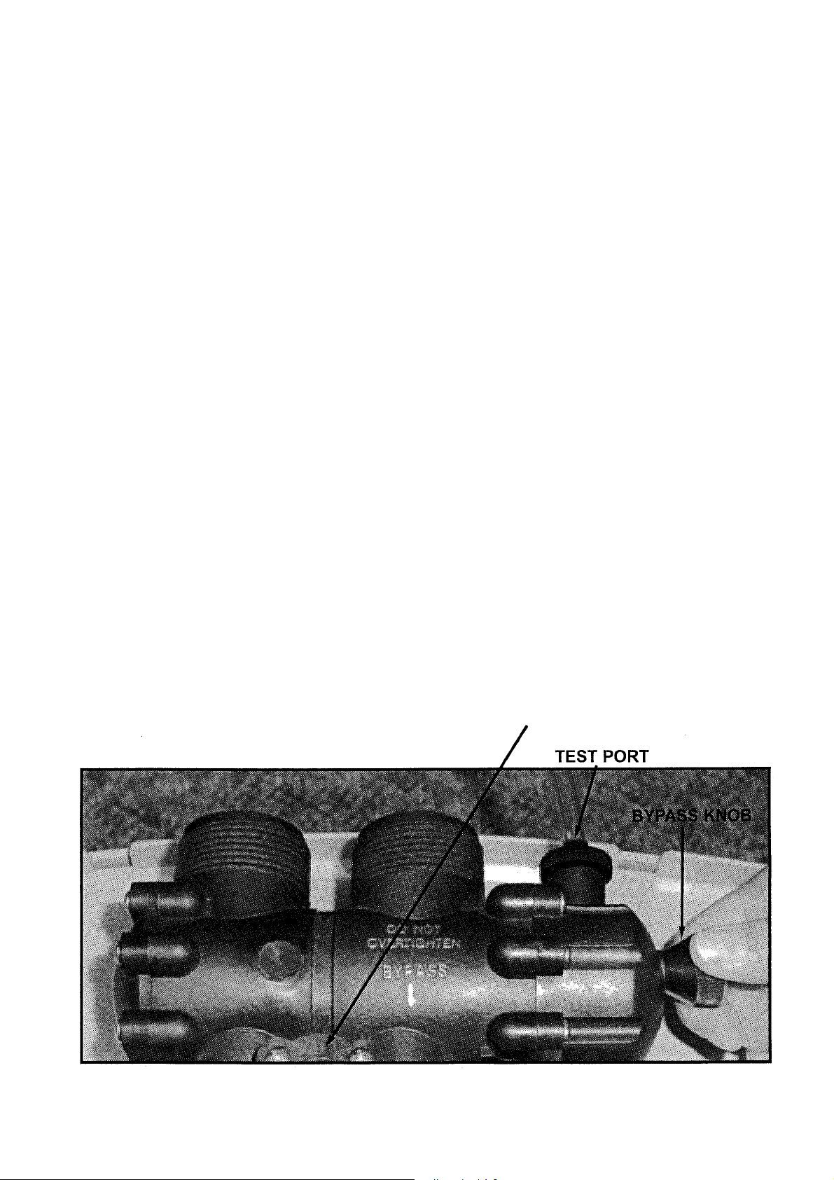
Wh en 8z How- To Use The Bypass Valve
The bypass valve is intended to provide isolation of the
system malfunction, leak, or if the use of untreated water for watering plants, shrubs, or lawns
is not available otherwise.
Facing your appliance from the front, the bypass is located on the main control valve (See '
below.) To engage the bypass, locate the cone-shaped knob on the right hand side, behind
the controller. Turn the knob counter-clockwise until it stops. Now the appliance is bypassed
and all water to the home is raw, untreated water.
To prevent untreated water from entering the home, do not use water while watering your
landscape.
clock-wise until it stops.
When watering is finished, return the appliance to service by turning the knob
WaterMax
appliance in the event of a
Blending Valve Adjustment
In some situations, a blending valve may be desired. The amount of hardness blended back
into the water line is determined by the hardness of the incoming water and the setting of the
blending valve. Where extremely hard water is present, the blending valve may only need to
be "cracked" open. Where the incoming water has relatively low levels of hardness, the
blending valve will need to be opened further. The blending valve is located between the
input and output connections on the top of the bypass valve. It is adjusted by placing a flat
blade screwdriver in the slot provided and turning clockwise to open. Total movement of the
blending valve from full closed to full open is 1/4 revolution. Precise setting of the blending
valve will require "trial and error" testing. The initial setting should be conservative. Because
of the blending valve's ease of access and adjustment, the end user can increase or decrease
the setting according to their preference over a period of time.
BLENDING VALVE
5
Page 6
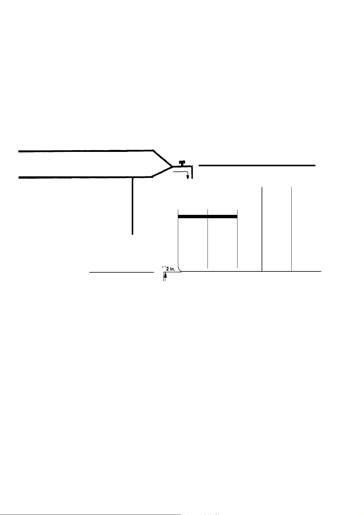
Installation Guide 8z Start-up Procedure
Figure 1
From Meter
From Well
Cold Water
Hot Water
r
Drain Line
C7WATERIIAX
Pressure Tank
Maintain a min. 2 in. air gap
Use this diagram as a location and installation guide for your
To simplify installation and servicing, your
WaterMax
appliance includes a bypass valve
60 Series
Water
Heater
r
water conditioner.
required by the uniform plumbing code. A bypass system also provides access to untreated
water when required (i.e. for lawn and gardening purposes.) See page 5.
Installation tip:
if the installation includes backfeeding the water heater for soft water service,
a minimum of 10 feet of pipe is recommended between the outlet of the appliance and the inlet
of the water heater. This reduces the potential for hot water backup into the
WaterMax.
(Check the local plumbing code for compliance.)
6
Page 7

Installation Guide & Start-up Procedure
1.
Place the 60 Series in the desired location. Turn
off the electricity and/or water supply to the water
heater.
tions meet the applicable local codes. Check the
arrows on the bypass valve to be sure the water flows
in the proper direction.
the appliance in backwards.
2.
tubing and should make the shortest run to a suitable
drain.
3.
flexible 3/8" plastic tube included with the system. Be
sure to insert the plastic insert in the end of the brine
tube. (See figure 13, page 34.) Thread the Overflow
fitting into the outside of the cabinets and tighten until
snug. Connect the Overflow Line to the brine tank. If
the brine tank is filled with too much water, or if there
is a malfunction, an overflow line will direct excess
water to the drain.
Connect 1/2" I.D. tubing (not supplied) between the
overflow fitting and a suitable waste receptor.
Maintain a minimum of 2" (50mm) air gap between
the drain line and the flood level rim of the waste
receptor to prevent back siphoning. This is a gravity
drain.
least 3" lower than the bottom of the overflow fitting.
4.
floor drain, laundry tub or other suitable waste recep-
tor.
between the drain line and the flood level rim of the
waste receptor to prevent back siphoning.
5.
turn on the main water supply. Open the nearest cold
water faucet to flush the plumbing of any excess soldering flux, air, or any other foreign material.
6.
found, turn off the main water supply and open the
nearest cold water faucet to depressurize the lines.
Close the faucet to eliminate siphoning action.
Repair leaks. Place the bypass in the "service" posi-
tion.
the WaterMax. Then open the nearest cold water
faucet to purge air out of the appliance. Close the
faucet.
Make sure the inlet, outlet and drain connec-
CAUTION: Do not plumb
The drain hose must be a minimum of 1/2" I.D.
Connect the salt tank to the valve head with the
The overflow line must end at a drain that is at
Attach the drain line. Route the drain line to a
Maintain a minimum of 2" (50mm) air gap
Place the appliance in the bypass position and
Close the faucet and check for leaks. If leaks are
Slowly open the main water supply valve and fill
7.
Connect the transformer power cord to the back of
the controller.
8.
Plug in the transformer.
9.
Program the Appliance Control. See pages 8-12.
10.
Add water to the brine tank. Fill to a minimum of
2" above the grid plate. Make sure that the salt
dosage is set as recommended for the application.
After the first regeneration, the appliance will auto-
matically refill the correct amount of water into the
brine tank.
11.
Initiate a manual regeneration and inspect for
proper operation. Allow the appliance to draw all the
water out of the brine cabinet until the air check sets.
Then advance to the Brine Refill position by using the
Regenerate button. Let the tank fill with the proper
amount of water. The controller will then step the
valve to the Home position.
12.
Fill the brine tank with salt.*
pellet with solar salt.
13.
Open the inlet valve and turn on the electricity to
the water heater. To complete the installation, open a
cold water tap and allow the appliance to flush for 20
minutes or until approximately 72 gallons have
passed through the appliance. Verify the flow rate on
the controller, indicating water flow. (See figure 2.)
14.
Make sure the bypass is left in the "service" position. Test the water at the test port to verify soft water.
(See pg. 5).
15.
Place covers on both cabinets.
*CAUTION:
chloride when iron and/or manganese is present in
the raw water supply (see pg. 2).
we do not recommend using potassium
Note:
Do not mix
7
Page 8
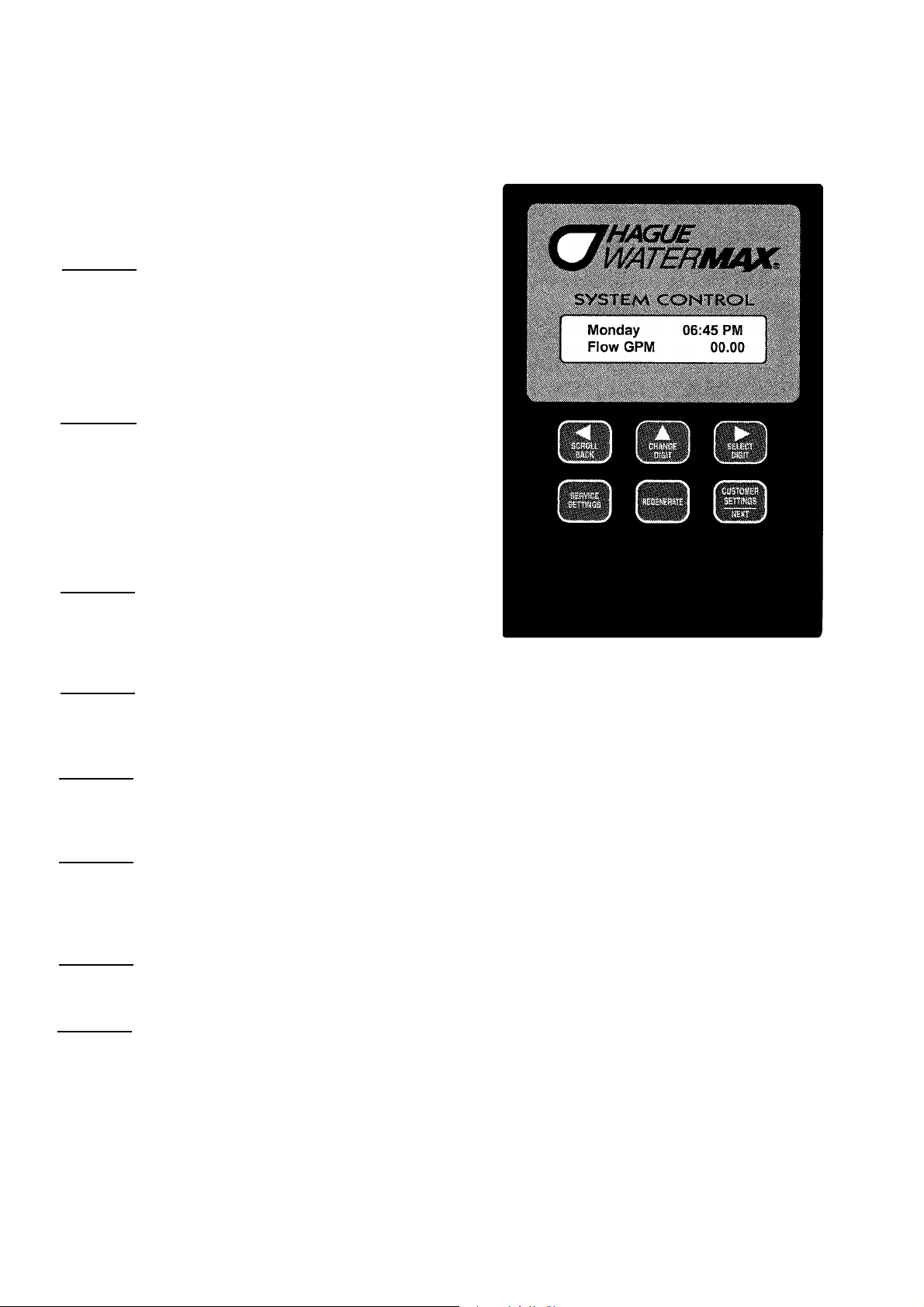
Setting And Using The Appliance Control
Figure 2
SERVICE SETTINGS
This section is recommended for qualified service personnel
only.
The appliance control must be set
correctly for proper performance.
FUNCTION:
three OPERATING MODES can be selected and all operating
parameters can be set for each OPERATING MODE when this
button is activated.
Press and hold (approximately 3 seconds) until display
changes to "Set language???". Use the NEXT button to step
through parameters that can be set.
REGENERATE
FUNCTION:
an immediate regeneration. Press and hold (approximately 5
seconds) until display changes to "Going to 1". The appliance is
now in regeneration and will return to "Gal. Remain" after completion of all cycles. 2.) Used to "speed up" or toggle through
all the regeneration cycles.
CUSTOMER SETTINGS/NEXT
This section is recommended for qualified service personnel
only.
Must be set correctly for proper performance.
FUNCTION:
SETTINGS mode. 2.) Used to "step" through parameters that
can be set in CUSTOMER & SERVICE SETTINGS modes.
Press and release to accomplish various functions.
SELECT DIGIT
FUNCTION:
with CHANGE DIGIT button. Press and release the Select Digit button to move cursor one digit to the right of parameter that
can be set.
Used to enter SERVICE SETTINGS mode. All
Multi-purpose. 1.) Used to put the appliance into
cu5Tt
s
s~rt~as
Multi-purpose. 1.) Used to enter CUSTOMER
Used to control cursor movement when in CUSTOMER & SERVICE SETTINGS modes. Used in conjunction
When cursor is at extreme right position, press again to reset cursor to extreme left position.
CHANGE DIGIT
FUNCTION:
and release the Select Digit button to move cursor one digit to the right of parameter that can be set.
extreme right position, press again to reset cursor to extreme left position.
SCROLL BACK
FUNCTION:
eliminates the need to toggle through the entire program to correct an input error.
CONTROL PANEL DISPLAY:
LCD DISPLAY
FUNCTION:
mode. It is very important to know which mode the control is in for proper operation.
WATER FLOWING INDICATOR
FUNCTION:
gallons per minute. This is useful for checking for proper plumbing and leaks.
Used to change values of parameters that can be set. Used in conjunction with SELECT DIGIT button. Press
Used to toggle back to the previous parameter setting in the event of a mistake in programming. This feature
Shows status of control; NORMAL OPERATING mode, SERVICE SETTINGS mode or CUSTOMER SETTING
Shown in the LCD display, it indicates that water is flowing through the WaterMax. Flow rate is displayed in
When cursor is at
8
Page 9

Setting And Using The Appliance Control (cont.)
Description Of The Three WaterMax Operating Modes
CAUTION:
allow the clips on the bottom of the controller case to lock onto the end cap tabs. (See detail diagram on page 20; fig. 3.)
will
MODE
TIMER MODE:
Time of regeneration can be set. To regenerate on a specific day or days of the week, set frequency to 00 for
MODE.
eliminate the days not to regenerate. Example: S
MODE 2
PATENTED SAVEMATIC - DEMAND DELAYED:
only regenerate using the amount of salt needed to maintain capacity. Time of regeneration can be set. If total capacity is
depleted before set regeneration time, a forced regeneration will occur. Appliance will regenerate again that night and then
go back to the normal setting.
MODE 3
DEMAND IMMEDIATE:
reached. Time of regeneration cannot be set.
THE FOLLOWING EXAMPLE
follow these steps, you will set a WaterMax 62 AMQ for OPERATING MODE 2, DEMAND DELAYED operation. All three
OPERATING MODES use similar procedures. Push the SERVICE SETTINGS button to enter SERVICE SETTINGS mode.
The display will show:
SETTINGS mode: ENG - English, FRA- French, ESP - Spanish, DEU - German, ITA- Italian.
1.00
2.00
2.00a
3.00
3.00a
3.01.
3.01a
3.01b
3.02
3.02a
3.03
3.03a
Be sure the controller is firmly "locked" onto the drive end cap assembly." The four tabs on top of the drive end cap
1
Will regenerate based on frequency. Example: every 2 days or as specified up to 12 days.
WEEKDAY
The display will show: Reg. Days,
Will regenerate based on water usage alone. Regeneration will occur when the capacity limit is
takes you through the steps involved for setting the WaterMax SYSTEM CONTROL. If you
Set Language ENG
Push the CHANGE DIGIT button until the correct language is displayed. In this example, set to: Set Language ENG.
Push the NEXT button to step to the next parameter. The display will show:
Push the CHANGE DIGIT button to toggle English/metric units of measure.
For this example, set to: Units ENG.
Push the NEXT button to step to the next parameter. The display will show:
to enter the History file. The History file is used as a record of water readings for future reference. (3.00 - 3.14 is
an electronic notepad only and does not affect the operation of the appliance.)
Push the CHANGE DIGIT button to toggle between Yes or No. Setting to "Yes" will enter the History file and setting
to "No" will bypass the History file. In this example, set to:
Push the NEXT button and the display will show
reset.
Push the NEXT button to step to the next parameter. The display will show:
This parameter is to be set to the installation date of the appliance. There are six digits. The first two are the
month. The next two are the day and the final two are the year. This is the first entry in the History file.
Push and release the CHANGE DIGIT button until the value above the cursor is equal to the number of the
desired Month setting.
Continue using the SELECT and CHANGE buttons until the desired date is displayed.
Example: July
Push the NEXT button to step to the next parameter. The display will show: #
is used to record the number of people in the household and should match the "# People" setting in the
CUSTOMER SETTINGS file.
Push the SELECT and CHANGE buttons until the desired number of people in the household is reached.
In this example, set to: #
Push the NEXT button to step to the next parameter. The display will show:
This parameter is used to record the tested Hardness of the water.
Push the SELECT and CHANGE buttons until the desired hardness number is reached.
In this example, set to:
24, 2002=072402 (Hist)
People 004 (Hist)
Hard. Or. 025 (Hist)
MTWTF S. To select the day(s), simply use the select and change buttons to
W F.
Is based on actual water usage and total capacity of the appliance.
This parameter is used to set the language that is displayed in the CUSTOMER
Units ENG
This parameter is used
Inst. Date 000000 (Hist)
This parameter
History Yes
Soft. V# 1.01
(Hist).
History NO
This is information only and cannot be
People 000 (Hist)
Hard. Or. 000 (Hist)
Will
9
Page 10

Setting And Using The Appliance Control (cont.)
3.04
3.04a
3.05
3.05a
3.06
3.06a
3.07
3.07a
3.08
3.08a
3.09
3.09a
Push the NEXT button to step to the next Parameter. The display will show:
This parameter is used to record the tested iron content of the water.
Push the the SELECT and CHANGE buttons until the desired iron number is reached.
In this example,
Push the NEXT button to step to the next Parameter. The display will show:
This parameter is used to record the tested Manganese content of the water.
Push the SELECT and CHANGE buttons until the desired manganese number is reached.
In this example, set to:
Push the NEXT button to step to the next Parameter. The display will show:
This parameter is used to record the tested chlorine content of the water.
Push the SELECT and CHANGE buttons until the desired chlorine number is reached.
In this example, set to:
Push the NEXT button to step to the next Parameter. The display will show:
This parameter is used to record the tested sulfur content of the water.
Push the SELECT and CHANGE buttons until the desired sulfur number is reached.
In this example, set to:
Push the NEXT button to step to the next parameter. The display will show:
This parameter is used to record the tested pH of the water.
Push the SELECT and CHANGE buttons until the desired pH number is reached. In this example,
set to:
Push the NEXT button to step to the next parameter. The display will show:
This parameter is used to record the presence of iron bacteria in the water.
Push the SELECT and CHANGE buttons until the desired word is reached. In this example,
set to:
pH 07.0 (Hist)
Iron Bact. NO (Hist)
set to: Iron ppm 002 (Hist)
Mang. ppm 000 (Hist)
Chlor. ppm 000 (Hist)
Sulfur ppm 000 (Hist)
Iron ppm 000 (Hist)
Mang. ppm 000 (Hist)
Chlor. ppm 000 (Hist)
Sulfur ppm 000 (Hist)
pH 00.0 (Hist)
Iron Bact YES (Hist)
3.10
3.12a
3.14.
4.00
5.00
Push the NEXT button to step to the next parameter. The display will show:
This parameter is used to record the total number of regenerations the appliance has gone through and cannot
be reset.
Push the NEXT button to step to the next parameter. The display will show: Tot.
This parameter is used to record the total number of gallons of water that has passed through the appliance and
cannot be reset.
Push the NEXT button to step to the next parameter. The display will show:
This parameter is used to record the model number of the appliance.
Push the SELECT and CHANGE buttons until the desired model number is reached.
In this example, set to:
Push the NEXT button to the next parameter. The display will show:
This parameter, if set to YES, will save the current information you have just entered. If set to NO, it will leave the
History file as previously defined.
Push the CHANGE DIGIT button to toggle between Yes or No. In this example, set to:
Push the NEXT button to step to the next parameter. The display will show: Tot. Regens. 00000
This parameter displays the number of regenerations the appliance has gone through since the last time the
SERVICE SETTINGS mode was entered. This parameter is reset to 00000 after exiting the SERVICE SETTINGS
mode. Push the NEXT button to step to the next parameter. The display will show: Tot. Gal. 00000000
This parameter displays the Total Gallons the appliance has gone through since the last time the SERVICE
SETTINGS mode was entered. This parameter is reset to 00000000 after exiting the SERVICE SETTINGS mode.
Push the NEXT button to step to the next parameter. The display will show:
of the OPERATING MODE for which the system control is set.
Model#62AMQ (Hist)
Tot.
Regens. 00000 (Hist)
Gal. 00000000 (Hist)
Model#00AAA (Hist)
Save History YES
Mode 2
The "Mode #" is the number
Save History
YES
5.00a
Push the CHANGE DIGIT button to change the value of "Mode #" until it reads 2 (for this example.)
10
Page 11

Setting And Using The Appliance Control (cont.)
6.00.Push the NEXT button to step to the next parameter. The display will show:
hardness number of the water tested. This number is to be the actual hardness reading and is not
compensated for iron.
6,OOa
6.00b
L
7.00a
8.00
8.00a
8.00b
8.00c
Push and release the SELECT DIGIT button until the cursor ( )ispositioned in the display as follows:
Hard. Gr. Q40.
Continue pushing the SELECT and CHANGE buttons until the desired hardness number is displayed.
Example: Hard. Gr. 025
Push the NEXT button to step to the next parameter. The display will show:
This parameter is used to calculate a compensated hardness automatically.
Push the SELECT and CHANGE buttons until the desired iron number is displayed.
Example:
Push the NEXT button to step to the next parameter. The display will show:
Push the SELECT and CHANGE buttons until the desired manganese number is displayed.
Example:
Push the NEXT button to step to the next parameter. The display will show:
WARNING!
chloride as a regenerant. Iron and/or manganese bacteria may develop and foul the conditioning media and may
void the warranty.
Push the SELECT and CHANGE buttons until the desired regenerant is selected. EXAMPLE: Salt = Sodium.
The cursor is now under the "ten" position.
Iron ppm 02
Mang. ppm QO
When iron and/or manganese is present in the water supply, we do not recommend using potassium
Hard. Gr. 040
Iron ppm 00
Mang. ppm 00
SALT=Sodium.
The 040 is the
9,00
10.00
10.00a
11.00
11.00a
12.00
12.00a
13.0
Push the NEXT button to step to the next parameter. The display will show:
This parameter is the calculated compensated hardness using the hardness, iron and manganese settings.
The formula is (4 x each ppm iron) + (4 x each ppm manganese) + hardness = compensated hardness.
This is not a parameter that can be set. The display should now read:
Push the NEXT button to step to the next parameter. The display will show:
This parameter is used to set the softening capacity of the appliance. (See WaterMax engineering specifications
or setting charts for capacities based on salt usage.)
Push the SELECT and CHANGE buttons until the desired capacity number is displayed.
In this example, set to:
Push the NEXT button to step to the next parameter. The display will show:
This parameter, if set to "Yes", is used to force the appliance to regenerate every 96 hours if regularly scheduled
regenerations based on water usage do not occur in 96 hours or less intervals. This should always be "yes" if iron
is present in the water.
Push CHANGE button to toggle parameter value from "No" to "Yes". In this example, set to:
Push the NEXT button to step to the next parameter. The display will show: Distill/RO
Set this parameter to "Yes" if a distiller or reverse osmosis system is plumbed to use soft water from
the WaterMax.
Push the CHANGE button to toggle parameter value from "No" to "Yes". In this example, set to: Distill/RO
Push the NEXT button to step to the next parameter. The display will show:
(See WaterMax setting chart.) The "01.0" is the time, in minutes to the nearest tenth, for which the first backwash
cycle can be set.
Capac. Gr. 28730
Comp. Hard. 00033
Comp. Hard. 00033
Capty. Gr. 28730
72-96hr Regen Yes
96hr Regen Yes
Yes
Yes
Backwash1Q1.0
13.00a
Push the SELECT and CHANGE buttons until the desired backwash time is displayed.
In this example, set to:
Backwash 1 07.0
11
Page 12

Setting And Using The Appliance Control (cont.)
14.00
14.00a
15.00
15.00a
16.00
16.00a
17.00
17.00a
18.00
18.00a
19.00
Push the NEXT button to step to the next parameter. The display will show:
The "30.0" is the time, in minutes to the nearest tenth, for which the first brine and slow rinse cycles can be set.
Push the SELECT and CHANGE buttons until the desired combined brine and slow rinse cycle time is displayed.
In this example, set to:
Push the NEXT button to step to the next parameter. The display will show:
The "05.0" is the time, in minutes to the nearest tenth, for which the second backwash can be set.
Push the SELECT and CHANGE buttons until the desired backwash time is displayed.
In this example, set to:
Push the NEXT button to step to the next parameter. The display will show:
This parameter sets the amount of salt to be used to achieve the capacity setting. Remember, in OPERATING
MODE 2, WaterMax only uses as much salt as is needed to maintain the capacity setting.
Push the SELECT and CHANGE buttons until the desired salt setting is displayed.
In this example, set to:
Push the NEXT button to step to the next parameter. The display will show: Turbine
This feature should only be used by qualified service personnel. It is intended to be used for diagnostic purposes
only.
WARNING! Do not engage this feature.
Push the SELECT and CHANGE buttons until the correct value is displayed.
In this example, set to:
Push the NEXT button to step to the next parameter. The display will show:
This parameter, if set to YES, will force a regeneration at the next set regeneration time (i.e. 02.00.) After the
regeneration, the parameter will automatically reset to "No."
Push the CHANGE DIGIT button to toggle between Yes or No. In this example, set to:
Push the NEXT button to step to the next parameter. The display will show:
Gal. Remain 000871
Brine/Rinse 30.0
Backwash 2 02.0
Salt lbs 06.2
Turbine Test NO
Brine/Rinse 30.0
Backwash 2 05.0
Salt lbs. 06.2
Test NO
Reg. Tonight NO
Reg. Tonight YES
1.00
1.00a
2.00
2.00a
3.00
3.00a
4.00
4.00a
5.00
This is the normal operation display for OPERATING MODE 2. The 00871 represents the number of gallons of
softening capacity between regenerations. This completes the SERVICE SETTINGS mode.
Even though the SERVICE SETTING mode has been completed, the WaterMax is not ready for service until the
.
CUSTOMER SETTINGS mode is completed. The following example takes you through the steps required for
setting the parameters of the CUSTOMER SETTINGS mode for OPERATING MODE 2.
Push and hold the Customer Settings/Next button to enter CUSTOMER SETTINGS mode. The display will show:
Set Time 00:00 AM
Push the SELECT and CHANGE buttons until the desired time is displayed.
In this example, set time to: Example: 11:00 AM or 05:00 PM.
Push the NEXT button to step to the next parameter. The display will show:
This parameter is to be set for the desired time a normally scheduled regeneration is to occur.
Push the SELECT and CHANGE buttons until the desired time is displayed.
In this example, set to: Reg. Time 02:00. (02:00 is 2:00am)
Push the NEXT button to step to the next parameter. The display will show: #People 04
Push the CHANGE button until the correct number of people in the household is displayed.
Push the NEXT button to step to the next parameter. The display will show: SET DAY.
Push the CHANGE button until the correct day of the week is displayed.
Push the NEXT button to save the parameter settings and exit the CUSTOMER SETTINGS mode.
The display will show:
If you followed the above directions correctly, your
is ready for OPERATING MODE 2 service.
This parameter is to be set to the current time of day.
Reg Time 02:00 AM
Gal Remain 00871
WaterMax Systems Control
12
Page 13

F4,11gineering Specifications
60 SERIES
Tannin (ppm)
Sulfur (ppm) - SulfurStat
Iron (ppm) - ferrous - clear water •
Maximum Compensated Hardness
Maximum Chlorine (ppm)
Minimum pH
Filtration - nominal rating (microns)
#1 Salt - 5850 grains per lb of salt (Ibs./capacity)
#2 Salt - 5163 grains per lb of salt (Ibs./capacity)
#3 Salt - 4679 grains per lb of salt (Ibs./capacity) 6.2/28,730
#4 Salt - 3828 grains per lb of salt (Ibs./capacity)
Media Amount Compartment #1
Media Amount Compartment #2 Empty
Media Amount Compartment #3
Drain Line Flow Control (gpm)@ min. water presure
Brine Line Flow Control Refill (gpm)
Water Pressure (min-max psi)
Flow Rate @ 25 psi drop
Flow Rate @ 15 psi drop#
Pressure Drop @ Flow Rate Of 4 gpm
(#1 Salt setting) total length of reg. Min / gal
(#2 Salt setting) total length of reg. Min / gal
(#3 Salt setting) total length of reg. Min / gal
(#4 Salt setting) total length of reg. Min / gal
Shipping weight (Ibs.)
63MAQ 63BEQ*
0 0
0
0
90
1
NA NA
20
1/5,850
2.7/13,890
9.3/35,300
1.5 lbs. 2.0 lbs. 1.5 lbs. 1.5 lbs.
1.06 cu.ft.
2.41'
.5
20-120
19.5 19.5
11
6.5 psi
12/13.5
18/16.5
38/26.5 38/29.5
56/35.5
135 152 168
63MXQ
0
0
90
3
25 20 20 20 20 20 20
1/5,850
2.7/13,890
6.2/28,730
9.3/35,300
.4 cu.ft.
1.06
cu.ft.
3t
.5
20-120
13
8.5 psi 8.5 psi
12/16
18/19
56/38
110
1.6/9,360 NA
4.2 /21,680
9.6/44,840 8.5/28,730 6.2/28,730 6.2/28,730 6.2/28,730 6.2/28,730
14.4/55,090
.6 cu.ft. .3 cu.ft.
1.06 cu.ft.
2.4t 2.4t
20-120 20-120
10.5 10.5 11.2 10.6 10.6 12.5
12/13.5
26/20.5
58/36.5
74/44.5 64/39.5
63MDQ
0
0 0 0
12
0 0 0
7
NA
10.7/35,300
1.06 cu.ft
.5
17 17 23
8.5 psi 3.2 psi
47/31 38/37 44/80 44/80 44/80
152 140
62AMQ
0-2
0
90tt
7 7
.5 .5 .5 .5 .5
NA
NA
12
1/5,850
2.7/13,890
9.3/35,300 9.3/35,300
NA
6 Ibs.
1.06
20-120
12/24
18/27
58/56
**62APQ***
0 0 0
0-5**
2-12**
90
0
7
NA NA
NA NA
NA NA NA
27 Ibs. .4 cuft.
1.06 cu.ft.
cuff.
5t
Empty***t
30-120 30-120
19.6 19.6 20.5
6 psi
NA
NA NA
61/89
167 160 180
62AKQ
0 0
15
90 90 60
0 0
7
9.3/35,300 9.3/35,300
1.06
cuff.
7t
6 psi 7 psi
NA NA
61/89
62AJQ****
0
5
6.3
NA
2.7/13,890
.4
cu.ft.
1.06 cu.ft.
7t
30-120
23/70
61/89
Bacteriostatic - KDF® Process Media - Listed
With The U.S. EPA As A Bacteriostatic Device.
U.S. EPA #54369-OH-001
Valve Inlet/Outlet 1"
Drain Line (Minimum ID.)
Water Temperature (Min-Max) 40-120 °F
Height (inches) 38-1/4"
Floor Space (inches) 15" x 30"
Salt storage capacity: 200 Ibs, 90kg
Brine & Rinse total: .65 gpm
Brine Draw: .25 gpm
Rinse: .4 gpm
Electrical rating: 115V, 60 cycle.
Iron Reduction To .3 ppm Or Less.
When Adding Media In The Field, Check For Proper Settings
(See Specifications, Above.)
Regeneration Every 96 Hours Is Required When Iron Is
Present In The Raw Water Supply. Use Salt Setting #3 Or #4.
*Municipally Supplied Chlorinated Water Only.
%Y "
YES
YES YES YES YES YES
**Must Have A Minimum of 2 ppm Iron and a Minimum
of 200 ppm TDS.
***This model Has No Backwash Flow Control Button Or
Retainer.
Available For Proper Backwash.
****Calcite
Softening.
tRate Of Flow Must Be Verified At The End Of
Drain Line.
An
tt
Of Calcium Carbonate Precipitation. As The
Hardness Increases So Does The Chance Of This
Precipitation.
Along With Salt.
Must Have A Minimum Of 7 gpm @ 30 psi
Will Add Additional Hardness To Water Before
y Hardness Over 10 gpg Will Increase The Chance
Must Use Citric Acid to Regenerate
13
YES
YES
"
%Y
ID
Page 14
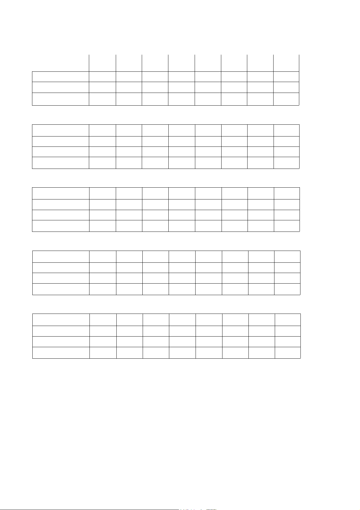
Mode I Setting Chart
60 SERIES
Mode1
Regeneration
Frequency
96 hour regeneration
iron present – yes)
(if
#1 SALT SETTING
Backwash 1 (minutes)
Brine rinse (minutes)
Backwash 2 (minutes)
Capacity
t .
salt lbs.
#2 SALT SETTING
Backwash 1 (minutes)
Brine rinse (minutes)
Backwash 2 (minutes)
Capacity
0. salt Ibs.
63MAQ
YES YES
As
requiredAsrequired
•
--
1 1 1
7
3 3
5,850
1
lb.
1
12
3 3
13,890
2.7 lbs.
63BEQ*63MXQ
YES YES
As
required
–
7
5,850
1 lb,
1
12
13,890
2.7 lbs.
YES
7
3
9,360
1.6 lb.
S
1
19
3
21,680
4.2 lbs.
63MDQ
1
or 2
--
—
—
—
-
62AMQ
YES
As
required
YES YES YES
5,850
1 lb.
12
13,890
2.7 Ibs,
2 •
7
2
2
2
62APQ
**
***
YES
1
or 2
--
--
---
-- --
–
---
---
—
62AKQ
YES YES
1
or 2
—
---
--
--
--
--
--
62AJQ
****
or 2
1
YES
—
–'
---
—
7
S
12
2
13,890
2.7 lbs.
#3 SALT SETTING
Backwash 1 (minutes)
Brine rinse (minutes)
Backwash 2 (minutes)
Capacity
0. salt lbs.
1 1
30
3
28,730
6.2
lbs.
30
3
28,730
6.2 lbs.
1tt
47
3 3
44,840
9.6
Ibs.
1
38 30
28,730
8.5
Ibs.
2tt
2
28,730
6.2
lbs.
7 7
30
2
28,730
6.2
lbs.
30
2
28,730
6.2
Ibs.
7
30
2
28,730
6.2 Ibs.
#4 SALT SETTING
Backwash 1 (minutes)
Brine rinse (minutes)
Backwash 2 (minutes)
Capacity
LDsalt Ibs.
1
45
3
35,000
9.3 Ibs.
1
45
3
35,000
Ibs.
9.3
Itt
60 52
3
55,090
14.4 Ibs.
1
3
35,000
10.7 Ibs.
4tt
45 45
2 2
35,000
9.3
lbs.
7
35,000
9.3
Ibs.
*Municipally supplied chlorinated water only.
**Must have a minimum of 2 ppm iron and a minimum of 200 ppm TDS. See Engineering Specifications.
***Unit has no backwash flow control button or retainer. Must have a minimum of 7 gpm@30 psi available for proper backwash.
****Calcite will add additional hardness to water before softening.
'If iron is present in water supply, use salt setting #3 or #4.
ttlf iron is present in the water supply, set #1 backwash to 7 minutes.
7 7
45 45
2 2
35,000
9.3
lbs.
35,000
9.3
Ibs.
14
Page 15
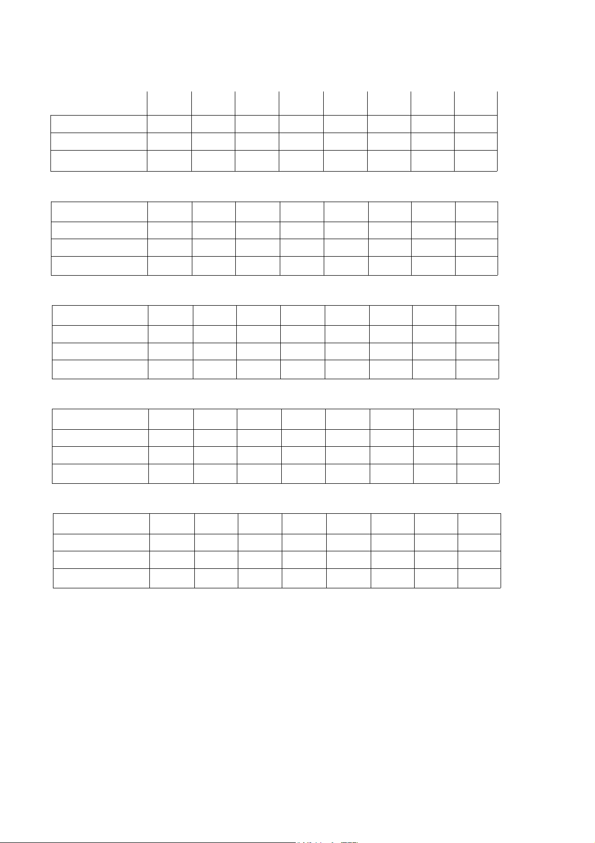
Mode II Setting Chart
60 SERIES
Mode 2
Capacity
63MAQ
required
96 hour regeneration
Iron present – yes)
(If
YES OR
•
#1 SALT SETTING
Backwash 1 (minutes)
Brine rinse (minutes)
Backwash 2 (minutes)
Capacity
5,850
fa. salt lbs.
#2 SALT SETTING
Backwash1(minutes)
Brine rinse (minutes)
Backwash 2 (minutes) 3
Capacity
salt tbs.
13,890
2.7 lbs.
63BEQ
*
YES YES
As
As
required
YES OR
NO NO
1
7
3
5,850
1 lb.
1 lb.
1
12
12
13,890
2.7 lbs.
63MXQ
YES
As
required
YES OR
NO
1 1
7 7
3 3
9,360
1.6 lb.
1
3
21,680
4.2 lbs.
19
63MDQ**62AMQ
NO
--
•
1
•
3
—
—
--
—
—
—
—
—
YES
As
required
YES OR
NO
2
•
7
2
5,850
1 lb.
2 •
12
2
13,890
2.7 lbs.
62APQ
** .***
NO NO
62AKQ
**
— —
—
--
—
—
—
'–
-- --
–'
— — —
—
—
—
--
— —
62AJQ
****
YES
As
required
YES OR
NO
-`
—
7 •
12
2
13,890
2.7 lbs.
#3 SALT SETTING
1
Backwash
(minutes)
Brine rinse (minutes)
Backwash 2 (minutes)
Capacity
(
salt lbs.
1
30
3
28,730
6.2 lbs.
1
30
3 3
28,730
6.2 lbs.
Itt
47
44,840
9.6 lbs.
—
—
—
—
2tt
30
2
28,730
6.2 lbs.
—
—
—
— —
—
—
--
7
30
2
28,730
lbs.
#4 SALT SETTING
Backwash 1 (minutes)
Brine rinse (minutes)
Backwash 2 (minutes)
Capacity
(aa
salt tbs.
1
45
3
35,300
9.3
lbs.
1
45
3 3
35,300
9.3 lbs.
It t
60
55,090
14.4 lbs.
—
—
—
4tt
45
2
35,300
9.3 lbs.
--
—
--
—
—
—
--'
—
*Municipally supplied chlorinated water only.
**NA, see Mode 1 Setting Chart.
***Unit has no backwash flow control button or retainer. Must have a minimum of 7 gpm@30 psi available for proper backwash.
****Calcite will add additional hardness to water before softening.
*If iron is present in water supply, use salt setting #3 or #4.
ttlf iron is present in the water supply, set #1 backwash to 7 minutes.
7
45
2
35,300
9.3 lbs.
15
Page 16
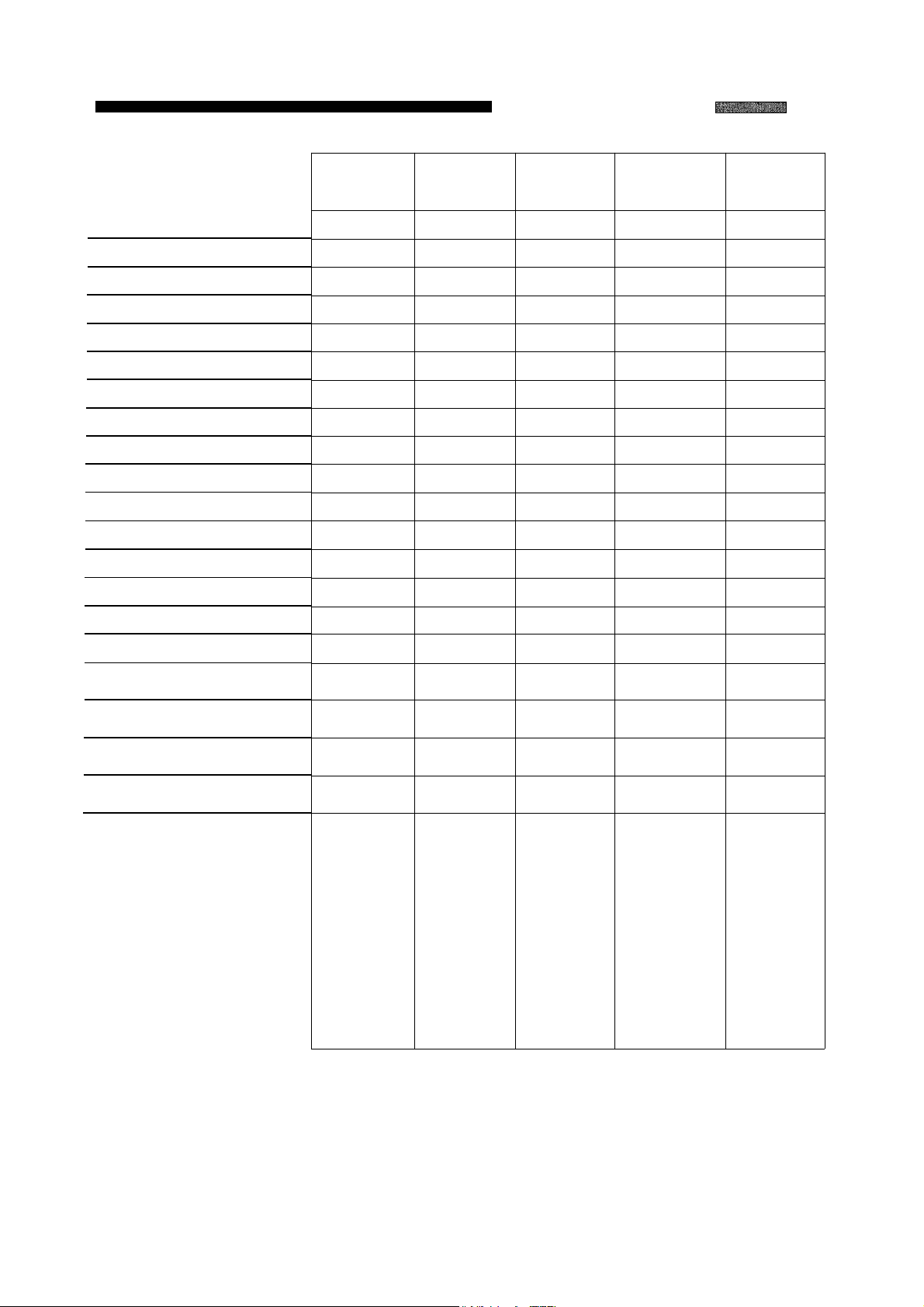
WaterMax Filters
WaterMax Filters
Application Chart
Capacity (ppm)
Sulphur H2S
Iron (ppm)
Minimum pH
Media type
Media amount (cu. ft.)
Cont. flow rate (gpm)
Peak flow rate (gpm)
Backwash rate (gpm)
Brine line flow control (gpm)
Water pressure
Mode settings
Backwash #1 (min)
Brine/rinse (min)
Backwash #2 (min)
(2 ppm)
61 AAN
10,000
5
20
7
Manganese
Greensand
1.25
61 AAE
-BWO
61 AAR
-BWO
N/A N/A N/A
N/A N/A N/A N/A
N/A
N/A
Activated Carbon
1
N/A N/A
N/A
Filter Ag
1.25 1.25
61 AAS
-BWO
'
5
Calcite/Corsex
6 6 6 6 6
10 10
7
.5
5 5
N/A N/A N/A N/A
30-120 30-120
1 1 1
5
7
10
30-120
7 7
10 12
7 7
30-120 30-120
1
45 0 0 0 0
3
0 0
0
61 AAF
-BWO
N/A
N/A
N/A
multi-Grade
1
1
7
0
Salt (lbs.
3 b. a It setting=4oz. KMnO4
Regenerant used
Flow rate at 25 PSI drop
Flow rate at 15 PSI drop
Recommended service flow
pressure drop
1
The 61AAS-BWO will raise the pH of most, but not all low pH water. Some water requires
chemical injection using a chemical feed pump.
2
3
CAUTION: follow the instructions on the KMnO4 container.
For optimum water quality, do not exceed recommended service flow rate for filter media type.
2
3
4 oz.
0 0
N/A
N/A
0
0
N/A N/A
KMnO4
3
@
16.7 GPM 21.4 GPM 21.5 GPM 20.4 GPM
10.5 GPM
4.5 GPM @
4.7 PSI
Removes iron
and iron
Also removes
up to 5 ppm
Hydrogen
Sulfide with
the presence
of 2 ppm iron.
Regenerate
every 6 days
for iron; as
needed for
Hydrogen
Sulfide
(sulfur),
algae.
15.9 GPM 15.9 GPM 15.2 GPM 15.1 GPM
3.6 GPM @
1.1 PSI
Removes
tastes, odors
and will reduce
most manmade
pollutants.
Backwash
every 3 days
orasneeded.
WARNING!
Must not be
Must not
backwash ed
for 24 hours
after
installation.
4.5 GPM @
1.5 PSI
Removes Will
suspended pH of most low
matter
(turbidity) from mineral media
water down to
the 20-40
micron range.
Backwash
every 3 days optimum bed
orasneeded.
4.5 GPM @
1.8 PSI
raise the Removes
pH water. The
must be
replenished nominal 20
periodically to
maintain
depth for or as needed.
effective
correction.
Backwash
every 2 days to
prevent
solidification of
19.4 GPM
3.6 GPM @
1.5 PSI
suspended
matter
(turbidity) from
water down to
microns.
Backwash
every 3
days
16
Page 17

Troubleshooting
Problem
No soft water after regeneration.
Cause
No salt in brine tank.
Sediment in brine tank has plugged
the brine line and/or air check. (See
Fig. 4.)
Refill flow control is plugged. (See
Fig. 9.)
Drain line is pinched, frozen or
restricted. (See Fig. 1.)
Clogged injector assembly.
(See Fig. 6.)
Salt bridge has formed
Solution
Add salt.
Remove the brine line and flush
clean. Clean air check. Clean brine
tank.
Remove brine piston housing and
clear debris from the flow control.
Straighten, thaw or unclog the drain
li
ne.
Remove injector cap and clean nozzle and throat withawooden tooth-
pick.
Replace throat if removed.
High humidity or the wrong kind of
salt can create a salt bridge. This is
a crust that forms an empty space
between the water and salt. To test,
use a blunt object like a broom han-
dle.
Push the handle into the salt to
dislodge the salt bridge.
No soft water.
No flow is indicated when water
is flowing.
The plumbing bypass valve is in the
the bypass position (See pg. 5.)
Appliance is plumbed in backwards.
(See Fig. 1.)
Extended power outage.
Water hardness has increased.
Not metering water.
Blending dial is open.
The bypass valve is in the
the bypass position (See pg. 5.)
Appliance is plumbed backward.
(See Fig. 1.)
Sensor not receiving signal from
magnet. (See Fig. 7.)
Place bypass valve in the service
position.
Check that appliance is plumbed
properly.
Reset time. (See Customer
Settings.)
Reset water and reset hardness.
(See Installation Record.)
Flow should be indicated with water
usage. If no flow, see below.
Make sure blending dial is closed.
Place bypass in the service position.
Check that appliance is plumbed
properly.
Remove sensor from bypass housing.
Test with magnet on each flat side of
sensor.
the other will not. If flow is indicated,
check turbine. If no flow, replace
sensor.
One side should indicate flow.
Turbine is jammed. (See Fig. 7.)
17
Remove bypass valve and clear debris
from turbine.
Page 18

Troubleshooting
Problem
Flow indicator blinks when water
is not being used.
No read-out in display.
Appliance stays in regeneration.
C4cle display remains "going to
(Fig. 2)
Cause
There is a leak in your household
plumbing system.
Electric cord is unplugged.
No electric power at outlet.
Defective transformer (fig. 3).
Defective circuit board.
High ambient temperature.
perature exceeds 120°F, display will
blank out. This does not affect the
operation of the controller.
Defective magnet disk.
Foreign object in valve body.
If tem-
Solution
Repair the leak.
Plug in transformer.
Check power source. Make sure outlet is not controlled by a switch.
Test with volt meter for 12 VAC at
control. If less than 10 VAC or
greater than 14 VAC, replace transformer.
With 12 V AC present at control,
replace computer control.
See Enginerring Specifications,
page 13.
Replace magnet disk. (See Fig. 8)
Remove foreign objects from valve
body.
(See Fig. 5)
(Fig. 1.)
Excess water in brine tank.
Not regenerating in proper sequence.
Broken valve assembly. Motor running.
Magnet disk not turning.
Restricted, frozen or pinched drain line.
(See Fig. 1)
Plugged brine line, brine line flow
control or air check (See Fig. 9)
Plugged injector assembly.
(See Fig. 6)
Sticking brine refill valve. (See Fig. 9)
Defective magnet disk.
Defective controller.
Repair drive end cap. (See Fig. 8)
Remove restriction, thaw or straighten
drain line..
Clean flow control, air check and
brine line.
Clean or replace injector assembly.
Replace throat if removed.
Remove brine valve. Lubricate piston
with silicone grease and reassemble.
Replace magnet disk. (See Fig. 8)
Replace controller.
(See Fig. 12)
(See Fig. 3)
18
Page 19

Troubleshooting
Problem
Salty water
Cause
Plugged injector.
Low water pressure.
Drain line or flow control is restricted.
Brine line restricted or crimped.
Excessive amount of water in
cabinet.
Insufficient
Intermittent pressure drop from feed
source.
rinse time.
Solution
brine
Clean injector screen, nozzle and
throat (See
Maintain minimum pressure of 30
(See
Remove restriction.
Remove restriction, replace
crimped.
Verify correct water level relative
salt setting.
tings for
Brine Cabinet Data, page 36.)
Check mode setting chart (pg. 14-
15) for proper brine rinse time.
Adjusttime, if
Install check
li
ne to the appliance.
plumbing
Fig. 6)
Engineering
Check brine line and fit-
loose
necessary.
valve on the inlet water
codes first.)
Specs.)
if
connections (See
(Check
local
psi
to
NOTES:
19
Page 20
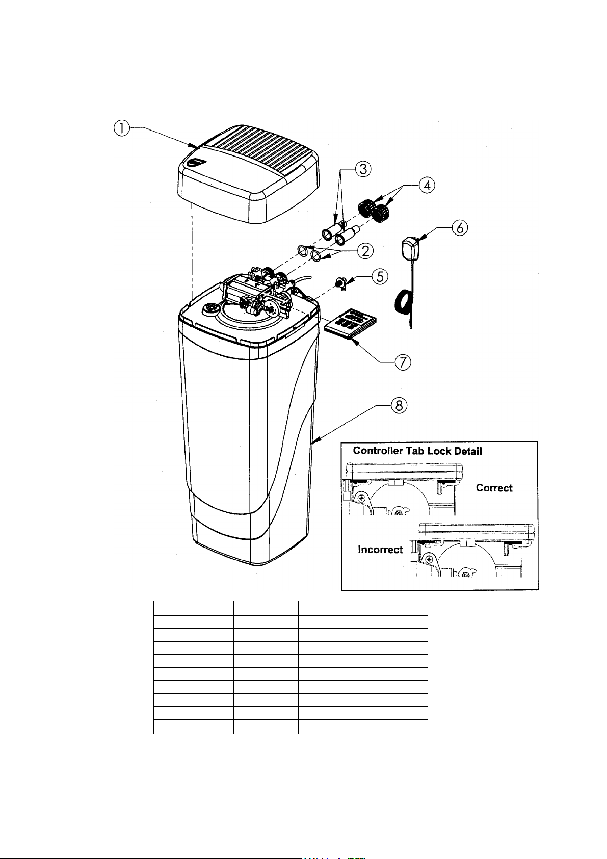
Parts -
Figure 3-HOOK-UP/COVER ASSEMBLY
ITEM NO. QTY.
1 1
2 2
3
4 2
5
6
7
8
2
2
1
1
1
1
PART NO.
54501
90837
90254
90256
90251
C0700A
93245
54500
54003
DESCRIPTION
Media Cabinet Cover Assembly
Bypass Nut Gasket
Copper Adapter
PVC Adapter (optional)
Bypass Nut
Cabinet Overflow
12V Transformer/Power Cord
6 Button Control Assembly
Cabinet
20
Page 21
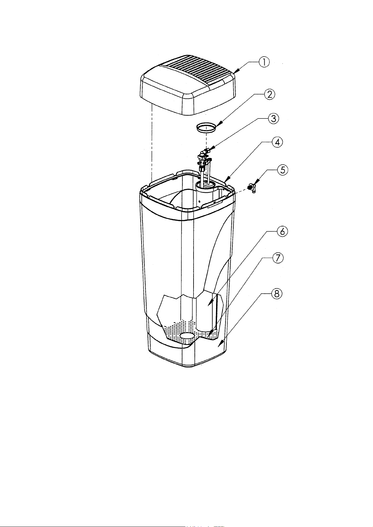
Parts —
Figure 4-BRINE TANK ASSEMBLY
PART#
1
54006
2
90103 Brine Well Cap
3
54525
4
54007
5
CO700A
6
54008
7
54009
8
54003
54509
DESCRIPTION
Brine Tank Cover
Safety Shutoff Assembly
Support Panel (BT)
Cabinet Overflow
Brine Well
Grid Plate
Cabinet
Brine Tank Assembly
QUANITY
1
1
21
Page 22
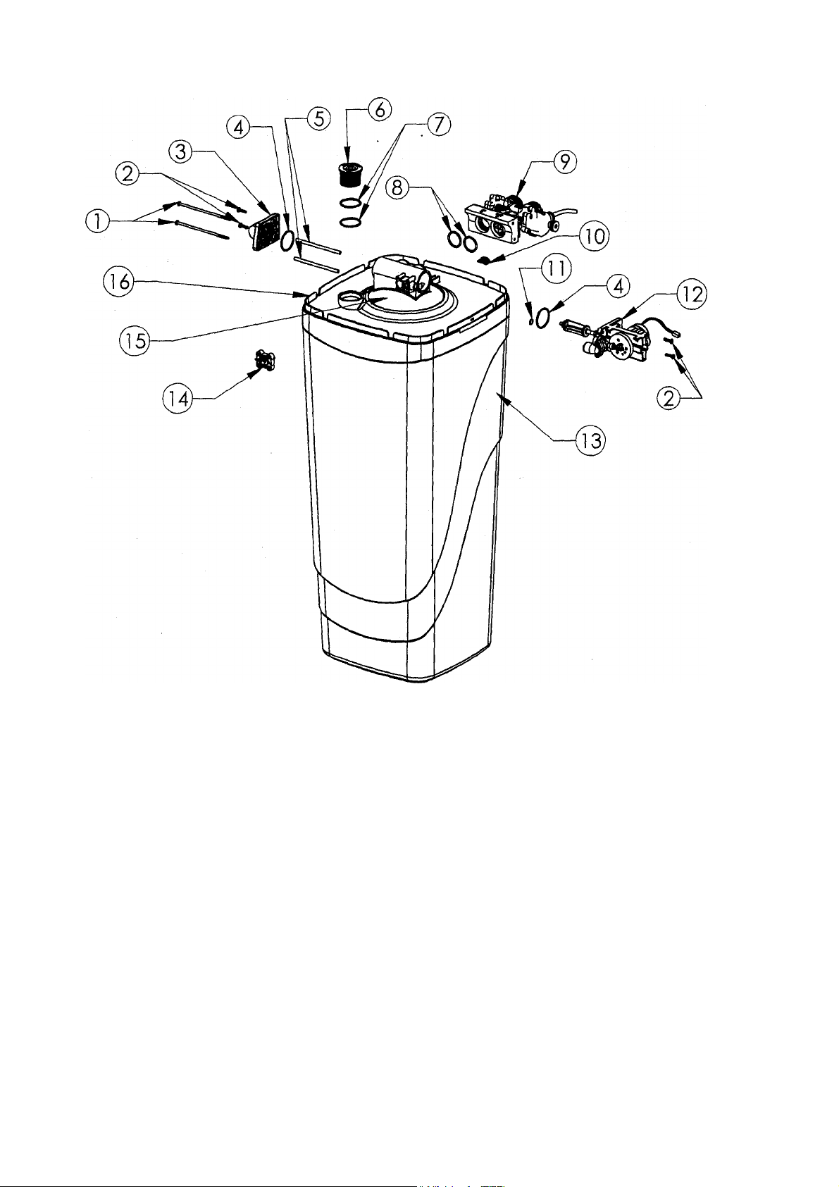
Parts –
Figure 5-Tank/Cabinet Assembly
PART#
1
93809
2
93870
3
90614
4
93808
5
93835
6
90238
7
90819
8
93838
9
90615 Bypass Assembly
10 93833
11
90828
12 95301T-JG
95302T-BWO
13 54003
14 93501
15 54508
54514
54516
16 54005
DESCRIPTION
Screw
Screw
Drian End Cap Assembly
0-Ring
Sleeve
Resin Tank Fill Plug
Fill
Plug 0-Ring
0-Ring
Cord Clip
0-Ring
Drive End Cap Assembly
Drive End Cap Assembly, Backwash Only
Cabinet
Injector Assembly
Resin Tank (3 Compartment)
Resin Tank (2 Compartment) Center & Bottom Screen
Media Tank (1 Compartment) Bottom Screen
Support Panel
QUANITY
2
4
1
2
2
1
2
2
1
1
1
1
1
1
1
1
1
1
22
Page 23
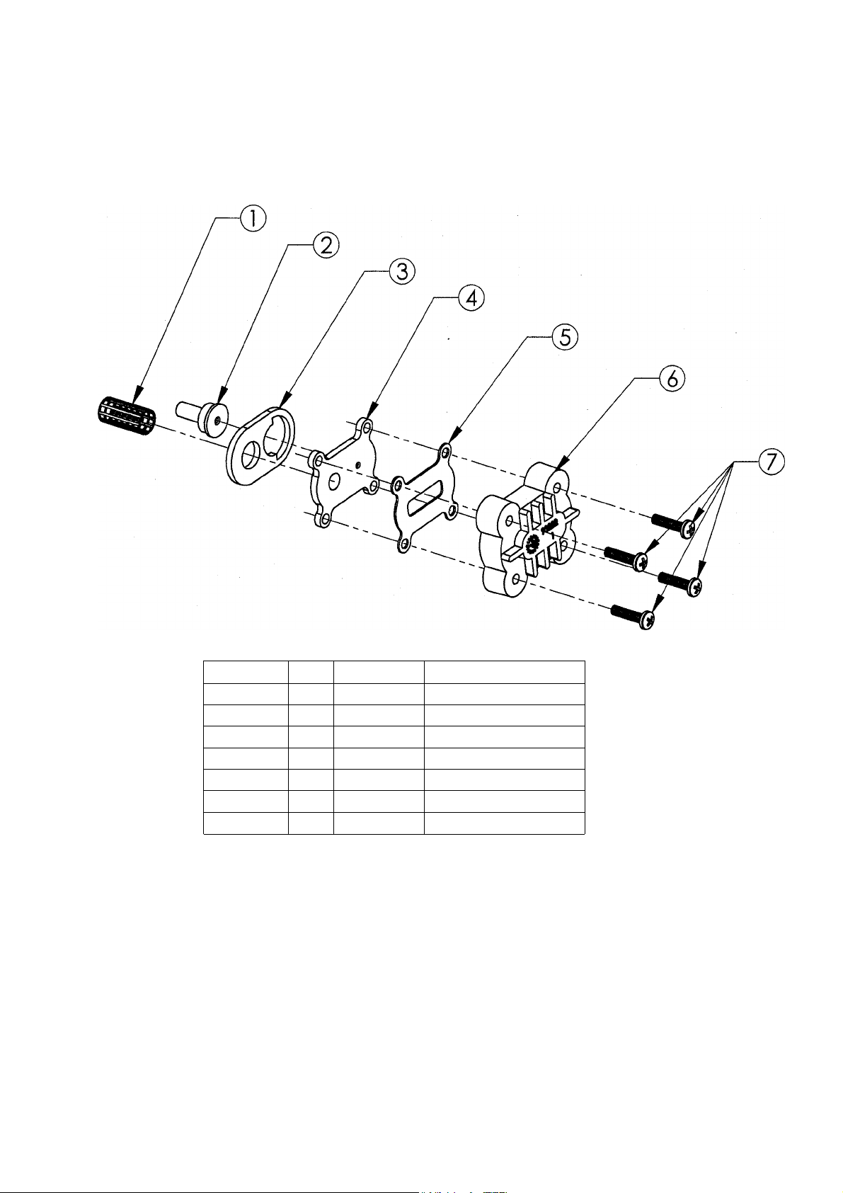
Parts —
Figure 6-Injector Assembly
ITEM NO.
1 1
2
3
4
5
6
7
QTY. PART NO.
93810
1
1
1
1
1
4
93223
93220
93221
93232
93222
90807 Screw
DESCRIPTION
Injector Screen
Injector Throat
Injector Seal (Thick)
Injector Nozzle
Top Injector Seal (Thin)
Injector Cap
23
Page 24

Parts –
Injector Assembly
93223 Injector Throat:
that draws the brine solution from the brine cabinet. The center hole should be clear of debris,round
and undamaged. The Throat should be pressed flush into the opening in the valve. If the Throat is
removed, it must be replaced with a new one.
93220 Thick Injector Seal:
ket has a definite hole pattern that has to match-up with the Nozzle and Main Valve Body opening.
The gasket seals at its outer edges and between the inlet screen and nozzle opening. These areas
must be free of defects such as tears or pits and be free of debris.
93221 Injector Nozzle:
solution from the Brine Cabinet. There are two openings in the Nozzle plate. The small hole, flush
on both sides, is the one that creates the "injection-stream" that enters the Throat. It is very important that this hole is clear of debris, round and undamaged. If this hole becomes "clogged", do not
use anything such as metal objects to clear this opening . Damage may occur. Use a clean cloth
and flush with water. If necessary, a wood toothpick may be used.
the Nozzle hole should line up with the Throat.
93232 Thin Injector Seal:
be free of defects such as tears or cuts and be free of debris.
In conjunction with the Injector Nozzle, Part # 93221, it creates the vacuum
Seals between the Injector Nozzle and the Main Valve Body. The gas-
Together with the Throat, 93223, creates the vacuum that draws the brine
When assembling to the Valve,
Seals between the Injector Nozzle and Injector Cap. The gasket must
93222 Injector Cap:
Valve Body. The four machine screws should be tightened evenly and "snug".
93810 Injector Screen:
Throat. Attaches to the cylinder on the Nozzle plate and spherical "bump" inside the Valve Body.
Some compression of the screen may occur during assembly. The opening in the screen must be
clear to ensure proper flow to the Injector assembly.
Holds the injector assembly together and seals the assembly to the Main
Acts as pre-filter to keep debris from entering the Injector Nozzle and
24
Page 25
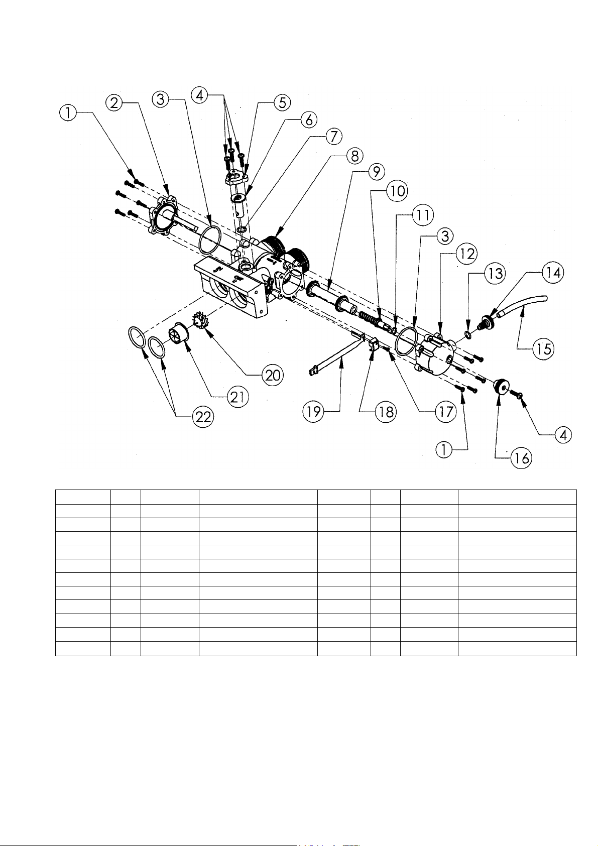
Parts
Figure 7 -Bypass Assembly
ITEM NO.
1
2
3
4
5
6
7
8
9
10
11
QTY.
12
1
2
6
1
1
1
1
1
1
1
PART NO. DESCRIPTION
90807 Screw
90262
93808
90802
90252
90222
90827
90246
90616
90218
90803
Bypass Endcap - left
0-Ring
Screw
Cap - Blending Dial
Blendind Dial
O-Ring
Bypass Housing
Bypass Piston Assembly
Bypass Piston Drive Shaft
0-Ring
25
ITEM NO.
12
13
14
15
16
17
18
19*
20 *
21 *
22
QTY. PART NO.
1
2
1
1
1
1
1
1
1
1
2
90263
90828
90226
90812
90221
90809
90232
93858
90522
93229
93838
*
Not available on WaterMax Filters
DESCRIPTION
Bypass Endcap - right
0-Ring
Test Port Valve
Tubing 4.0"
Bypass Piston Knob
Screw
Turbine Sensor Cap
Turbin Sensor Assembly
Turbine Assembly
Flow Director
0-Ring
Page 26

Parts —
Bypass Assembly
90246 Bypass Housing:
"Hard Water" Blending Valve and Bypass Piston. The recommended seal for the 1 '/" male inlet-outlet threads
is the plastic Hook-up Nut (90251), 0-ring (90837), and Copper Adapter (90254). Make sure the 0-ring is
between the Housing and Copper Adapter. The 0-ring seal areas at the Main Valve Body inlet and outlet must
be smooth and free of defects and debris, and lubricated with silicone grease before assembling.
ing to the Main Valve Body, put the 0-rings on the male bosses on the Valve Body and push the Bypass into
place; if not, the 0-rings may be "pinched". If the 0-rings are pinched, replace with new ones. The Bypass is
pre-assembled with the Sensor housing and turbine axle. These are not field serviceable and if damaged, must
be replaced with a new assembly. The Bypass Piston bore is to be smooth and, at the recessed areas, have a
smooth transition (no sharp corners) to the seat areas.
90262 Bypass End Cap -
with an 0-ring used as an axial or "face" seal. The 0-ring sits in a groove in the End Cap. This groove must be
free of defects such as pits or scratches and also free of debris.
care should be taken to make sure that the 0-ring stays in the groove in the End Cap. If misaligned, the 0-ring
can become pinched and leak. Also, on the End Cap is the Piston Axle, a '/" square shaft that acts as a guide /
slide and anti-turning mechanism for the Bypass Piston.
90263 Bypass End Cap -
with an 0-ring used as an axial or "face" seal. The 0-ring sits in a groove in the End Cap. This groove must be
free of defects such as pits or scratches and also free of debris.
care should be taken to make sure that the 0-ring stays in the groove in the End Cap. If misaligned, the 0-ring
can become pinched and leak. Also, on the End Cap is the guide / bushing for the Bypass Piston Drive Shaft.
There is an 0-ring seal at the opening for the Drive Shaft. This seal area must be free of defects such as pits or
scratches and also free of debris.
90218 Bypass Piston Drive Shaft: The Drive Shaft has an acme thread which is used to move the Piston from
"bypass" to "service" position.
essary to turn the Handle (90221) until the Piston (90616) stops. Additional pressure (torque) will not improve
the seal. As a matter-of-fact, once the Piston reaches the stop at either position, it can be backed off up to one
half turn of the handle and still achieve a seal.
90616 Bypass Piston Assembly:
indentations and cuts. The Piston should move freely into and out of the Bypass Housing without damaging the
Hydro-slides. If the Hydro-slides catch, tear or crimp, the Housing should be replaced. Note: Some compres-
sion
will
occur when the Hydro-slides pass through the seal areas.
93858 Turbine Sensor Assembly:
The three wire assembly connecting the "black wafer" Hall Effect Sensor to the Controller board must not be
severely bent (folded over,) cut, or broken. Care should be taken when putting the Sensor into the Sensor
Housing. The "spring" flap below the Sensor must be gently bent over (on top of) the Sensor, and then the
Sensor slides all the way into the Sensor Housing. The round hole of the Sensor mounting tab is then placed
down over the mounting screw boss. The cap is then put in place and the mounting screw is installed. A slot is
provided in the cap for the wire way to exit. The three-wire socket connector must be properly installed in the
controller.
the stops.
90522 Turbine Assembly:
cent to the axle opening.
cants. If the Turbine should become "jammed", clean and flush the Turbine and Bypass Valve.
90252 Blending Dial Cap:
tation.
90222 Blending Valve:
when pointing toward the Main Valve Body and open when pointing toward the inlet side.
90226 Test Port Valve:
The Bypass must be in the "service" position to get an accurate sample. There are two types of seals on the
Test Port.
a compression seal between the Test Port Valve material and the Right End Cap material. If this seal is "over-
tightened", it can damage the sealing area on the End Cap causing a permanent leak.
Stops on the connector prevent improper (upside down) assembly. Do not force the connector past
One seal is an 0-ring which seals off the threaded area when the Valve is opened. The other seal is
Makes the connection between the plumbing and Main Valve Body. Also, contains the
When attach-
Seals the left Piston opening on the Housing (90246). The opening is sealed
Left:
When assembling the End Cap to the Housing,
Right:
When assembled to the axle, the Turbine should spin freely. Do not use any lubri-
The dial permits the addition of "hard water" into the soft water outlet. It is closed
The Test Port Valve is used to draw water samples for testing of treated water. Note:
Seals the right Piston opening on the Housing (90246). The opening is sealed
When assembling the End Cap to the Housing,
When operating the Bypass, to achieve either "service" or "bypass", it is only nec-
The white Teflon Hydro-slide 0-ring covers should be free of defects such as
Picks up the magnetic field from the Turbine and relays it to the Controller.
The turbine must have a 1/8" diameter Rare Earth magnet pressed into place adja-
%2"
The Cap should be held in place by the three
screws and be in the proper orien-
26
Page 27
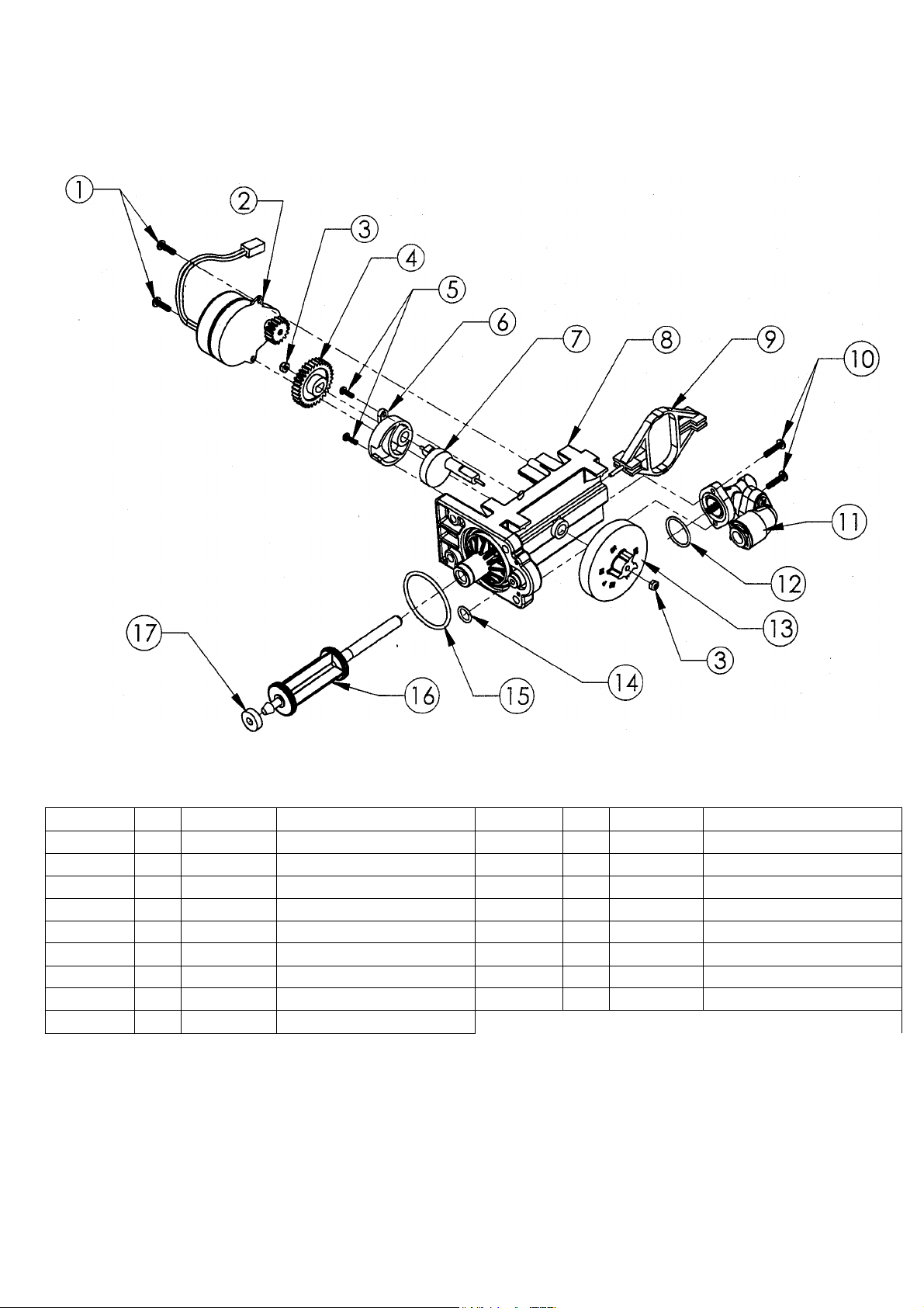
Parts —
Figure 8-Drive End Cap Assembly
ITEM NO.
1
2
3
4
5
6
7
8
9
QTY.
2
1
2
1
2
1
1
1
1
PART
NO.
90802 Screw
90217
93891
93238
90809 Screw
93219
93217
93583
93216
DESCRIPTION
Drive Motor
1/4" Hex Nut
Drive Gear
Piston Slide Cam Cover
Piston Slide Cam
Drive End Cap
Piston Slide
ITEM NO.
27
10
11
12
13
14
15
16
17
QTY.
2
1
1
1
1
1
1
1
PART
NO.
90818 Screw
93601-JG
90821
54502
90828
93808
95522-A
93839
DESCRIPTION
Brine Valve Housinq Assembly
0-Ring
Magnet Disk Assembly
0-Ring
0-Ring
Drive Piston Assembly
Drain Gasket
Page 28

Parts –
Drive End Cap Assembly
93583 Drive End Cap:
opening is sealed with an 0-ring used as an axial or "face" seal. The 0-ring sits in a groove in the
End Cap. This groove must be free of defects such as pits or scratches and also free of debris.
The smaller diameter seal is accomplished with an 0-ring used as a radial seal. The 0-ring should
be placed on the male boss on the End Cap. When assembling the End Cap to the Valve Body,
care should be taken to make sure the small 0-ring is aligned with the opening in the Valve Body
and that the large 0-ring stays in the groove in the End Cap. If misaligned, the 0-rings can
become pinched and leak.
90217 Drive Motor:
The brass pinion gear on the Motor should engage the plastic Drive Gear. The wires should be
securely fastened to the Controller.
93216 Piston Slide:
steel threaded stud should be pointing toward the Valve Body.
93217 Piston Slide Cam:
steel shaft that runs through the main drive axle. The Drive Gear is attached at the short end and
the Magnet Disc at the other end. The Slide Cam is assembled inside of the Piston Slide (93216).
This Cam Shaft should turn freely before the Motor is assembled.
Seals the two openings on the Main Valve Body. The larger diameter
1/2"
The Motor is held in place by two
The Slide should move freely inside the End Cap Housing. The stainless
This is the "heart" of the drive system. There is a threaded stainless
screws. The screws should be "snug".
93219 Piston Slide Cam Cover:
acts as a bushing for the Cam Shaft.
93238 Drive Gear:
which transfers the "torque" generated by the Motor to the rest of the drive system. If the drive
system becomes jammed, this opening can become "rounded" causing the gear to turn, but not the
Piston Slide Cam. If this occurs, clear the jam and replace the Drive Gear and Piston Slide Cam
(93217).
93601-JG Brine Valve Assembly:
screws and has one 0-ring seal. When assembling, the 0-ring should be placed on the Drive End
Cap boss and be lubricated with silicone grease. A twisting action should be applied along with
pressure until the 0-ring seats.
The Olive gear is assembled to the Slide Cam by means of a "keyed" opening
The cover secures the Piston Slide Cam (93217) in place and
3
Attaches to the Drive End Cap with two
/" thread cutting
28
Page 29
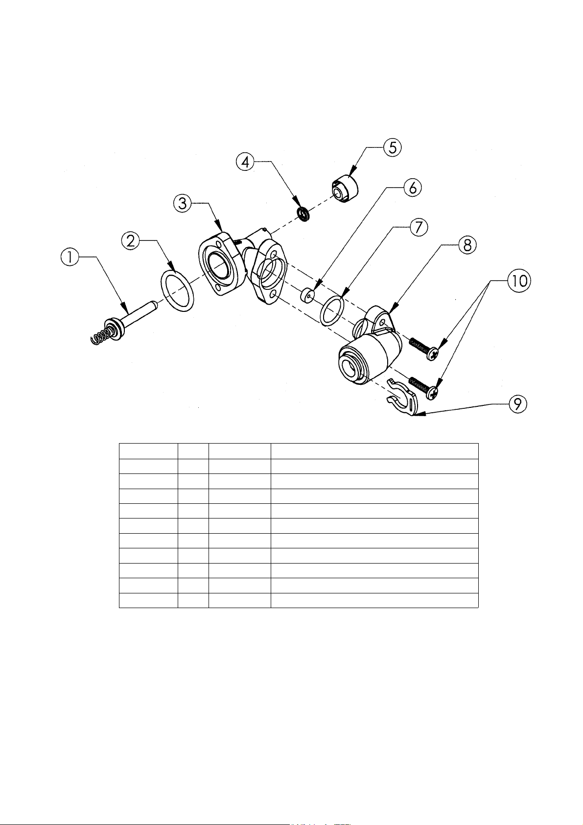
Parts —
Figure 9 - Brine Valve Housing Assembly
ITEM NO.
1 1
2
3
4
5
6
7
8
9
10
QTY.
1
1
1
1
1
1
1
1
2
PART NO.
93620
90821
93260
93878
93254
90843
93805
93243-JG
200199
90818 Screw
DESCRIPTION
Piston Assembly (includes 0-ring & Spring)
0-Ring
Housing
Quad Ring
Quad Ring Retainer
.5 gpm Flow Control
0-Ring
Housing Cap Assembly (John Guest)
3/8" Locking Clip
29
Page 30

Parts –
Brine Valve Housing Assembly
93260 Housing:
place by the quad ring retainer (5). The brine valve housing has four retaining lugs that secure
the quad ring retainer. Just inside the entrance hole for the Brine Piston (1) is a concave seat
area that must be free of defects such as nicks, indentations or debris. If any defects are
detected by visual inspection, repair or replace as needed.
To replace the Quad-ring, it will be necessary to remove the brine valve housing assembly
from the drive end cap (after by-passing and depressurizing the conditioning appliance). Push
the piston assembly (1) out of the housing. To remove the quad ring retainer (5) push in and
turn "clockwise" to unlock the retainer. CAUTION! Do not attempt to remove the retainer with
the piston assembly in place. This will damage the housing and/or the retainer. Push the piston
back into the housing to dislodge the old quad-ring (4) and discard it. Remove the piston, insert
the new Quad-ring and lock the retainer onto the housing by pushing in and turning "counter-
clockwise" to secure the Quad-ring. Replace the piston assembly and attach the brine valve
assembly to the drive end cap and restore service to the conditioning appliance.
93243-JG Housing Cap:
Housing flange. An 0-ring seals the Cap and Housing. Place the 0-ring into the housing opening, lubricate with silicone grease and then using a twisting action, pressure insert the Cap.
CAUTION: The 3/8" locking ring (8) must be installed to prevent air from being drawn into the
appliance during brine rinse.
Should have a Quad-ring for the Piston seal. The Quad-ring (4) is held in
The Cap is held in place by two 5/8" machine screws that engage the
90843 .5 gpm Flow Control:
"flat"; the other is "concave". The button should be centered in the housing opening with the
four locator "ribs" with the concave side facing the Housing Cap.
93620 Brine Piston:
spring pressed onto a boss on the other side. The 0-ring should be free of defects such as cuts
or debris on the shaft side. The Piston is Teflon coated brass and should be free of scratches.
The Piston should move freely in the housing; silicone lubrication is not recommended on the
Piston shaft.
The Piston should have an 0-ring on the shaft side of the flange and a
The Flow Button has two distinct and different sides. One is
30
Page 31
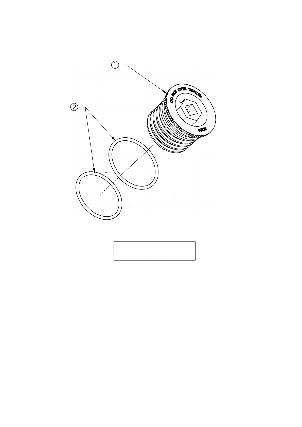
Parts —
Figure 10 - Fill Plug Assembly
(1)
90238 Fill Plug:
ITEM NO.
The Fill Plug seals the media access ports in the Media Tank. Care
QTY.
1 1
2 2
PART NO.
90238
90819
DESCRIPTION
Fill
Plug
0-Ring
should be taken that the 0-ring seal areas are kept clean and free of debris. Also, both 0-
rings should be in the proper locations, one under the flange and one in the groove. Do not
overtighten the Fill Plug when assembling.
3
Media Tank, stop tightening. A
(2)
90819 Fill Plug 0-ring
(3)
90618 Fill Plug Assembly
/" socket is recommended for assembly.
(contains all of the above parts)
When the flange comes into contact with the
31
Page 32
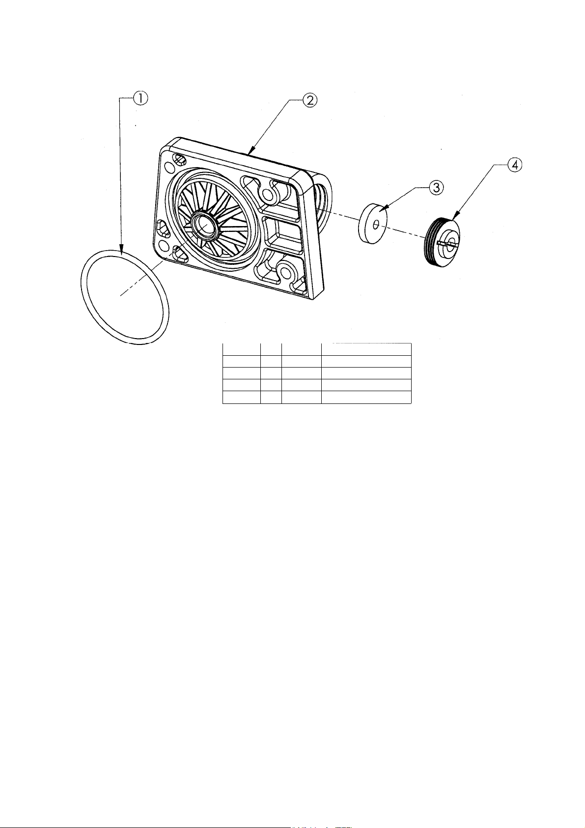
Parts -
Figure 11 - Drain End Cap Assembly
90268 Drain End Cap:
(1)
ITEM NO.
QTY. PART NO.
1
2
3
4
1
1
1
1
93808
90268
H2086-3.0
90267
Seals the left opening on the Main Valve Body. The opening is sealed with
DESCRIPTION
O-Rinq
Drain End Cap
Drain Line Flow Control
Retainer
an 0-ring used as axial or "face" seal. The 0-ring sits in a groove in the End Cap. This groove must be
free of defects such as pits or scratches and also free of debris.
When assembling the End Cap to the
Valve Body, care should be taken to make sure that the 0-ring stays in the groove in the End Cap. If
misaligned, the 0-ring can become pinched and leak.
H2086 Drain Line Flow Control Button:
(2)
constant
or minus 10%) backwash flow rate at varying pressures. Care should be taken when
(plus
The Drain Line Flow Control Button (D.L.F.C.) maintains a
replacing FCB's to insure that the correct rate is being used for a particular model. Refer to Engineering
Specifications, pg. 13. The flow control button should be assembled with the lettering facing the retainer.
H2086 - 2.4*
H2086 - 3.0*
H2086 - 5.0*
H2086 - 7.0*
90267 Retainer:
(3)
The Retainer holds the backwash Flow Control Button in place. One side is
smooth and the other has a groove for a screw driver. When assembling the retainer to the Drain End
Cap, the retainer should be "screwed" in until it stops. If the retainer is not fully engaged, the Flow
Control may not function properly.
93808 End Cap 0-ring
(4)
90614 Drain End Cap Assembly
*The numbers shown after the Drain Line Flow Control Button Part # indicate the back wash flow rate in gpm.
(contains all of the above items)
32
Page 33
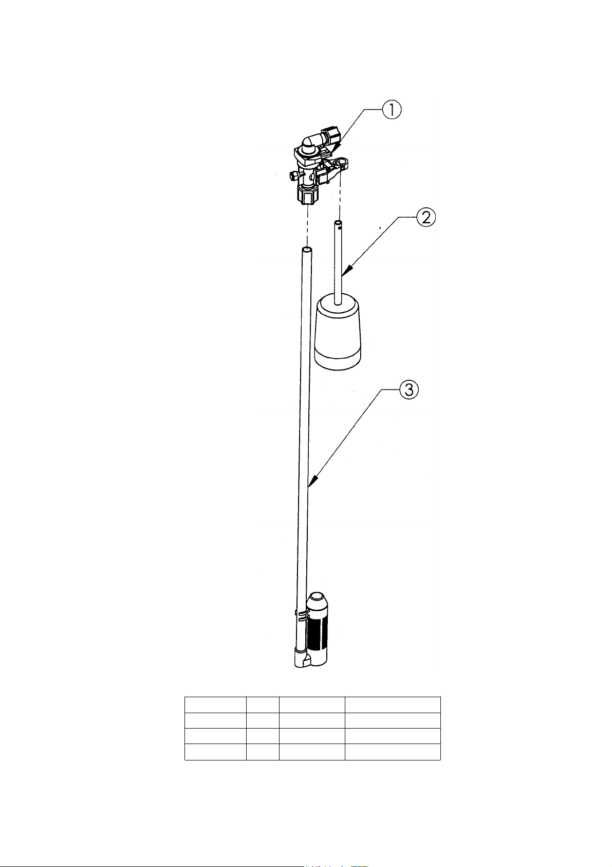
Parts -
Figure 12 - Safety Shutoff
ITEM NO.
1 1
2
3
QTY.
1
1
PART NO.
54226
54227
54225
33
DESCRIPTION
Safety Shutoff
Float
Air Check
Page 34
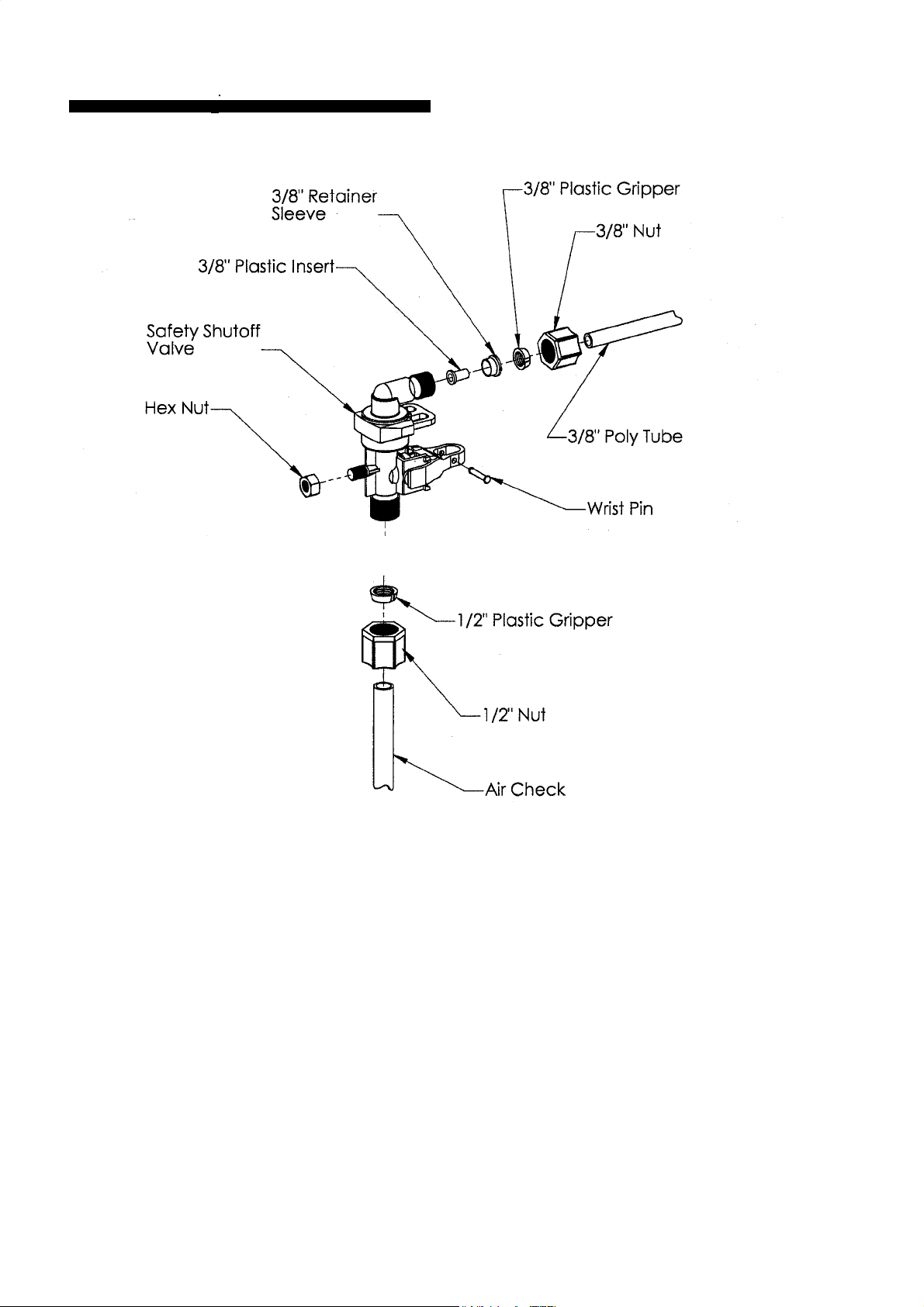
Parts —
0
Figure 13 - Brine Valve Elbow Installation
.
a
3/8" Plastic Gripper
1 /2" Retainer
Sleeve
The nut, gripper and retainer sleeve are
a 3 piece assembly that can come apart
if removed from the elbow body. Parts
must be re-assembled exactly as shown
to function properly.
When connecting the 3/8" polytube, it is
first necessary to assemble the nut,
gripper and retainer sleeve on the tubing before inserting the plastic insert.
Screw the nut on the elbow body. With
a wrench tighten nut securely to create
a pressure tight connection.
34
Page 35

25 Year Limited Warranty
TO PLACE THIS EQUIPMENT UNDER WARRANTY, THE
WARRANTY REGISTRATION CARD MUST BE COMPLET-
ED AND RETURNED BY THE ORIGINAL OWNER TO
HAGUE QUALITY WATER INTERNATIONAL WITHIN 30
DAYS OF INSTALLATION.
Coverage
This warranty covers the Hague WaterMax® System delivered to the oringal owner when the system is purchased for
personal, family, or household use. It is intended to cover
defects occurring in workmanship or materials or both.
Warrantor's Performance and Length of Warranty
Hague Quality Water International warrants that upon receipt
from the owner of any Hague Media Tank, Brine Tank, Valve
Body, or the fine mesh polystyrene resin found to be defec-
tive in material or workmanship, Hague will repair or replace
the defective item, at no charge for that item, for 25 YEARS
from date of installation.
Hague Quality Water International further warrants that upon
receipt from the owner of any other mechanical or electronic
parts, which are found to be defective in material or workmanship, Hague will repair or replace the defective parts, at
no charge for those parts for 3 YEARS from date of installa-
tion; and therafter will repair or replace the defective parts
only upon receipt of payment by the owner of the defective
parts only upon receipt of payment by the owner of the following percentages of the then current list prices for the
parts:
If
more than 3 years from
date of installation but not
more than 4 years
50%
If
more than 4 years from
date of installation but not
more than 5 years
55%
If
more than 7 years from
date of installation but not
more than 8 years
70%
If
more than 8 years from
date of installation but not
more than 9 years
75%
will not be liable for, nor will it pay service call or labor charges
incurred or expended with respect to this warranty.
In the event the water supply being processed through this
product contains bacterial iron, algae, sulfur, tannins, organic
matter, or other unusual substances, then unless the system is
represented as being capable of handling these substances in
the system specifications, other special treatment of the water
supply must be used to remove these substances before they
enter this product. Otherwise, Hague Quality Water
International shall have no obligations under this warranty.
This warranty does not cover damage to a part or parts of the
system from causes such as fire, accidents, freezing, or unreasonable use, abuse, or neglect by the owner.
This warranty does not cover damage to a part or parts of the
system resulting from improper installation. All plumbing and
electrical connections should be made in accordance with all
local codes and the installation instructions provided with the
system. The warranty does not cover damage resulting from
use with inadequate or defective plumbing; inadequate or
defective water supply or pressure; inadequate or defective
house wiring; improper voltage, electrical service, or electrical
connections; or violation of applicable building, plumbing, or
electrical codes, laws, ordinances, or regulations.
THIS WARRANTY DOES NOT COVER INCIDENTAL, CONSEQUENTIAL OR SECONDARY DAMAGES.
ANY IMPLIED WARRANTIES ON THE PRODUCT
DESCRIBED IN THIS WARRANTY WILL NOT BE EFFEC-
TIVE AFTER THE EXPIRATION OF THIS WARRANTY.
Some states do not allow limitations on how long an implied
warranty lasts or the exclusion or limitation of incidental or
consequential damages, so the above limitations and exclu-
sion may not apply to you. This warranty gives you specific
legal rights and you may also have other rights which vary
from state to state.
If
more than 5 years from
date of installation but not
more than 6 years more than 10 years
60% 80%
If
more than 6 years from
date of installation but not
more than 7 years
65%
All defective parts must be returned, along with the equipment serial number and date of original installation, to an
authorized Hague dealer of Hague Quality Water
International PREPAID, and replacement parts will be
returned by Hague to the owner FREIGHT COLLECT.
Further Exclusions and Limitations on Warranty:
This warranty is null and void unless the Hague System
was purchased from an independent Hague dealer.
THERE ARE NO WARRANTIES OTHER THAN THOSE
DESCRIBED IN THIS WARRANTY INSTRUMENT.
This warranty does not cover any service call or labor costs
incurred with respect to the removal and replacement of any
defective part or parts. Hague Quality Water International
If
more than 9 years from
date of installation but not
If
more than 10 years from
date of installation
100%
Claims Procedure
Any defects covered by this waranty should be promptly
reported to Hague Quality Water International at 4343 South
Hamilton Road, Groveport, Ohio 43125. In writing about the
defects, please provide the original owner's name, telephone
number, and original address; serial number and model number of the product; date of purchase; and name of dealer from
whom purchased. Hague Quality Water International reserves
the right to replace defective parts with exact duplicates or
their equivalent.
For Owner's Reference
Model No.
Installation Date Installer's Signature
Independent Dealer
Equipment Serial No.
35
Page 36

Brine Cabinet Data
Based on the water level measured from the bottom of the WATERMAX brine cabinet WITH GRID
PLATE, the following depths correlate to the amount of salt used per regeneration:
DEPTH
(inches)
6 .74
7
8 2.2
9
10
11
12
13
14
15
16
17
18 9.6
19
20
21 11.8
22
23
24
SALT
(lbs.)
1.5
3.0
3.7
4.4
5.2
5.9
6.6
7.4
8.1
8.8
10.3
11.0
12.5
13.3
14.4
PLEASE STUDY THE ABOVE CHART TO CONFIRM THIS INFORMATION.
WaterMax Brine Cabinet Statistics
No Salt
1"
= .791 gallons
1"
= 2.2148 lbs. Salt
1 lb. = .451" water level
With Salt
1"
= .264 gallons
1"
= .738 lbs. Salt
1 lb. = 1.353" water level
36
 Loading...