

Page 1

KE-USBMX20
Matrix Keypad Interface
User Manual
Page 2

Table of Contents
Introduction to the KE-USBMX20 1
Computer Connection 2
Interfacing to the KE-USBMX20 Header 3
Status Feedback LED 4
The KE-USBMX20.EXE Program 4
The Program Screen 5
File Menu Selections 7
Sample KE-USBMX20 Confi guration 9
KE-USBMX20 Confi guration with FN key 16
Error Messages 20
KE-USBMX20 Operating Tips 22
Appendix A: Specifi cations 23
Appendix B: Command Line Loader 24
Accessories 24
Thank you for purchasing the
HAGSTROM ELECTRONICS, INC.
KE-USBMX20. This product is confi gurable in a variety
of ways to meet your specifi c requirements. Please
take a few minutes to read this manual before using
your KE-USBMX20.
HAGSTROM ELECTRONICS, INC. warrants this
product against defects in material or workmanship for a
period of ONE YEAR from the original purchase date. We will
repair or replace (at our option) the returned defective unit
at no charge during this warranty period.
No responsibility is assumed for any special, incidental,
or consequential damage resulting from the use of or
inability to use this product. In no case is
ELECTRONICS, INC. to be liable for any amount which
exceeds the purchase price of the unit, regardless of the
claim.
No other warranty, written or verbal, is authorized. This
warranty is applicable only to units sold in the United States.
Units sold outside the United States are covered by a similar
warranty.
Depending on the state in which you live, you may have additional rights.
Great care has been taken during the assembly, testing, and burn-
in of your KE-USBMX20 to ensure its performance. If you have any
questions, please send us an email or give us a call. Support is
available Monday through Friday, 8:00 am to 5:00 pm (EST).
customer service email: sales@hagstromelectronics.com
Call Toll Free 888-690-9080, or (540) 465-4677
Page 3

1
Introduction to the KE-USBMX20
Our KE-USBMX20 Keyboard Encoder is a product designed to interface
Matrix Keypads, Membrane Switches, and/or other contact closures
to the computer’s USB port. Devices connected to the KE-USBMX20
Input header produce keystrokes that appear to the PC as if they were
entered from a standard USB keyboard. The KE-USBMX20 can scan
any matrix up to a 5 x 4 arrangement.
The KE-USBMX20 is programmable by the user. This programmability
feature allows the configuration of the matrix row and column pins as
well as the selection of the keystrokes that will be sent to the PC for
each matrix position. The user’s configuration is stored in non-volatile
memory so that the information is retained on the unit even after
power is turned off. Responses to each key can be programmed as a
single keystroke or a macro sequence of keystrokes.
The KE-USBMX20 Input Header
The 9 pin header provides 9 signals that can be programmed to scan
any size matrix up to 5 x 4. Any of the Input pins may be designated as
either a Column or a Row. The KE-USBMX20 configures its scanning to
the keypad, allowing the direct 1:1 connection to the header of many
“off the shelf” keypads without any cabling.
Power Requirements and Hardware
The KE-USBMX20 requires no external power source. It is powered
directly from the USB port on the PC. One micro-B to A Type USB cable
is provided with the unit.
Supported Devices
All devices with a standard USB port will work with the KE-USBMX20.
The KE-USBMX20.EXE configuration program is for Windows based
systems, but once programmed, the KE-USBMX20 may be moved to
another platform that supports a standard USB keyboard.
Default Settings
The KE-USBMX20 is programmed and shipped with a default 5x4
matrix configuration. This default configuration can be changed or
modified at any time by the user with the KE-USBMX20.exe program.
Page 4
Operating Voltage
Operating Current
Operating Temp.
PC Interface
Input Debounce Time
KE-USBMX20 Header
Mating Header
(on keypad)
ESD Input Protection
Max Switch Resistance
.80”
Computer Connection
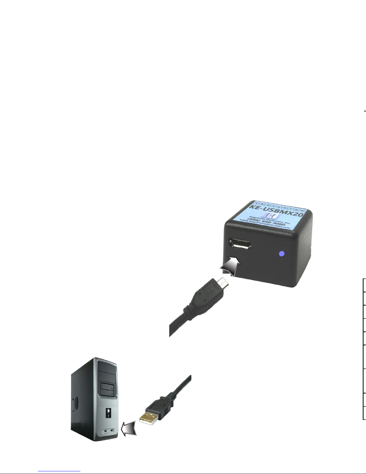
There is a micro B type USB connector located on the side of the
KE-USBMX20. Connection to this port can be made with power
on as the KE-USBMX20 supports “Hot Plug” operation as a USB
device as well as a boot keyboard device.
Plug the USB Micro Type B side of the USB cable to the KEUSBMX20 port. Plug the Type A side of the USB cable to the
computer’s USB port or to a USB Hub port.
Up to four KE-USBMX20 units may be used on the same computer
and programmed through the supplied load program.
Micro Type B to KE-USBMX20
Type A USB to KE-USBMX20
Page 5
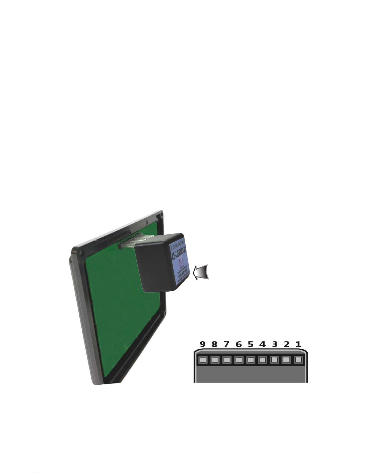
Interfacing to the KE-USBMX20 Header
The header on the KE-USBMX20 consists of 9 configurable pins.
The pins are designated as “1” through “9”.
Use the supplied KE-USBMX20.EXE program to configure the
header pins as either Rows or Columns. Keystrokes are initiated
by shorting a Row pin to a Column pin through a contact closure.
The pins that are defined as Columns will sink current while
scanning the matrix. The Rows are used to read the status of
the inputs when a Column is active.
Keypads with male headers can be directly plugged onto the KEUSBMX20 connector. KE-USBMX20 pins can be configured to
be either Rows or Columns to allow for this direct attachment.
*Note: Keypads with male pins may be connected directly. For
membrane keypads with female headers, adapters may be used
to directly connect from the pigtail to the KE-USBMX20 header.
(See Accessories on page 20)
322
View of the 9 pin female
header pin designations as
seen from the bottom of the
KE-USBMX20
The KE-USBMX20 header
connects directly to the
keypad header. Secure with
the adhesive pad included
or with your own fastening
system.
Page 6

“Error saving file”
This error message is shown if the KE-USBMX20.EXE program
attempts to save a file that is already open in another application,
or if there is not enough disk space. If this happens, close the
other application and try saving the file again.
“Error: Pin * is used for multiple scan lines”
If a header pin is used to designate more than one row or
column or is used for both a row and a column, this error will
be displayed when saving the configuration to a file or to the
KE-USBMX20. Check the matrix configuration and eliminate
redudant pin letters. The error message will give the letter of the
duplicate pin.
(Example: “Error: Pin 5 is used for multiple scan lines”)
The KE-USBMX20.EXE Program
The KE-USBMX20 unit is shipped with a CD ROM containing the
KE-USBMX20.EXE utility program which is used for configuring
the unit. Configuration parameters include the defining of the
pins used as Rows and Columns, and the keystroke or keystrokes
generated by the activation of a key within the matrix.
Getting Started
To begin using the KE-USBMX20, follow the steps listed below.
1. Attach the KE-USBMX20 to the computer as described
on page 2 under the section “Computer Connections”.
2. Insert the CD and save the contents to its own folder
on the hard drive. The CD may now be removed and
stored in a safe location for future use.
3. Open the folder that was created in step 2 and start
the configuration program by selecting the program
file KE-USBMX20.EXE.
*Note: The programs must be copied to and run from its own
folder on the PC’s hard drive. The CD itself should be reserved
for back up purposes only.
4
Status Feedback LED
The KE-USBMX20 features a status LED on the side for user
feedback. When this light is Red, the unit has power but has not
been initialized by the system. Once initialized and scanning, the
LED will be Blue. When a key is detected as active, the LED will
light Green momentarily.
Status LED
Page 7
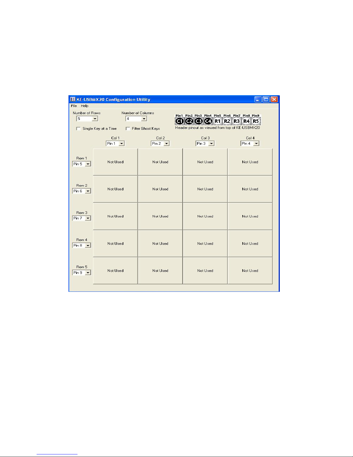
The Program Screen
The main program screen displays the configuration settings for
the KE-USBMX20. A list of these settings and a description of
how they pertain to the KE-USBMX20 setup are listed below.
*Note: The number of Rows plus the number of Columns
cannot exceed the total number of 9 pins. For example, 5 Rows
+ 4 Columns = 9 pins.
Number of Rows: The number of Rows are selected from
the drop down list. This may be any value from 1 to 8.
Number of Columns: The number of Columns are selected
from the drop down list. This may be any value from 1 to 8.
Row/Column Pins: The current row and column definitions
are shown in the upper right how they are being used on the
header. The view is looking down from the top of the KEUSBMX20 box.
5
Page 8
Column Pin Assignments: Column pin assignments are
selected from the corresponding drop down list across the top
of the matrix. Each column must have a header pin assigned to
it. Specify any pin “1” through “9” as a column.
Row Pin Assignments: Row pin assignments are selected
from the corresponding drop down list. Each row must have a
pin assigned to it. Specify any pin “1” through “9” as a row.
*Note: A pin cannot be assigned to both a Column and a Row.
If a conflict is detected during the matrix definition, it is indicated
in the header row/column assignment image in the upper right at
the pin position(s) being used for multiple definitions.
Single Key at a Time: This option will lock out additional
key activations once a key has been detected. No new key
responses will be generated until all keys have been released if
this option is checked in the configuration.
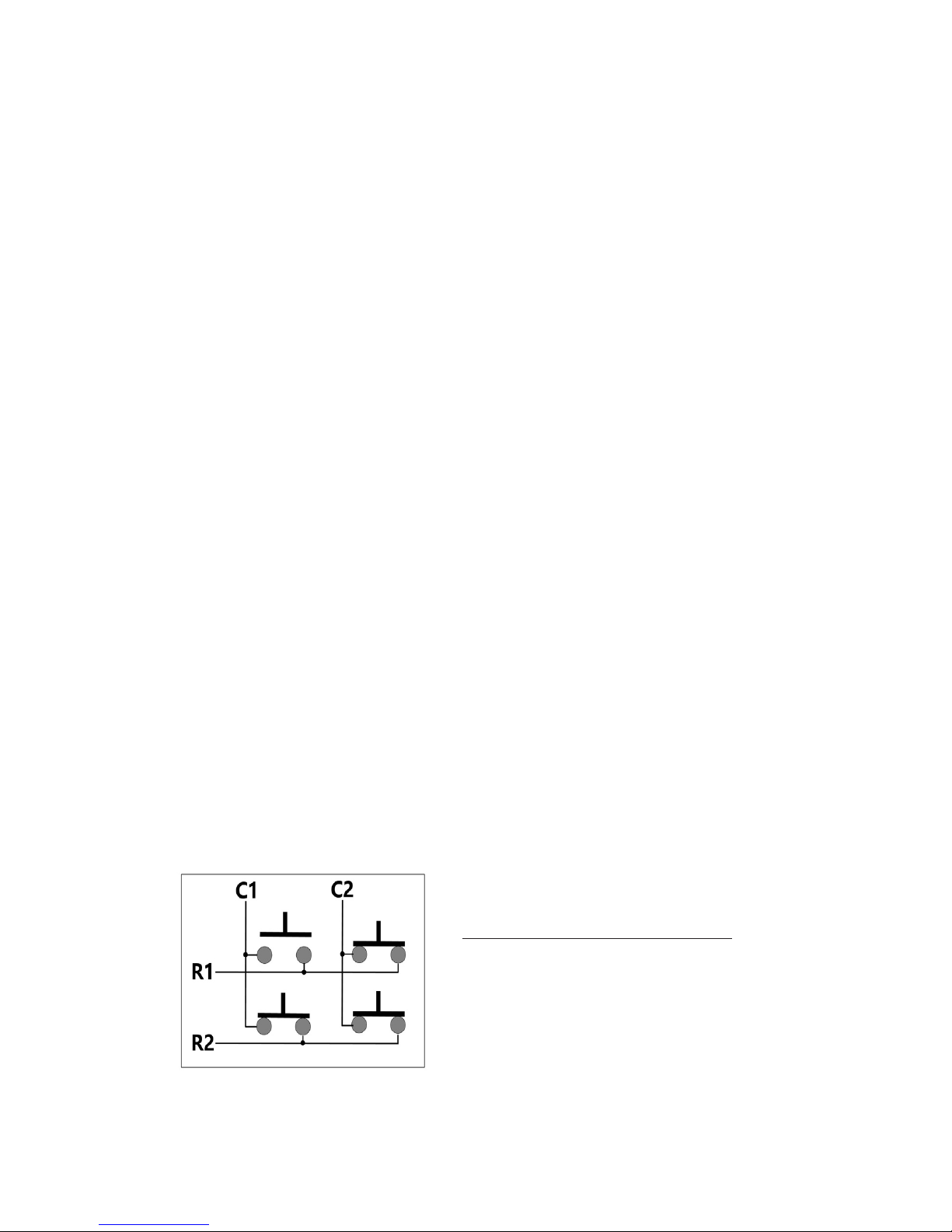
Filter Ghost Keys: Select this option to have the KEUSBMX20 filter out “ghost” conditions within the matrix.
Virtually any matrix has the potential for a “ghost” condition.
This condition occurs when 3 or more keys are active at the
same time and share a row and multiple columns, or a column
and multiple rows. The simple way to explain this condition is
to look at a 2 column by 2 row matrix. When 3 of any of the
keys are held, the result is that all 4 switches appear electrically
activated due to feedback of columns through the rows.
2 Column by 2 Row Matrix
When 3 switches pressed, all
4 electrically appear to be on.
If uncertain of this option, it is recommended that it be
selected.
6
The above matrix shows the keystrokes sent when keys are pressed and the
FN key is not active.
(Hold the right mouse button down while left clicking the FN key to toggle between the two matrix tables)
The matrix below shows the keystrokes sent in the same matrix when the FN
key is held active.
Page 9
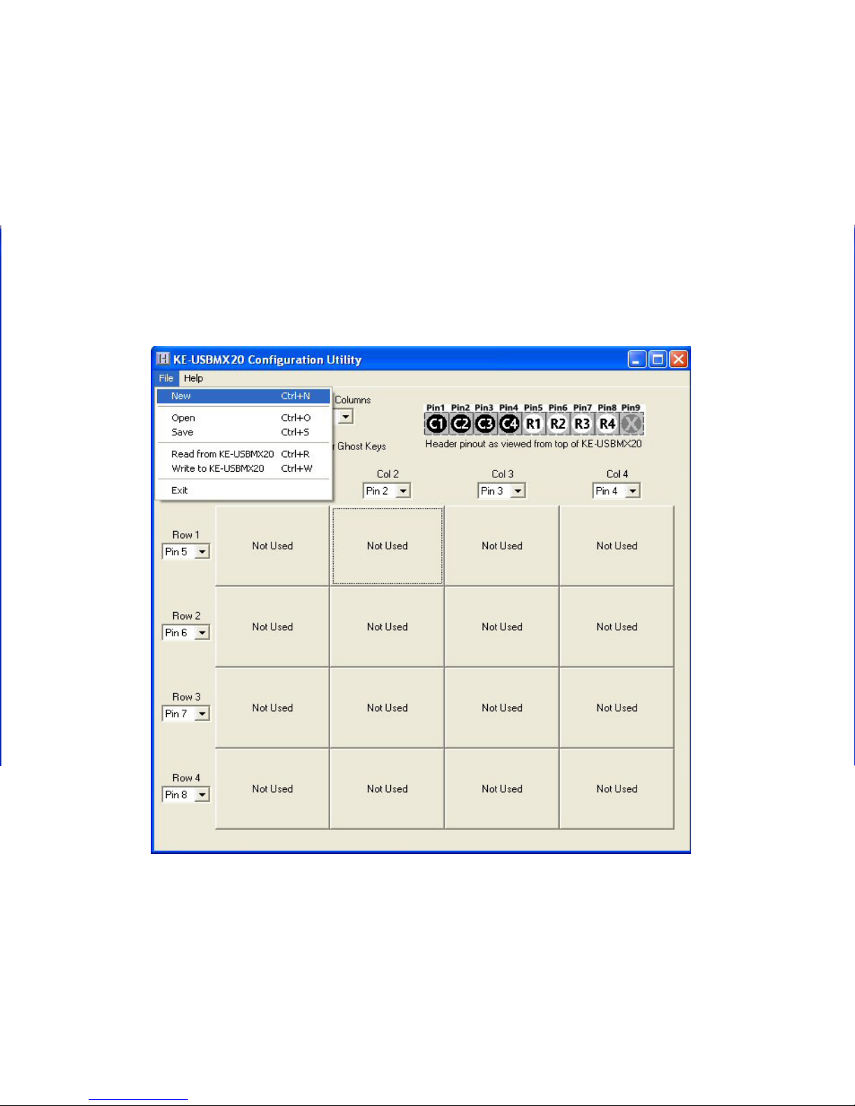
File Menu Selections
These selections are accessed by clicking on “File” in the upper
left corner of the main program screen. This list provides several
options that include creating and saving file configurations
as well as reading and writing the configuration to the KEUSBMX20. A list of these options along with descriptions of how
they pertain to the KE-USBMX20 setup are listed below. When a
configuration is created on the screen, it must be written to the
KE-USBMX20 to become active on the unit.
7
New: Creates a new configuration file by either clicking on
“New” with the mouse or by pressing Ctrl+N on the keyboard.
This option will also return the program screen to the default
settings.
Page 10

Open: Recall a previously saved configuration file by either
clicking on “Open” with the mouse or by pressing Ctrl+O on the
keyboard. Locate and select the name of the configuration file
on the PC that is to be opened.
Save: Once a configuration setup has been created on the
program screen, it is recommended that it be saved on the PC’s
hard disk. Click on “Save” with the mouse or press Ctrl+S on the
keyboard, then choose a location to save the file.
Read from KE-USBMX20: This option will read the
current configuration in the KE-USBMX20 and display it on the
screen. Click on “Read from KE-USBMX20” with the mouse or
press Ctrl+R on the keyboard to perform this operation. **
Write to KE-USBMX20: This option will write the current
configuration displayed on the screen to the KE-USBMX20.
The KE-USBMX20 can be programmed and re-programmed
as many times as necessary. Click on “Write to KE-USBMX20”
with the mouse or press Ctrl+W on the keyboard to perform this
operation. After the KE-USBMX20 has been loaded with the new
configuration, it will scan according to this new setup. **
** - Note that if multiple KE-USBMX20 units are detected, a
selection window will be displayed asking the user to select the
unit by it’s serial number. The 8 digit serial number is located
on the side label of the KE-USBMX20.
Exit: This option exits and closes the KE-USBMX20.EXE
program.
*Note: Make sure that the KE-USBMX20 is connected to the PC
before performing either the “Read to KE-USBMX20” or “Write to
KE-USBMX20” operations. If the KE-USBMX20 is not present, a
“The KE-USBMX20 was not Found” error will be displayed on the
computer screen.
The keystrokes shown for each key are the keys that will be sent
if the FN key is not active when those keys are activated.
To define the alternate keystrokes for each key that will be sent
when the FN key is held, put the cursor on the FN cell in the
matrix. While holding the right mouse button down, click the
left mouse button. This action will toggle between the key sets
that are sent with the FN held on and the FN key off.
Each matrix cell now shows “<FN ON>” to indicate that keys
defined in that position are the keys to be sent when the FN key
on the keypad is held.
When toggling between the FN key on table and the FN key off
table, the “<FN ON>” will appear only on the table with keystrokes
that will be sent when the FN key is held.
To define the keys for each of the positions on this screen, select
each cell and then the keystroke for each just as done previously
for the non-FN altered keystrokes.
Page 11

Sample KE-USBMX20 Configuration
916
The following exercise demonstrates how to program the KEUSBMX20 to scan a keypad. The keypad used in the example is
a 4 Column by 4 Row matrix (16 key) device.
This example uses the
keypad shown above.
The back of the keypad has eight pins. This
header plugs directly into the KE-USBMX20
connector. In this example, we align pin 1 of the
keypad header with pin 1 of the KE-USBMX20.
The included keying plug can be placed in to
pin 9 on the KE-USBMX20 to help with proper
header alignment.
The keypad matrix layout is shown in the figure above. Note
that the Row and Column signals are intermixed on the keypad.
The KE-USBMX20 can be configured to scan the keypad with it
plugged directly into the header with no added wiring.
Page 12

10
Step 2
After the matrix size has been assigned in step 1, the pins of the
KE-USBMX20 header to be used as rows and columns must be
defined.
On the keypad pins, the row and column assignments from the
keypad layout diagram are,
C1 = Pin 8, C2 = Pin 2, C3 = Pin 6, C4 = Pin 5
R1 = Pin 1, R2 = Pin 3, R3 = Pin 4, R4 = Pin 7
Step 1
Select the Number of Rows
on the screen and set it to
4.
Select the Number of
Columns, and set that value
to 4 as well.
The screen should appear
as shown to the right.
Step 5
Now that the setup is complete, it can be saved to disk. Specify
a file name under which to save the configuration.
Step 6
Load the KE-USBMX20 with the configuration. Be sure that the
KE-USBMX20 is connected to the PC. Once the KE-USBMX20 is
loaded, it will begin running the new configuration.
A delay function is provided within the macro sequences that
may be used to slow typing down to human speeds.
Page 13

Step 3
With the size of the matrix now defined, and the pins selected,
assign the keys to be emulated to each position in the matrix.
To assign keystrokes, click on the desired matrix position. A
diagram of the keyboard will be displayed, as shown below.
Click on the representation of the key to assign it to the matrix
position.
Note the repeat selection box at the bottom in the middle of the
key selection screen. If the key is to send only one keystroke
per activation, leave this box unselected. If the key is to repeat
when held active, select this box before choosing the key.
Page 14

12 13
Continue selecting each position in the matrix and assign the
desired key from the keyboard diagram for each position.
The repeat selection only applies to the current matrix key
position being defined. Repeated and non-repeated keys may
be intermixed within the same configuration.
In the example illustrations, the user clicked matrix position
Row 1, Col 4 and assigned the key “A” to it. The repeat box was
checked before selecting “A” from the key selection screen.
Step 4
The KE-USBMX20 has the capability of sending a macro, or
sequence of keystrokes for a single key activation. To program a
macro sequence, hold the Ctrl key before clicking on the matrix
cell to be defined. A macro sequence box will be displayed.
When defining a macro, each action is either the press (make) or
release (break) of a key. In this example, the desired character for the
key is “#”. In order to get this character, it must be entered the same
way as it would be manually typed on a keyboard.
The shift key will be “pressed” (“make”), then the “3” key is pressed.
At this point, both keys are being held down. In order to release them,
a “break” must be done for each key currently being held on. First
the “3” key is released, then the shift key. Before selecting a key, be
sure to check the “make” or “break” selection box above the keyboard
before the key, to achieve the desired press or release of the key.
When defining a macro, the key actions may be done when
the input is activated, “When Input Made”, or when the key is
released “When Input Breaks”, or at both events. Always be
sure to issue a “break” for any key in the macro sequence that
was activated with a “make”. Failure to release keys will result
in a stuck key, which can affect all further key actions.
Page 15

When defining a macro, each action is either the press (make) or
release (break) of a key. In this example, the desired character for the
key is “#”. In order to get this character, it must be entered the same
way as it would be manually typed on a keyboard.
The shift key will be “pressed” (“make”), then the “3” key is pressed.
At this point, both keys are being held down. In order to release them,
a “break” must be done for each key currently being held on. First
the “3” key is released, then the shift key. Before selecting a key, be
sure to check the “make” or “break” selection box above the keyboard
before the key, to achieve the desired press or release of the key.
When defining a macro, the key actions may be done when
the input is activated, “When Input Made”, or when the key is
released “When Input Breaks”, or at both events. Always be
sure to issue a “break” for any key in the macro sequence that
was activated with a “make”. Failure to release keys will result
in a stuck key, which can affect all further key actions.
Page 16

14 11
Step 3
With the size of the matrix now defined, and the pins selected,
assign the keys to be emulated to each position in the matrix.
To assign keystrokes, click on the desired matrix position. A
diagram of the keyboard will be displayed, as shown below.
Click on the representation of the key to assign it to the matrix
position.
Note the repeat selection box at the bottom in the middle of the
key selection screen. If the key is to send only one keystroke
per activation, leave this box unselected. If the key is to repeat
when held active, select this box before choosing the key.
Macro Example 1: The following macro demonstrates
using a macro to send the text “on” when the input is activated
and the text “Off” when the input is deactivated. Note also that
sending a second make of the “f” key requires that it be issued
a “break” before the next “f” make, just as if the sequence
were being manually entered from a keyboard.
Macro Example 2: The macro below demonstrates the
same macro sequence as above, but with use of the “Break All”
macro function to release keys that are currently being held on
from an earlier “make” action.
Note in the example above that “break all” only releases the
keys held active on the current line, and only those keys held
on up to the point the “Break All” appears. In the “When Input
Made” line, “Break All” releases the “O” and “N” keys. On the
“When Input Breaks” sequence, the “Break All” releases the Left
Shift and “O”, then proceeds with the rest of the line to produce
the two “f” characters.
Macro sequences can be up to 16 steps long for both when the
input is made (activated) and when the input breaks (released
or deactivated).
Page 17

15
Step 5
Now that the setup is complete, it can be saved to disk. Specify
a file name under which to save the configuration.
Step 6
Load the KE-USBMX20 with the configuration. Be sure that the
KE-USBMX20 is connected to the PC. Once the KE-USBMX20 is
loaded, it will begin running the new configuration.
A delay function is provided within the macro sequences that
may be used to slow typing down to human speeds.
Page 18

Sample KE-USBMX20 Configuration
The following exercise demonstrates how to program the KE-
USBMX20 to scan a keypad. The keypad used in the example is
a 4 Column by 4 Row matrix (16 key) device.
This example uses the
keypad shown above.
The keypad matrix layout is shown in the figure above. Note
that the Row and Column signals are intermixed on the keypad.
The KE-USBMX20 can be configured to scan the keypad with it
plugged directly into the header with no added wiring.
KE-USBMX20 Configuration with FN key
The KE-USBMX20 allows assignment of a key as a “Function”
key. This key produces no keystroke itself, but when held down,
it alters the keystroke sent by the rest of the matrix. This feature
is useful when the keypad has dual legends or needs to respond
with different case letters.
This example uses the keypad
shown on the left. The keys “A”,”B”,
and “C” will be programmed to
send lower case characters when
the FN key is not held. If the FN is
held, upper case characters will be
sent for the “A”, “B”, and “C” keys.
Numeric Keys “0”-”9” will send the
same character regardless of FN.
The key “F1/F3” will send the F1 keystroke when FN is not
held, and send the F3 keystroke if FN is held when the key is
pressed. The key “F2/F4” will send the F2 keystroke when FN is
not held, and send the F4 keystroke if FN is held when the key
is pressed.
Using the same techniques in the previous example, set up the
rows and columns as before. Assign the matrix with the keys
assigned as shown below.
Note the use of the
“FN” key for this matrix
position.
The “FN” key produces
no keystroke of it’s
own, but will select and
alternate matrix table
if held when pressing
other keys.
Page 19

178
The keystrokes shown for each key are the keys that will be sent
if the FN key is not active when those keys are activated.
To define the alternate keystrokes for each key that will be sent
when the FN key is held, put the cursor on the FN cell in the
matrix. While holding the right mouse button down, click the
left mouse button. This action will toggle between the key sets
that are sent with the FN held on and the FN key off.
Each matrix cell now shows “<FN ON>” to indicate that keys
defined in that position are the keys to be sent when the FN key
on the keypad is held.
When toggling between the FN key on table and the FN key off
table, the “<FN ON>” will appear only on the table with keystrokes
that will be sent when the FN key is held.
To define the keys for each of the positions on this screen, select
each cell and then the keystroke for each just as done previously
for the non-FN altered keystrokes.
Page 20

These selections are accessed by clicking on “File” in the upper
left corner of the main program screen. This list provides several
options that include creating and saving file configurations
as well as reading and writing the configuration to the KE-
USBMX20. A list of these options along with descriptions of how
they pertain to the KE-USBMX20 setup are listed below. When a
configuration is created on the screen, it must be written to the
KE-USBMX20 to become active on the unit.
New: Creates a new configuration file by either clicking on
“New” with the mouse or by pressing Ctrl+N on the keyboard.
This option will also return the program screen to the default
settings.
18
To get the desired keystrokes for the keypad with the FN key
pressed, each cell has been programmed as shown below.
The keystrokes defined include macros to get the upper case
characters for the “A”, “B”, and “C” keys.
Now that the configuration has been created, be sure to save it
to disk and then Write it into the KE-USBMX20.
The following page shows the two matrix configurations based
on the state of the FN key.
Only one FN key should be used per configuration and the “Single
Key at a Time” checkbox must not be checked when using the
FN key.
Page 21

19
The above matrix shows the keystrokes sent when keys are pressed and the
FN key is not active.
(Hold the right mouse button down while left clicking the FN key to toggle between the two matrix tables)
The matrix below shows the keystrokes sent in the same matrix when the FN
key is held active.
Page 22

The main program screen displays the configuration settings for
the KE-USBMX20. A list of these settings and a description of
how they pertain to the KE-USBMX20 setup are listed below.
*Note: The number of Rows plus the number of Columns
cannot exceed the total number of 9 pins. For example, 5 Rows
+ 4 Columns = 9 pins.
Number of Rows: The number of Rows are selected from
the drop down list. This may be any value from 1 to 8.
Number of Columns: The number of Columns are selected
from the drop down list. This may be any value from 1 to 8.
Row/Column Pins: The current row and column definitions
are shown in the upper right how they are being used on the
header. The view is looking down from the top of the KE-
USBMX20 box.
Error Messages
“The KE-USBMX20 was not found”
This error occurs if the computer cannot communicate with the
KE-USBMX20 when trying to save to the KE-USBMX20 or read
from the KE-USBMX20. Check the cable connections to make
sure none of them are loose or unplugged.
“Error while reading from the KE-USBMX20”
“Error while writing to the KE-USBMX20”
This indicates that, while the computer can communicate with the
KE-USBMX20, it was not able to read or write the configuration.
Communication may be interrupted if another program takes
the focus away from the KE-USBMX20 application. If this error
message is displayed, load the configuration again.
20
“Invalid configuration”
“Invalid configuration file”
When loading an already existing configuration from a file or
uploading a configuration from the KE-USBMX20, the program
will give this error message if the file is corrupted or if it is the
wrong file type.
“Error opening the file”
This error message is shown if the KE-USBMX20.EXE program
attempts to open a file that is already open in another application.
If this happens, close the other application and open the file
again.
Page 23

21
“Error saving file”
This error message is shown if the KE-USBMX20.EXE program
attempts to save a file that is already open in another application,
or if there is not enough disk space. If this happens, close the
other application and try saving the file again.
“Error: Pin * is used for multiple scan lines”
If a header pin is used to designate more than one row or
column or is used for both a row and a column, this error will
be displayed when saving the configuration to a file or to the
KE-USBMX20. Check the matrix configuration and eliminate
redudant pin letters. The error message will give the letter of the
duplicate pin.
(Example: “Error: Pin 5 is used for multiple scan lines”)
Page 24

KE-USBMX20 Operating Tips
Please check the following items before contacting us.
• When connecting the KE-USBMX20 to a PC use a standard
USB A- micro B type Cable. Maximum length 15 ft.
• Check the KE-USBMX20 configuration. Check the matrix
configuration for the number of Columns, Rows, etc. Review
the matrix table for the desired responses.
• If the keypad attached to the header has a connecting cable
(such as with a membrane switch) be sure it is no more than
10 feet in length.
• The KE-USBMX20 scans a matrix size in any combination
of the pins from 1 x 8, to 4 x 5. This arrangement allows
for scanning of most keypads up to a 20 key matrix. When
using less than the full 9 pins on the KE-USBMX20, insert the
included keying plug to help with the header alignment.
• When using a macro sequence, a break or release of a key
must be made for any make or press of the key that was done
earlier in the macro.
• The KE-USBMX20 sends keystrokes. To get a specific
character, a macro may need to be created to emulate the
same sequence normally used to manually type the character.
For example, “$” is a shifted “4” key on the USA keyboard. The
macro for “$” would make (press) the Shift, then make the
“4” key, then break (release) both keys.
*Note: For any questions that are not answered in this
manual, please send us an email or call customer service. We
have customer service available from 8:00 am to 5:00 pm (EST)
Monday through Friday.
customer service email: sales@hagstromelectronics.com
Toll Free 888-690-9080, or (540) 465-4677
Interfacing to the KE-USBMX20 Header
The header on the KE-USBMX20 consists of 9 configurable pins.
The pins are designated as “1” through “9”.
Use the supplied KE-USBMX20.EXE program to configure the
header pins as either Rows or Columns. Keystrokes are initiated
by shorting a Row pin to a Column pin through a contact closure.
The pins that are defined as Columns will sink current while
scanning the matrix. The Rows are used to read the status of
the inputs when a Column is active.
Keypads with male headers can be directly plugged onto the KE-
USBMX20 connector. KE-USBMX20 pins can be configured to
be either Rows or Columns to allow for this direct attachment.
*Note: Keypads with male pins may be connected directly. For
membrane keypads with female headers, adapters may be used
to directly connect from the pigtail to the KE-USBMX20 header.
(See Accessories on page 20)
Page 25

Operating Voltage
5 Volts DC +/- 5%
Operating Current
10 ma Typical
Operating Temp.
-40 to 85 Degrees C
PC Interface
Full Speed USB
Input Debounce Time
10 - 15 Msec Typical
KE-USBMX20 Header
9 Pins, up to a 5 x 4 Matrix
Female .100” center
Mating Header
(on keypad)
.100” Pitch Male .025” posts
Up to 9 pins
ESD Input Protection
20kV direct, 30kV air
Max Switch Resistance
900 Ohms
Appendix A:
KE-USBMX20 Specifications
.80”
1.1”
232
Page 26

Introduction to the KE-USBMX20
Our KE-USBMX20 Keyboard Encoder is a product designed to interface
Matrix Keypads, Membrane Switches, and/or other contact closures
to the computer’s USB port. Devices connected to the KE-USBMX20
Input header produce keystrokes that appear to the PC as if they were
entered from a standard USB keyboard. The KE-USBMX20 can scan
any matrix up to a 5 x 4 arrangement.
The KE-USBMX20 is programmable by the user. This programmability
feature allows the configuration of the matrix row and column pins as
well as the selection of the keystrokes that will be sent to the PC for
each matrix position. The user’s configuration is stored in non-volatile
memory so that the information is retained on the unit even after
power is turned off. Responses to each key can be programmed as a
single keystroke or a macro sequence of keystrokes.
The KE-USBMX20 Input Header
The 9 pin header provides 9 signals that can be programmed to scan
any size matrix up to 5 x 4. Any of the Input pins may be designated as
either a Column or a Row. The KE-USBMX20 configures its scanning to
the keypad, allowing the direct 1:1 connection to the header of many
“off the shelf” keypads without any cabling.
Power Requirements and Hardware
The KE-USBMX20 requires no external power source. It is powered
directly from the USB port on the PC. One micro-B to A Type USB cable
is provided with the unit.
Supported Devices
All devices with a standard USB port will work with the KE-USBMX20.
The KE-USBMX20.EXE configuration program is for Windows based
systems, but once programmed, the KE-USBMX20 may be moved to
another platform that supports a standard USB keyboard.
Default Settings
The KE-USBMX20 is programmed and shipped with a default 5x4
matrix configuration. This default configuration can be changed or
modified at any time by the user with the KE-USBMX20.exe program.
Accessories
24
Appendix B:
Command Line Loader
The KE-USBMX20 can also be loaded through the command line by
using the supplied KE-USBMX20LOAD.EXE program. Refer to readme.
txt located under the Command Line Loader folder on the supplied
CD ROM for further details.
Connection to Membrane Female
#PH-9-RA
Connection to Discrete Wires
#MTA100-9H-12
The PH-9-RA is a 9 pin male right
angle header that attaches from
the KE-USBMX20 header to a
female membrane switch header.
The MTA100-9H-12 provides 9
individual wires that are attached
to a connector which plugs
directly into the KE-USBMX20
header.
Use this harness to attach to
individual switches or keypads
that do not have a single row
male header for direct plug in to
the KE-USBMX20.
Page 27

Warranty
HAGSTROM ELECTRONICS, INC. warrants this
product against defects in material or workmanship for a
period of ONE YEAR from the original purchase date. We will
repair or replace (at our option) the returned defective unit
at no charge during this warranty period.
No responsibility is assumed for any special, incidental,
or consequential damage resulting from the use of or
inability to use this product. In no case is
HAGSTROM
ELECTRONICS, INC. to be liable for any amount which
exceeds the purchase price of the unit, regardless of the
claim.
No other warranty, written or verbal, is authorized. This
warranty is applicable only to units sold in the United States.
Units sold outside the United States are covered by a similar
warranty.
Depending on the state in which you live, you may have additional rights.
Great care has been taken during the assembly, testing, and burnin of your KE-USBMX20 to ensure its performance. If you have any
questions, please send us an email or give us a call. Support is
available Monday through Friday, 8:00 am to 5:00 pm (EST).
customer service email: sales@hagstromelectronics.com
Call Toll Free 888-690-9080, or (540) 465-4677
Page 28

Toll Free 888-690-9080
Phone: (540) 465-4677 Fax: (540) 465-4678
Monday through Friday, 8:00 am to 5:00 pm (EST)
sales@hagstromelectronics.com
www.hagstromelectronics.com
1986 Junction Road, Strasburg, VA 22657
Copyright © 2017 HAGSTROM ELECTRONICS, INC.
V. 04.17
HAGSTROM
ELECTRONICS, INC.
 Loading...