

Page 1
KE-USB36
PC Keyboard Encoder
User Manual
Page 2

HAGSTROM ELECTRONICS, INC. warrants this
product against defects in material or workmanship for a
period of ONE YEAR from the original purchase date. We will
repair or replace (at our option) the returned defective unit
at no charge during this warranty period.
No responsibility is assumed for any special, incidental,
or consequential damage resulting from the use of or
inability to use this product. In no case is HAGSTROM
ELECTRONICS, INC. to be liable for any amount which
exceeds the purchase price of the unit, regardless of the
claim.
No other warranty, written or verbal, is authorized. This
warranty is applicable only to units sold in the United States.
Units sold outside the United States are covered by a similar
warranty.
Depending on the state in which you live, you may have additional rights.
Great care has been taken during the assembly, testing, and burn-in of
your KE-USB36 to ensure its performance. If you have any questions,
please send us an email or give us a call. Support is available Monday
through Friday, 8:00 am to 5:00 pm (EST).
customer service email: sales@hagstromelectronics.com
Call Toll Free 888-690-9080, or (540) 465-4677
NOTICE The KE-USB36 product is designed to be used by technically
oriented computer users. When the KE-USB36 is in use, your computer’s
signals and voltages are present on the unit. Prudent handling and
packaging is necessary to prevent damage to your computer.
Your keyboard encoder is designed for OEM use, and is not FCC part 15 approved. Because
the packaging and use of the product will directly affect the characteristics of the unit, it is the
responsibility of the purchaser to obtain final approval of their application, if required.
Thank you for purchasing the
HAGSTROM ELECTRONICS, INC.
KE-USB36. This product is configurable
in a variety of ways in order to meet your
specific requirements. Please take a few
minutes to read this manual before using
your KE-USB36.
NOTICE: The KE-USB36 product is designed for use by
technically oriented computer users. When the KE-USB36 is in
use, your Computer’s signals and voltages are present on the
unit. Prudent handling and packaging is necessary to prevent
damage to your computer.
Great care has been taken during the assembly, testing,
and burn-in of your KE-USB36 to ensure its performance. If
you have any questions, help is available Monday through
Friday, 8:00 am to 5:00 pm (EST).
Toll Free 888-690-9080, or (540) 465-4677.
Your Keyboard Encoder is designed for OEM use, and is not
FCC part 15 approved. Because the packaging and use of the
product will directly affect the characteristics of the unit, it is the
responsibility of the purchaser to obtain final approval of their
application, if required.
Page 3

CONTENTS
Introduction to the KE-USB36
Connection to the Computer
Interfacing to the KE-USB36 Input Header
Keyboard Status Light Signals
Interfacing to the KE-USB36 Trackball Header
Configuring the KE-USB36
Appendix A -
Specifications
Appendix B - Operating Tips
Appendix C - KE-USB36 Read/Write from the Command Line
Appendix D - Board ID
Accessories
Custom KE-USB36 Options
4
5
6
7
8
9
13
14
15
16
17
18
Page 4
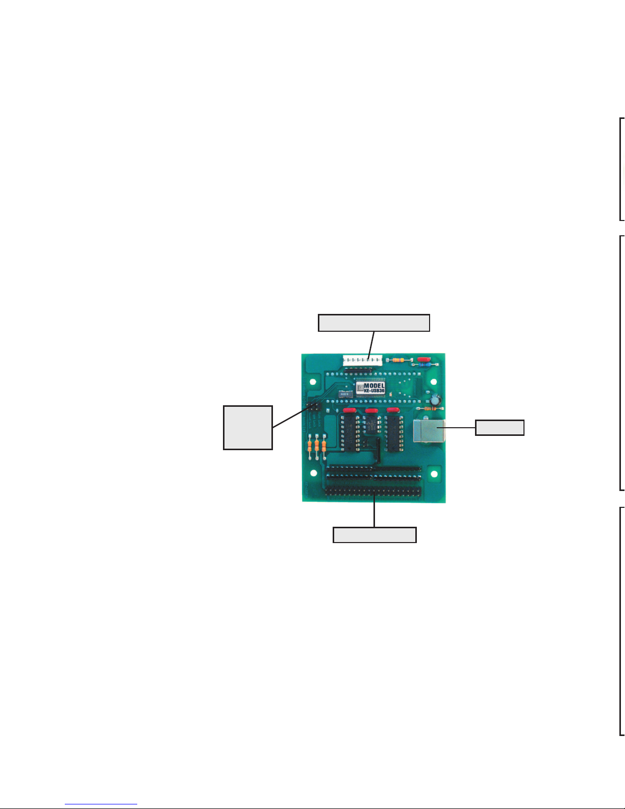
Introduction to the KE-USB36
The KE-USB36 Keyboard Encoder is a product designed to
interface switches or keypads to your computer’s USB port. The
KE-USB36 appears as both a keyboard and a mouse to your
computer system. The header inputs on the KE-USB36 may be
programmed to emulate any key from a standard keyboard. In
addition, any of the inputs may be programmed to emulate the
Left, Middle, and Right mouse buttons.
The KE-USB36 features a trackball interface port which allows
connection of the optical signals from a trackball to the unit. The
signals received on this port are converted into mouse movement
on the PC.
Note that you
are not required
to use both
interfaces on
the KE-USB36.
If you wish to
use the device
as a keyboard
interface only,
do not attach
to the trackball
i n t e r f a c e
connector. If
using the device as a trackball only, do not program any inputs
on the KE-USB36 input header as keyboard keys (you may still
program inputs as Left, Middle, and Right mouse buttons).
The KE-USB36 uses standard drivers for its functions. When using
the unit for the first time on your PC, you will be prompted to load
USB drivers for the device. Choose the default drivers that are
already present in your operating system.
USB Port
Trackball Input Header
Status
LED
Interface
36 Input Header
Accessories
We offer several accessories to connect to your KE-USB36.
breakout board. This product connects
Page 5
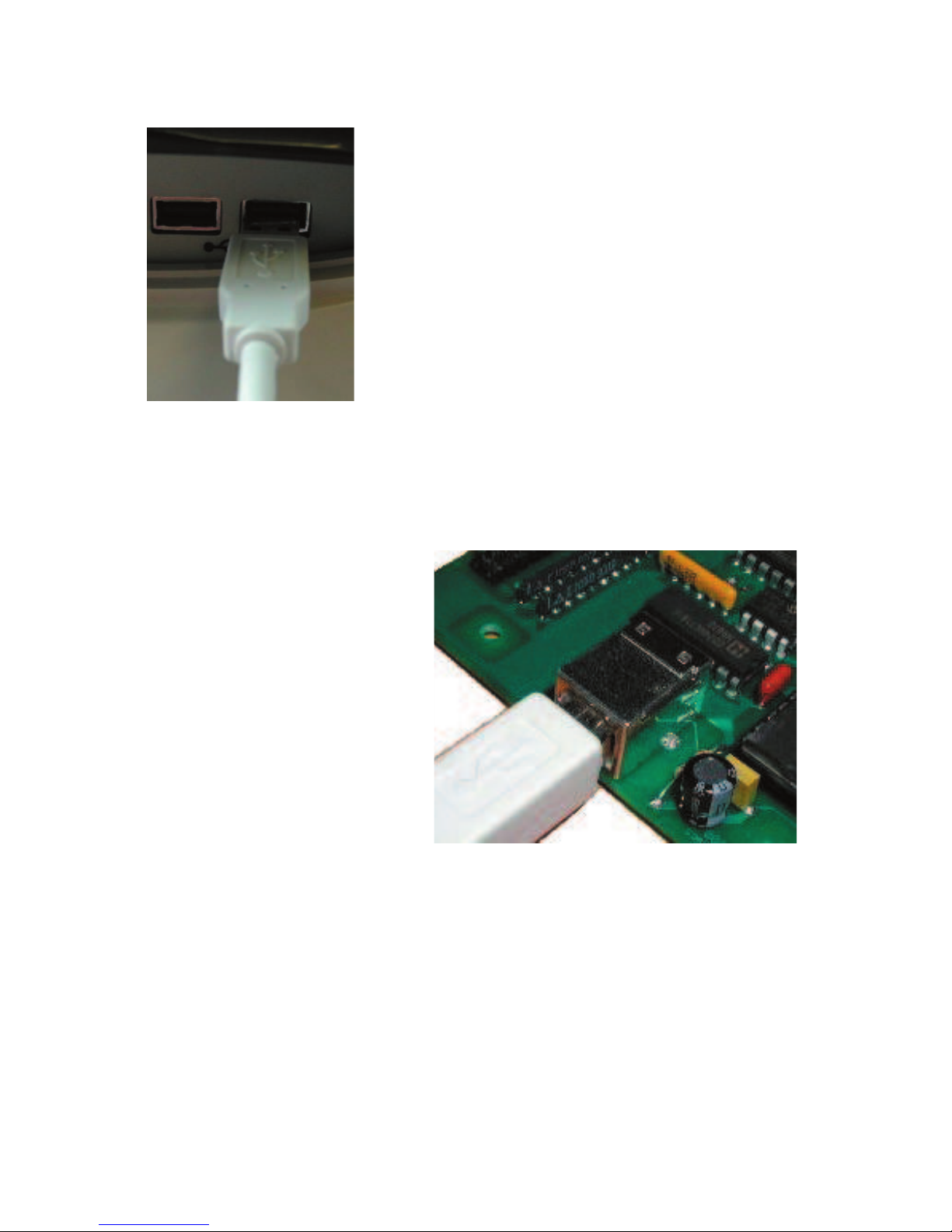
Connection to the Computer
The KE-USB36 attaches to your computer’s
USB port. Use a standard A-B Male/Male
type USB connecting cable from the KEUSB36 to the USB port on the computer.
The KE-USB36 may be connected directly
to the USB port on the PC or through a
compliant USB Hub.
Connect the type “B” end of the USB cable
into the KE-USB36 and the type “A” end
into the PC or HUB USB connector.
The KE-USB36 may be connected to the computer with power
on or off. If “hot plugged,” the unit will generally take several
seconds to become fully
active on your system.
Note: The first time you
use the KE-USB36 with
a particular PC, you will
be prompted to load the
appropriate drivers for the
device. Follow the default
selections to load the
standard drivers for the KEUSB36.
The KE-USB36 is powered directly from the USB port, so no
external power is required.
The KE-USB36 is compatible with operating systems which offer
full support for USB devices compliant to USB 1.0 specifications.
Consult the operating system manufacturer for information on
device compatibility and downloads.
Figure 2 - Connection of
the USB cable to PC
Figure 3 - Connection of the USB cable to
KE-USB36
516
Page 6
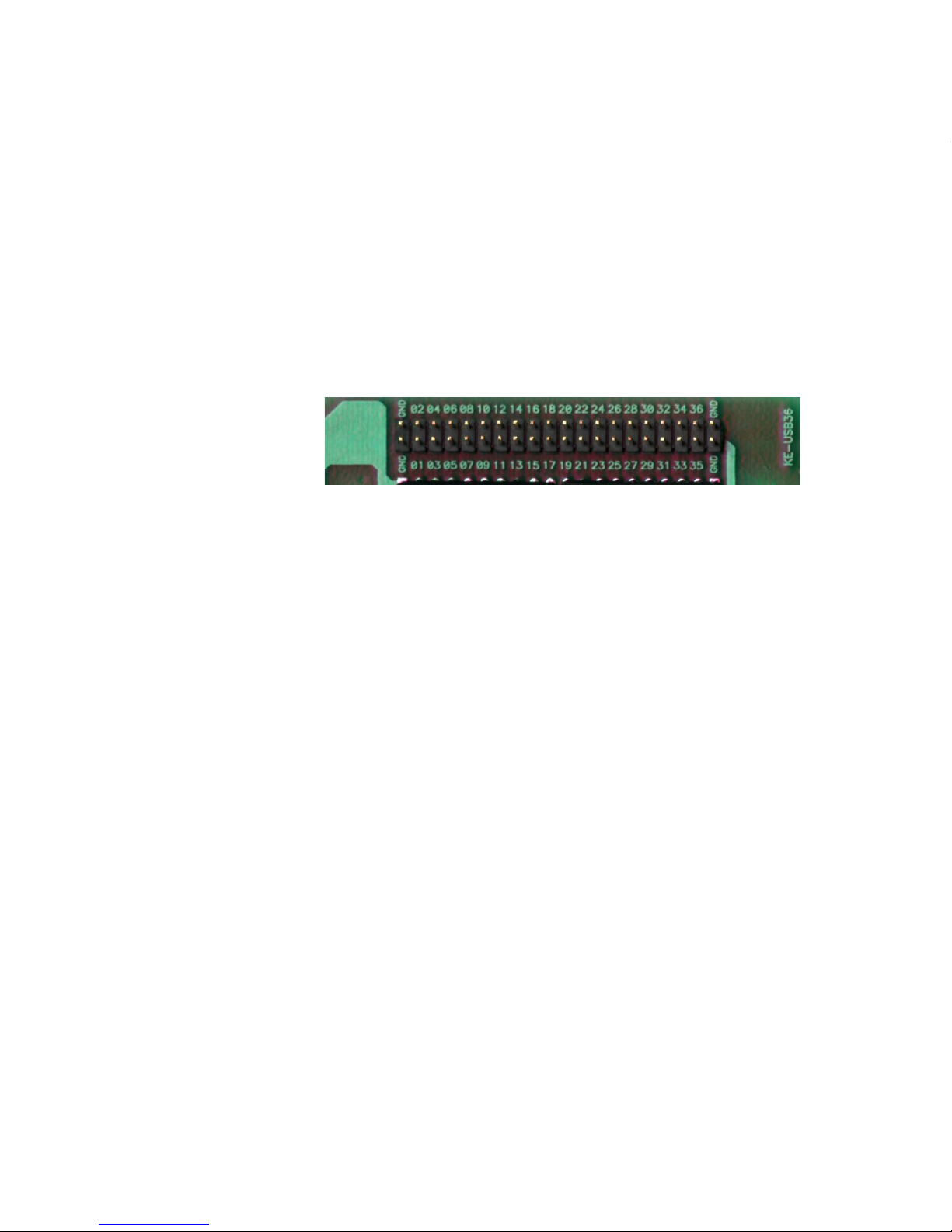
Interfacing to the KE-USB36 Input Header
The KE-USB36 features a 2x20 header for interface to your input
devices. The input header is arranged with grounds on the end
pins of the header, and the 36 inputs between them. The board
is labeled near each header pin, designating the input number
that the pin represents. Each of the pins may be programmed to
emulate any key on a standard PC keyboard as well as the Left,
Middle, and Right mouse buttons.
Inputs on the KE-USB36 header are activated by shorting them
to one of the
provided logic
grounds on the
header. When
activated, the
input will report the keystroke that it has been programmed to
emulate. If held active, the keystroke will repeat (if programmed
to repeat), based on the repeat rates and delays set within the
operating system.
The inputs are intended to handle mechanical switch inputs and
are debounced for that purpose. Logic drivers may be attached
to the inputs as well, provided they are an active low, logic level
signal. Refer to the Appendix A on specifications for the timing of
logic signals. Never attach any external power to the Inputs.
The KE-USB36 input header is a dual row header with .100”
spaced pins. This format is suitable for many readily available
connectors on the market, including a typical IDE hard drive cable.
Since all the inputs require the same logic ground reference, you
may “daisy chain” the ground to all of your switches. We also
offer a breakout board (our part number IOX36) for interface to
the KE-USB36. This interface board attaches to the KE-USB36
header through an IDE cable (provided with the IOX36). See
the accessories page of this manual for details on the IOX36.
Appendix B demonstrates connection techniques for switches on
Figure 4 - The KE-USB36 Input Header
a Trackball. Use the controls for either the X or Y axis for the
Spinner, according to the axis on which the Spinner movement is
to appear.
In order to accommodate the various brands of Trackballs, the
KE-USB36 provides check boxes to reverse the Left-Right and Up-
Down movements of the Trackball. If you find that one or both
directions of your cursor movement from the Trackball are reversed,
check the appropriate box in the configuration program.
The KE-USB36 uses the standard USB keyboard buffer length
which allows for up to six keys being reported “ON” at the same
time. This limitation only pertains to KE-USB36 inputs that are
programmed with the repeat selection enabled. Use of the Left and
Right Shift, Left and Right Alt, Left and Right Control, and Windows
GUI keys, can be used in addition to the six key limitation.
The KE-USB36 has the option of repeating an input that is held
on. If the input is selected to repeat, that input will count toward
the six key limit. Keys that are set to not produce a repeat will not
be subject to the 6 key limitation, provided there are no more
than 5 repeated keys currently active. Note that inputs defined as
mouse buttons do not figure into the six key limit.
Inputs on the KE-USB36 which emulate a multiple key sequence,
such as Shift+F1, will automatically have repeat disabled.
Appendix C:
KE-USB36 Read/Write from the Command Line
In addition to the KEUSB36.EXE configuration program, the CD
supplied with the KE-USB36 contains two command line programs
for reading from and writing to the KE-USB36 device. For details,
see the README.TXT file included on the CD.
Page 7

the KE-USB36.
Note: The KE-USB36 allows up to 6 keystroke inputs to be
activated simultaneously. This limitation does not include inputs
defined as Shift keys, Ctrl keys, Alt keys, Win GUI keys, or Mouse
Left, Middle, or Right Buttons.
Keyboard Status Light Signals
Keyboard status light drive is available with the KE-USB36. The unit
provides a 6 pin header for connection of the Num Lock, Caps
Lock, and Scroll Lock
status LEDs. As shown
below, the Anode and
Cathode connections for
these diodes are labeled
on the board near the 6
pin LED header.
As with the input header, this LED header is .100” spaced pins,
which is suitable for a variety of connectors. Soldering to the pins
is also an acceptable way to attach wires for connection to your
LEDs.
The KE-USB36 will drive on LED
directly from each Anode/Cathode
pair of wires. At 5 volts, the drive
current is approximately 10 ma
for each LED. The KE-USB36 has
current limiting resistors on the unit,
so connection to the user’s LED may
be made directly.
Figure 5 - Status LED connection
Figure 6 - Connection of LEDs to the
Status LED Header
714
Page 8

Interfacing to the KE-USB36 Trackball Header
The KE-USB36 features an interface connector which accepts
optical signals from a device such as a Spinner or a Trackball.
Power is supplied
to the trackball
interface from the
KE-USB36 for 5
volt operation only.
This interface is
compatible with the
most popular active
or passive Trackballs and Spinners currently on the market.
The Trackball header mates with the Hagstrom Electronics KETBH3 interface cable (see Accessories page of this manual).
In addition, the user may create their own cable using the pin
assignments as shown below.
Figure 7 - The KE-USB36 Trackball interface connector.
The connector features 8 pins spaced at .100” centers.
Figure 8 - Trackball Interface signal assignments.
Note: Do not supply any power into the Trackball interface connector.
Appendix A:
Specifi cations
Operating Voltage
Operating Current
Operating
Temperature
Input Header
Required Input
Current
Input Active Time
3.00
A1 = Y axis signal
5V = Power for Y axis
GND = Ground for Y axis
B1 = Y axis signal
A2 = X axis signal
5V = Power for X axis
GND = Ground for X axis
B2 = X axis signal
program window will display the device’s current configuration.
Note: Loading a configuration from the KE-USB36 will overwrite
any existing configuration settings in the program window.
Page 9

Configuring the KE-USB36
The KE-USB36 is supplied with a Windows utility program which
allows quick and easy setup of the inputs on the unit. Run the
KEUSB36.EXE utility program to start the configuration program.
The menu for the program appears as shown below.
The keystroke definitions for each input are shown in the key
definition box on the screen. The key definition box has the words
“Not Used” when the program initially starts. When inputs are
defined, the key definition box will then display the label for the
key to which that particular input is assigned.
The scroll bar may be used to access the definitions for all 36
inputs of the KE-USB36. Information pertaining to an input’s
keystroke definition is shown on each horizontal row.
To define a keystroke for an input, simply move to the line that
corresponds to the input number you wish to program, and select
the definition box to the right of the input number. Once selected,
an image of a standard keyboard is shown. Move your cursor to
the key which you want that particular input to emulate, and select
that key. The key you have selected will now appear in the key
912
Page 10

definition box for the input number you have chosen.
Use this same technique to define each of the inputs that you wish
to use in your configuration. In addition to specifying an input
to emulate a keystroke, inputs may also be defined as either the
Left, Middle, or Right mouse button. Select Left, Middle, or Right
mouse buttons when the keyboard selection diagram is shown to
define an input as a mouse button.
Note that a Trackball need not be attached to emulate the mouse
buttons. The KE-USB36 runs as both the mouse and the keyboard
at all times. If no Trackball device is connected to the unit, no
cursor movement will be initiated from the KE-USB36, but the
ability to emulate Left, Middle, or Right mouse buttons remains.
Any input defined as a keystroke may also be combined with
a Ctrl, Alt, or Shift function, or any combination of those three
modifiers. To initiate a Shift with the specified keystroke, simply
check the box marked “Shift” on the same line as that input. For
example, if you wish to emulate a Shift+F1 key, define the input
as an “F1” keystroke, then check the Shift box on that line. An
input with additional Ctrl,Alt, or Shift functions automatically has
repeat disabled.
When configured as shown above, Input #1 would perform a
Shift function along with the F1 keystroke. This combination would
be the equivalent of holding down the shift key on your keyboard
and then pressing F1.
Note that the Control, Alt, and Shift selection boxes are used in
combination with a key. If an input is to emulate only a Control,
Alt, or Shift, do not use these check boxes. Use the keys from
the Key selection diagram to program an input as one of these
modifiers keys (Control, Alt, or Shift).
If the input is to produce a repeated keystroke when held active,
the check box for the repeat function may be selected. When
active, the repeat function will perform a repeat of the selected
key exactly how your standard keyboard would handle a key held
down. The system settings dictate the repeat speed.
In addition to defining inputs, there are two check boxes for
adjusting the Trackball movement. Based on the type of Trackball
being used, one of the “Reverse Direction” check boxes may need
to be selected to get the proper Left-Right or Up-Down movement
from your Trackball.
Page 11

When configured as shown above, Input #1 would perform a
Shift function along with the F1 keystroke. This combination would
be the equivalent of holding down the shift key on your keyboard
and then pressing F1.
Note that the Control, Alt, and Shift selection boxes are used in
combination with a key. If an input is to emulate only a Control,
Alt, or Shift, do not use these check boxes. Use the keys from
the Key selection diagram to program an input as one of these
modifiers keys (Control, Alt, or Shift).
If the input is to produce a repeated keystroke when held active,
the check box for the repeat function may be selected. When
active, the repeat function will perform a repeat of the selected
key exactly how your standard keyboard would handle a key held
down. The system settings dictate the repeat speed.
In addition to defining inputs, there are two check boxes for
adjusting the Trackball movement. Based on the type of Trackball
being used, one of the “Reverse Direction” check boxes may need
to be selected to get the proper Left-Right or Up-Down movement
from your Trackball.
1110
Page 12

Configuring the KE-USB36
The KE-USB36 is supplied with a Windows utility program which
allows quick and easy setup of the inputs on the unit. Run the
KEUSB36.EXE utility program to start the configuration program.
The menu for the program appears as shown below.
The keystroke definitions for each input are shown in the key
definition box on the screen. The key definition box has the words
“Not Used” when the program initially starts. When inputs are
defined, the key definition box will then display the label for the
key to which that particular input is assigned.
The scroll bar may be used to access the definitions for all 36
inputs of the KE-USB36. Information pertaining to an input’s
keystroke definition is shown on each horizontal row.
To define a keystroke for an input, simply move to the line that
corresponds to the input number you wish to program, and select
the definition box to the right of the input number. Once selected,
an image of a standard keyboard is shown. Move your cursor to
the key which you want that particular input to emulate, and select
that key. The key you have selected will now appear in the key
Once the configuration has been created, it is recommended
that the configuration be saved to disk. The program provides an
option for saving the configuration as a custom disk file, so it may
be recalled at a later time for loading or modification.
To save the configuration to disk, select File, then Save As, and
specify a file name. Configurations saved at a prior time may be
recalled by using the Open selection and choosing a file from the
selection list.
To save the configuration to the KE-USB36, select File, then
Write to KEUSB36. Be sure that the KE-USB36 is connected to the
computer prior to this step. Once loaded, the new configuration
will take effect on the KE-USB36.
The configuration is stored on the KE-USB36 in non-volatile
memory. Once a configuration is loaded into the unit, it will
remain set (even during power off) until changed by the user.
To retrieve an existing configuration from the KE-USB36, select
File, then Read from KE-USB36. Be sure that the KE-USB36 is
connected to the computer prior to this step. Once loaded, the
Page 13

Appendix A:
Specifi cations
Operating Voltage
5 Volts DC +5%, -13%, Supplied from
USB port (Bus powered)
Operating Current
100 ma Maximum
Operating
Temperature
0 to 70 Degrees C
Input Header
2x20, with 36 individual inputs and
4 Ground connections. .025” square
pins spaced at .100”
Required Input
Current
1.2 ma sink current typical
Input Active Time
The input must be active for at least 20
msec to be considered valid.
3.25
3.00
.625
.625
.125
Dia (4)
Note: All dimensions are in inches.
138
program window will display the device’s current configuration.
Note: Loading a configuration from the KE-USB36 will overwrite
any existing configuration settings in the program window.
Page 14

the KE-USB36.
Note: The KE-USB36 allows up to 6 keystroke inputs to be
activated simultaneously. This limitation does not include inputs
defined as Shift keys, Ctrl keys, Alt keys, Win GUI keys, or Mouse
Left, Middle, or Right Buttons.
Keyboard Status Light Signals
Keyboard status light drive is available with the KE-USB36. The unit
provides a 6 pin header for connection of the Num Lock, Caps
Lock, and Scroll Lock
status LEDs. As shown
below, the Anode and
Cathode connections for
these diodes are labeled
on the board near the 6
pin LED header.
As with the input header, this LED header is .100” spaced pins,
which is suitable for a variety of connectors. Soldering to the pins
is also an acceptable way to attach wires for connection to your
LEDs.
Figure 6 - Connection of LEDs to the
Status LED Header
Appendix B:
Operating Tips
The KE-USB36 is configured as 36 individual inputs, which are
activated by shorting them to the common Ground provided on
the header. Since these inputs are individual, they are completely
separate, and cannot produce “ghosting” as in a matrix
application.
Inputs may also be driven from logic gates, provided they do not
drive voltage above the USB 5V supply on the unit. The logic
signals must produce an active logic low signal for the appropriate
amount of time as listed in Appendix A.
The recommended maximum cable length from the KE-USB36
input header to the input devices is 10 feet. The recommended
maximum cable length of the USB cable from the PC or Hub to
the KE-USB36 is 10 feet.
The Trackball header may be used for a Spinner instead of
Figure 14 - Electrical connection example for switches to
KE-USB36 header
Ground
Input 1
Input 2
Pushbutton
Pushbutton
KE-USB36 Header
Page 15

a Trackball. Use the controls for either the X or Y axis for the
Spinner, according to the axis on which the Spinner movement is
to appear.
In order to accommodate the various brands of Trackballs, the
KE-USB36 provides check boxes to reverse the Left-Right and UpDown movements of the Trackball. If you find that one or both
directions of your cursor movement from the Trackball are reversed,
check the appropriate box in the configuration program.
The KE-USB36 uses the standard USB keyboard buffer length
which allows for up to six keys being reported “ON” at the same
time. This limitation only pertains to KE-USB36 inputs that are
programmed with the repeat selection enabled. Use of the Left and
Right Shift, Left and Right Alt, Left and Right Control, and Windows
GUI keys, can be used in addition to the six key limitation.
The KE-USB36 has the option of repeating an input that is held
on. If the input is selected to repeat, that input will count toward
the six key limit. Keys that are set to not produce a repeat will not
be subject to the 6 key limitation, provided there are no more
than 5 repeated keys currently active. Note that inputs defined as
mouse buttons do not figure into the six key limit.
Inputs on the KE-USB36 which emulate a multiple key sequence,
such as Shift+F1, will automatically have repeat disabled.
Appendix C:
KE-USB36 Read/Write from the Command Line
In addition to the KEUSB36.EXE configuration program, the CD
supplied with the KE-USB36 contains two command line programs
for reading from and writing to the KE-USB36 device. For details,
see the README.TXT file included on the CD.
156
Page 16

Connection to the Computer
The KE-USB36 may be connected to the computer with power
on or off. If “hot plugged,” the unit will generally take several
seconds to become fully
active on your system.
Note: The first time you
use the KE-USB36 with
a particular PC, you will
be prompted to load the
appropriate drivers for the
device. Follow the default
selections to load the
standard drivers for the KE-
USB36.
The KE-USB36 is powered directly from the USB port, so no
external power is required.
The KE-USB36 is compatible with operating systems which offer
full support for USB devices compliant to USB 1.0 specifications.
Consult the operating system manufacturer for information on
device compatibility and downloads.
Figure 2 - Connection of
the USB cable to PC
Appendix D:
Board ID
Two KE-USB36 devices may be connected to the same machine.
Each KE-USB36 unit has a two position jumper which may be used
to identify the unit as #0 (primary) or #1 (secondary). BoardID is
0 or 1 based on the 2 position jumper setting on the board. ID 0
= Jumper Open (default). This jumper is located near the middle
of the KE-USB36 board and is the only 2 position jumper on the
unit (see figure 15).
Figure 15 - Location of two position BoardID
jumper.
Page 17

KE-TBH3
Trackball interface cable.
This cable attaches the KE-
USB36 Trackball input to the
Trackball itself.
Accessories
We offer several accessories to connect to your KE-USB36.
KE-USBMM6
6 ft. Male/Male Type
A to Type B USB
Cable
IOX36
Input Header to screw terminal
breakout board. This product connects
to the
KE-USB36
input
header
through a standard IDE cable
(included). Each input is brought
out to a separate, labeled, screw
terminal. Use for solderless
connection to the KE-USB36.
174
Page 18

Custom KE-USB36 Options
We offer custom modifications to our standard KE-USB36 unit
to conform to your exact specifications. We can add special
features such as matrix scanning, output controls, and display
interfaces, just to name a few. Give us a call to discuss your
custom requirements.
Matrix Scanning
Special Output Controls
LCD Interface
LED Interface
Rotary Switch Inputs
Serial Communication
Alternate Function Keys
Custom Machine Interfaces
Questions or Comments?
Please give us a call!
Toll Free
888-690-9080
or visit us on the web
www.hagstromelectronics.com
email: sales@hagstromelectronics.com
Introduction to the KE-USB36
Connection to the Computer
Interfacing to the KE-USB36 Input Header
Keyboard Status Light Signals
Interfacing to the KE-USB36 Trackball Header
Configuring the KE-USB36
Appendix A -
Appendix B - Operating Tips
Appendix C - KE-USB36 Read/Write from the Command Line
Appendix D - Board ID
Accessories
Custom KE-USB36 Options
18
Page 19

Warranty
HAGSTROM ELECTRONICS, INC. warrants this
product against defects in material or workmanship for a
period of ONE YEAR from the original purchase date. We will
repair or replace (at our option) the returned defective unit
at no charge during this warranty period.
No responsibility is assumed for any special, incidental,
or consequential damage resulting from the use of or
inability to use this product. In no case is HAGSTROM
ELECTRONICS, INC. to be liable for any amount which
exceeds the purchase price of the unit, regardless of the
claim.
No other warranty, written or verbal, is authorized. This
warranty is applicable only to units sold in the United States.
Units sold outside the United States are covered by a similar
warranty.
Depending on the state in which you live, you may have additional rights.
Great care has been taken during the assembly, testing, and burn-in of
your KE-USB36 to ensure its performance. If you have any questions,
please send us an email or give us a call. Support is available Monday
through Friday, 8:00 am to 5:00 pm (EST).
customer service email: sales@hagstromelectronics.com
Call Toll Free 888-690-9080, or (540) 465-4677
NOTICE The KE-USB36 product is designed to be used by technically
oriented computer users. When the KE-USB36 is in use, your computer’s
signals and voltages are present on the unit. Prudent handling and
packaging is necessary to prevent damage to your computer.
Your keyboard encoder is designed for OEM use, and is not FCC part 15 approved. Because
the packaging and use of the product will directly affect the characteristics of the unit, it is the
responsibility of the purchaser to obtain final approval of their application, if required.
Page 20

Toll Free 888-690-9080
Phone: (540) 465-4677 Fax: (540) 465-4678
Monday through Friday, 8:00 am to 5:00 pm (EST)
sales@hagstromelectronics.com
www.hagstromelectronics.com
1986 Junction Rd, Strasburg, VA 22657
Copyright © 2017 HAGSTROM ELECTRONICS, INC.
V. 07.16
HAGSTROM
ELECTRONICS, INC.
 Loading...