

Page 1

KEUSB24
PC Keyboard Encoder
User Manual
Page 2

Table of Contents
Introduction to the KEUSB24 1
Computer Connections and Device ID Jumper 2
Interfacing to the KEUSB24 I/O Header 3
Status LED Connections 4
The KEUSB24.EXE Program 4
The Program Screen 5
File Menu Selections 7
Sample KEUSB24 Confi guration 9
Error Messages 16
KEUSB24 Operating Tips 18
Appendix A: Specifi cations 19
Appendix B: Command Line Loader 20
Accessories 20
Thank you for purchasing the
HAGSTROM ELECTRONICS, INC.
KEUSB24. This product is confi gurable
in a variety of ways to meet your specifi c
requirements. Please take a few minutes to
read this manual before using your KEUSB24.
HAGSTROM ELECTRONICS, INC. warrants this
product against defects in material or workmanship for a
period of ONE YEAR from the original purchase date. We will
repair or replace (at our option) the returned defective unit
at no charge during this warranty period.
No responsibility is assumed for any special, incidental,
or consequential damage resulting from the use of or
inability to use this product. In no case is HAGSTROM
ELECTRONICS, INC. to be liable for any amount which
exceeds the purchase price of the unit, regardless of the
claim.
No other warranty, written or verbal, is authorized. This
warranty is applicable only to units sold in the United States.
Units sold outside the United States are covered by a similar
warranty.
Depending on the state in which you live, you may have additional rights.
Great care has been taken during the assembly, testing, and burn-in
of your KEUSB24 to ensure its performance. If you have any questions,
please send us an email or give us a call. Support is available Monday
through Friday, 8:00 am to 5:00 pm (EST).
customer service email: sales@hagstromelectronics.com
Call Toll Free 888-690-9080, or (540) 465-4677
NOTICE The KEUSB24 product is designed to be used by technically
oriented computer users. When th e KEUSB24 i s in use, y o ur computer’s
signals and voltages are present on the unit. Prudent handling and
packaging is necessary to prevent damage to your computer.
Your keyboard encoder is designed for OEM use, and is not FCC part 15 approved. Because
the packaging and use of the product will directly affect the characteristics of the unit, it is the
responsibility of the purchaser to obtain fi nal approval of their application, if required.
Page 3

1
Introduction to the KEUSB24
Our KEUSB24 Keyboard Encoder is a product designed to interface
Keypads, Switches, and/or other contact closures to the computer’s
USB port. Devices connected to the KEUSB24 I/O header produce
keystrokes that appear to the PC as if they were entered from a
standard USB keyboard.
The KEUSB24 is fully programmable by the user. This p rogrammability
feature allows the confi guration of the I/O as well as the selection
of the keystrokes that will be sent to the PC. The KEUSB24 stores
the user’s confi guration program in non-volatile memory so that the
information is retained on the unit even after power is turned off.
The KEUSB24 I/O
The 2 x 25 pin dual row header provides 24 I/O signals that can be
programmed to scan any size matrix up to 12 Columns x 12 Rows.
Any of the 24 I/O pins may be designated as either a Column or a
Row. The KEUSB24 confi gures its scanning to the keypad, allowing
the direct connection of many “off the shelf” keypads without any
modifi ed or complicated cabling.
Power Requirements
The KEUSB24 requires no external power source. It is powered directly
from the USB port on the PC.
Supported Computers
All PCs with a standard USB port will work with the KEUSB24. The
KEUSB24.EXE Program is for Windows based systems.
Hardware Requirements
The KEUSB24 is designed to work with standard, commercially
available cables for connection to the PC. An A-B Type USB cable is
required for this connection.
Default Settings
The KEUSB24 is programmed and shipped with a default 4x4 matrix
confi guration. This default confi guration can be changed or modifi ed
at any time by the user.
Page 4
Operating Voltage
Operating Current
Operating Temp.
PC Interface
Input Debounce Time
I/O Header
2.0”
2
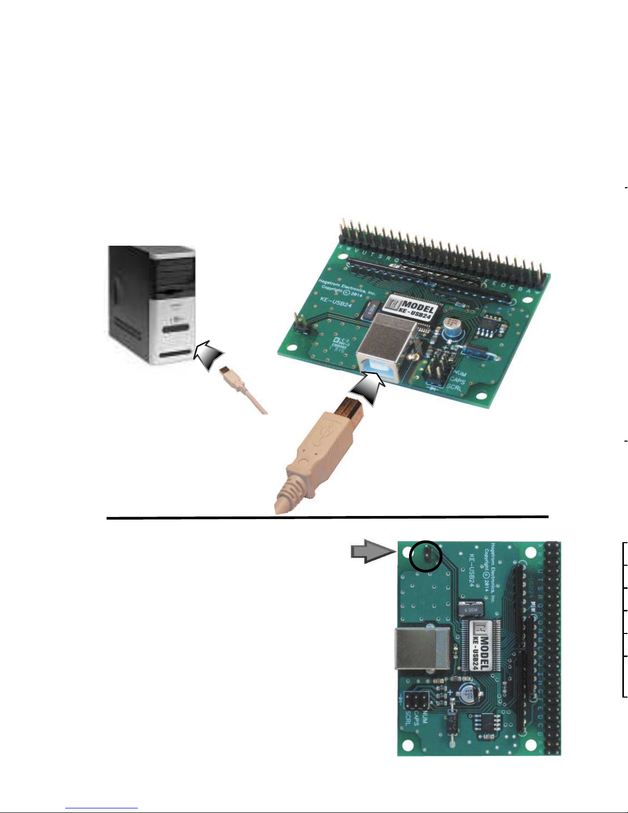
Computer Connection
There is one USB connector located on th e KEUSB24. Connection
to this port can be made with power on as the KEUSB24 supports
“Hot Plug” operation as a USB device.
The KEUSB24 emulates a standard 104 key USB keyboard
and may be used in addition to or in place of the system’s own
keyboard.
Device ID Jumper
Two KEUSB24 units may be connected
to the same computer and programmed
independently. If using one unit, leave
the Device ID jumper open (factory
default). If using two KEUSB24 units,
leave the jumper open on unit 1, and
closed on unit 2. This setup will present
two different USB devices to the system
that both work as USB keyboards.
Page 5
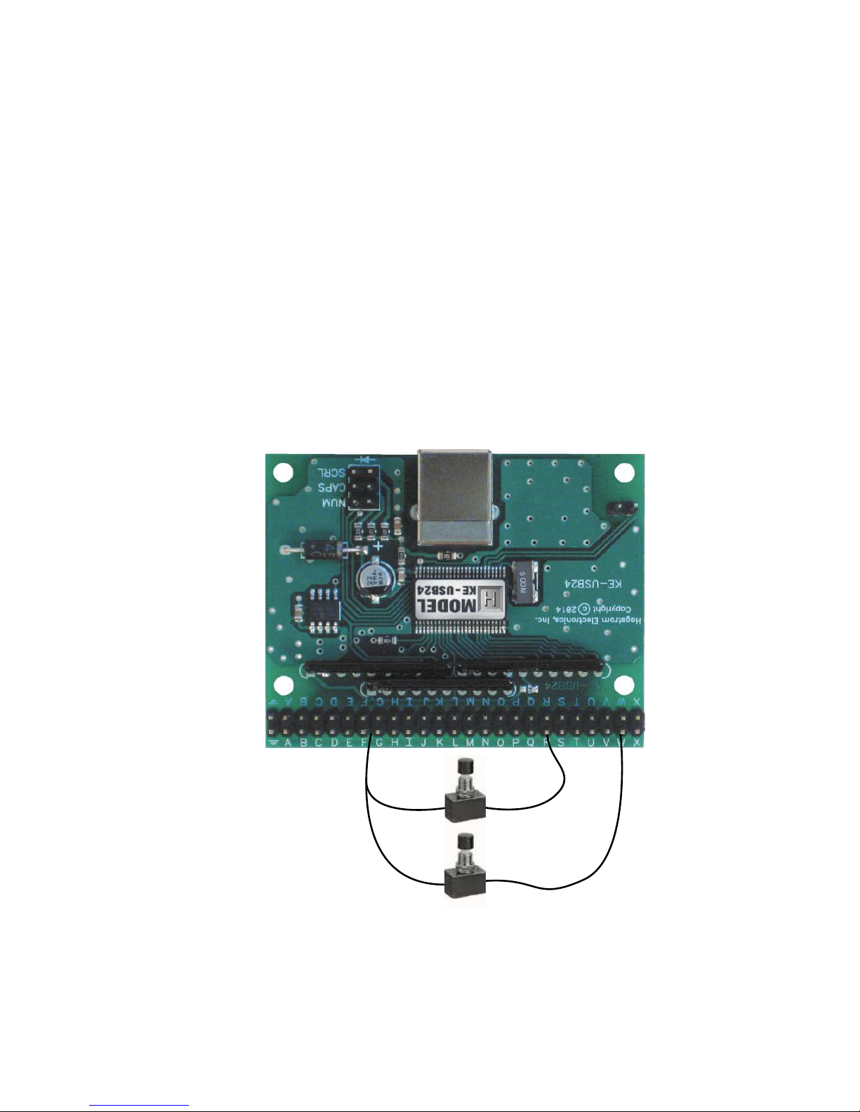
Interfacing to the KEUSB24 I/O Header
The 2 x 25 pin dual row header on the KEUSB24 consists of 24
I/O pins with a Logic Ground at one end. The I/O signals are
labeled on the KEUSB24 as “A” through “X”. Each pin on the
dual row header is connected in parallel with its adjacent pin.
Therefore, each I/O signal is available on two different pins.
Use the supplied KEUSB24.EXE program to confi gure th e I/O pins
as either Rows or Columns. Keystrokes are initiated by shorting
a Row pin to a Column pin through a contact closure. The pins
that are defi ned as Columns will sink current while scanning the
matrix. The Rows are used to read the status of the inputs when
a Column is active.
*Note:
The switch, keypad, or input device that is used must
be capable of carrying at least 1mA of current. In addition to
switches and keypads, other electronic circuits may also be used
to generate keystrokes, provided that they do not exceed the 5
volt logic level range of the KEUSB24 I/O.
3
Figure 1.1
Inputs are activated by
shorting a pin defi ned
as a Row to a pin
defi ned as a Column.
Column
Column
Row
Page 6
“Error saving fi le”
This error message is shown if the KEUSB24.EXE program
attempts to save a fi le t hat is already open in another application,
or if there is not enough disk space. If this happens, close the
other application and try saving the fi le again.
“Error: Pin * is used for multiple scan lines”
If a header pin is used to designate more than one row or column
or is used for both a row and a column, this error will be displayed
when saving the confi guration to a fi le or to the KEUSB24. Check
the matrix confi guration and eliminate redudant pin letters.
The error message will give the letter of the problematic pin
(Example: “Error: Pin D is used for multiple scan lines”).
The KEUSB24.EXE Program
The KEUSB24 unit is shipped with a CD ROM containing the
KEUSB24.EXE utility program which is used for confi guring the
unit. Confi guration parameters include the defi ning of the I/O
pins as Rows and Columns, the keystrokes generated by the
contact closures, as well as other various options.
Getting Started
To begin using the KEUSB24, follow the steps listed below.
1. Attach the KEUSB24 to the computer as described on
page 2 under the section “Computer Connections.”
2. Insert the CD and save the content to its own folder
on the hard drive. The CD may now be removed and
stored in a safe location for future use.
3. Open the folder that was created in step 2 and start
the confi guration program by selecting the program
fi le KEUSB24.EXE.
*Note:
The programs must be copied to and run from its own
folder on the PC’s hard drive. The CD itself should be reserved
for back up purposes only.
4
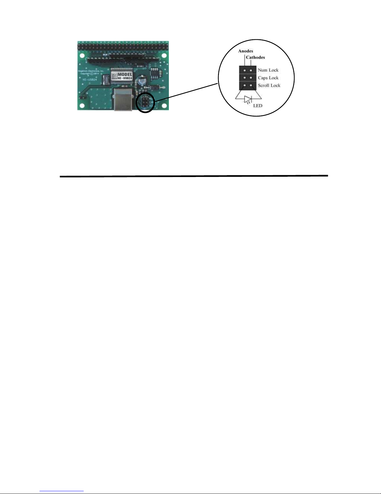
Status LED Connections
The KEUSB24 features a 2 x 3 header for driving the three status
LEDs for Num, Caps, and Scroll Lock. Connect LEDs as shown to
use this drive capability. No external current limiting resistors are
required as they are supplied on the board.
Page 7
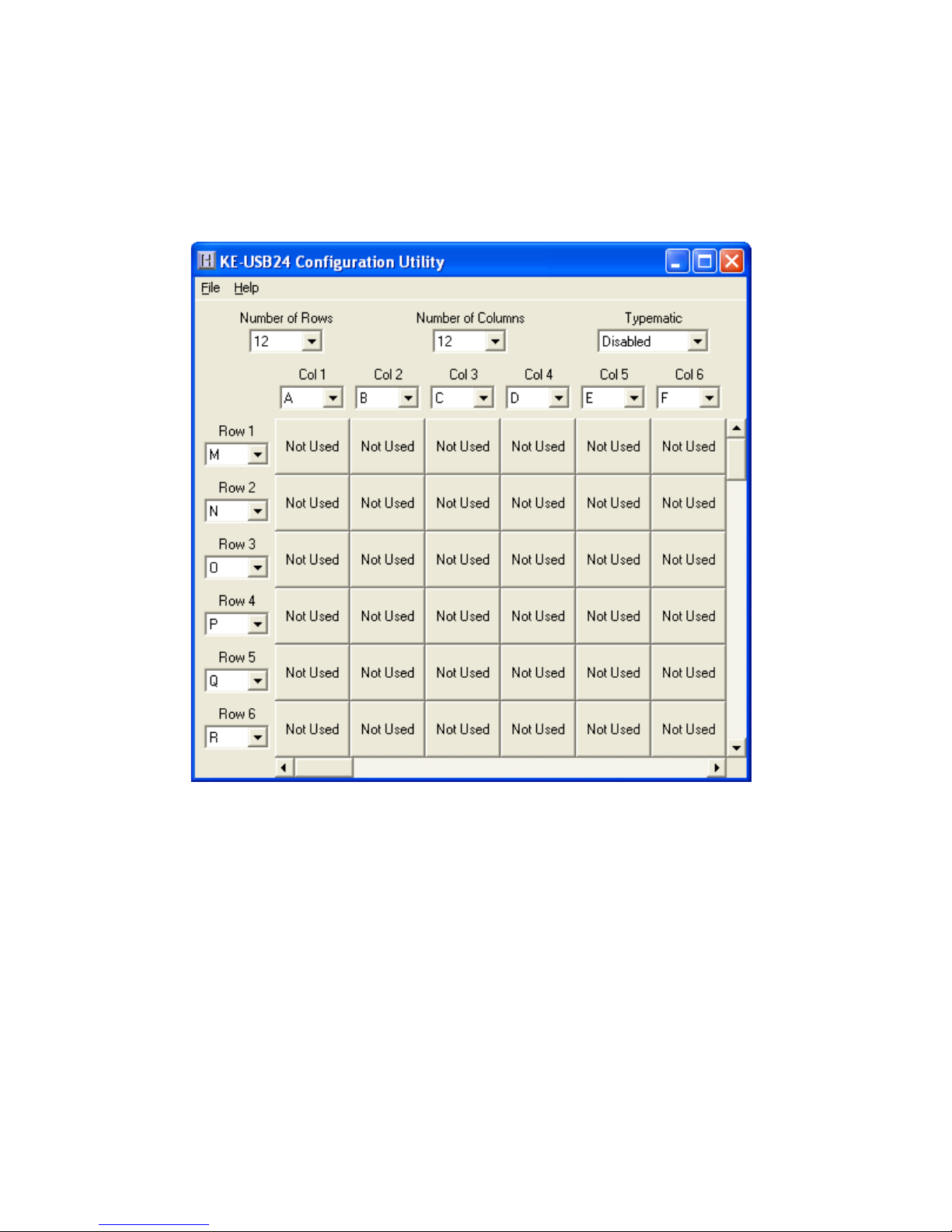
The Program Screen
The main program screen displays the confi guration settings for
the KEUSB24. A list of these settings and a description of how
they pertain to the KEUSB24 setup are listed below.
*Note:
The number of Rows plus the number of Columns
cannot exceed the total number of 24 I/O pins. For example, 5
Rows + 12 Columns = 17 I/O pins.
Number of Rows: The number of Rows are selected from
the drop down list. This may be any value from 1 to 23.
Number of Columns: The number of Columns are selected
from the drop down list. This may be any value from 1 to 23.
5
Page 8

Step 5
Now that the setup is complete, it can be saved to disk. Specify
a fi le name under which to save the confi guration.
Step 6
Load the KEUSB24 with the confi guration. Be sure that the
KEUSB24 is connected to the PC. Once the KEUSB24 is loaded,
it will begin running the new setup.
Typematic: The typematic option controls the enable or
disable of the KEUSB24 repeat function. Typically on a PC
keyboard when a key is held down, it will begin to repeat after
a short delay. This function can be duplicated by the devices
connected to the KEUSB24 I/O header by enabling this option.
Enabling this option will affect all keys within the matrix. The
rate at which the key will repeat is the same as your PC keyboard
settings on the PC. With this option disabled, the keystrokes
being generated from the devices attached to the KEUSB24 will
produce one keystroke per activation.
*Note:
The Typematic Enable/Disable option only applies to
the devices connected to the KEUSB24 I/O header. It will not
affect the repeat functions of the PC keyboard.
Column Pin Assignments: Column pin assignments are
selected from their corresponding drop down list. Each column
must have an I/O pin assigned to it. Specify any I/O pin “A”
through “X” as a column.
Row Pin Assignments: Row pin assignments are selected
from their corresponding drop down list. Each row must have an
I/O pin assigned to it. Specify any I/O pin “A” through “X” as a
row.
*Note: A pin cannot be assigned to both a Column and a
Row.
6
Page 9

File Menu Selections
These selections, located within a drop down list, are accessed
by clicking on “File” in the upper left corner of the main program
screen. This list provides several options that include creating
and saving fi le confi gurations as well as reading and writing to
the KEUSB24. A list of these options along with descriptions of
how they pertain to the KEUSB24 setup are listed below.
7
New: Creates a new confi guration fi le by either clicking on
“New” with the mouse or by pressing Ctrl+N on the keyboard.
This option will also return the program screen to the default
settings.
Page 10

Step 4
The KEUSB24 has the capability to assign Shift, Ctrl, and Alt
functions along with a keystroke. For this sample setup, one of
the keys is defi ned as the Ctrl+Alt+Del sequence. The keystrokes
emulated by this combination have the same effect as holding
the control and alt keys, then pressing the delete key on a PC
keyboard. To create this input, check the Ctrl and Alt boxes on
the lower left corner of the keyboard diagram, then click on the
Del button (shown below).
Any position in the KEUSB24 matrix can be modifi ed by one or a
combination of two of the Shift, Alt, or Ctrl keys using the method
described above. Use the Shift function to generate upper case
characters, or shifted characters (!, @, etc.) in the application. To
remove one of these special functions, uncheck the appropriate
box and click on the desired key.
Open: Recall a previously saved confi guration fi le by either
clicking on “Open” with the mouse or by pressing Ctrl+O on the
keyboard. Locate and select the name of the confi guration fi le
on the PC that is to be opened.
Save: Once a confi guration setup has been created on the
program screen, it is recommended that it be saved on the PC’s
hard disk. Click on “Save” with the mouse or press Ctrl+S on the
keyboard, then choose a location to save the fi le.
Read from K EUSB24 (1): This option will read the current
confi guration in the KEUSB24 and display it on the screen. Click
on “Read from KEUSB24” with the mouse or press Ctrl+R on the
keyboard to perform this operation.
Write to KEUSB24 (1): This option will write the current
confi guration displayed on the screen to the KEUSB24. The
KEUSB24 can be programmed and re-programmed as many
times as necessary. Click on “Write to KEUSB24” with the mouse
or press Ctrl+W on the keyboard to perform this operation. After
the KEUSB24 has been loaded with the new confi guration, it will
scan according to this new setup.
Read from K EUSB24 (2): This option will read the current
confi guration from a unit confi gured as Device ID 2.
Write to KEUSB24 (2): This option will write the current
confi guration from a unit confi gured as Device ID 2.
Exit: This option exits and closes the KEUSB24.EXE program.
*Note:
Make sure that the KEUSB24 is connected to the PC
before performing either the “Read to KEUSB24” or “Write to
KEUSB24” operations. If the KEUSB24 is not present, a “The
KEUSB24 was not Found” error will be displayed on the computer
screen.
Page 11

Sample KEUSB24 Confi guration
The following exercise demonstrates how to program the
KEUSB24 to scan a keypad. The keypad in the example is a 4x4
matrix (16 key) device.
Step 1
Select the Number of Rows on the screen and set it to 4. Select
the Number of Columns, and set that value to 4 as well. The
screen should appear as shown below.
912
Page 12

10
Step 2
Now that the size of the matrix to be scanned has been selected,
the pins of the KEUSB24 I/O header to be used as rows and
columns must be selected. The keypad example has 8 interface
pins. The easiest way to plug the keypad in is to attach it 1:1 to
the I/O header. For this example, the header pins “A” through
“H” are used as the connection point.
*Note:
Any 8 of the KEUSB24 pins could have been used for
this example.
Since the Columns and Rows for the example keypad are
intermixed, the pin defi nitions for the Rows and Columns must
be assigned. Highlight the Column pin designations, and assign
them as follows:
Col 1 = Pin D, Col 2 = Pin A, Col 3 = Pin G, Col 4 = Pin H
Select the Row Pin defi nitions next, and change them to:
Row 1 = Pin E, Row 2 = Pin C, Row 3 = Pin F, Row 4 = Pin B
Step 3
With the size o f th e matrix now defi ned, and th e I/O pins selected,
assign the keys to be emulated to each position in the matrix.
To assign keys, click on the desired matrix position. A diagram
of the keyboard will be displayed, as shown below. Click on the
representation of the key to assign it to the matrix position.
Page 13

Step 3
With the size o f th e matrix now defi ned, and th e I/O pins selected,
assign the keys to be emulated to each position in the matrix.
To assign keys, click on the desired matrix position. A diagram
of the keyboard will be displayed, as shown below. Click on the
representation of the key to assign it to the matrix position.
11
Page 14

Sample KEUSB24 Confi guration
The following exercise demonstrates how to program the
KEUSB24 to scan a keypad. The keypad in the example is a 4x4
matrix (16 key) device.
Step 1
Select the Number of Rows on the screen and set it to 4. Select
the Number of Columns, and set that value to 4 as well. The
screen should appear as shown below.
Continue selecting each position in the matrix and assign the
desired keys from the keyboard diagram until the matrix is
fi nished.
In the example illustrations, the user clicked matrix position
Row 1, Col 3 and assigned the key “C” to it.
Page 15

Step 4
The KEUSB24 has the capability to assign Shift, Ctrl, and Alt
functions along with a keystroke. For this sample setup, one of
the keys is defi ned as the Ctrl+Alt+Del sequence. The keystrokes
emulated by this combination have the same effect as holding
the control and alt keys, then pressing the delete key on a PC
keyboard. To create this input, check the Ctrl and Alt boxes on
the lower left corner of the keyboard diagram, then click on the
Del button (shown below).
Any position in the KEUSB24 matrix can be modifi ed by one or a
combination of two of the Shift, Alt, or Ctrl keys using the method
described above. Use the Shift function to generate upper case
characters, or shifted characters (!, @, etc.) in the application. To
remove one of these special functions, uncheck the appropriate
box and click on the desired key.
138
Page 16

These selections, located within a drop down list, are accessed
by clicking on “File” in the upper left corner of the main program
screen. This list provides several options that include creating
and saving fi le confi gurations as well as reading and writing to
the KEUSB24. A list of these options along with descriptions of
how they pertain to the KEUSB24 setup are listed below.
New: Creates a new confi guration fi le by either clicking on
“New” with the mouse or by pressing Ctrl+N on the keyboard.
This option will also return the program screen to the default
settings.
14
The following diagram shows the completed setup created in
this example. Note the presence of modifi er keys in Row 4, Col
3 and Row 4, Col 4.
Page 17

Step 5
Now that the setup is complete, it can be saved to disk. Specify
a fi le name under which to save the confi guration.
Step 6
Load the KEUSB24 with the confi guration. Be sure that the
KEUSB24 is connected to the PC. Once the KEUSB24 is loaded,
it will begin running the new setup.
15
Page 18

The main program screen displays the confi guration settings for
the KEUSB24. A list of these settings and a description of how
they pertain to the KEUSB24 setup are listed below.
*Note:
cannot exceed the total number of 24 I/O pins. For example, 5
Rows + 12 Columns = 17 I/O pins.
Number of Rows: The number of Rows are selected from
the drop down list. This may be any value from 1 to 23.
Number of Columns: The number of Columns are selected
from the drop down list. This may be any value from 1 to 23.
Error Messages
“The KEUSB24 was not found”
This error occurs if the computer cannot communicate with the
KEUSB24 when trying to save to the KEUSB24 or read from the
KEUSB24. Check the cable connections to make sure none of
them are loose or unplugged. Check the Device ID jumper.
“Error while reading from the KEUSB24”
“Error while writing to the KEUSB24”
This indicates that, while the computer can communicate with
the KEUSB24, it was not able to read or write the confi guration.
Communication may be interrupted if a user presses a key on
the keyboard or if another program takes the focus away from
the KEUSB24 application. If this error message is displayed,
load the confi guration again.
16
“Invalid confi guration”
“Invalid confi guration fi le”
When loading an already existing confi guration from a fi le or
uploading a confi guration from the KEUSB24, the program will
give this error message if the fi le is corrupted or if it is the wrong
fi le type.
“Error opening the fi le”
This error message is shown if the KEUSB24.EXE program
attempts to o p en a fi le t h at is already open i n another application.
If this happens, close the other application and open the fi le
again.
Page 19

17
“Error saving fi le”
This error message is shown if the KEUSB24.EXE program
attempts to save a fi le t hat is already open in another application,
or if there is not enough disk space. If this happens, close the
other application and try saving the fi le again.
“Error: Pin * is used for multiple scan lines”
If a header pin is used to designate more than one row or column
or is used for both a row and a column, this error will be displayed
when saving the confi guration to a fi le or to the KEUSB24. Check
the matrix confi guration and eliminate redudant pin letters.
The error message will give the letter of the problematic pin
(Example: “Error: Pin D is used for multiple scan lines”).
Page 20

KEUSB24 Operating Tips
Please check the following items before contacting us.
• When connecting the KEUSB24 to a PC use a standard
USB A-B type Cable.
• Check the KEUSB24 confi guration. Check the I/O
confi guration for the number of Columns, Rows, etc.
Review the matrix table for the desired responses.
• The maximum recommended cable length from the
computer to the KEUSB24 is 10 feet. This distance is also
the maximum length that should be used on connections
from the switches or keypads to the KEUSB24 I/O
header.
• If using a Device ID jumper, only make changes to
it when the power to the unit is off as it is sampled at
power on or reset.
• While the KEUSB24 only scans a matrix, running a
1 x 23 matrix essentially provides 23 individual inputs
without the inherent matrix issues.
*Note:
For any questions that are not answered in this
manual, please send us an email or call customer service. We
have customer service available from 8:00 am to 5:00 pm (EST)
Monday through Friday.
customer service email: sales@hagstromelectronics.com
Toll Free 888-690-9080, or (540) 465-4677
Interfacing to the KEUSB24 I/O Header
The 2 x 25 pin dual row header on the KEUSB24 consists of 24
I/O pins with a Logic Ground at one end. The I/O signals are
labeled on the KEUSB24 as “A” through “X”. Each pin on the
dual row header is connected in parallel with its adjacent pin.
Therefore, each I/O signal is available on two different pins.
Use the supplied KEUSB24.EXE program to confi gure th e I/O pins
as either Rows or Columns. Keystrokes are initiated by shorting
a Row pin to a Column pin through a contact closure. The pins
that are defi ned as Columns will sink current while scanning the
matrix. The Rows are used to read the status of the inputs when
a Column is active.
*Note:
be capable of carrying at least 1mA of current. In addition to
switches and keypads, other electronic circuits may also be used
to generate keystrokes, provided that they do not exceed the 5
volt logic level range of the KEUSB24 I/O.
Inputs are activated by
shorting a pin defi ned
as a Row to a pin
defi ned as a Column.
18
Page 21

Operating Voltage
5 Volts DC +/- 5%
Operating Current
12 ma Typical
Operating Temp.
0 to 70 Degrees C
PC Interface
USB
Input Debounce Time
15 - 20 Msec Typical
I/O Header
24 I/O, up to 12x12 Matrix
(programmable)
Appendix A:
KEUSB24 Specifi cations
2.0”
2.5”
.125
Dia. (4)
19
Page 22

Our KEUSB24 Keyboard Encoder is a product designed to interface
Keypads, Switches, and/or other contact closures to the computer’s
USB port. Devices connected to the KEUSB24 I/O header produce
keystrokes that appear to the PC as if they were entered from a
standard USB keyboard.
The KEUSB24 is fully programmable by the user. This p rogrammability
feature allows the confi guration of the I/O as well as the selection
of the keystrokes that will be sent to the PC. The KEUSB24 stores
the user’s confi guration program in non-volatile memory so that the
information is retained on the unit even after power is turned off.
The KEUSB24 I/O
The 2 x 25 pin dual row header provides 24 I/O signals that can be
programmed to scan any size matrix up to 12 Columns x 12 Rows.
Any of the 24 I/O pins may be designated as either a Column or a
Row. The KEUSB24 confi gures its scanning to the keypad, allowing
the direct connection of many “off the shelf” keypads without any
modifi ed or complicated cabling.
Power Requirements
The KEUSB24 requires no external power source. It is powered directly
from the USB port on the PC.
Supported Computers
All PCs with a standard USB port will work with the KEUSB24. The
KEUSB24.EXE Program is for Windows based systems.
Hardware Requirements
The KEUSB24 is designed to work with standard, commercially
available cables for connection to the PC. An A-B Type USB cable is
required for this connection.
Default Settings
The KEUSB24 is programmed and shipped with a default 4x4 matrix
confi guration. This default confi guration can be changed or modifi ed
at any time by the user.
Accessories
20
KE-USBMM6
6 foot USB Type A to Type B connecting
cable between KEUSB24 and PC.
MTA100-12-12
MTA Harness to connect to the KEUSB24
header. Features a right angle connector
that plugs directly to the I/O header, and
provides 12 inches of discrete wire for
each header pin.
MTA100-12-12
KEUSB24 Header
Appendix B:
Command Line Loader
The KEUSB24 can also be loaded through the command line by using
the supplied KEUSB24LOAD.EXE program. Refer to readme.txt located
under the Command Line Loader folder on the supplied CD ROM for
further details.
Page 23

Warranty
HAGSTROM ELECTRONICS, INC. warrants this
product against defects in material or workmanship for a
period of ONE YEAR from the original purchase date. We will
repair or replace (at our option) the returned defective unit
at no charge during this warranty period.
No responsibility is assumed for any special, incidental,
or consequential damage resulting from the use of or
inability to use this product. In no case is HAGSTROM
ELECTRONICS, INC. to be liable for any amount which
exceeds the purchase price of the unit, regardless of the
claim.
No other warranty, written or verbal, is authorized. This
warranty is applicable only to units sold in the United States.
Units sold outside the United States are covered by a similar
warranty.
Depending on the state in which you live, you may have additional rights.
Great care has been taken during the assembly, testing, and burn-in
of your KEUSB24 to ensure its performance. If you have any questions,
please send us an email or give us a call. Support is available Monday
through Friday, 8:00 am to 5:00 pm (EST).
customer service email: sales@hagstromelectronics.com
Call Toll Free 888-690-9080, or (540) 465-4677
NOTICE The KEUSB24 product is designed to be used by technically
oriented computer users. When th e KEUSB24 i s in use, y o ur computer’s
signals and voltages are present on the unit. Prudent handling and
packaging is necessary to prevent damage to your computer.
Your keyboard encoder is designed for OEM use, and is not FCC part 15 approved. Because
the packaging and use of the product will directly affect the characteristics of the unit, it is the
responsibility of the purchaser to obtain fi nal approval of their application, if required.
Page 24

Toll Free 888-690-9080
Phone: (540) 465-4677 Fax: (540) 465-4678
Monday through Friday, 8:00 am to 5:00 pm (EST)
sales@hagstromelectronics.com
www.hagstromelectronics.com
1986 Junction Road, Strasburg, VA 22657
Copyright © 2017 HAGSTROM ELECTRONICS, INC.
V. 07.16
HAGSTROM
ELECTRONICS, INC.
 Loading...