

Page 1

KEAD6
USB Joystick Interface
and Keyboard Encoder
User Manual
Page 2

Table of Contents
Introduction to the KEAD6 1
Computer Connections and Device ID Jumper 2
Interfacing to the KEAD6 3
The KEAD6.EXE Program 4
The Program Screen 5
File Menu Selections 6
Options Menu Selections 8
Confi guring the KEAD6 9
KEAD6 Operating Tips 19
Error Messages 20
Appendix A: KEAD6 Specifi cations 22
Appendix B: Using the KEAD6 with Custom Software 23
Accessories 24
Thank you for purchasing the
HAGSTROM ELECTRONICS, INC.
KEAD6. This product is confi gurable in a variety
of ways to meet your specifi c requirements.
Please take a few minutes to read this manual
before using your KEAD6.
HAGSTROM ELECTRONICS, INC. warrants this
product against defects in material or workmanship for a
period of ONE YEAR from the original purchase date. We will
repair or replace (at our option) the returned defective unit
at no charge during this warranty period.
No responsibility is assumed for any special, incidental,
or consequential damage resulting from the use of or
inability to use this product. In no case is HAGSTROM
ELECTRONICS, INC. to be liable for any amount which
exceeds the purchase price of the unit, regardless of the
claim.
No other warranty, written or verbal, is authorized. This
warranty is applicable only to units sold in the United States.
Units sold outside the United States are covered by a similar
warranty.
Depending on the state in which you live, you may have additional rights.
Great care has been taken during the assembly, testing, and burn-in
of your KEAD6 to ensure its performance. If you have any questions,
please send us an email or give us a call. Support is available Monday
through Friday, 8:00 am to 5:00 pm (EST).
customer service email: sales@hagstromelectronics.com
Call Toll Free 888-690-9080, or (540) 465-4677
NOTICE The KEAD6 product is designed to be used by technically
oriented computer users. When the KEAD6 is in use, your computer’s
signals and voltages are present on the unit. Prudent handling and
packaging is necessary to prevent damage to your computer.
Your keyboard encoder is designed for OEM use, and is not FCC part 15 approved. Because
the packaging and use of the product will directly affect the characteristics of the unit, it is the
responsibility of the purchaser to obtain fi nal approval of their application, if required.
Page 3

1
Introduction to the KEAD6
Our KEAD6 Interface is a product designed to interface potentiometers
to the computer’s USB port. Potentiometers connected to the KEAD6
input channels produce joystick axis movement and/or keystrokes on
the PC.
The KEAD6 is fully programmable by the user. This programmability
feature allows the confi guration of each input channel according to the
joystick axis and/or keystrokes to be emulated by the potentiometer
connected to that particular input. Each input of the KEAD6 may be
programmed to emulate a joystick axis, send keystrokes based on
the potentiometer movement, or both joystick and keystrokes from a
single channel. The KEAD6 stores the user’s confi guration program in
non-volatile memory so that the confi guration information is retained
on the unit even after power is turned off. The KEAD6 confi guration
may be changed using the included software as many times as
required for various applications.
The KEAD6 Input Channels
The KEAD6 features six input channels with screw terminals to easily
connect potentiometers. Three Joystick Buttons are also provided.
Power Requirements
The KEAD6 requires no external power source. It is powered directly
from the USB port on the PC.
Supported Computers
All PCs with a standard USB port will work with the KEAD6. The
KEAD6.EXE confi guration program is for Windows based systems.
Hardware Requirements
The KEAD6 is designed to work with standard, commercially available
cables for connection to the PC. A standard A-B Type USB cable is
required for this connection.
Default Settings
The KEAD6 is programmed and shipped with a default confi guration
with keystrokes from all channels disabled.
Page 4
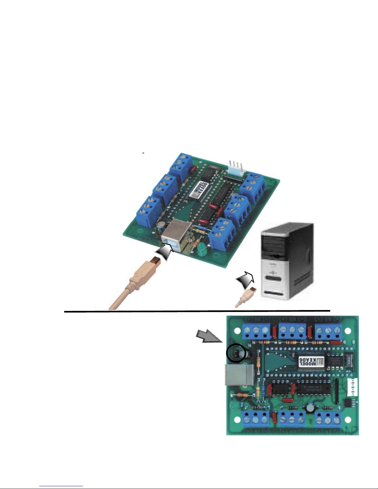
Computer Connections
There is one USB connector located on the KEAD6. Connection
to this port can be made with power on as the KEAD6 supports
“Hot Plug” operation as a USB device. When the KEAD6 is
plugged into a PC for the fi rst time, the appropriate standard
drivers are loaded by the operating system.
The KEAD6 emulates both a USB joystick and a standard USB
keyboard. The KEAD6 may be used in addition to or in place of
the system’s own keyboard.
2 23
Using the KEAD6 with Custom Software
In addition to converting potentiometer movement to keystrokes
or joystick action, the KEAD6 input channels can also be used
as an analog to digital converter. The current voltage level of
each channel can be read as an 8 bit value by the user’s custom
software utilizing the KEAD6.dll which is located on the included
CD-ROM.
A Visual Basic sample program demonstrating how to read
the digital values from the KEAD6 inputs is included on the
CD-ROM under the KEAD6_Sample folder. The source code for
this sample is also located under this folder.
*Note:
KEAD6 when used strictly as an analog to digital converter. To
disable the channels, use the KEAD6 confi guration utility.
Device ID Jumper
Two KEAD6 units may be connected to
the same computer and programmed
independently. If using one unit, leave
the Device ID jumper open (factory
default). If using two KEAD6 units,
leave the jumper open on unit 1 and
closed on unit 2. This setup will present
two different USB devices to the system
that both work as USB keyboards.
Page 5
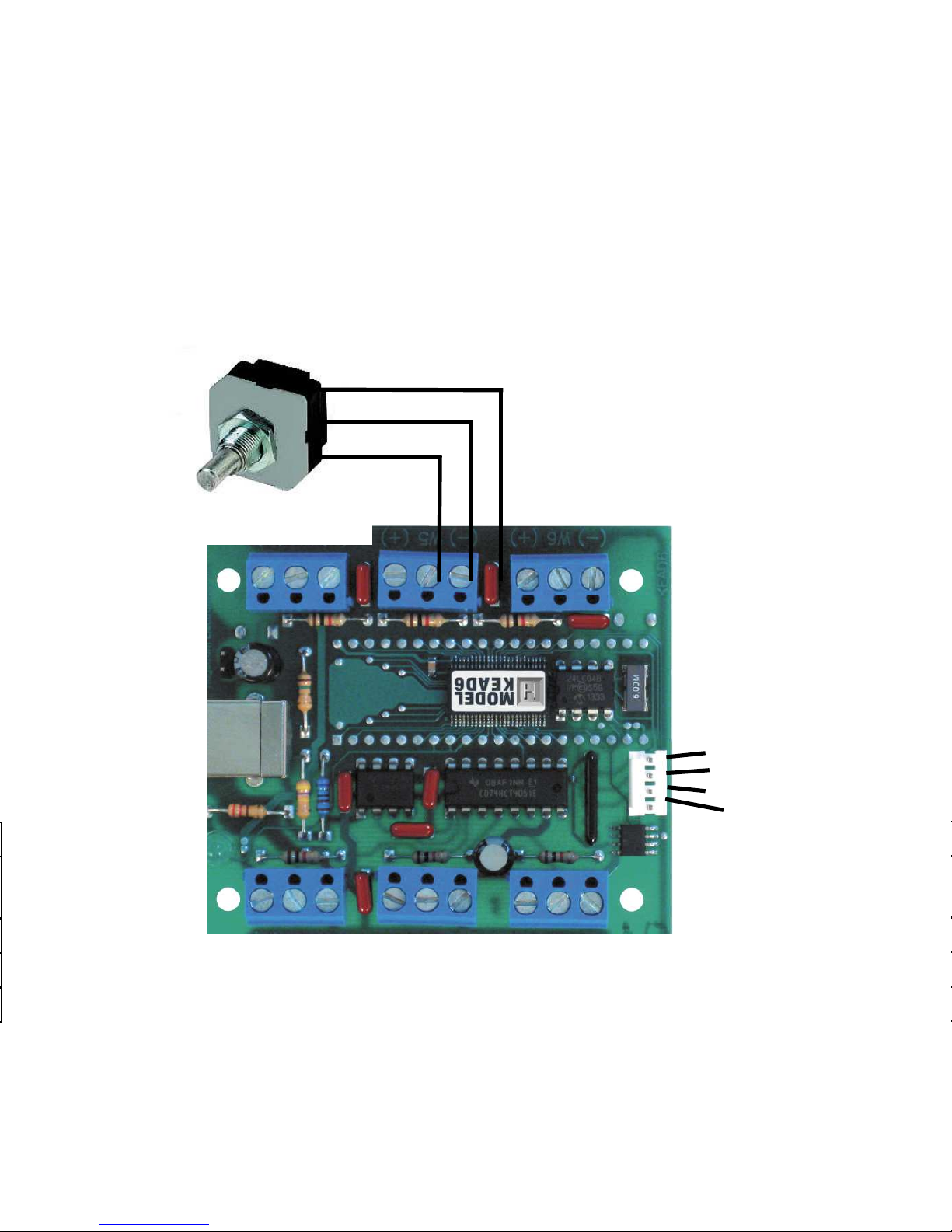
Interfacing to the KEAD6
The three-position screw terminal blocks on the KEAD6 are
used to connect potentiometers to the unit. The potentiometers
used with each KEAD6 input can range in value from 500Ω up
to 1MΩ. Potentiometers are connected to the +5V, Wiper input,
and Ground as shown below.
322
Wiper
+5V
Ground
Three Joystick Buttons
The four position header on the KEAD6 provides three inputs
and a logic ground signal. To activate an input, short it to the
provided logic ground through a switch. The activation of the
switch will create a joystick button press on the computer.
Button 3
Button 2
Button 1
Gnd
Page 6

The KEAD6.EXE Program
The KEAD6 unit is shipped with a CD-ROM containing the KEAD6.
EXE utility program which is used for confi guring the unit. The
confi guration program allows selection of whether the channel
is to emulate a joystick axis, keystrokes, or both. Additional
adjustable parameters include defi ning the number of response
steps per channel, the keystrokes generated by each step, and
other tuning options.
Getting Started
To use and confi gure the KEAD6, follow the steps listed below.
1. Attach the KEAD6 to the computer as described on
page 2 under the section “Computer Connections.”
2. Insert the CD and save the content to its own folder
on the hard drive. The CD may now be removed and
stored in a safe location for future use.
3. Open the folder that was created in step 2 and start
the confi guration program by selecting the program
fi le KEAD6.EXE.
*Note:
The programs must be copied to and run from its own
folder on the PC’s hard drive. The CD itself should be reserved
for backup purposes only.
4
*Note: When the KEAD6.EXE program is running, joystick
movement and keystrokes will no longer be produced by the
KEAD6 until the program is closed again. This disable mode
prevents any confl icts that may arise between the KEAD6
programmed responses and the confi guration program.
“Invalid confi guration”
“Invalid confi guration fi le”
When loading an already existing confi guration from a fi le or
uploading a confi guration from the KEAD6, the program will
give this error message if the fi le is corrupted or if it is the wrong
fi le type.
“Error opening the fi le”
This error message is shown if the KEAD6.EXE program attempts
to open a fi le that is already open in another application. If this
happens, close the other application and open the fi le again.
“Error saving fi le”
This error message is shown if the KEAD6.EXE program attempts
to save a fi le that is already open in another application, or if
there is not enough disk space. If this happens, close the other
application and try saving the fi le again.
“Error while writing to the KEAD6”
This indicates that, while the computer can communicate with
the KEAD6, it was not able to read or write the confi guration.
Communication may be interrupted if a user presses a key on
the keyboard or if another program takes the focus away from
the KEAD6 application. If this error message is displayed, load
the confi guration again.
Page 7
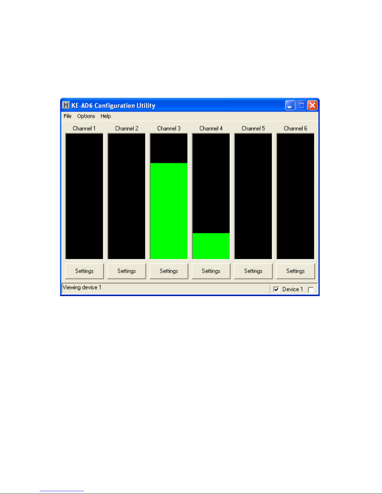
The Program Screen
The main program screen displays graphs of the current
positions of each of the six channels corresponding to the six
potentiometers on the KEAD6.
520
Switching Selected Device
If two KEAD6 units with properly assigned Device ID jumpers (see
page 2, section “Device ID Jumper“) are both connected to the
PC, then the KEAD6.EXE program must be set to which device
to monitor. In the lower right corner of the main screen there
are two checkboxes which are used to switch between Device
1 (left box) and Device 2 (right box). To change which device
is selected, click on the corresponding checkbox. An alternate
method is to select the Device ID under the Options menu.
If using a single KEAD6, the selection will be made automatically
by the program.
Page 8
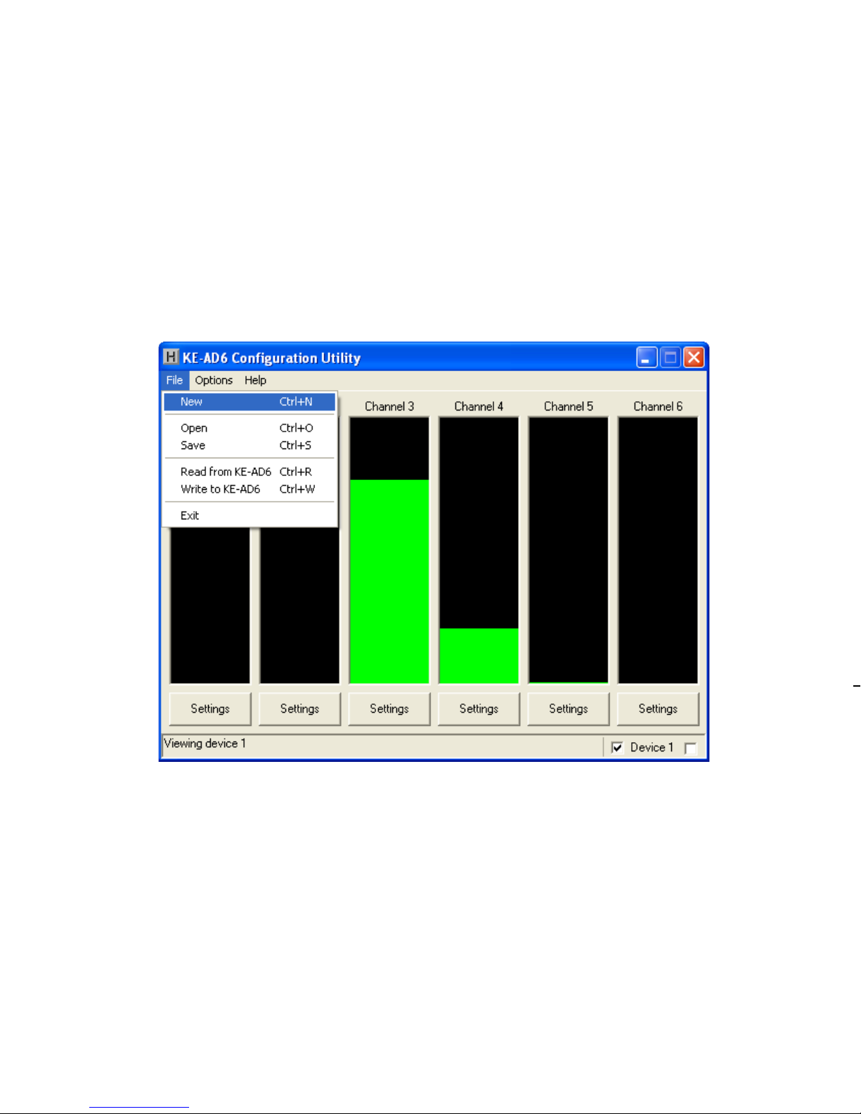
File Menu Selections
The fi le selections, located within a drop-down list, are accessed
by clicking on “File” in the upper left corner of the main program
screen. This list provides several options that include creating
and saving fi le confi gurations as well as reading and writing to
the KEAD6. A list of these options, along with descriptions of
how they pertain to the KEAD6 setup, are listed on the following
page.
Please check the following items before calling us.
• When connecting the KEAD6 to a PC, use a standard
USB A-B type Cable.
Saving a Confi guration to the KEAD6
To load the KEAD6 with the completed confi guration, click on
“Write to KEAD6” under the File menu. Be sure that the KEAD6
is connected to the PC. Once the KEAD6 is loaded and the
KEAD6.EXE program is closed, the KEAD6 will begin running the
new setup.
Once the desired confi guration is created, it should be saved to
disk. To do this click on “Save” under the File menu and specify
a fi le name under which to save the confi guration.
Page 9

718
New: Creates a new confi guration fi le by either clicking on
“New” with the mouse or by pressing Ctrl+N on the keyboard.
This option will also return the program screen to the default
settings.
Open: Recall a previously saved confi guration fi le by either
clicking on “Open” with the mouse or by pressing Ctrl+O on the
keyboard. Locate and select the name of the confi guration fi le
on the PC that is to be opened.
Save: Once a confi guration setup has been created on the
program screen, it is recommended that it be saved on the PC’s
hard disk. Click on “Save” with the mouse or press Ctrl+S on the
keyboard, then choose a location to save the fi le.
Read from KEAD6: This option will read the current
confi guration in the selected KEAD6 and display it on the screen.
Click on “Read from KEAD6” with the mouse or press Ctrl+R on
the keyboard to perform this operation.
Write to KEAD6: This option will write the current
confi guration displayed on the screen to the selected KEAD6.
The KEAD6 can be programmed and re-programmed as many
times as necessary. Click on “Write to KEAD6” with the mouse
or press Ctrl+W on the keyboard to perform this operation. After
the KEAD6 has been loaded with the new confi guration, it will
scan according to this new setup upon exit from the program.
Exit: This option exits and closes the KEAD6.EXE program.
*Note:
Make sure that the KEAD6 is connected to the PC before
performing either the “Read to KEAD6” or “Write to KEAD6”
operations. If the KEAD6 is not present, a “The KEAD6 was not
Found” error will be displayed on the computer screen.
Page 10

Options Menu Selections
Option parameters, located within a drop-down list, are accessed
by clicking on “Options” in the upper left corner of the main
program screen. A list of these options, along with descriptions
of how they pertain to the KEAD6 setup, are listed below.
Device 1: Click this option to select the device with an ID of 1.
See page 5, section “Switching Selected Device,” for details.
Device 2: Click this option to select the device with an ID of 2.
See page 5, section “Switching Selected Device,” for details.
Delay keystrokes at power on: This option determines
how long the KEAD6 waits upon being powered on before
beginning to send keystrokes. This can either be set to “Disabled”
or a value ranging from 1 second to 30 seconds. If this setting
is enabled, the KEAD6 will wait the selected time beginning at
power on before sending any programmed responses from the
input channels.
Any channels that are not used should be set to be disabled. To
disable a channel, fi rst open the settings window for the channel.
Then uncheck the Keyboard and Joystick “Enabled” checkboxes
(see arrows below). Once the confi guration is written to the
device, this channel will be disabled.
Page 11

Confi guring the KEAD6
Each input channel of the KEAD6 can be independently
confi gured. To edit the settings for a channel, click on the
“Settings” button below the graph of a channel. For example,
if changing channel 1 settings, the left most “Settings” button
must be selected. The settings window for channel 1 will then
appear as shown below (appearance may differ depending on
potentiometer setting and prior channel 1 settings selections) .
916
Page 12

10 15
Channel Settings Window
Each input has a number of different options which can be set
via the channel settings window. A list of these options along
with descriptions of how they pertain to the KEAD6 setup are
listed below.
Each step of the channel can be assigned a key which will be
emulated when the channel value reaches that step. To assign
keys, click on the desired step on the graph. A diagram of
the keyboard will be displayed, as shown below. Click on the
representation of the key to assign it to the selected step.
Keyboard Enabled Checkbox:
Checking this box enables the keyboard
section and activates programming of
number of steps, hysteresis, preload,
key repeat, and periodic keystrokes as
described below. If this box is unchecked, the keyboard section
is disabled. If using the input as a joystick axis only, leave this
box unchecked.
Number of steps: When the input
is programmed to send keystrokes,
each channel can be set into several
different modes listed below.
• Under step mode, the channel
becomes sectioned into a number of
equal parts, where each section can
be assigned a different keystroke. The
number of sections can be set to 2, 4,
8, 16, or 32.
• Under directional mode, t h e channel h as t wo different sections:
up and down. When the potentiometer is increasing in value, the
keystroke assigned to the up section is produced, and when the
potentiometer is decreasing in value, the keystroke assigned to
the down section is produced.
Hysteresis: This setting adjusts
the size of the overlap between
different sections. A keystroke will not
be produced until the channel value
reaches a certain distance past the
border. This distance can be set to low,
medium, or high. If the potentiometer
used is very precise, this setting
Page 13

can be set to low. If, however, the potentiometer produces an
unsteady reading, a setting of high should be used in order to
keep unintentional keystrokes from being produced.
Preload: With this option on, the
selected channel will not produce
any keystrokes upon power on until
the potentiometer for the channel
is moved. With this option off, the
channel will send out its current
position as soon as it is powered on
or, if set, after the power on delay.
Key repeat: With this option set to
off the keystrokes generated by this
channel will p r oduce o ne keystroke p er
step. In most cases this setting should
be set to off. Setting this option to on
causes the keystroke for the current
step to be held down as if a key on a
typical PC keyboard were being held. The rate at which the key
will repeat is the same as your PC keyboard settings on the PC.
Periodic keystrokes:
The channel can be set to produce a
keystroke corresponding to the current
position of the channel at a specifi ed
period of time. For example, if set to
5.0 sec., a keystroke corresponding
to the current position will be sent
out every 5 seconds. If, however, the
potentiometer position changes from
one section to another such that a
different keystroke is produced, the
periodic keystroke timer will be reset,
and another periodic keystroke will
Page 14

12 13
When programmed to send keystrokes, channels can be placed
into a step mode where the channel becomes sectioned into a
number of equal parts in which each section can be assigned
a different keystroke. To place a channel into step mode, fi rst
open the settings window for the channel. Make sure that the
keyboard enabled checkbox is checked. Change “Number of
steps” to 2, 4, 8, 16, or 32, as shown below. The keystrokes
these steps produce can be assigned by clicking on a section
of the graph and selecting a key representation as described in
the “Assigning Keystrokes” section found later in this manual.
When a channel has been set to step mode, the programmed
keystroke for that position is sent when the potentiometer value
crosses into that particular step from either direction.
not be sent out for another 5 seconds afterwards. The time
between the sending of each keystroke can be set between 0.1
seconds and 10.0 seconds. When set to disabled, no periodic
keystrokes are produced.
Joystick Enabled Checkbox:
Checking this box enables the joystick
section and activates programming of
joystick axis. If this box is unchecked
the joystick is disabled for this channel. The joystick should be
disabled for a given channel if it is not to emulate an axis.
Axis: Each channel can be set to one
of several different axes or controls as
listed below.
• X, Y or Z axis.
• Rx, Ry or Rz axis.
• Slider.
• Dial.
• Wheel.
• Vx, Vy or Vz axis.
• Vbrx, Vbry or Vbrz.
• Vno.
To make a selection, open the drop down list by clicking on the
down arrow next to the current selection and click on the new
choice of axis or control. A particular axis from the list may
only be used in one channel and will not appear in the list if it is
used in another channel. For example if in channel 1 settings
the joystick is enabled and the X axis is selected then the X axis
selection will not be available in the axis
drop down list in the other channels.
When a joystick axis or control is chosen, the
selection will be displayed in yellow text in
the middle of the channel settings window.
For example if the X axis is selected the
following will be displayed.
Page 15

Step Mode
When programmed to send keystrokes, channels can be placed
into a step mode where the channel becomes sectioned into a
number of equal parts in which each section can be assigned
a different keystroke. To place a channel into step mode, fi rst
open the settings window for the channel. Make sure that the
keyboard enabled checkbox is checked. Change “Number of
steps” to 2, 4, 8, 16, or 32, as shown below. The keystrokes
these steps produce can be assigned by clicking on a section
of the graph and selecting a key representation as described in
the “Assigning Keystrokes” section found later in this manual.
When a channel has been set to step mode, the programmed
keystroke for that position is sent when the potentiometer value
crosses into that particular step from either direction.
Page 16

14 11
Directional Mode
When sending keystrokes, channels may be placed into a
directional mode where the keystrokes are produced when
the channel value changes by a defi ned amount. The amount
of potentiometer movement required to generate a keystroke
in this mode is determined by the hysteresis setting. To place
a channel into directional mode, open the settings window for
the channel. Then change “Number of steps” to Directional as
shown below. The graph will show two arrows which represent
increasing and decreasing values. The keystrokes produced
can be assigned by clicking on an arrow and selecting a key
representation as described on the following page.
can be set to low. If, however, the potentiometer produces an
unsteady reading, a setting of high should be used in order to
keep unintentional keystrokes from being produced.
Preload: With this option on, the
selected channel will not produce
any keystrokes upon power on until
the potentiometer for the channel
is moved. With this option off, the
channel will send out its current
position as soon as it is powered on
or, if set, after the power on delay.
Key repeat: With this option set to
off the keystrokes generated by this
channel will p r oduce o ne keystroke p er
step. In most cases this setting should
be set to off. Setting this option to on
causes the keystroke for the current
step to be held down as if a key on a
typical PC keyboard were being held. The rate at which the key
will repeat is the same as your PC keyboard settings on the PC.
Periodic keystrokes:
The channel can be set to produce a
keystroke corresponding to the current
position of the channel at a specifi ed
period of time. For example, if set to
5.0 sec., a keystroke corresponding
to the current position will be sent
out every 5 seconds. If, however, the
potentiometer position changes from
one section to another such that a
different keystroke is produced, the
periodic keystroke timer will be reset,
and another periodic keystroke will
Page 17

Each step of the channel can be assigned a key which will be
emulated when the channel value reaches that step. To assign
keys, click on the desired step on the graph. A diagram of
the keyboard will be displayed, as shown below. Click on the
representation of the key to assign it to the selected step.
Assigning Keystrokes
Page 18

Each input channel of the KEAD6 can be independently
confi gured. To edit the settings for a channel, click on the
“Settings” button below the graph of a channel. For example,
if changing channel 1 settings, the left most “Settings” button
must be selected. The settings window for channel 1 will then
appear as shown below (appearance may differ depending on
potentiometer setting and prior channel 1 settings selections) .
The KEAD6 has the capability to assign Shift, Ctrl, and Alt
functions along with a keystroke. For example, one of the
responses could be defi ned as the Ctrl+Alt+Del sequence. The
keystrokes emulated by this combination have the same effect
as holding the control and alt keys, then pressing the delete key
on a PC keyboard. To create this input, check the Ctrl and Alt
boxes on the lower left corner of the keyboard diagram, then
click the Del button (shown below).
Any step in the channel can be modifi ed by one or a combination
of Shift, Alt, or Ctrl keys using the method described above. Use
the Shift function to generate uppercase characters or shifted
characters (!, @, etc.) in the application. Combinations such as
Ctrl+Alt+F1 can also be created by checking the appropriate
boxes along with the selected key. To remove one of these
special functions, uncheck the appropriate box and click on the
desired key.
Page 19

178
Disabling Channels
Any channels that are not used should be set to be disabled. To
disable a channel, fi rst open the settings window for the channel.
Then uncheck the Keyboard and Joystick “Enabled” checkboxes
(see arrows below). Once the confi guration is written to the
device, this channel will be disabled.
Page 20

New: Creates a new confi guration fi le by either clicking on
“New” with the mouse or by pressing Ctrl+N on the keyboard.
This option will also return the program screen to the default
settings.
Open: Recall a previously saved confi guration fi le by either
clicking on “Open” with the mouse or by pressing Ctrl+O on the
keyboard. Locate and select the name of the confi guration fi le
on the PC that is to be opened.
Save: Once a confi guration setup has been created on the
program screen, it is recommended that it be saved on the PC’s
hard disk. Click on “Save” with the mouse or press Ctrl+S on the
keyboard, then choose a location to save the fi le.
Read from KEAD6: This option will read the current
confi guration in the selected KEAD6 and display it on the screen.
Click on “Read from KEAD6” with the mouse or press Ctrl+R on
the keyboard to perform this operation.
Write to KEAD6: This option will write the current
confi guration displayed on the screen to the selected KEAD6.
The KEAD6 can be programmed and re-programmed as many
times as necessary. Click on “Write to KEAD6” with the mouse
or press Ctrl+W on the keyboard to perform this operation. After
the KEAD6 has been loaded with the new confi guration, it will
scan according to this new setup upon exit from the program.
Exit: This option exits and closes the KEAD6.EXE program.
*Note:
performing either the “Read to KEAD6” or “Write to KEAD6”
operations. If the KEAD6 is not present, a “The KEAD6 was not
Found” error will be displayed on the computer screen.
Accepting Changes
To accept the changes made to a channel setup, click the OK
button as shown below. To discard any changes made to the
channel settings, click the Cancel button.
*Note:
No changes will take place on the KEAD6 itself until
the confi guration has been written to the device. Refer to the
following page for details on how to write to the KEAD6.
Page 21

196
KEAD6 Operating Tips
Please check the following items before calling us.
• When connecting the KEAD6 to a PC, use a standard
USB A-B type Cable.
Saving a Confi guration to the KEAD6
To load the KEAD6 with the completed confi guration, click on
“Write to KEAD6” under the File menu. Be sure that the KEAD6
is connected to the PC. Once the KEAD6 is loaded and the
KEAD6.EXE program is closed, the KEAD6 will begin running the
new setup.
Saving to Disk
Once the desired confi guration is created, it should be saved to
disk. To do this click on “Save” under the File menu and specify
a fi le name under which to save the confi guration.
Page 22

The main program screen displays graphs of the current
positions of each of the six channels corresponding to the six
potentiometers on the KEAD6.
If two KEAD6 units with properly assigned Device ID jumpers (see
page 2, section “Device ID Jumper“) are both connected to the
PC, then the KEAD6.EXE program must be set to which device
to monitor. In the lower right corner of the main screen there
are two checkboxes which are used to switch between Device
1 (left box) and Device 2 (right box). To change which device
is selected, click on the corresponding checkbox. An alternate
method is to select the Device ID under the Options menu.
If using a single KEAD6, the selection will be made automatically
by the program.
• The KEAD6.EXE program must be closed before the
KEAD6 will p roduce any keystrokes or joystick movement.
The KEAD6.EXE program temporarily disables the KEAD6
responses in order to prevent potential confl icts when
changing confi gurations.
• The maximum recommended cable length from the
computer to the KEAD6 is 10 feet. This distance is also
the maximum length that should be used on connections
from any potentiometer to the KEAD6 input channels.
• If using a Device ID jumper, only make changes to it
when the power to the unit is off as the jumper state is
sampled at power on or reset only.
• Before using the KEAD6.EXE program, visit Microsoft
“Windows Update” and get the latest updates for the
operating system. This step is important for making sure
the PC has the latest USB port updates.
*Note:
For any questions that are not answered in this
manual, please send us an email or call customer service. We
have customer service available from 8:00 am to 5:00 pm (EST)
Monday through Friday.
customer service email: sales@hagstromelectronics.com
Toll Free 888-690-9080, or (540) 465-4677
Error Messages
“The KEAD6 was not found”
This error occurs if the computer cannot communicate with
the KEAD6 when trying to save to the KEAD6 or read from the
KEAD6. Check the cable connections to make sure none of them
are loose or unplugged.
“Error while reading from the KEAD6”
Page 23

21
“Invalid confi guration”
“Invalid confi guration fi le”
When loading an already existing confi guration from a fi le or
uploading a confi guration from the KEAD6, the program will
give this error message if the fi le is corrupted or if it is the wrong
fi le type.
“Error opening the fi le”
This error message is shown if the KEAD6.EXE program attempts
to open a fi le that is already open in another application. If this
happens, close the other application and open the fi le again.
“Error saving fi le”
This error message is shown if the KEAD6.EXE program attempts
to save a fi le that is already open in another application, or if
there is not enough disk space. If this happens, close the other
application and try saving the fi le again.
“Error while writing to the KEAD6”
This indicates that, while the computer can communicate with
the KEAD6, it was not able to read or write the confi guration.
Communication may be interrupted if a user presses a key on
the keyboard or if another program takes the focus away from
the KEAD6 application. If this error message is displayed, load
the confi guration again.
Page 24

The three-position screw terminal blocks on the KEAD6 are
used to connect potentiometers to the unit. The potentiometers
used with each KEAD6 input can range in value from 500Ω up
to 1MΩ. Potentiometers are connected to the +5V, Wiper input,
and Ground as shown below.
Operating Voltage
5 Volts DC +/- 5%
Operating Current
15 ma Typical
+ potentiometers
Operating Temp.
0 to 70 Degrees C
PC Interface
USB
Potentiometer Range
500Ω to 1MΩ
Appendix A:
KEAD6 Specifi cations
2.7”
3.0”
.125”
Dia. (4)
The four position header on the KEAD6 provides three inputs
and a logic ground signal. To activate an input, short it to the
provided logic ground through a switch. The activation of the
switch will create a joystick button press on the computer.
Page 25

Appendix B:
Using the KEAD6 with Custom Software
In addition to converting potentiometer movement to keystrokes
or joystick action, the KEAD6 input channels can also be used
as an analog to digital converter. The current voltage level of
each channel can be read as an 8 bit value by the user’s custom
software utilizing the KEAD6.dll which is located on the included
CD-ROM.
A Visual Basic sample program demonstrating how to read
the digital values from the KEAD6 inputs is included on the
CD-ROM under the KEAD6_Sample folder. The source code for
this sample is also located under this folder.
*Note:
We recommend disabling all scanned channels on the
KEAD6 when used strictly as an analog to digital converter. To
disable the channels, use the KEAD6 confi guration utility.
Page 26

Our KEAD6 Interface is a product designed to interface potentiometers
to the computer’s USB port. Potentiometers connected to the KEAD6
input channels produce joystick axis movement and/or keystrokes on
the PC.
The KEAD6 is fully programmable by the user. This programmability
feature allows the confi guration of each input channel according to the
joystick axis and/or keystrokes to be emulated by the potentiometer
connected to that particular input. Each input of the KEAD6 may be
programmed to emulate a joystick axis, send keystrokes based on
the potentiometer movement, or both joystick and keystrokes from a
single channel. The KEAD6 stores the user’s confi guration program in
non-volatile memory so that the confi guration information is retained
on the unit even after power is turned off. The KEAD6 confi guration
may be changed using the included software as many times as
required for various applications.
The KEAD6 Input Channels
The KEAD6 features six input channels with screw terminals to easily
connect potentiometers. Three Joystick Buttons are also provided.
Power Requirements
The KEAD6 requires no external power source. It is powered directly
from the USB port on the PC.
Supported Computers
All PCs with a standard USB port will work with the KEAD6. The
KEAD6.EXE confi guration program is for Windows based systems.
Hardware Requirements
The KEAD6 is designed to work with standard, commercially available
cables for connection to the PC. A standard A-B Type USB cable is
required for this connection.
Default Settings
The KEAD6 is programmed and shipped with a default confi guration
with keystrokes from all channels disabled.
24
Accessories
KE-USBMM6
6 foot USB Type A to Type B connecting
cable between KEAD6 and PC.
MTA100-4-12
Cable set for use with KEAD6 Joystick Button inputs, 4 wires, each 12 inches long.
Te rminated with a 4 position connector on
one end with loose wires at the other end.
Page 27

Warranty
HAGSTROM ELECTRONICS, INC. warrants this
product against defects in material or workmanship for a
period of ONE YEAR from the original purchase date. We will
repair or replace (at our option) the returned defective unit
at no charge during this warranty period.
No responsibility is assumed for any special, incidental,
or consequential damage resulting from the use of or
inability to use this product. In no case is HAGSTROM
ELECTRONICS, INC. to be liable for any amount which
exceeds the purchase price of the unit, regardless of the
claim.
No other warranty, written or verbal, is authorized. This
warranty is applicable only to units sold in the United States.
Units sold outside the United States are covered by a similar
warranty.
Depending on the state in which you live, you may have additional rights.
Great care has been taken during the assembly, testing, and burn-in
of your KEAD6 to ensure its performance. If you have any questions,
please send us an email or give us a call. Support is available Monday
through Friday, 8:00 am to 5:00 pm (EST).
customer service email: sales@hagstromelectronics.com
Call Toll Free 888-690-9080, or (540) 465-4677
NOTICE The KEAD6 product is designed to be used by technically
oriented computer users. When the KEAD6 is in use, your computer’s
signals and voltages are present on the unit. Prudent handling and
packaging is necessary to prevent damage to your computer.
Your keyboard encoder is designed for OEM use, and is not FCC part 15 approved. Because
the packaging and use of the product will directly affect the characteristics of the unit, it is the
responsibility of the purchaser to obtain fi nal approval of their application, if required.
Page 28

Toll Free 888-690-9080
Phone: (540) 465-4677 Fax: (540) 465-4678
Monday through Friday, 8:00 am to 5:00 pm (EST)
sales@hagstromelectronics.com
www.hagstromelectronics.com
1986 Junction Road, Strasburg, VA 22657
Copyright © 2017 HAGSTROM ELECTRONICS, INC.
V. 07.16
HAGSTROM
ELECTRONICS, INC.
 Loading...