

Page 1

KE24
PC Keyboard Encoder
User Manual
Page 2

HAGSTROM ELECTRONICS, INC. warrants this
product against defects in material or workmanship for a
period of ONE YEAR from the original purchase date. We will
repair or replace (at our option) the returned defective unit
at no charge during this warranty period.
No responsibility is assumed for any special, incidental,
or consequential damage resulting from the use of or
inability to use this product. In no case is HAGSTROM
ELECTRONICS, INC. to be liable for any amount which
exceeds the purchase price of the unit, regardless of the
claim.
No other warranty, written or verbal, is authorized. This
warranty is applicable only to units sold in the United States.
Units sold outside the United States are covered by a similar
warranty.
Depending on the state in which you live, you may have additional rights.
Great care has been taken during the assembly, testing, and burn-in
of your KE24 to ensure its performance. If you have any questions,
please send us an email or give us a call. Support is available Monday
through Friday, 8:00 am to 5:00 pm (EST).
customer service email: sales@hagstromelectronics.com
Call Toll Free 888-690-9080, or (540) 465-4677
NOTICE: The KE24 product is designed to be used by technically
oriented computer users. When the KE24 is in use, your computer’s
signals and voltages are present on the unit. Prudent handling and
packaging is necessary to prevent damage to your computer.
Your keyboard encoder is designed for OEM use, and is not FCC part 15 approved. Because
the packaging and use of the product will directly affect the characteristics of the unit, it is the
responsibility of the purchaser to obtain final approval of their application, if required.
PS/2 is a Trademark of International Business Machines.
Thank you for purchasing the model KE24 Keyboard Encoder.
HAGSTROM ELECTRONICS, INC.
is pleased that you have selected this product for your application.
The KE24 unit is configurable in a variety of ways in order to
meet your specific requirements. Please take a few minutes to
read this manual before using your KE24.
In addition to this printed manual, other resources are included
with the product CD which provide information and tips on using
the KE24 and making the most of it’s features.
If you have any questions about the use of the KE24 not covered
in this manual, please contact us directly. We offer toll free
technical product support from 8:00am to 5:00pm M-F Eastern
Time 888-690-9080. You may also send an email to
sales@hagstromelectronics.com
We respond to all email requests within one business day.
Page 3

CONTENTS
Introduction to the KE24
Interfacing to the KE24 I/O Header
Connection to Computer and Keyboard
Serial Data to PC Keyboard Input
PC Keyboard to Serial Port
KE24 I/O Data to Serial Port
The KE24Load Program
Programming Macros
Appendix A - Specifications
Appendix B - Connection of an External Supply
Appendix C - Placing KE24 into PROGRAM Mode
Appendix D - KE24 Operating Tips
Accessories
2
3
5
6
8
11
12
13
21
25
26
27
28
29
Page 4

Appendix D:
KE24 Operating Tips
In the event that you are experiencing difficulty in using your KE24,
please check the following items before calling us:
•When connecting the KE24 to a PC and keyboard, make sure they
are plugged into the proper ports. The connector marked “To PC”
on the KE24 must be connected to the PC keyboard input. Attach
your computer keyboard to the KE24 connector marked “KBD.” The
KE24 will not function properly if these connections are reversed.
•Check your KE24 configuration. Be sure to select the type of
computer that you are using (XT or AT compatible). Check your I/O
configuration for the number of columns and rows, etc. Review your
matrix or discrete input table for the desired responses.
•If you are having trouble getting your PC keyboard to work with the
KE24, make sure that the keyboard itself is configured for the type
of computer you have specified in the configuration (XT or AT
compatible).
•The maximum recommended cable length from your computer to the
KE24 is 10 feet. This distance is also the maximum length that you
should use on connections from the switches or keypads in your
applications to the KE24 I/O header.
•If your KE24 will not communicate with the KE24Load program,
check the COM port selection. Also be sure to power up the KE24
with the programming jumper in place. Refer to page 12 for more
information on programming the KE24 unit.
•If you cannot get the KE24 to respond to your configuration, make
sure that you have removed the programming jumper and powered
the unit back up without the jumper in place.
If you have any questions that are not answered in this manual,
please give us a call. We have customer service available from
8:00 am to 5:00 p.m. (Eastern) Monday through Friday.
Introduction to the KE24
The KE24 Keyboard Encoder is a product designed to interface
keypads, switches, or RS-232 to your computer’s keyboard input.
Additionally, the RS-232 serial communication port may be used
in a variety of other ways to create the type of interface that you
require.
The KE24 is user programmable. This feature allows you to
configure the I/O and select the operating modes for the unit.
Nonvolatile memory stores your configuration information.
The KE24 I/O:
The 52 pin header in the KE24 provides 24 I/O signals that can
be programmed to scan a matrix or discrete inputs. Any of the 24
I/O pins can be programmed as a Row or Column in a matrix
application, or as an individual input. A matrix size from 1x1 to
12x12 can be scanned. I/O pins not assigned as Rows or Columns
in a matrix application may be used as discrete inputs. Input from
the I/O header may be directed to the PC keyboard input, or to
the KE24 RS-232 port.
Modes of KE24 operation:
These modes may be used individually or combined with other
modes of operation.
3
Input Output
RS-232 PC Keyboard Input
Keypads or Switches PC Keyboard Input
Keypads or Switches RS-232 Port
PC Keyboard PC Keyboard Input
PC Keyboard RS-232 Port
Page 5

Power:
In applications where the KE24 is attached to the computer’s
keyboard input, the KE24 gets its power from the computer. If
used in other modes, an external 5V power supply is required.
See Appendix B for information on connecting an external 5V
supply.
Supported Computers:
The KE24 may be used with PCXT, AT, PS/2, 286, 386, 486,
Pentium, and compatibles.
Hardware Required:
For programming the KE24 configuration only. A serial port
(COM1 through COM6) on your PC, and a DB9 serial cable
(Male to Female).
Default Settings:
4
PC Type:
AT
Serial Port:
Disabled
I/O Header:
Configured as 24 Discrete Inputs.
(Connect the input to ground to activate it. Codes directed to the PC
keyboard input. Pin “A” emulates
the “A” key, input “B” emulates the
“B” key, etc.)
External Keyboard:
Directed to the PC keyboard input.
Page 6
Appendix B:
Connection of an External 5 Volt Supply
When using the KE24 in an application that does not require
connection to a PC (such as an RS-232 keypad interface), an
external 5 volt power supply must be used. The KE24 has a
connection point that is dedicated for this purpose.
Two solder points are supplied for attaching external wires or a
connector to the KE24 to supply the 5 volts.
Special care must be taken to assure the proper polarity of the
voltage. The supply must be within 4.75 to 5.25 volts DC.
Note: Reverse connection of the supply voltage will permanently
damage the unit. Use 5 volt source only. Do not attempt this
connection if you are uncertain of your power supply voltage or
polarity.
NEVER attach a KE24 that is powered from an external source
to a PC, as this may damage the KE24, the computer, and/or your
supply.
Ground
Connection
+5 Volt
Connection
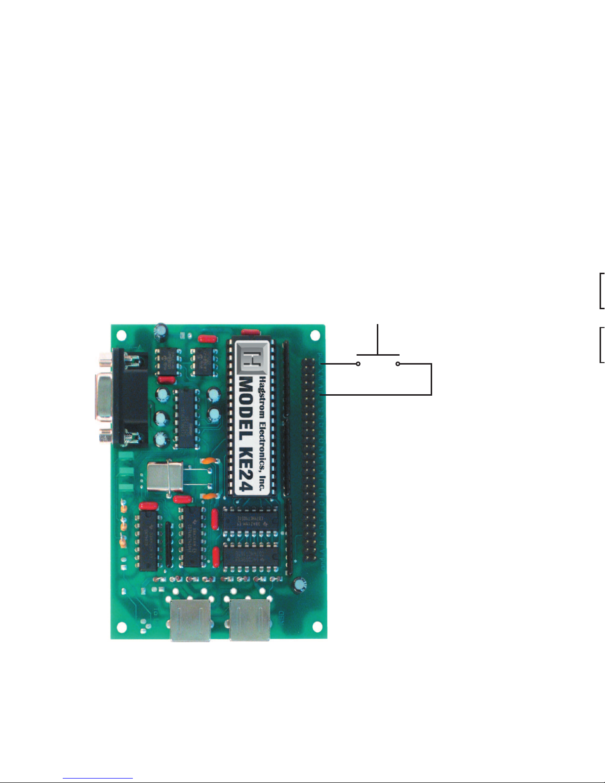
Interfacing to the KE24 I/O Header
The 52 pin header on the KE24 consists of 24 I/O points with
ground connections on either end. Each pin of the dual row
header is connected in parallel with its adjacent pin. Therefore,
each I/O signal is available on two different pins.
Each of the 24 I/O pins may be configured by the KE24Load
program. Pins may be independently configured to be either Rows
or Columns in a matrix scanning application, or discrete inputs.
Activation of an input in a matrix mode requires that a row and
column be shorted together to produce a keystroke. Discrete
inputs are activated by shorting the desired input to the ground
signal located on either end of the dual row header.
Figure 1.1 demonstrates how to activate an input that has been
programmed to be a discrete input. Although a switch is shown in
this diagram, other devices may be used in this mode to
5
Figure 1.1
Inputs used in discrete mode
must be shorted to ground to
activate them. Switches, keypads, or other electronic devices that “sink” at least 1 ma
of current may be used.
Page 7
activate the input. Devices such as open collector drivers or any
device capable of sinking at least 1 ma can be used to drive
discrete inputs. Never connect any signals that exceed the 5 Volt
operational voltage of the KE24.
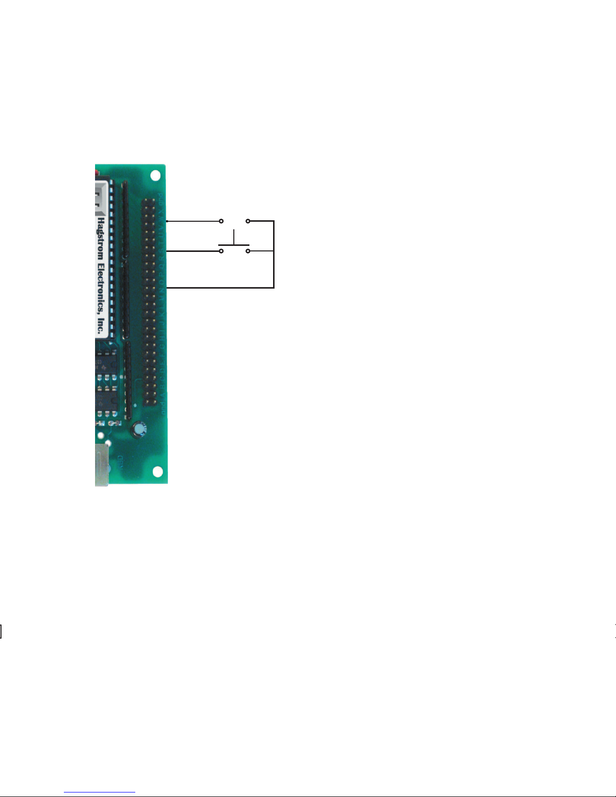
Figure 1.2 is an example of connecting an input to the KE24
when the I/O pins have been
configured for matrix operation.
One I/O pin defined as column
is shorted to one I/O pin
defined as a row. In this mode,
the switch or input device must
be capable of carrying at least
1 ma. Typically, the device used
for activating inputs in this mode
are keypads or switches, but
other electronic circuits may
be used, provided they do not
exceed the 5 volt range of the
KE24 I/O. Pins defined as Rows
in this mode sink current while
scanning, and the Columns are
used to read the status of the
inputs when a column is active.
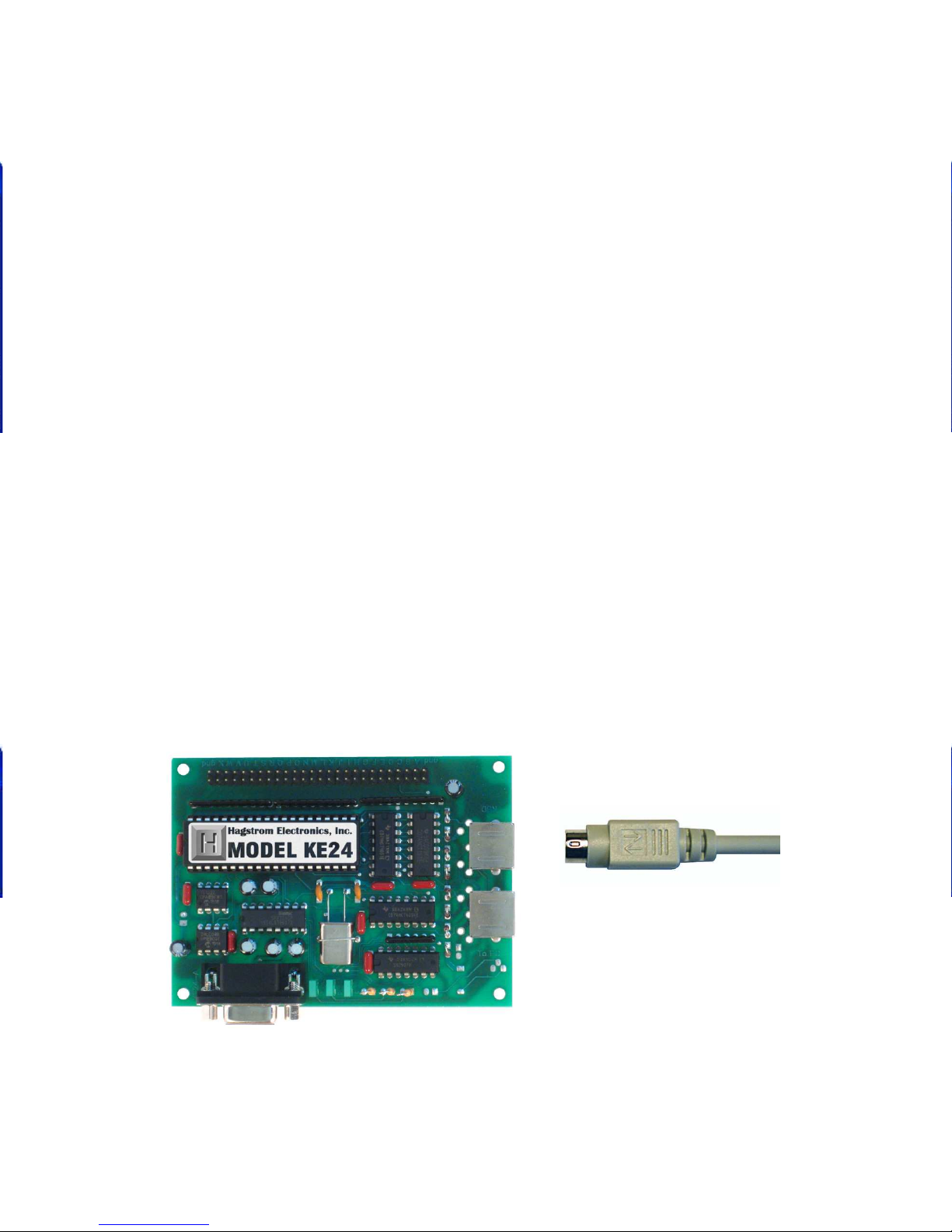
There are two DIN type connectors located on your KE24. Although
the connectors are physically alike, they have different functions.
The connector marked “To PC” is for interface of the KE24 to the
computer’s keyboard input. Insert one end of the 5 pin DIN (male
to male) shielded cable into this port. Connect the other end of
the cable into your computer’s keyboard input. Always perform
this connection with the computer’s power off.
The connector marked “KBD” is for using an external keyboard
6
Figure 1.2
In matrix mode,
inputs are activated by shorting a pin defined
as a row to a pin
defined as a column.
Column
Column
Row
(open)
(closed)
Page 8

The lower right corner of
the screen displays the
amount of Macro memory
available. Each keystroke
occupies one position in
the Macro memory. When
the Macro memory is full,
you may not create any
more Macros.
Below is an example of a completed matrix and set of inputs.
with the KE24. Plug the end of your keyboard cable into this port
to use it in addition to the
KE24. Use of the external
keyboard is optional, you
do not need to have a
keyboard plugged into
this port for the KE24 to
operate.
Since the KE24 supplies
the computer with all the
appropriate keyboard
signals, you may operate with just the KE24 attached to the
computer, or both the KE24 and an external keyboard.
Use of the external keyboard is usually beneficial when developing
KE24 applications.
Note: If you plug the computer into the incorrect port on the
KE24, you will receive an error message on your computer. If this
happens, turn off the computer and correct the connection.
The serial port on your KE24 may be used for input and output in
several different modes.
• Data received may be sent to the computer’s keyboard input.
• Keypads and switches connected to the KE24 I/O header may
be programmed to produce serial output codes (codes defined
by the user).
• Keystrokes from an external PC keyboard can be directed to the
serial port instead of the computer.
The serial port uses an 8 bit, no parity, 1 stop bit protocol. The
Baud rate is programmable through the KE24Load program.
7
From External Keyboard
To Computer Keyboard
Input
(Optional)
Page 9
Serial Data to PC Keyboard Input
When serial information is received on the KE24 RS-232 port, it
may be translated in one of two user selectable manners.
One method allows for receiving ASCII characters on the serial
port. Characters are translated into PC keyboard signals and sent
directly to the computer. Although this method provides a simple
interface, it does not allow for full keyboard functions, or multiple
keystroke commands such as Ctr/Alt, etc.
The second method receives codes from 1 to 127, which each
correspond to a key on the PC keyboard. The KE24 translates these
codes into PC keyboard signals. In addition, each code sent has
a “make” and a “break” value for the key. Reception of a “make”
code on the serial port produces a signal into the computer that
is the equivalent of pressing that key on a keyboard and holding
it down (without repeat). In order to simulate the release of that
key, you must send a “break” code for the same key. Several
“make” codes can be transmitted before their corresponding
“break” codes, which allows for emulation of key sequences such
as Shift+F1, Ctrl+L, etc.
8
Connecting the KE24 to a PC
Page 10
to assign a key using the keyboard representation, as shown
below.
The Macro dialog has two areas, the
MAKE section and the BREAK section.
The MAKE section contains the keystrokes
that you want to KE24 to send when the
input becomes active. The BREAK section
contains the keystrokes to be sent when
that input is released. Although keys in the
MAKE and BREAK sections default to
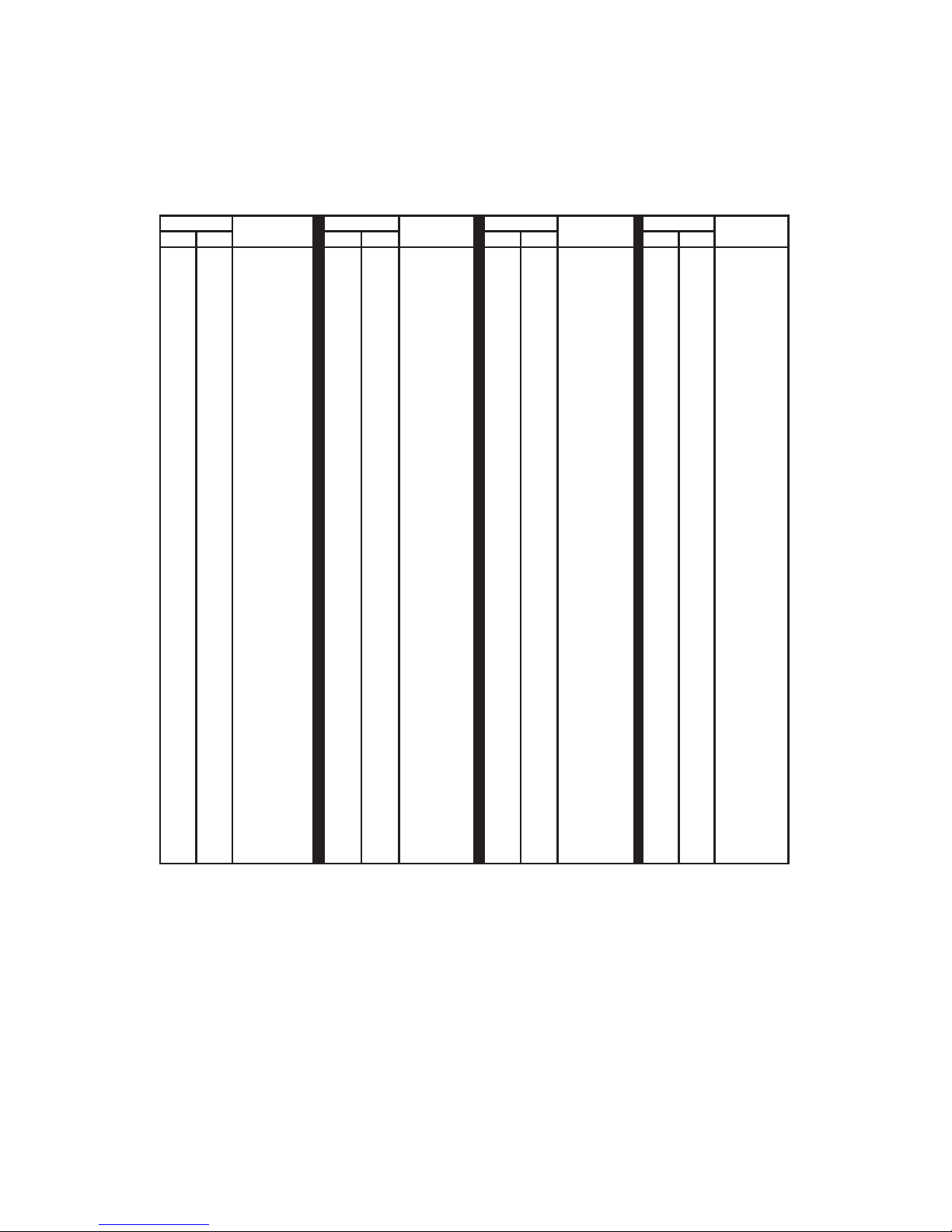
When programmed to receive ASCII characters on the serial port,
these are the codes allowed and the keystrokes emulated by that
particular code.
ASCII Translation Table
When a code has been sent to the KE24 serial port, the sending
unit must wait for a response from the KE24 before transmission
of the next code. This acknowledge response is a “!” character
transmitted by the KE24. Once this response has been received,
the next code may be sent to the KE24 serial port.
9
Value
Character
Value
Character
Value
Character
Value
Character
Dec Hex Dec Hex Dec Hex Dec Hex
00
01
02
03
04
05
06
07
08
09
10
11
12
13
14
15
16
17
18
19
20
21
22
23
24
25
26
27
28
29
30
31
00
01
02
03
04
05
06
07
08
09
0A
0B
0C
0D
0E
0F
10
11
12
13
14
15
16
17
18
19
1A
1B
1C
1D
1E
1F
none
none
none
none
none
none
none
none
Backspace
Tab
none
none
none
Return
F11
F12
none
F1
F2
F3
F4
F5
F6
F7
F8
F9
F10
Esc
none
none
none
none
32
33
34
35
36
37
38
39
40
41
42
43
44
45
46
47
48
49
50
51
52
53
54
55
56
57
58
59
60
61
62
63
20
21
22
23
24
25
26
27
28
29
2A
2B
2C
2D
2E
2F
30
31
32
33
34
35
36
37
38
39
3A
3B
3C
3D
3E
3F
Space
!
“
#
$
%
&
‘
(
)
*
+
,
_
.
/
0
1
2
3
4
5
6
7
8
9
:
;
<
=
>
?
64
65
66
67
68
69
70
71
72
73
74
75
76
77
78
79
80
81
82
83
84
85
86
87
88
89
90
91
92
93
94
95
40
41
42
43
44
45
46
47
48
49
4A
4B
4C
4D
4E
4F
50
51
52
53
54
55
56
57
58
59
5A
5B
5C
5D
5E
5F
@
A
B
C
D
E
F
G
H
I
J
K
L
M
N
O
P
Q
R
S
T
U
V
W
X
Y
Z
[
\
]
^
-
96
97
98
99
100
101
102
103
104
105
106
107
108
109
110
111
112
113
114
115
116
117
118
119
120
121
122
123
124
125
126
127
60
61
62
63
64
65
66
67
68
69
6A
6B
6C
6D
6E
6F
70
71
72
73
74
75
76
77
78
79
7A
7B
7C
7D
7E
7F
`
a
b
c
d
e
f
g
h
i
j
k
l
m
n
o
p
q
r
s
t
u
v
w
x
y
z
{
|
}
~
none
Page 11

When programmed to receive key numbers on the serial port,
these are the keys emulated for that key number.
Key Number Translation Table
As in the ASCII mode, the sending unit must wait for a response from
the KE24 after the transmission of each code. This acknowledge
response is a “!” character transmitted by the KE24 and signifies
that the KE24 can receive more data.
10
Character Make Break Character Make Break Character Make Break
~`
1 !
2 @
3 #
4 $
5 %
6 ^
7 &
8 *
9 (
0 )
- _
+ =
Backspace
Tab
Q
W
E
R
T
Y
U
I
O
P
[ {
] }
| \
Caps
A
S
D
F
01
02
03
04
05
06
07
08
09
10
11
12
13
15
16
17
18
19
20
21
22
23
24
25
26
27
28
29
30
31
32
33
34
129
130
131
132
133
134
135
136
137
138
139
140
141
143
144
145
146
147
148
149
150
151
152
153
154
155
156
157
158
159
160
161
162
G
H
J
K
L
; :
‘ “
Enter
L Shift
Z
X
C
V
B
N
M
, <
> .
/ ?
R Shift
L Ctrl
L Alt
Space
R Alt
R Ctrl
Insert
Delete
L Arrow
Home
End
Up Arrow
Dn Arrow
Pg Up
35
36
37
38
39
40
41
43
44
46
47
48
49
50
51
52
53
54
55
57
58
60
61
62
64
75
76
79
80
81
83
84
85
163
164
165
166
167
168
169
171
172
174
175
176
177
178
179
180
181
182
183
185
186
188
189
190
192
203
204
207
208
209
211
212
213
Pg Dn
R Arrow
Num Lk
7 (Num)
4 (Num)
1 (Num)
/ (Num)
8 (Num)
5 (Num)
2 (Num)
0 (Num)
* (Num)
9 (Num)
6 (Num)
3 (Num)
. (Num)
- (Num)
+ (Num)
Enter (Num)
Esc
F1
F2
F3
F4
F5
F6
F7
F8
F9
F10
F11
F12
Prt Scrn
86
89
90
91
92
93
95
96
97
98
99
100
101
102
103
104
105
106
108
110
112
113
114
115
116
117
118
119
120
121
122
123
124
214
217
218
219
220
221
223
224
225
226
227
228
229
230
231
232
233
234
236
238
240
241
242
243
244
245
246
247
248
249
250
251
252
Note: The pause key has no “Break” code.
Scrl Lock 125 253
Pause 126 -----
Page 12

Typematic Delay:
This value is the time between when a key is first pressed and
when it begins to repeat (if repeat is enabled). This parameter
pertains to devices connected to the KE24 I/O header, and not
the external keyboard.
Typematic Interval:
This value is the rate at which characters are sent once a key has
begun to repeat. This parameter pertains to devices connected to
the KE24 I/O header, and not the external keyboard.
Note: The typematic settings programmed here are the values that
the KE24 will use upon power up. A computer program can change
these settings at power up or during execution of an application.
Consult your computer or software manual information regarding
the change of typematic rates.
New
To create a new configuration, go to the File menu and select
New. This will return the configuration to its default settings.
Open
Choose this selection to open a configuration file previously saved
on your computer.
Save
Use this selection to save the configuration to a file on your
computer.
Read from KE24
With a KE24 unit connected to the selected port you may upload
the unit’s current configuration. This function is available in the
File menu. Make sure that the unit is connected to the correct port
before entering this selection.
PC Keyboard to Serial Port (key #)
When the KE24 is programmed to direct the external PC keyboard
data to the serial port, these are the codes that are sent. When the
key on the keyboard is pressed, the corresponding “make” code is
sent. If programmed to send a “break” code, the KE24 transmits
the same code plus 128 (decimal) when the key is released.
Note: Keyboard information cannot be sent to the RS-232 port if you
are using an XT type keyboard. Only AT type keyboards may be used in
this mode.
11
Character Make Break Character Make Break Character Make Break
~`
1 !
2 @
3 #
4 $
5 %
6 ^
7 &
8 *
9 (
0 )
- _
+ =
Backspace
Tab
Q
W
E
R
T
Y
U
I
O
P
[ {
] }
| \
Caps
A
S
D
F
01
02
03
04
05
06
07
08
09
10
11
12
13
15
16
17
18
19
20
21
22
23
24
25
26
27
28
29
30
31
32
33
34
129
130
131
132
133
134
135
136
137
138
139
140
141
143
144
145
146
147
148
149
150
151
152
153
154
155
156
157
158
159
160
161
162
G
H
J
K
L
; :
‘ “
Enter
L Shift
Z
X
C
V
B
N
M
, <
> .
/ ?
R Shift
L Ctrl
L Alt
Space
R Alt
R Ctrl
Insert
Delete
L Arrow
Home
End
Up Arrow
Dn Arrow
Pg Up
35
36
37
38
39
40
41
43
44
46
47
48
49
50
51
52
53
54
55
57
58
60
61
62
64
75
76
79
80
81
83
84
85
163
164
165
166
167
168
169
171
172
174
175
176
177
178
179
180
181
182
183
185
186
188
189
190
192
203
204
207
208
209
211
212
213
Pg Dn
R Arrow
Num Lk
7 (Num)
4 (Num)
1 (Num)
/ (Num)
8 (Num)
5 (Num)
2 (Num)
0 (Num)
* (Num)
9 (Num)
6 (Num)
3 (Num)
. (Num)
- (Num)
+ (Num)
Enter (Num)
Esc
F1
F2
F3
F4
F5
F6
F7
F8
F9
F10
F11
F12
Prt Scrn
86
89
90
91
92
93
95
96
97
98
99
100
101
102
103
104
105
106
108
110
112
113
114
115
116
117
118
119
120
121
122
123
124
214
217
218
219
220
221
223
224
225
226
227
228
229
230
231
232
233
234
236
238
240
241
242
243
244
245
246
247
248
249
250
251
252
Note: The pause key has no “Break” code.
Scrl Lock 125 253
Pause 126 -----
Page 13

PC Keyboard to Serial Port (ASCII)
The KE24 may be programmed to send data from the PC keyboard
to the KE24 serial port in ASCII representation.
If programmed to send the key data from the PC keyboard in
ASCII, the corresponding ASCII code is transmitted by the KE24
for each press of a key. If a “break” code is selected to be sent
when the key is released, the same ASCII code is preceded by a
hex “F0”.
KE24 I/O Data to Serial Port
The KE24 may be programmed to send data from keypads or
switches connected to the I/O header. When detected, the user
programmed code is transmitted when the input is “made.”
In addition to the “make” code for the input, the KE24 may be
programmed in this mode to send a “break” code when the key
is released. If selected, a “break” code consisting of “F0” hex
preceding the “make” code for that key is transmitted when the
input is released.
Use the KE24Load configuration program to specify the codes to
be transmitted for the various key positions. The serial characters
are always 8 bit, no Parity, and 1 stop bit. The Baud rate may be
programmed in increments from 300 to 19200 baud.
Note: When using the KE24 in modes where no connection to
a PC is required (keyboard to RS-232 or I/O header to RS-232),
you must supply 5 Volts to the unit. Refer to Appendix B for details
of this connection.
12
Page 14

Keyboard Make/Break:
The standard PC keyboard sends a “Make” code when a key is
pressed, and a “Break” code when a key is released. When the
external keyboard data is being directed to the PC, this setting
must be “Make/Break,” meaning both “Make” and “Break” codes
are sent to the PC.
If the external keyboard data is being sent to the serial port, in
either ASCII mode or Key # mode, this option may be changed.
If programmed to be “Make/Break,” the KE24 will send the
corresponding code to the serial port when the key is “made,”
and the same code +128 decimal when the key is released. (See
the section on the KE24 serial port.)
Switches/Keypad To:
This option controls where input from devices connected to
the KE24 I/O header will be output. If set to COMPUTER, the
programmed response codes will be sent to the PC. If set to RS-
232, the codes will be sent to the KE24 serial port.
KE24 Make/Break:
The response from KE24 inputs will send a “Make” code when
the input is first “made,” then a “Break” code when the input is
released, when sending the data to the PC. If the data is being
directed to the serial port on the KE24, this setting may be either
“Make” or “Make/Break.” If “Make” is selected, the KE24 will
send the response code which you have programmed for that
input when the input becomes active. No response will be sent
when the input is released.
If “Make/Break” is selected, the programmed code will be sent
to the KE24 serial port when the input is “made.” When the input
is released, the KE24 will send a hex “F0” code followed by the
same “make” code for that key, indicating it has been released.
The KE24Load Program
The disk shipped with your unit contains the program “KE24Load”
for configuring the KE24. The program may be run from your
diskette drive, but copying the program to its own directory on a
hard drive is recommended.
Through use of this program, the user may set the number of Rows
and Columns to be scanned, response keystrokes for each input,
and other various options.
The normal course of events for configuring your KE24:
1. Start the configuration program by typing KE24Load.
2. Choose the matrix and discrete input configuration to
be used, and assign the pins according to the functions
(Row, Column, Discrete Input) that you want them to
have.
3. Program the Options for direction of the port data, baud
rate, etc (refer to page 17).
4. Edit matrix tables and your discrete input tables. Program
each input to emulate the keys you have selected for
your application.
5. Save your configuration to disk.
6. Download the configuration to the KE24.
The KE24 configuration is re-programmable, so you may
experiment and change your configuration as required. After being
programmed, the KE24 will run according to that configuration
each time it is powered up.
In certain situations a programming jumper is needed to program
the KE24. See appendix C: Placing KE24 in PROGRAM Mode.
13
Page 15

The Program Screen
The KE24Load program allows the user to create a configuration
for the KE24. The following is a list of the selections and how they
pertain to the KE24 setup. Use your mouse to change the various
options.
Number of Rows
If your application is using a matrix, program the number of rows
in the highlighted area. This number may be from 0 to 23. Use
0 if all of the KE24 inputs are to be used as discrete (individual)
inputs.
14
Page 16

Number of Columns
For use of a matrix, program
the number of columns in
the highlighted area. This
number may be from 0 to
23. Use 0 if all of the KE24
inputs are to be used as
discrete (individual) inputs.
Note: The total number of
Rows and Columns may not
be more than 24.
Number of Discretes
This number is the total number of individual inputs available in
your configuration. Pins not used as rows or columns may be used
as discrete inputs. This number is determined by the Row and
Column numbers and cannot be entered directly.
Column Assignments
For each Column in
your application, you
must assign an I/O
pin from the KE24 to
that Column. You may
specify any pin (A-X) as
a Column.
Note: Take care not
to assign the same pin
to two different Rows,
Columns, Inputs, or
combination of these,
as this will cause an
error. Each pin may only
be assigned once.
15
Row Assignments
For each Row in your application, you must assign an I/O pin
from the KE24. You may specify any header pin (A-X) as a Row.
Note: Take care not to assign the same pin to two different
Rows, Columns, Inputs, or combination of these, as this will
cause an error. Each pin may only be assigned once.
Input Assignments
For each Input in your application, you must assign an I/O pin from
the KE24. You may specify any header pin (A-X) as an Input.
Note: Take care not to assign the same pin to two different
Rows, Columns, Inputs, or combination of these, as this will
cause an error. Each pin may only be assigned once.
Key Assignment
To assign a key, click on the
appropriate matrix or discrete
input position. This will bring up
a representation of a keyboard.
Click on the key you wish to
assign. To create a macro,
Ctrl+Click on the input position
to which you would like to assign
the macro. For more information,
see the section on programming
macros.
Page 17

Row Assignments
For each Row in your application, you must assign an I/O pin
from the KE24. You may specify any header pin (A-X) as a Row.
Note: Take care not to assign the same pin to two different
Rows, Columns, Inputs, or combination of these, as this will
cause an error. Each pin may only be assigned once.
Input Assignments
For each Input in your application, you must assign an I/O pin from
the KE24. You may specify any header pin (A-X) as an Input.
Note: Take care not to assign the same pin to two different
Rows, Columns, Inputs, or combination of these, as this will
cause an error. Each pin may only be assigned once.
Key Assignment
To assign a key, click on the
appropriate matrix or discrete
input position. This will bring up
a representation of a keyboard.
Click on the key you wish to
assign. To create a macro,
Ctrl+Click on the input position
to which you would like to assign
the macro. For more information,
see the section on programming
macros.
16
Page 18

The Program Screen
The KE24Load program allows the user to create a configuration
for the KE24. The following is a list of the selections and how they
pertain to the KE24 setup. Use your mouse to change the various
options.
Number of Rows
If your application is using a matrix, program the number of rows
in the highlighted area. This number may be from 0 to 23. Use
0 if all of the KE24 inputs are to be used as discrete (individual)
inputs.
Options
Click the Options header on the menu bar to change options.
Communication Port
Change this option to select the port that will be used to program
the KE24. Configurations may be loaded through the keyboard
port or the serial port (COM1 through COM6). It is highly
recommended to use the Keyboard port to program the KE24.
Keyboard Output To:
This option controls where input from an external keyboard
connected to the KE24 sends its data. If set to COMPUTER, the
data from the external keyboard is sent to the PC. (This allows
the full use of the keyboard with the PC.) If set to RS-232 port as
ASCII, the data from the external keyboard is sent to the RS-232
port as ASCII data (see table in the serial port section). This option
may also be set to RS-232 Key #, which sends a key number to
the serial port which corresponds to the key pressed (see table in
the serial port section).
17
Page 19

Keyboard Make/Break:
The standard PC keyboard sends a “Make” code when a key is
pressed, and a “Break” code when a key is released. When the
external keyboard data is being directed to the PC, this setting
must be “Make/Break,” meaning both “Make” and “Break” codes
are sent to the PC.
If the external keyboard data is being sent to the serial port, in
either ASCII mode or Key # mode, this option may be changed.
If programmed to be “Make/Break,” the KE24 will send the
corresponding code to the serial port when the key is “made,”
and the same code +128 decimal when the key is released. (See
the section on the KE24 serial port.)
Switches/Keypad To:
This option controls where input from devices connected to
the KE24 I/O header will be output. If set to COMPUTER, the
programmed response codes will be sent to the PC. If set to RS232, the codes will be sent to the KE24 serial port.
KE24 Make/Break:
The response from KE24 inputs will send a “Make” code when
the input is first “made,” then a “Break” code when the input is
released, when sending the data to the PC. If the data is being
directed to the serial port on the KE24, this setting may be either
“Make” or “Make/Break.” If “Make” is selected, the KE24 will
send the response code which you have programmed for that
input when the input becomes active. No response will be sent
when the input is released.
If “Make/Break” is selected, the programmed code will be sent
to the KE24 serial port when the input is “made.” When the input
is released, the KE24 will send a hex “F0” code followed by the
same “make” code for that key, indicating it has been released.
18
Page 20

PC Keyboard to Serial Port (ASCII)
The KE24 may be programmed to send data from the PC keyboard
to the KE24 serial port in ASCII representation.
If programmed to send the key data from the PC keyboard in
ASCII, the corresponding ASCII code is transmitted by the KE24
for each press of a key. If a “break” code is selected to be sent
when the key is released, the same ASCII code is preceded by a
hex “F0”.
KE24 I/O Data to Serial Port
The KE24 may be programmed to send data from keypads or
switches connected to the I/O header. When detected, the user
programmed code is transmitted when the input is “made.”
In addition to the “make” code for the input, the KE24 may be
programmed in this mode to send a “break” code when the key
is released. If selected, a “break” code consisting of “F0” hex
preceding the “make” code for that key is transmitted when the
input is released.
Use the KE24Load configuration program to specify the codes to
be transmitted for the various key positions. The serial characters
are always 8 bit, no Parity, and 1 stop bit. The Baud rate may be
programmed in increments from 300 to 19200 baud.
Note: When using the KE24 in modes where no connection to
a PC is required (keyboard to RS-232 or I/O header to RS-232),
you must supply 5 Volts to the unit. Refer to Appendix B for details
of this connection.
RS-232 to Computer:
This option may be programmed to one of three settings. If set to
“Disabled,” data received on the RS-232 port is ignored.
When selected as “ASCII Input,” characters received on the serial
port are sent to the PC as the corresponding ASCII character. See
the section on the KE24 serial port for a list of valid ASCII codes
in this mode.
The “Key # Input” setting allows the reception of characters on
the RS-232 port which correspond to any key from the standard
101 key keyboard. See the section on the KE24 serial port for the
key numbers to send for emulating the various keyboard buttons.
In this mode, the user must send a code for the “Make” of the key,
as well as the “Break” code. This method allows for the creation
of multiple keystrokes such as “Ctrl”+”F1.”
Baud Rate Setting:
Program the Baud rate to be used for the KE24 serial port
communication. Rates from 300 to 19,200 are available. The
KE24 uses 8 Bit characters, No Parity, and 1 Stop Bit.
Computer Type:
Set the type of computer that you will be using with the KE24.
Select XT for 8088 based machines and XT compatibles. Choose
AT for 286, 386, 486, Pentium, and PS/2 applications.
Typematic Function:
Enable or Disable the repeat function of devices connected to
the KE24 I/O header. If enabled, the KE24 will begin to repeat
a key based on the Delay and Interval settings when an input is
held “active.” If disabled, the key will never repeat. This setting
pertains to the KE24 I/O header interface, and not to the use of
an External Keyboard.
19
Page 21

Typematic Delay:
This value is the time between when a key is first pressed and
when it begins to repeat (if repeat is enabled). This parameter
pertains to devices connected to the KE24 I/O header, and not
the external keyboard.
Typematic Interval:
This value is the rate at which characters are sent once a key has
begun to repeat. This parameter pertains to devices connected to
the KE24 I/O header, and not the external keyboard.
Note: The typematic settings programmed here are the values that
the KE24 will use upon power up. A computer program can change
these settings at power up or during execution of an application.
Consult your computer or software manual information regarding
the change of typematic rates.
New
To create a new configuration, go to the File menu and select
New. This will return the configuration to its default settings.
Open
Choose this selection to open a configuration file previously saved
on your computer.
Save
Use this selection to save the configuration to a file on your
computer.
Read from KE24
With a KE24 unit connected to the selected port you may upload
the unit’s current configuration. This function is available in the
File menu. Make sure that the unit is connected to the correct port
before entering this selection.
20
Page 22

When programmed to receive key numbers on the serial port,
these are the keys emulated for that key number.
Key Number Translation Table
As in the ASCII mode, the sending unit must wait for a response from
the KE24 after the transmission of each code. This acknowledge
response is a “!” character transmitted by the KE24 and signifies
that the KE24 can receive more data.
Character Make Break Character Make Break Character Make Break
~`
1 !
2 @
3 #
4 $
5 %
6 ^
7 &
8 *
9 (
0 )
- _
+ =
Backspace
Tab
Q
W
E
R
T
Y
U
I
O
P
[ {
] }
| \
Caps
A
S
D
F
Note: The pause key has no “Break” code.
Write to KE24
Once you have created your configuration, you may choose
this selection from the File menu to load the configuration to the
KE24. Be sure to have the correct port selected. To select the
port click the Options header on the menu and then select the
communication port. Programming via the keyboard port avoids
the requirement for a serial cable and is recommended.
Programming Macros
The KE24 supports Macros for the inputs connected to the
I/O header. A single input from either a matrix or discrete input
configuration may be programmed to send a series of keystrokes
to the computer.
In order to understand how to correctly create a Macro, you should
first understand how the PC keyboard sends its information to the
PC.
When you press a key on your computer keyboard, the keyboard
sends a “Make” code as soon as it sees the key pressed. When
the key is released, the keyboard sends a “Break” code to the
computer to let it know that the key has been released.
When programming Macros, you create a series of these “Make”
and “Break” codes to create the desired sequence. It is important
that for each “Make” code programmed, there is a corresponding
“Break” code transmitted at a later time. Macros that leave keys
“Made” could cause the computer to misunderstand further
keystrokes.
When editing the Matrix or Discrete Input Table, a macro may
be created by Ctrl+clicking on a cell in the table. The macro
dialog will then appear for that input. Click on a cell in the macro
dialog
21
Page 23

to assign a key using the keyboard representation, as shown
below.
The Macro dialog has two areas, the
MAKE section and the BREAK section.
The MAKE section contains the keystrokes
that you want to KE24 to send when the
input becomes active. The BREAK section
contains the keystrokes to be sent when
that input is released. Although keys in the
MAKE and BREAK sections default to
22
Page 24

Serial Data to PC Keyboard Input
When serial information is received on the KE24 RS-232 port, it
may be translated in one of two user selectable manners.
One method allows for receiving ASCII characters on the serial
port. Characters are translated into PC keyboard signals and sent
directly to the computer. Although this method provides a simple
interface, it does not allow for full keyboard functions, or multiple
keystroke commands such as Ctr/Alt, etc.
The second method receives codes from 1 to 127, which each
correspond to a key on the PC keyboard. The KE24 translates these
codes into PC keyboard signals. In addition, each code sent has
a “make” and a “break” value for the key. Reception of a “make”
code on the serial port produces a signal into the computer that
is the equivalent of pressing that key on a keyboard and holding
it down (without repeat). In order to simulate the release of that
key, you must send a “break” code for the same key. Several
“make” codes can be transmitted before their corresponding
“break” codes, which allows for emulation of key sequences such
as Shift+F1, Ctrl+L, etc.
“Make” and “Break” codes respectively, this may be changed by
selecting the desired setting in the lower left corner of the keyboard
representation.
You do not need to send a response for both MAKE and BREAK
sections. For example, if you want the KE24 to send an “A” keystroke
to the computer when your input is released, program a “Make”
code for that key in the first section under the BREAK area, and the
“Break code for the key in the second BREAK section.
To create a delay between steps in
a macro, click on an unused step in
the macro dialog, then click DELAY at
the bottom of
the keyboard
representation. Enter the desired delay
time in the window that appears. Delay
times may be set in 10 msec increments
from 10 to 2550 msec.
23
Page 25

The lower right corner of
the screen displays the
amount of Macro memory
available. Each keystroke
occupies one position in
the Macro memory. When
the Macro memory is full,
you may not create any
more Macros.
Below is an example of a completed matrix and set of inputs.
24
Page 26

activate the input. Devices such as open collector drivers or any
device capable of sinking at least 1 ma can be used to drive
discrete inputs. Never connect any signals that exceed the 5 Volt
operational voltage of the KE24.
Figure 1.2 is an example of connecting an input to the KE24
There are two DIN type connectors located on your KE24. Although
the connectors are physically alike, they have different functions.
The connector marked “To PC” is for interface of the KE24 to the
computer’s keyboard input. Insert one end of the 5 pin DIN (male
to male) shielded cable into this port. Connect the other end of
the cable into your computer’s keyboard input. Always perform
this connection with the computer’s power off.
The connector marked “KBD” is for using an external keyboard
Appendix A:
KE24 Specifi cations
Operating Voltage 5 Volts DC +/- 5%
Operating Current 65 ma Typical
Operating Temp. 0 to 70 degrees C
PC Interface XT or AT PC Compatible (5 pin
DIN)
Keyboard Interface XT or AT Compatible (5 pin DIN)
Serial Port RS-232, 300 Baud to 19,200
(8, N, 1)
I/O Header 24 I/O, up to 12x12 Matrix
(programmable)
Req. Input Current 1 ma of sink current in for discrete
inputs
25
3.0”
Note: Maximum Height = .91
.125 Dia. (4)
.150
.150
4.0”
Page 27

Appendix B:
Connection of an External 5 Volt Supply
When using the KE24 in an application that does not require
connection to a PC (such as an RS-232 keypad interface), an
external 5 volt power supply must be used. The KE24 has a
connection point that is dedicated for this purpose.
Two solder points are supplied for attaching external wires or a
connector to the KE24 to supply the 5 volts.
Special care must be taken to assure the proper polarity of the
voltage. The supply must be within 4.75 to 5.25 volts DC.
Note: Reverse connection of the supply voltage will permanently
damage the unit. Use 5 volt source only. Do not attempt this
connection if you are uncertain of your power supply voltage or
polarity.
NEVER attach a KE24 that is powered from an external source
to a PC, as this may damage the KE24, the computer, and/or your
supply.
26
Ground
Connection
+5 Volt
Connection
Page 28

Power:
In applications where the KE24 is attached to the computer’s
keyboard input, the KE24 gets its power from the computer. If
used in other modes, an external 5V power supply is required.
See Appendix B for information on connecting an external 5V
supply.
Supported Computers:
The KE24 may be used with PCXT, AT, PS/2, 286, 386, 486,
Pentium, and compatibles.
Hardware Required:
For programming the KE24 configuration only. A serial port
(COM1 through COM6) on your PC, and a DB9 serial cable
(Male to Female).
Default Settings:
PC Type:
Serial Port:
I/O Header:
External Keyboard:
Appendix C:
Placing KE24 in PROGRAM Mode
This section does not apply if the KE24 is set up to be programmed
through the keyboard port. In most other KE24 configurations, a
straight through 9 Pin Male/Female cable is required between the KE24
serial port and the Computer serial port (COM1 through COM6). If
your KE24 setup runs the serial port at a Baud rate other than 9600
you must use the following sequence with the programming jumper:
Note: In the program mode, the KE24 passes information from
the external keyboard to the computer. While in this mode, the
KE24 will only work with AT or PS/2 and compatible computers.
27
Note: The program-
ming jumper is only
needed in certain
situations as decribed
above. When using
the jumper, the KE24
must be powered up
with this programming
jumper in place to enter the program mode.
When programming
the KE24, the user normally connects the serial cable as described
above, and uses the
KE24Load program
that comes with the unit
to set up the KE24 with
no jumper required.
Programming
Jumper
1. With power off, place the
enclosed jumper from
Pin X on the I/O header
to the ground pin next to
it (see diagram).
2. Plug the KE-MM6-mini
connecting cable from
the KE24 connector
marked “To PC” to your
computer’s keyboard
input.
3. Connect your own keyboard to the KE24 connector marked “KBD.”
4. Attach a 9 pin D type
(male to female) cable
from your KE24 RS-232
port to a serial port on
your computer (COM1
through COM6) .
5. Turn on the PC. The KE24
will now be in PROGRAM mode, and will
communicate with the
KE24Load configuration
program.
Page 29

Appendix D:
KE24 Operating Tips
In the event that you are experiencing difficulty in using your KE24,
please check the following items before calling us:
•When connecting the KE24 to a PC and keyboard, make sure they
are plugged into the proper ports. The connector marked “To PC”
on the KE24 must be connected to the PC keyboard input. Attach
your computer keyboard to the KE24 connector marked “KBD.” The
KE24 will not function properly if these connections are reversed.
•Check your KE24 configuration. Be sure to select the type of
computer that you are using (XT or AT compatible). Check your I/O
configuration for the number of columns and rows, etc. Review your
matrix or discrete input table for the desired responses.
•If you are having trouble getting your PC keyboard to work with the
KE24, make sure that the keyboard itself is configured for the type
of computer you have specified in the configuration (XT or AT
compatible).
•The maximum recommended cable length from your computer to the
KE24 is 10 feet. This distance is also the maximum length that you
should use on connections from the switches or keypads in your
applications to the KE24 I/O header.
•If your KE24 will not communicate with the KE24Load program,
check the COM port selection. Also be sure to power up the KE24
with the programming jumper in place. Refer to page 12 for more
information on programming the KE24 unit.
•If you cannot get the KE24 to respond to your configuration, make
sure that you have removed the programming jumper and powered
the unit back up without the jumper in place.
If you have any questions that are not answered in this manual,
please give us a call. We have customer service available from
8:00 am to 5:00 p.m. (Eastern) Monday through Friday.
(540) 465-4677
28
Page 30

Introduction to the KE24
Interfacing to the KE24 I/O Header
Connection to Computer and Keyboard
Serial Data to PC Keyboard Input
PC Keyboard to Serial Port
KE24 I/O Data to Serial Port
The KE24Load Program
Programming Macros
Appendix A - Specifications
Appendix B - Connection of an External Supply
Appendix C - Placing KE24 into PROGRAM Mode
Appendix D - KE24 Operating Tips
Accessories
Accessories
We offer several accessories for connecting our keyboard encoders
to your PC.
To order...
Call us toll free at 888-690-9080
E-mail sales@hagstromelectronics.com
Log on to our website at www.hagstromelectronics.com
29
MTA-100-13-12
Cable set connects to KE24
header. Brings each pin to a
discrete wire 12 in. long
KE-MM6-mini
Connect from Encoder to PC 6 pin mini connector
KE-DB9MF
9 pin serial DB9 cable. 6 ft., Male to Female configuration
Page 31

Warranty
HAGSTROM ELECTRONICS, INC. warrants this
product against defects in material or workmanship for a
period of ONE YEAR from the original purchase date. We will
repair or replace (at our option) the returned defective unit
at no charge during this warranty period.
No responsibility is assumed for any special, incidental,
or consequential damage resulting from the use of or
inability to use this product. In no case is HAGSTROM
ELECTRONICS, INC. to be liable for any amount which
exceeds the purchase price of the unit, regardless of the
claim.
No other warranty, written or verbal, is authorized. This
warranty is applicable only to units sold in the United States.
Units sold outside the United States are covered by a similar
warranty.
Depending on the state in which you live, you may have additional rights.
Great care has been taken during the assembly, testing, and burn-in
of your KE24 to ensure its performance. If you have any questions,
please send us an email or give us a call. Support is available Monday
through Friday, 8:00 am to 5:00 pm (EST).
customer service email: sales@hagstromelectronics.com
Call Toll Free 888-690-9080, or (540) 465-4677
NOTICE: The KE24 product is designed to be used by technically
oriented computer users. When the KE24 is in use, your computer’s
signals and voltages are present on the unit. Prudent handling and
packaging is necessary to prevent damage to your computer.
Your keyboard encoder is designed for OEM use, and is not FCC part 15 approved. Because
the packaging and use of the product will directly affect the characteristics of the unit, it is the
responsibility of the purchaser to obtain final approval of their application, if required.
PS/2 is a Trademark of International Business Machines.
Page 32

Toll Free 888-690-9080
Phone: (540) 465-4677 Fax: (540) 465-4678
Monday through Friday, 8:00 am to 5:00 pm (EST)
sales@hagstromelectronics.com
www.hagstromelectronics.com
1986 Junction Road, Strasburg, VA 22657
Copyright © 2017 HAGSTROM ELECTRONICS, INC.
V. 07.16
HAGSTROM
ELECTRONICS, INC.
 Loading...