

Page 1

KE18
PC Keyboard Encoder
User Manual
Page 2

Thank you for purchasing the
HAGSTROM ELECTRONICS, INC.
KE18. This product is confi gurable in
a variety of ways to meet your specifi c
requirements. Please take a few minutes to
read this manual before using your KE18.
Table of Contents
Introduction to the KE18 1
Confi guring the KE18 Jumpers 2
Interfacing to the KE18 I/O Header 4
Connection to Computer and Keyboard 5
KE18 Keycode Lookup Tables 6
Accessories 7
HAGSTROM ELECTRONICS, INC. warrants this
product against defects in material or workmanship for a
period of ONE YEAR from the original purchase date. We will
repair or replace (at our option) the returned defective unit
at no charge during this warranty period.
No responsibility is assumed for any special, incidental,
or consequential damage resulting from the use of or
inability to use this product. In no case is HAGSTROM
ELECTRONICS, INC. to be liable for any amount which
exceeds the purchase price of the unit, regardless of the
claim.
No other warranty, written or verbal, is authorized. This
warranty is applicable only to units sold in the United States.
Units sold outside the United States are covered by a similar
warranty.
Depending on the state in which you live, you may have additional rights.
Great care has been taken during the assembly, testing, and burn-in
of your KE18 to ensure its performance. If you have any questions,
please send us an email or give us a call. Support is available Monday
through Friday, 8:00 am to 5:00 pm (EST).
customer service email: sales@hagstromelectronics.com
Call Toll Free 888-690-9080, or (540) 465-4677
NOTICE The KE18 product is designed to be used by technically
oriented computer users. When the KE18 is in use, your computer’s
signals and voltages are present on the unit. Prudent handling and
packaging is necessary to prevent damage to your computer.
Your keyboard encoder is designed for OEM use, and is not FCC part 15 approved. Because
the packaging and use of the product will directly affect the characteristics of the unit, it is the
responsibility of the purchaser to obtain fi nal approval of their application, if required.
PS/2, XT, and AT are Trademarks of International Business Machines.
Page 3
Introduction to the KE18
The KE18 PC Keyboard Encoder is a tool for interfacing switches
or keypads to your computer’s keyboard input. It provides all of the
necessary keyboard communication to your computer, and can
therefore take the place of the keyboard. The KE18 also features
a pass through port for the user’s PC keyboard, allowing both the
KE18 and the keyboard to be used together. This feature facilitates
development and testing of KE18 applications.
Power for the KE18 is obtained from the computer’s keyboard
connector. No external power supply is required.
The unit may be confi gured for use with compatible Pentium, PS/2,
X86, and PC XT computers.
The 18 pins labeled “A”-“R” on the I/O header provide a means for
converting switch closures to keystrokes sent directly to the computer.
These I/O pins are jumper confi gurable for operation as 18 individual
inputs, or as a 9x9 matrix. As a switch closure is detected, a code is
sent to your computer which corresponds to the input detected (see
keycode lookup tables on page 6).
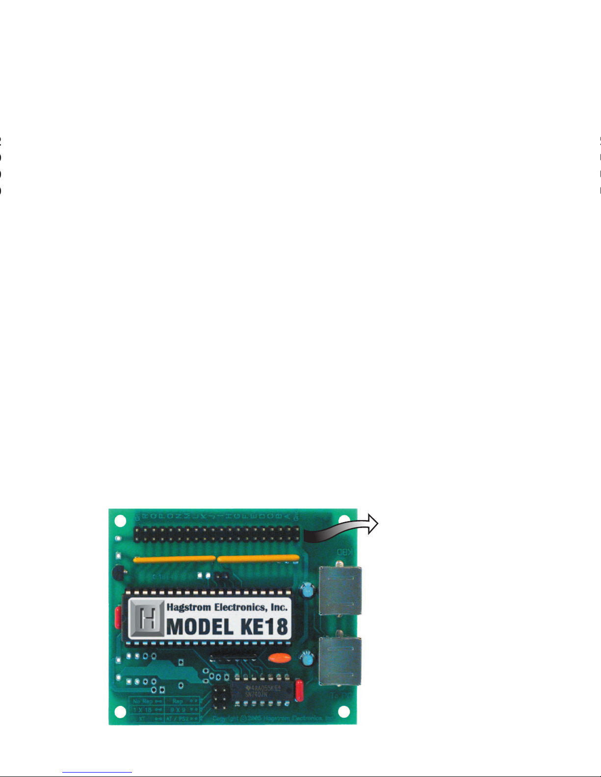
The 40 pin dual row header serves as the connection point to each of
the I/O pins on the KE18. This header accepts a variety of connectors,
including the plug on many off the shelf keypads. This header also
provides a convenient place for attachment of individual switches.
40 pin dual row
I/O Header
1
Page 4

Confi guring the KE18 Jumpers
The KE18 is designed to be easy to use. There are 3 jumpers located on
the board which allow for selection of various modes. These jumpers
must be set before using the product.
Jumper 1
This jumper selects the repeat function of the inputs on the KE18’s
I/O header.
With this jumper in place, inputs will send a single keystroke to the PC
when activated regardless of the length of time they are held on.
When this jumper is open, inputs on the KE18’s I/O header will repeat
their defi ned keystroke for the duration the input is held active or until
another input is activated.
Jumper 2
This jumper controls the scanning mode for the I/O header on the
KE18.
If this jumper is in place, the KE18 will scan the I/O header as 18
individual inputs (pins “A” through “R”). Keystrokes to the PC are
activated in the 18 input mode by making a connection between an
input pin and one of the logic ground pins (“Gnd”), provided at each
end of the I/O header.
With this jumper open, the KE18 scans the I/O header as a 9 Column
by 9 Row matrix. In this mode, keystrokes to the PC are generated by
connecting a switch such that one Row pin (“J” through “R”) and one
Column pin (“A” through “I”) are shorted together when the switch is
activated.
NOTE: See the Keycode Lookup Tables on page 6 for keystrokes
available in each of these modes.
2
KE-MM6
5 pin DIN Male/Male 6 foot cable. Connects
KE18 with 5 pin DIN connectors to computer.
KE-MM6-mini
6 pin miniDIN Male/Male 6 foot cable. Connects
KE18 with 6 pin miniDIN connectors to computer.
Page 5

Jumper 3
Use this jumper to select the type of PC with which the KE18 will be
used.
With this jumper removed (the most commonly used setting), the
KE18 operates in the PS/2 “AT” mode, compatible with Pentium and
X86 computers.
When this jumper is in place, the KE18 will operate as a PCXT type
keyboard. This mode allows for compatibility with early PCs and PCXT
based single board computers.
3
Jumper 1
Jumper 2
Jumper 3
NOTE: The jumpers
must be set before
power is applied.
Changing the jumper
settings with power on
will have no effect on
the options.
Page 6

Interfacing to the KE18 I/O Header
Interface of the KE18 to switches and keypads is accomplished by
connection to the 40 pin dual row I/O header. Each of the pins of the
header is connected in parallel with the adjacent pin. This provides 20
individual interface signals, with both the end pins being logic Ground.
The 18 connections are marked “A”-“R” are the KE18 inputs.
18 Input Mode
In the connection of a switch in
the 18 input mode, inputs are
activated by shorting them to
Ground (reference marked “Gnd”).
The example shows one side of
the switch is connected to input
pin “D” and the other is connected
to Ground (“Gnd”), producing the
keystroke “E” when activated (see
KE18 keycode lookup table on
page 6). There are 18 individual
inputs in this mode.
9x9 Matrix Mode
In the 9x9 matrix mode, inputs are
activated by shorting a Column
pin (“A” to “I”) to a Row pin (“J” to
“R”). The example shows input pin
“C” which is a Column, and input
pin “O” which is a Row, producing
the keystroke “X” when activated
(see KE18 keycode lookup table
on page 6). A total of 81 inputs
are available in this mode.
NOTE: KE18 inputs are for “Dry” contacts only! Never connect
any signal on the KE18 to an external voltage. TTL/CMOS levels
and analog switches are acceptable.
4
Connection to Computer and Keyboard
There are two miniDIN connectors on your KE18. Each of these
connectors has a different function.
The DIN connector which is marked “To PC” is for interface of the KE18
to the computer. Insert one end of a (male to male) shielded cable
into this port. The other end of the cable connects to the computer’s
keyboard input.
The DIN connector marked “KBD” is for using an external keyboard
with the KE18. Plug the keyboard into this port to use it in addition to
the KE18. Use of the keyboard is optional; a keyboard does not need
to be plugged into this port for the KE18 to operate.
NOTE: Always perform these connections with the computer’s
power off.
Page 7

Connection to Computer and Keyboard
There are two miniDIN connectors on your KE18. Each of these
connectors has a different function.
The DIN connector which is marked “To PC” is for interface of the KE18
to the computer. Insert one end of a (male to male) shielded cable
into this port. The other end of the cable connects to the computer’s
keyboard input.
The DIN connector marked “KBD” is for using an external keyboard
with the KE18. Plug the keyboard into this port to use it in addition to
the KE18. Use of the keyboard is optional; a keyboard does not need
to be plugged into this port for the KE18 to operate.
NOTE: Always perform these connections with the computer’s
power off.
5
KBD
TO PC
Page 8

Jumper 3
Use this jumper to select the type of PC with which the KE18 will be
used.
With this jumper removed (the most commonly used setting), the
KE18 operates in the PS/2 “AT” mode, compatible with Pentium and
X86 computers.
When this jumper is in place, the KE18 will operate as a PCXT type
keyboard. This mode allows for compatibility with early PCs and PCXT
based single board computers.
NOTE: The jumpers
must be set before
power is applied.
Changing the jumper
settings with power on
will have no effect on
the options.
KE18 Keycode Lookup Tables
The following tables list the keycodes that are sent to the computer by
the KE18 in response to activation of an input.
A B C D E F G H I J K L M N O P Q R
A C D E G I L O Q R S X
?/|
\
F1 Space Esc Enter
KE18 Keycode Lookup Table (18 Input Mode)
KE18 Header Input Pins
J K L M N O P Q R
A
A B C D E F G H I
B
J K L M N O P Q R
C
S T U V W X Y Z
Esc
D
:
;
“
‘
>
.
<
,
?
/
Space
Backspace
{
[
}
]
E
Ctrl Alt Shift Insert Delete Home End
Page UpPage
Down
F
/ * - + F1 F2 F3 F4 F5
G
8 9
Pg Up.Del
Enter F6 F7 F8 F9 F10
H
4
5
6 7
Home
_
-
|
\
Caps
Lock
Num
Lock
Print
Screen
I
0
Ins
1
End
2 3
Pg Dn+=
~
`
Tab Pause
Scroll
Lock
Header Row Pins
Header Column Pins
In this mode, keycodes to the computer are initiated by shorting
one input pin to the provided Ground connection. Example: Pin
“J” to Ground would produce an “R” on the computer.
Keycodes to the computer are initiated in this mode by shorting
one Row pin to one Column pin. Example: Row “J” to Column “C”
would produce an “S” on the computer.
KE18 Keycode Lookup Table (9x9 Matrix Mode)
6
*NOTE Please contact us for custom keycode information.
Page 9

Accessories
KE-MM6
5 pin DIN Male/Male 6 foot cable. Connects
KE18 with 5 pin DIN connectors to computer.
7
KE-MM6-mini
6 pin miniDIN Male/Male 6 foot cable. Connects
KE18 with 6 pin miniDIN connectors to computer.
Page 10

The KE18 PC Keyboard Encoder is a tool for interfacing switches
or keypads to your computer’s keyboard input. It provides all of the
necessary keyboard communication to your computer, and can
therefore take the place of the keyboard. The KE18 also features
a pass through port for the user’s PC keyboard, allowing both the
KE18 and the keyboard to be used together. This feature facilitates
development and testing of KE18 applications.
Power for the KE18 is obtained from the computer’s keyboard
connector. No external power supply is required.
The unit may be confi gured for use with compatible Pentium, PS/2,
X86, and PC XT computers.
The 18 pins labeled “A”-“R” on the I/O header provide a means for
converting switch closures to keystrokes sent directly to the computer.
These I/O pins are jumper confi gurable for operation as 18 individual
inputs, or as a 9x9 matrix. As a switch closure is detected, a code is
sent to your computer which corresponds to the input detected (see
keycode lookup tables on page 6).
The 40 pin dual row header serves as the connection point to each of
the I/O pins on the KE18. This header accepts a variety of connectors,
including the plug on many off the shelf keypads. This header also
provides a convenient place for attachment of individual switches.
Accessories
IOX36-KE18
Screw terminal block can be used to easily connect your device to the
KE18. 40 pin IDE ribbon cable included.
MTA100-10-12
MTA style connector, 10 individual wires, 12
inches long. Can be used to connect the I/O
header to your device. Sold as a set of two; 20
total wires. Custom lengths available (up to 10
feet); call for pricing.
MTA100-10-12
KE18 Header
8
Page 11

Warranty
HAGSTROM ELECTRONICS, INC. warrants this
product against defects in material or workmanship for a
period of ONE YEAR from the original purchase date. We will
repair or replace (at our option) the returned defective unit
at no charge during this warranty period.
No responsibility is assumed for any special, incidental,
or consequential damage resulting from the use of or
inability to use this product. In no case is HAGSTROM
ELECTRONICS, INC. to be liable for any amount which
exceeds the purchase price of the unit, regardless of the
claim.
No other warranty, written or verbal, is authorized. This
warranty is applicable only to units sold in the United States.
Units sold outside the United States are covered by a similar
warranty.
Depending on the state in which you live, you may have additional rights.
Great care has been taken during the assembly, testing, and burn-in
of your KE18 to ensure its performance. If you have any questions,
please send us an email or give us a call. Support is available Monday
through Friday, 8:00 am to 5:00 pm (EST).
customer service email: sales@hagstromelectronics.com
Call Toll Free 888-690-9080, or (540) 465-4677
NOTICE The KE18 product is designed to be used by technically
oriented computer users. When the KE18 is in use, your computer’s
signals and voltages are present on the unit. Prudent handling and
packaging is necessary to prevent damage to your computer.
Your keyboard encoder is designed for OEM use, and is not FCC part 15 approved. Because
the packaging and use of the product will directly affect the characteristics of the unit, it is the
responsibility of the purchaser to obtain fi nal approval of their application, if required.
PS/2, XT, and AT are Trademarks of International Business Machines.
Page 12

Toll Free 888-690-9080
Phone: (540) 465-4677 Fax: (540) 465-4678
Monday through Friday, 8:00 am to 5:00 pm (EST)
sales@hagstromelectronics.com
www.hagstromelectronics.com
1986 Junction Road, Strasburg, VA 22657
Copyright © 2017 HAGSTROM ELECTRONICS, INC.
V. 11.15
HAGSTROM
ELECTRONICS, INC.
 Loading...