

Page 1

Witty
Station de Charge
Elektrofahrzeug Ladestation
Charging station
Hager witty.eco & witty.premium
Notice d’installation /
Installationsanleitung /
Installation manual
Version 4.5.3
6LE003319D
1 / 36 30.01.2019
Page 2

Witty
Sommaire
1 Description générale des stations de charge ....................................................... 6
2 Ouverture de l’enveloppe extérieure.................................................................... 6
2.1 Composants électriques de la borne de charge ............................................ 7
3 Installation électrique ........................................................................................... 8
3.1 Protections .................................................................................................... 8
3.2 Qualité de la mise à la terre ........................................................................... 9
3.3 Bornes de raccordement ............................................................................... 9
3.4 Détection de contacts collés du contacteur ................................................... 9
4 Fixation et raccordement ................................................................................... 10
4.1 Schémas de perçage mural sans espace câblage arrière ........................... 10
4.2 Montage du support de fixation murale ....................................................... 11
4.3 Schémas d’installation au sol XEV418/19 + XEV420 .................................. 11
4.4 Alimentation électrique ................................................................................ 12
5 Paramétrage de la borne de recharge ............................................................... 13
5.1 Puissance de charge maximale ................................................................... 13
5.2 Charge immédiate ou différée ..................................................................... 13
5.3 Charge différée ............................................................................................ 14
5.4 Charge dynamique ...................................................................................... 15
6 Gestion du contrôle d’accès .............................................................................. 15
6.1 Accès contrôlé local ..................................................................................... 16
6.2 Accès contrôlé distant (uniquement XEV2xxC) ........................................... 17
7 Raccordement informatique .............................................................................. 17
8 Paramétrage du contrôleur ................................................................ ................ 19
8.1 Contrôle d’accès LOCAL ou DISTANT ........................................................ 19
8.2 Démarrage différé de charge par signal extérieur ....................................... 20
8.3 Effacement de charge lors d’un pic de consommation ................................ 22
8.4 Paramétrage de la communication bidirectionnelle ..................................... 24
Serveur distant vers Borne.................................................................... 24 8.4.1
Raccordement à une box internet ......................................................... 25 8.4.2
Raccordement à un modem GPRS avec IP fixe ................................... 27 8.4.3
Raccordement à un modem (ADSL ou GPRS) avec IP dynamique ...... 30 8.4.4
Borne vers serveur distant .................................................................... 31 8.4.5
9 Disfonctionnement ............................................................................................. 32
10 Maintenance électrique ................................................................................... 33
11 Données techniques ....................................................................................... 34
12 Comment éliminer ce produit .......................................................................... 34
2 / 36
Page 3

Witty
Inhalt
1 Allgemeine Beschreibung der Station.................................................................. 6
2 Entfernen der Gehäuseabdeckung ...................................................................... 6
2.1 Elektrische Komponenten der Station ........................................................... 7
3 Elektrische Installation ......................................................................................... 8
3.1 Absicherung .................................................................................................. 8
3.2 Qualität der Erdung ....................................................................................... 9
3.3 Anschlussklemmen ........................................................................................ 9
3.4 Erkennung verklebter Schützkontakte ........................................................... 9
4 Befestigung und Anschluss ............................................................................... 10
4.1 Bohrschema, Befestigung an einfache Wandhalterung ............................... 10
4.2 Montage einfache Wandhalterung ............................................................... 11
4.3 Schema zur Bodenmontage XEV418/19 + XEV420 .................................... 11
4.4 Elektrische Versorgung ............................................................................... 12
5 Konfiguration der Ladestation ............................................................................ 13
5.1 Maximaler Ladestrom .................................................................................. 13
5.2 Sofortladung oder zeitversetzte Ladung ...................................................... 13
5.3 Zeitversetzte Ladung ................................................................................... 14
5.4 Dynamische Ladung .................................................................................... 15
6 Einstellung der Nutzerauthentifizierung ............................................................. 15
6.1 Lokale Authentifizierung .............................................................................. 16
6.2 Online Nutzerauthentifizierung .................................................................... 17
7 Herstellen einer online Verbindung ................................................................... 17
8 Konfiguration des Ladecontrollers ..................................................................... 19
8.1 Nutzerauthentifizerung lokal oder online ..................................................... 19
8.2 Ladestart mittels externem Freischaltsignal ................................................ 20
8.3 Ladestopp zur Lastreduktion ....................................................................... 22
8.4 Konfiguration der bidirektionalen Kommunikation........................................ 24
8.4.1 Remote Serververbindung mit der Station ............................................ 24
8.4.2 Verbindung mit einem Router ............................................................... 25
8.4.3 Verbindung mit einem GPRS modem mit fester IP ............................... 27
8.4.4 Verbindung mit ADSL oder GPRS Modem mit dynamischer IP ............ 30
8.4.5 Remote Verbindung zum Server ........................................................... 31
9 Fehlfunktion ....................................................................................................... 32
10 Elektrische Wartung ........................................................................................ 33
11 Technische Daten ........................................................................................... 34
12 Korrekte Entsorgung dieses Produkts ............................................................ 34
3 / 36
Page 4

Witty
Contents
1 General description of charging station ............................................................... 6
2 Removing the enclosure cover ............................................................................ 6
2.1 Electrical components of charging station ..................................................... 7
3 Electrical installation ............................................................................................ 8
3.1 Protection ...................................................................................................... 8
3.2 Quality of earthing ......................................................................................... 9
3.3 Connection terminals ..................................................................................... 9
3.4 Detection of welded contactor contacts ......................................................... 9
4 Fixation and connection ..................................................................................... 10
4.1 Drilling scheme, mounting basic wall fixation .............................................. 10
4.2 Mounting basic wall fixation ......................................................................... 11
4.3 Scheme for ground mounting XEV418/19 + XEV420* ................................. 11
4.4 Electrical supply........................................................................................... 12
5 Configuration of charging station ....................................................................... 13
5.1 Maximum charge current ............................................................................. 13
5.2 Immediate or postponed charging .............................................................. 13
5.3 Postponed charging ..................................................................................... 14
5.4 Dynamic charging ........................................................................................ 15
6 Managing user authentications .......................................................................... 15
6.1 Local authentication ..................................................................................... 16
6.2 Online user authentication ........................................................................... 17
7 Establish online connection ............................................................................... 17
8 Configuration of charge controller ..................................................................... 19
8.1 User authentication local or online ............................................................... 19
8.2 Initiating start of charge by external signal .................................................. 20
8.3 Demand reduction by stop of charge ........................................................... 22
8.4 Configuration of bidirectional communication .............................................. 24
8.4.1 Remote connection to charging station ................................................. 24
8.4.2 Connection to a router .......................................................................... 25
8.4.3 Connection to a GPRS modem with fixed IP......................................... 27
8.4.4 Connection to an ADSL or GPRS modem with dynamic IP .................. 30
8.4.5 Remote connection to server ................................................................ 31
9 Malfunction ........................................................................................................ 32
10 Electrical Maintenance .................................................................................... 33
11 Technical characteristics................................................................................. 34
12 Correct Disposal of this product ...................................................................... 34
4 / 36
Page 5
Witty
Précautions initiales
Erste Vorsichtsmaßnahmen
Initial precautions
5 / 36
Page 6

Witty
français
deutsch
english
1
Prise Mode 3 Type 2S
(verrouillable)
Ladesteckdose Mode 3,
(verriegelbar)
Socket Mode 3 with interlock
2
Prise Mode 2
(Prise domestique - option)
Ladesteckdose Mode 2
(Schuko - option)
Standard socket
(option)
3
Rangement fiche
Steckerlager
Plug Storage
4
Lecteur Carte RFID
(option)
RFID Kartenleser
(option)
RFID card reader
(option)
5
Bouton poussoir
(Marche forcée en cas de
départ de charge différé)
Taster
(Sofort-start wenn
Zeitversetzte Ladung)
Push Button
(Immediate charging in case
of Postponed charging)
6
Bandeau lumineux
LED Anzeige
LED display
1 2 3 4 5 6 5 6 3 1 2
1 Description générale des stations de charge
1 Allgemeine Beschreibung der Station
1 General description of charging station
2 Ouverture de l’enveloppe extérieure
2 Entfernen der Gehäuseabdeckung
2 Removing the enclosure cover
L’ouverture de l’enveloppe extérieure se fait par l’intermédiaire de vis /
Zum Entfernen der Gehäuseabdeckung werden Schrauben gelöst /
The enclosure cover can be removed by releasing screws
6 / 36
Page 7

Witty
3 1 4 7 8
2
6
5
8
9
2.1 Composants électriques de la borne de charge
2.1 Elektrische Komponenten der Station
2.1 Electrical components of charging station
Le coffret intérieur est composé des éléments suivants /
Der innere Verteiler setzt sich aus folgenden Komponenten zusammen /
The inner enclosure is composed of following components
7 / 36
Page 8

Witty
français
deutsch
english
1
Détection Contact collé
Contacteur selon le modèle
Erkennung verklebter
Schützkontakte, je nach
Ausführung
Detection of welded
contactor contacts,
depending on the model
2
Prise M3T2S (verrouillable)
M3T2S Ladesteckdose
(veriegelbar)
M3T2S socket with
interlock
3
Prise M2TE
M2TE Ladesteckdose
M2TE socket
4
Plaque Passe Câbles
Kabelführung
Cable management
5
Controleur
Ladecontroller
charge controller board
6
Carte TCP/IP
TCP/IP Karte
TCP/IP card
7
Alimentation électronique
Elektronikstromversorgung
Electronic power supply
8
Contacteurs + Disjoncteurs
Schütz + Leistungsschalter
Contactors + breakers
9
Borniers de raccordement
Reihenklemmen
Terminals
3 Installation électrique
3 Elektrische Installation
3 Electrical installation
3.1 Protections
3.1 Absicherung
3.1 Protection
8 / 36
Page 9

Witty
français
deutsch
english
1
100 maxi pour les 10
bornes
Max. 100 für 10 Stationen
Max. 100 for 10 stations
2
10 bornes max sur 1 terre
Max. 10 Stationen auf 1
Erdung
Max. 10 stations on 1
earthing
3
Interconnexion
Zusammenschaltung
Interconnection
OK
NOK
REGIME DE
NEUTRE /
NETZFORM /
EARTHING
SYSTEM
IT
1 System
REGIME DE NEUTRE / NETZFORM /
EARTHING SYSTEM
TN / TT
2
max.
100
3
1
3.2 Qualité de la mise à la terre
3.2 Qualität der Erdung
3.3 Quality of earthing
3.3 Bornes de raccordement
3.4 Anschlussklemmen
3.2 Connection terminals
Les bornes de raccordement au réseau sont prévues pour des câbles de diamètre
flexible 10mm2 (16 mm2) /
Die Netzanschlussklemmen sind für flexibel10mm2 (starr 16 mm2) ausgelegt /
The connection terminals are suitable for flexible 10mm2 (rigid 16 mm2)
3.4 Détection de contacts collés du contacteur
Erkennung verklebter Schützkontakte
3.3 Detection of welded contactor
Toutes les bornes witty ayant une puissance de charge nominale supérieure à 3,6kW
sont pourvues d’un dispositif de détection de contact collé du contacteur /
Die Ladestationen größer 3,6kW Ladeleistung überwachen die korrekte Funktion der
Leistungsschütze /
Charging stations with charge powers greater than 3,6kW are monitoring the correct
operation of the internal power contactors
9 / 36
Page 10

Witty
français
deutsch
english
1
2
Bobine À Emission MZ203
Arbeitsstromauslöser MZ203
Shunt trip MZ203
3
Déconnexion Réseau Si
Contacteur collé
Trennung vom Netz, falls der
Schütz verklebt
Disconnection from grid if
contactor welded
4
Puissance > 4kVA
uniquement
Nur Leistung > 4kVA
Power > 4kVA only
5
Protection intégrée
Dans la carte électronique
Integrierter Schutz
in der Platine
Integrated protection
in the board
error
detected
Constant
red warning
light
3s
Disconnection
From grid
Fehler
erkannt
Konstant rote
Warnleuchte
3s
Trennung
vom Netz
Défaut
détecté
Information
Voyant
Rouge Fixe
3s
Déconnexion
Réseau
4 Fixation et raccordement
4 Befestigung und Anschluss
4 Fixation and connection
4.1 Schémas de perçage mural sans espace câblage arrière
4.1 Bohrschema, Befestigung an einfache Wandhalterung
4.1 Drilling scheme, mounting basic wall fixation
10 / 36
Page 11

Witty
4.2 Montage du support de fixation murale
4.2 Montage einfache Wandhalterung
4.2 Mounting basic wall fixation
4.3 Schémas d’installation au sol XEV418/19 + XEV420
4.3 Schema zur Bodenmontage XEV418/19 + XEV420
4.3 Scheme for ground mounting XEV418/19 + XEV420*
11 / 36
Page 12

Witty
français
deutsch
english
1
Zone de Fixation Borne
Befestigungsbereich des
Systems
System attachement zone
2
Fondation C20/25, X0
Profondeur 80cm
Fundament C20/25, X0
Tiefe 80cm
Foundation C20/25, X0
Depth 80cm
3
Couche de Propreté 5cm,
C8/10
Unterlagerschicht 5cm,
C8/10
Subbase 5cm, C8/10
français
Deutsch
english
1
Borniers Puissance 10mm2
maxi - rigide 16mm2
Leistungsklemmen max.
10mm2 - massiv 16mm2
Power terminals max. 10mm
2
- massiv 16mm2
4.4 Alimentation électrique
4.4 Elektrische Versorgung
4.4 Electrical supply
12 / 36
Page 13

Witty
2
6
4
1
3
5
5 Paramétrage de la borne de recharge
5 Konfiguration der Ladestation
5 Configuration of charging station
5.1 Puissance de charge maximale
5.1 Maximaler Ladestrom
5.1 Maximum charge current
5.2 Charge immédiate ou différée
5.2 Sofortladung oder zeitversetzte Ladung
5.2 Immediate or postponed charging
13 / 36
Page 14

Witty
français
deutsch
english
1
Charge immédiate
Sofortladung
Immediate charging
2
Autorisation immédiate
Sofortige Autorisierung
Immediate authorization
3
Charge différée
Zeitversetze Ladung
Postponed charging
4
Signal Tarif de Nuit
du comteur
Nachtstromsignal
vom Zähler
Night tariff signal
from main meter
5
Autorisation conditionnée
Bedingte Freischaltung
durch ext. Signal
Conditional authorization
6
Charge VE
Laden des EV
Charging EV
français
deutsch
english
1
Contrôleur /
Steuereinheit /
Controller
Armoire électrique /
Schaltschrank / switch
cabinet
System
Câble / Kabel / Cable 2x1,5 mm
2
Borne /
Klemmen /
Terminals
50 & 51 bei XEV2XX
60 & 61 bei XEV1XX
Borne / 230V AC Signal/
Terminals C1 & C2
Borne
éteinte
Controleur
50&51 / 60&61
Compteur
C1 & C2
System
ausgeschaltet
Steuereinheit
50&51 / 60&61
Zähler
C1 & C2
System
off
Controller
50&51 / 60&61
Main meter
C1 & C2
1
5.3 Charge différée
5.3 Zeitversetzte Ladung
5.3 Postponed charging
Compteur avec Entrée Jour/Nuit + Borne en mode NUIT /
Zähler mit Nachtstromsignal + Ladestation im zeitversetzten Lademodus /
Main metering with night tariff signal + charging station in postponed charging mode
14 / 36
Page 15

Witty
français
deutsch
english
1
Borne
éteinte
Controleur
53&54 / 63&64
Compteur
I1 & I2
System
ausgeschaltet
Steuereinheit
53&54 / 63&64
Zähler
I1 & I2
System
off
Controller
53&54 / 63&64
Main meter
I1 & I2
Borne /
Klemmen /
Terminals
53 & 54 bei XEV2XX
63 & 64 bei XEV1XX
5.4 Charge dynamique
5.4 Dynamische Ladung
5.4 Dynamic charging
Compteur avec Protocol TIC
Zähler mit TIC signal
Main metering with TIC signal
6 Gestion du contrôle d’accès
6 Einstellung der Nutzerauthentifizierung
6 Managing user authentications
15 / 36
Page 16

Witty
français
deutsch
english
1
Clé USB
(livrée uniquement avec XEV2xx)
USB-Stick
(nur mit XEV2xx geliefert)
USB stick
(only delivered with XEV2xx)
2
Transférer via clé USB
Übertragung
mit dem USB-Stick
Transfer via USB stick
3
Technologies :
Mifare 1k ou 4k
Mifare Ultralight NTAG203
Technologien:
Mifare 1k oder 4k
Mifare Ultralight NTAG203
Technologies :
Mifare 1k or 4k
Mifare Ultralight NTAG203
1 2 3
4
5
6
6.1 Accès contrôlé local
6.1 Lokale Authentifizierung
6.1 Local authentication
+ Paramétrage du contrôleur (voir chapitre concerné) /
+ Konfiguration des Ladecontrollers (siehe entsprechendes Kapitel) /
+ Configuration of charge controller (see concerned chapter)
16 / 36
Page 17

Witty
français
deutsch
english
1
Numéro d’ordre à définir
Reihenfolge der Nummern
festlegen
Set order of numbers
2
Numéro de la Carte RFID en
Hexadécimal
RFID-Kartennummer in
Hexadezimal
RFID card number in
hexadecimal
3
Durée maxi de la session de
charge (si vierge = infini)
Maximale Dauer eines
Ladevorgangs (falls leer =
unbegrenzt)
Maximum duration of
charging session (if blank =
unlimited)
4
Déclaration des utilisateurs
pouvant démarrer et stopper
LEUR session de charge
Deklaration der Nutzer, die
nur IHREN Ladevorgang
starten und stoppen können
Declaration of users that can
start and stop only THEIR
charging session
5
Déclaration des superutilisateurs pouvant stopper
TOUTES les sessions de
charge en cours
(permanent, surveillant)
Deklaration der Super-User,
die JEDEN Ladevorgang
stoppen können
Declaration of super users
that can stop ANY charging
session
(permanent, supervisor)
6
À droite du signe # = zone de
commentaire et d’explication
Rechts eines # =
Kommentare und
Erklärungen
To the right of a # =
comments and explanations
6.2 Accès contrôlé distant (uniquement XEV2xxC)
6.2 Online Nutzerauthentifizierung
6.2 Online user authentication
+ Paramétrage du contrôleur (voir chapitre concerné) /
+ Konfiguration des Ladecontrollers (siehe entsprechendes Kapitel) /
+ configuration of charge controller (see concerned chapter)
7 Raccordement informatique
7 Herstellen einer online Verbindung
7 Establish online connection
17 / 36
Page 18

Witty
français
deutsch
english
1
Communication
Bidirectionelle:
Ouverture port nécessaire
Routage Adresse IP à définir
Bidirektionale
Kommunikation:
Portöffung notwendig
Routing-IP-Adresse festlegen
Bidirectional communication:
Port opening necessary
Set Routing IP address
18 / 36
Page 19

Witty
français
deutsch
english
1
Clé USB
(livrée uniquement avec XEV2xx)
USB-Stick
(nur mit XEV2xx geliefert)
USB stick
(only delivered with XEV2xx)
2
Transférer via clé USB
Übertragung
mit dem USB-Stick
Transfer via USB stick
3
Accés controlé LOCAL
Nutzerauthentifizierung
LOKAL
User authentification LOCAL
4
Accés controlé DISTANT
Nutzerauthentifizierung
ONLINE
User authentification
ONLINE
8 Paramétrage du contrôleur
8 Konfiguration des Ladecontrollers
8 Configuration of charge controller
8.1 Contrôle d’accès LOCAL ou DISTANT
8.1 Nutzerauthentifizerung lokal oder online
8.1 User authentication local or online
19 / 36
Page 20

Witty
français
deutsch
english
0
sans contrôle, home version
Ohne Nutzerauthentifizierung
Free of charge
1
Contrôle d’accès LOCAL
Nutzerauthentifizierung
LOKAL
User authentification LOCAL
2
Contrôle d’accès DISTANT
Nutzerauthentifizierung
ONLINE
User authentification
ONLINE
3
À droite du signe # = zone de
commentaire et d’explication
Rechts eines # =
Kommentare und
Erklärungen
To the right of a # =
comments and explanations
français
deutsch
english
1
Clé USB
(livrée uniquement avec XEV2xx)
USB-Stick
(nur mit XEV2xx geliefert)
USB stick
(only delivered with XEV2xx)
2
Transférer via clé USB
Übertragung
mit dem USB-Stick
Transfer via USB stick
1 2 3
PIN65 (XEV2…)
PIN42 (XEV1…)
Fichier/Datei/file << bxxxx config.cfg >> ou/oder/or << bxxxx global.cfg >>
8.2 Démarrage différé de charge par signal extérieur
8.2 Ladestart mittels externem Freischaltsignal
8.2 Initiating start of charge by external signal
20 / 36
Page 21

Witty
3
Prise en compte
Signal extérieur de
démarrage
Berücksichtigung eines
Externen Startsignals
Consideration of
External starting signal
4
Signal extérieur
Co-Génération Horloge
24VDC
Externes Signal vom
Blockheizkraftwerk
24VDC
External signal from
Cogeneration unit
24VDC
5
Glissière
Schiebeschalter
Slide switch
6
Bornier Entrées
Klemmeneingänge
Terminal board inputs
français
deutsch
english
1
0 = Signal extérieur de
Démarrage de charge
0 = Externes Signal zum
Starten des Ladevorgangs
0 = External signal to
Start the charging session
2
À droite du signe # = zone de
commentaire et d’explication
Rechts eines # =
Kommentare und
Erklärungen
To the right of a # =
comments and explanations
1
2
Fichier/Datei/file << bxxxx config.cfg >> ou/oder/or << bxxxx global.cfg >>
Dans ce cas, toute charge commencée suite à l’apparition du signal 24V sera
terminée, même si le 24V signal extérieur n’est plus activé /
Ladung startet bei aktivem externen 24V Signal /
Charging will start with an active external 24V signal
21 / 36
Page 22

Witty
français
deutsch
english
1
Clé USB
(livrée uniquement avec XEV2xx)
USB-Stick
(nur mit XEV2xx geliefert)
USB stick
(only delivered with XEV2xx)
2
Transférer via clé USB
Übertragung
mit dem USB-Stick
Transfer via USB stick
3
Prise en compte
Signal extérieur
d’effacement
Berücksichtigung eines
Externen Stoppsignals
Consideration of
External stopping signal
4
Signal extérieur
Co-Génération Horloge
24VDC
Externes Signal vom
Messsensor
24VDC
External signal from
Measuring sensor
24VDC
5
Glissière
Schiebeschalter
Slide switch
6
Bornier Entrées
Klemmeneingänge
Terminal board inputs
PIN65 (XEV2…)
PIN42 (XEV1…)
or
8.3 Effacement de charge lors d’un pic de consommation
8.3 Ladestopp zur Lastreduktion
8.3 Demand reduction by stop of charge
22 / 36
Page 23

Witty
français
deutsch
english
1
1 = Signal extérieur
D’effacement de charge
1 = Externes Signal zum
Ladesstopp
1 = External signal fpr
Load shedding
2
0 = Effacement partiel
1 = Effacement Total
0 = partielle Ladereduktion
1 = totaler Ladestopp
0 = partial load readuction
1 = total erasure
3
À droite du signe # = zone de
commentaire et d’explication
Rechts eines # =
Kommentare und
Erklärungen
To the right of a # =
comments and explanations
1
2
3
Fichier/Datei/file << bxxxx config.cfg >> ou/oder/or << bxxxx global.cfg >>
Dans ce cas, toute charge commencée s’arrêtera dès que le signal extérieur 24Vdc
apparait et reprendra s’il disparait (attention : 3 effacements successifs maximum par
session de charge sont autorisés). /
Ladung wird bei aktivem externen 24V Signal gestoppt, und startet sobald Signal
nicht mehr anliegt /
Charge will stop while 24V signal is active and restart when signal is not present any
more
23 / 36
Page 24
Witty
français
Deutsch
english
1
ADSL – FAI IP fixe
(standard ou paramétré)
ADSL – FAI feste IP
(Standard oder eingestellt)
ADSL – FAI fixed IP
(Standard or set)
2
GPRS – SIM publique –
FAI IP fixe
GPRS – öffentliche SIM –
FAI feste IP
GPRS – public SIM –
FAI fixed IP
3
1. ADSL – FAI
IP dynamique
1. ADSL – FAI
dynamische IP
1. ADSL – FAI dynamic IP
2. GPRS – SIM publique –
FAI IP dynamique
2. GPRS – öffentliche SIM –
FAI dynamische IP
2. GPRS – public SIM –
FAI dynamic IP
5
Permettre une
communication descendante
du serveur distant VERS la
borne
Erlauben Sie DownlinkKommunikation vom
Remote-Server ZUR Station
Allow downlink
communication from the
remote server TO the station
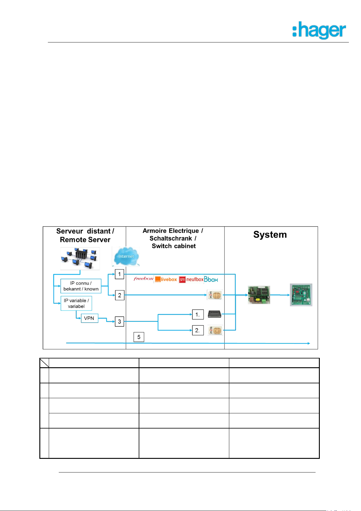
8.4 Paramétrage de la communication bidirectionnelle
8.4 Konfiguration der bidirektionalen Kommunikation
8.4 Configuration of bidirectional communication
Serveur distant vers Borne 8.4.1
8.4.1 Remote Serververbindung mit der Station
8.4.1 Remote connection to charging station
Afin de communiquer avec la borne, il est indispensable de pouvoir connaitre à tout
instant l’adresse IP du point d’accès internet de la borne ainsi que le routage interne
pour trouver la borne /
Bevor mit der Station kommuniziert werden kann muss die IP Adresse der Station
dem verbundenen Server bekannt sein /
The IP address of the charging station has to be known by the connected server all
times
Suivant les projets, une des configurations suivantes sera à privilégier /
Konfigurationsmöglichkeiten nachfolgend /
Configuration possibilities in the following
24 / 36
Page 25

Witty
français
Deutsch
english
1
ADSL – FAI IP fixe
(standard ou paramétré)
ADSL – FAI feste IP
(Standard oder eingestellt)
ADSL – FAI fixed IP
(Standard or set)
1.1
Règle de routage à définir
(NAT)
Routing Einstellungen
festlegen (NAT)
Set routing settings (NAT)
1.2
Figer Adresse IP
et Sous-Réseau
Feste IP-Adresse
und Subnetzwerk
Fixed IP address
and Subnetwork
5
Permettre une
communication descendante
du serveur distant VERS la
borne
Erlauben Sie DownlinkKommunikation vom
Remote-Server ZUR Station
Allow downlink
communication from the
remote server TO the station
Raccordement à une box internet 8.4.2
8.4.2 Verbindung mit einem Router
8.4.2 Connection to a router
1.1 FR : Paramétrage de la box (Exemple d’une freebox révolution)
1) Interface administrateur : http://mafreebox.freebox.fr/ + mot de passe
2) menu « Réseau local »
3) onglet « Redirection de port ». (règle de NAT, serveur virtuel NAT ou serveur
LAN pour d’autres box)
4) Définition du port externe =80 pour la box
5) Protocole TCP
6) Adresse IP = adresse locale de la borne = 192.168.120.120 par exemple
7) Port interne = port de la borne = 8080
25 / 36
Page 26

Witty
français
Deutsch
english
1
Règle d’attribution IP
IP FIXE
DHCP = 0
IP-Zuordnungsregel
FESTE IP
DHCP = 0
IP assingnment rule
FIXED IP
DHCP = 0
2
IP local fixe de la borne
192.168.120.120
+ sous masque
255.255.255.0
Feste lokale IP der Station
192.168.120.120
+ Subnetzmaske
255.255.255.0
Fixed local IP of Station
192.168.120.120
+ subnetmask
255.255.255.0
3
Adresse du serveur distant
+ login/password
Remote-Serveradresse
+ login/password
Remote server address
+ login/password
3 2 1
1.2 Paramétrage de la borne /
Konfiguration der Station /
Configuration of station
26 / 36
Page 27

Witty
français
Deutsch
english
2
GPRS – SIM publique –
FAI IP fixe
GPRS – öffentliche SIM –
FAI feste IP
GPRS – public SIM –
FAI fixed IP
2.1
Carte SIM M2M
IP publique & fixe
M2M SIM-Karte
Öffentliche & feste IP
M2M SIM card
Public & fixed IP
2.2
Règle de routage à définir
(APN & NAT)
Routing Einstellungen
festlegen (APN & NAT)
Set routing settings
(APN & NAT)
2.3
Figer Adresse IP
et Sous-Réseau
Feste IP-Adresse
und Subnetzwerk
Fixed IP address
and Subnetwork
5
Permettre une
communication descendante
du serveur distant VERS la
borne
Erlauben Sie DownlinkKommunikation vom
Remote-Server ZUR Station
Allow downlink
communication from the
remote server TO the station
Raccordement à un modem GPRS avec IP fixe 8.4.3
8.4.3 Verbindung mit einem GPRS modem mit fester IP
8.4.3 Connection to a GPRS modem with fixed IP
2.1 Acheter une carte SIM M2M /
Kauf einer M2M SIM Karte /
Buy M2M sim card
Spécificités / Spezifikation / Specification:
IP Publique / öffentlich / public
IP Fixe ou statique / fest oder statisch / fixed or static
Connaitre l’APN / Kenntnis des APNs / know APN name (Access Point
Name ou Nom du Point d’Accès)
27 / 36
Page 28

Witty
2.2 Paramétrage du modem /
Konfiguration /
Configuration modem
(Exemple LS300 de sierra)
Règle de routage de l’extérieur vers la borne /
Anbindung nach extern herstellen /
Setup external connectivity
1) Interface administrateur/ webbasierte Konfiguration/ webbased config :
http://192.168.13.31:9191
2) Login = user + mot de passe = 12345
3) Onglet/Reiter/slider « Security ». (règle de NAT, serveur virtuel NAT ou
serveur LAN pour d’autres modem)
4) Activer Port Forwarding = Enable
5) Public Start Port = 80
6) Public End Port = 0 (ou 80 suivant les modems)
7) Protocole TCP
8) Host IP = adresse locale de la borne = 192.168.120.120 par exemple
9) Port interne = port de la borne = 8080
10) Valider par Apply
28 / 36
Page 29

Witty
français
Deutsch
english
1
Règle d’attribution IP
IP FIXE
DHCP = 0
IP-Zuordnungsregel
FESTE IP
DHCP = 0
IP assingnment rule
FIXED IP
DHCP = 0
2
IP local fixe de la borne
192.168.120.120
+ sous masque
255.255.255.0
Feste lokale IP der Station
192.168.120.120
+ Subnetzmaske
255.255.255.0
Fixed local IP of Station
192.168.120.120
+ subnetmask
255.255.255.0
3
Adresse du serveur distant
+ login/password
Remote-Serveradresse
+ login/password
Remote server address
+ login/password
1 2 3
Paramétrer le Point d’accès au Réseau Internet du Modem /
Netzeinstellungen vornehmen /
Prepare mobile provider configuration
1) Onglet / Reiter / slider « WAN/Cellular »
2) Paragraphe Network Credentials GSM
3) APN Type = User Entry (c’est vous qui définissez le le nom de l’APN)
4) User Entered APN = Nom du Point d’accès APN de votre carte SIM
5) SIM PIN = option si votre carte SIM possède un code PIN
6) Valider par / Bestätigen / confirm : Apply
7) Reboot du modem
2.3 Paramétrage de la borne /
Online Konfiguration der Station /
Online setup of charging station
29 / 36
Page 30

Witty
français
Deutsch
english
3
1. ADSL – FAI
IP dynamique
1. ADSL – FAI
dynamische IP
1. ADSL – FAI dynamic IP
2. GPRS – SIM publique –
FAI IP dynamique
2. GPRS – öffentliche SIM –
FAI dynamische IP
2. GPRS – public SIM –
FAI dynamic IP
3.1
Activier un tunnel VPN
(compatible avec le
matériel retenu (modem))
Aktiviere VPN Tunnel
(kompatibel mit Hardware
(Modem))
Activate VPN tunnel
(compatible with hardware
(modem))
3.2
Définir tunnel VPN,
Point d’accès APN
et serveur DHCP
VPN-Tunnel,
APN Zugangspunkt
und DHCP-Server festlegen
Set VPN tunnel,
APN access point
and DHCP server
3.3
Activer le DHCP
DHCP aktivieren
Activate DHCP
5
Permettre une
communication descendante
du serveur distant VERS la
borne
Erlauben Sie DownlinkKommunikation vom
Remote-Server ZUR Station
Allow downlink
communication from the
remote server TO the station
Raccordement à un modem (ADSL ou GPRS) avec IP dynamique 8.4.4
8.4.4 Verbindung mit ADSL oder GPRS Modem mit dynamischer IP
8.4.4 Connection to an ADSL or GPRS modem with dynamic IP
Ce type d’installation est à définir et coordonner avec le responsable informatique
du client /
Diese Installationsart ist mit dem IT Verantwortlichen des Kunden abzustimmen /
This installation has to be prepared in accordance with the IT responsible person
of the customer
30 / 36
Page 31

Witty
français
Deutsch
english
4
1. Box / Modem filaire
1. Kabelmodem
1. Wired modem
2. Modem GPRS
2. GPRS-Modem
2. GPRS modem
4.1
Déclarer l’adresse MAC de
la borne au niveau du
serveur
Deklarieren Sie die MACAdresse der Station auf dem
Server
Declare the MAC address of
station at the server
4.2
Déclarer l’adresse du
serveur
Deklarieren Sie die
Server-Adresse
Declare the server address
5
Permettre une
communication montante de
la borne VERS le serveur
distant
Erlauben Sie UplinkKommunikation von der
Station ZUM Remote-Server
Allow uplink communication
from the station TO the
remote server
français
Deutsch
english
1
Adresse du serveur distant
+ login/password
Remote-Serveradresse
+ login/password
Remote server address
+ login/password
1
Borne vers serveur distant 8.4.5
8.4.5 Remote Verbindung zum Server
8.4.5 Remote connection to server
31 / 36
Page 32

Witty
Nombre
d’impulsions /
Anzahl der
Blinkimpulse /
LED pulse
pattern
Type de défaut /
Fehlerart /
type of malfunction
Cause /
Fehlerursache /
Origin of malfunction
1
Défaut câble de charge /
Defekt Ladeleitung /
Defect charging cable
Câble défectueux ou non supporté
(13A) /
Leitung defekt oder nicht unterstützte
Belastbarkeit (13A) /
Cable defect or not supported current
(13A)
2
Communication défectueuse /
Kommunikation gestört /
Disturbed communication
Câble défectueux - court-circuit au
niveau communication /
Kommunikationsleitung defekt,
Kurzschluss /
Communication wiring malfunction.
Short circuit
3
Véhicule électrique surchargé /
Leistungsüberschreitung /
Overload
Le VE ne respecte pas la limitation de
puissance imposée par la borne /
Elektrofahrzeug überschreitet den
maximal zulässigen Ladestrom /
Electric vehicle exceeds the power
limitation of station
4
Ventilation nécessaire /
Ventilation wird benötigt /
Ventilation required
Le véhicule nécessite une ventilation
supplémentaire (la charge est
bloquée) /
Fahrzeug fordert zusätzliche
Ventilation an, die Ladung wird
blockiert /
Vehicle requires additional ventilation,
charge is blocked
System
Voyant
Rouge clignotant /
Rotes Blinksignal /
Red flashing signal
9 Disfonctionnement
9 Fehlfunktion
9 Malfunction
32 / 36
Page 33

Witty
5
Défaut dans la gestion de la
charge /
Fehler beim Lastmanagement /
Error during loadmanagement
Le délestage de la charge est trop
fréquent (4x) et l’alimentation
électrique de la maison n’est pas
suffisante /
Das Fahrzeug wurde aufgrund von
Lastmanagement 4x abgeschaltet, die
Leistung ist nicht ausreichend /
Vehicle charge has been interrupted 4
times due to insufficient power offer
6
Communication défectueuse /
Kommunikation gestört /
Disturbed communication
Câble défectueux - problème au
niveau diode /
Kommunikationsleitung defekt,
Diodenfehler /
Communication wiring malfunction.
Diode failure
10 Maintenance électrique
10 Elektrische Wartung
10 Electrical Maintenance
Comme tout produit de l’installation électrique fixe, la qualité des serrages aux
différents points de connexion de l’installation qui doivent être en phase avec les
couples suivants.
Vor Inbetriebnahme sind die Drehmomente der Klemmstellen entsprechend der
Vorgaben zu überprüfen.
Before powering the charging station, please ensure that the torques for all the
screws are in line with the following drawing.
33 / 36
Page 34

Witty
Température /
Temperatur /
Temperature
-25°C à + 40°C
Humidité / Luftfeuchtigkeit / Humidity
5% à 95%
Coefficient de protection /
Schutzart / protection degree
IP 54 – IK 10
Tension /
Versorgungsspannung /
Supply voltage
230V / 400V (3-phase Version)
+/- 10%
Frequence / Frequenz / frequency
50 Hz +/- 1%
Puissance de charge maximum /
Maximale Ladeleistung /
Maximum charging power
32A - 7kW (1-phase Version)
32A - 22kW (3-phase Version)
Classe de protection électrique /
Schutzklasse /
Protection class
Classe 1 /
Klasse 1 /
Class 1
11 Données techniques
11 Technische Daten
11 Technical characteristics
Environnement de la station de charge /
Umgebungsbedingungen /
Environmental conditions
Caractéristiques électriques / Elektrische Daten / electrical specifications
12 Comment éliminer ce produit
12 Korrekte Entsorgung dieses Produkts
12 Correct Disposal of this product
34 / 36
Page 35

Witty
(déchets d’équipements électriques et électroniques).
(Applicable dans les pays de l’Union Européenne et aux autres pays
européens disposant de systèmes de collecte sélective).
Ce symbole sur le produit ou sa documentation indique qu’il ne doit pas être éliminé
en fin de vie avec les autres déchets ménagers. L’élimination incontrôlée des
déchets pouvant porter préjudice à l’environnement ou à la santé humaine, veuillez
le séparer des autres types de déchets et le recycler de façon responsable. Vous
favoriserez ainsi la réutilisation durable des ressources matérielles.
Les particuliers sont invités à contacter le distributeur leur ayant vendu le produit ou
à se renseigner auprès de leur mairie pour savoir où et comment ils peuvent se
débarrasser de ce produit afin qu’il soit recyclé en respectant l’environnement.
Les entreprises sont invitées à contacter leurs fournisseurs et à consulter les
conditions de leur contrat de vente. Ce produit ne doit pas être éliminé avec les
autres déchets commerciaux.
(Anzuwenden in den Ländern der Europäischen Union und anderen europäischen
Ländern mit einem separaten Sammelsystem).
Die Kennzeichnung auf dem Produkt bzw. auf der dazugehörigen Dokumentation
gibt an, dass es nach seiner Lebensdauer nicht zusammen mit dem normalen
Hausmüll entsorgt werden darf. Entsorgen Sie dieses Gerät bitte getrennt von
anderen Abfällen, um der Umwelt bzw. der menschlichen Gesundheit nicht durch
unkontrollierte Müllbeseitigung zu schaden. Recyceln Sie das Gerät, um die
nachhaltige Wiederverwertung von stofflichen Ressourcen zu fördern.
Private Nutzer sollten den Händler, bei dem das Produkt gekaut wurde, oder die
zuständigen Behörden kontaktieren, um in Erfahrung zu bringen, wie sie das Gerät
auf umweltfreundliche Weise recyceln können. Gewerbliche Nutzer sollten sich an
ihren Lieferanten wenden und die Bedingungen des Verkaufsvertrags konsultieren.
Dieses Produkt darf nicht mit anderem Gewerbemüll entsorgt werden.
(Waste Electrical & Electronic Equipment). z
(Applicable in the European Union and other European countries with
separate collection systems).
This marking shown on the product or its literature indicates that it should
not be disposed with other household waste at the end of its working life. To
prevent possible harm to the environment or human health from uncontrolled
waste disposal, please separate this from other types of wastes and recycle it
responsibly to promote the sustainable reuse of material resources.
Household users should contact either the retailer where they purchased this
product, or their local government office, for details of where and how they can
take this device for environmentally safe recycling.
Business users should contact their supplier and check the terms and conditions
of the purchase contract. This product should not be mixed with other commercial
35 / 36
Page 36

Witty
Impression
Impressum
Imprint
Hager Group
Tehalit GmbH
Seebergstraße 37
67716 Heltersberg
www.hager.fr
www.hager.de
www.hager.nl
36 / 36
 Loading...