

Page 1
ZD0651ZD0651
GB
JKA Boards
Instructions/Data Sheet
This DBO and Hager devices conform with the following standards:
BS EN 61439-3 including Annex ZB.
Switch-disconnectors: BS EN 60947-3.
Residual Current Circuit Breaker (RCCB): BS EN 61008-1
Residual current operated circuit breaker with integral overload (RCBO): BS EN 61009-1
Miniature Circuit Breaker (MCB): BS EN 60898-1
Installation Instructions:
All product(s) must be installed by a suitably competent electrician
Giving consideration to their intended use and in accordance with the
current edition of BS 7671 (IET Wiring Regulations).
The Electricity at Work regulations and the Health and Safety at Work Act
shall be complied with.
Only equipment and arrangements specied in Hager’s technical
documentation / catalogue shall be used.
Install in the horizontal plane only.
Important notice:
To prevent potential overheating from loose connections the installer
shall check connections are tight to the torque levels stated in these
instructions prior to energizing this board. This check should include
factory made connections which may have loosened in transit.
Cable entry facilities:
Tightening torque values to be applied (Nm)
Switch-disconnector’s: 40A & 63A: 2.8 Nm
Switch-disconnector’s: 100A: 3.3 Nm
RCCB’s 40A & 63A: 2.8 Nm
RCCB’s 80A & 100A: 3.3 Nm
MCBs: 2.8 Nm
RCBO’s: 2.8 Nm
Earth & Neutral terminal bar connections: 2.0 Nm
Single conductors below 1.5mm² need to be doubled back in the
terminal bar
Front metal cover xing screws: 2.0 Nm
Good workmanship and proper materials must be applied by the installer.
The cable entry method shall, as far as reasonably practical, maintain the
non-combustable arrangement of the enclosure. Account shall be taken of
these instructions.
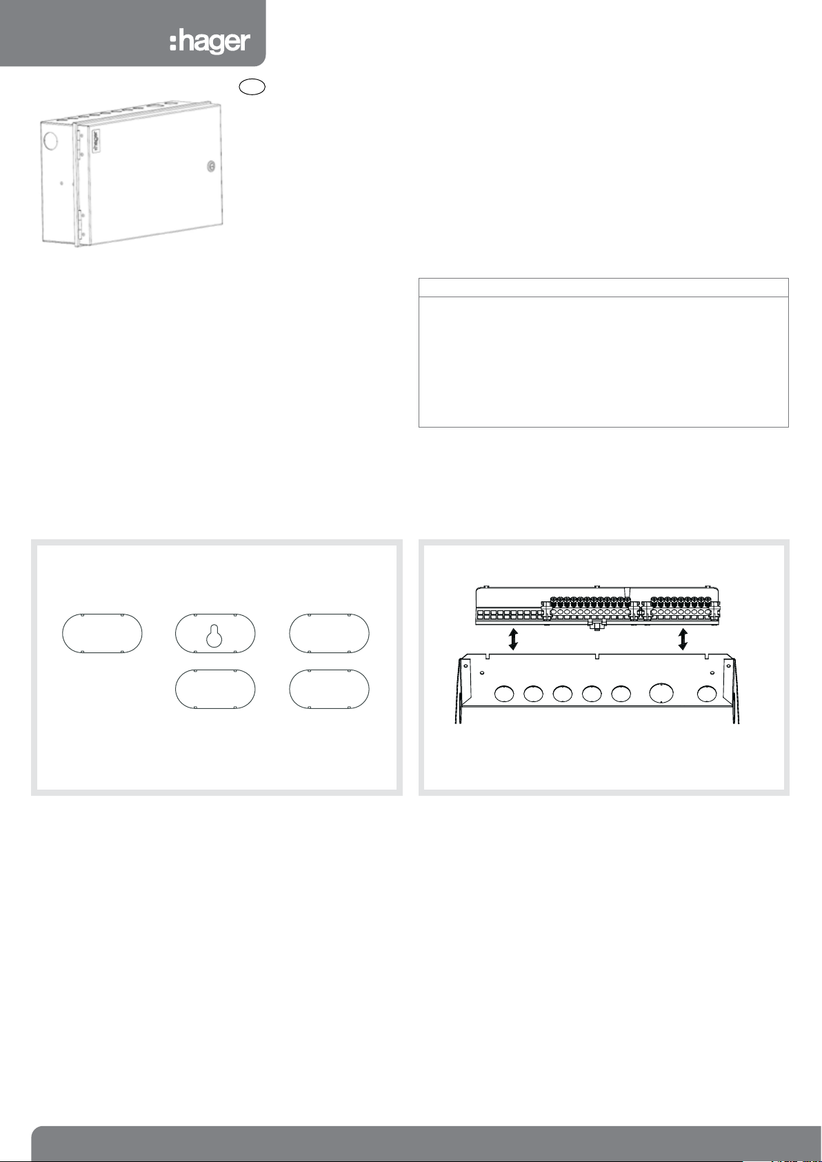
Metal Unit - Removing and replacing the terminal rail for cabling:
Metalclad units are provided with knockouts for standard 20, 25, and
32mm conduit and large rear knockouts.
Note: Only BASEC approved cable should be used
2
to 16mm2 for outgoing cables
1.0mm
up to 35.0mm2 for incoming live cables
Single conductors below 1.5mm² need to be doubled back in the terminal bar.
1
Pull and lift the terminal bar support away from the unit resting the rail
supported by the earth strap. After xing conduit/ cable glands, locate
the rail support and press down.
ZD0651 - Issue 3 03-15
Page 2
Guidance Notes:
The total load must not exceed the rating of the incoming device or the assigned assembly rating (InA) whichever is the lower. Each neutral and earth
connection must correspond numerically to its outgoing way. Additional blanks (ref. JK01B) are available to cover spare ways.
A pack is provided to label this DBO, please consult us for spares or replacements.
Operating Instruction leaet is provided overleaf. This leaet should be left for the end user.
Single conductors below 1.5mm² need to be doubled back in the terminal bar.
DBOs incorporating RCDs in TT systems should incorporate an S type (time Delayed) RCCB, e.g. 100 mA s-type RCCB . Alternatively a main switch with
RCBO protection on all outgoing circuits should be used.
Precautions need to be taken to prevent faults to earth on the supply side of the RCD (as per BS7671 regulation 531.4.1)
IP Ratings:
Cable access into the DBO must maintain the integrity so far as reasonably practicable. In essence, for surfaces accessible after installation, this means
maintaining the requirement for the horizontal top surface of the enclosure to provide a degree of protection of at least IP4X and elsewhere, IP30. For
rear cable access, the minimum number of knockout(s) shall be removed.
IP Code Description
IP2XC Protection against access
IP30 Protection against access with
IP4X A probe of 1mm diameter
with a tool (2.5mm diameter,
100mm long) making contact
with live hazardous parts
a tool (2.5mm diameter, shall
not penetrate)
shall not enter the enclosure
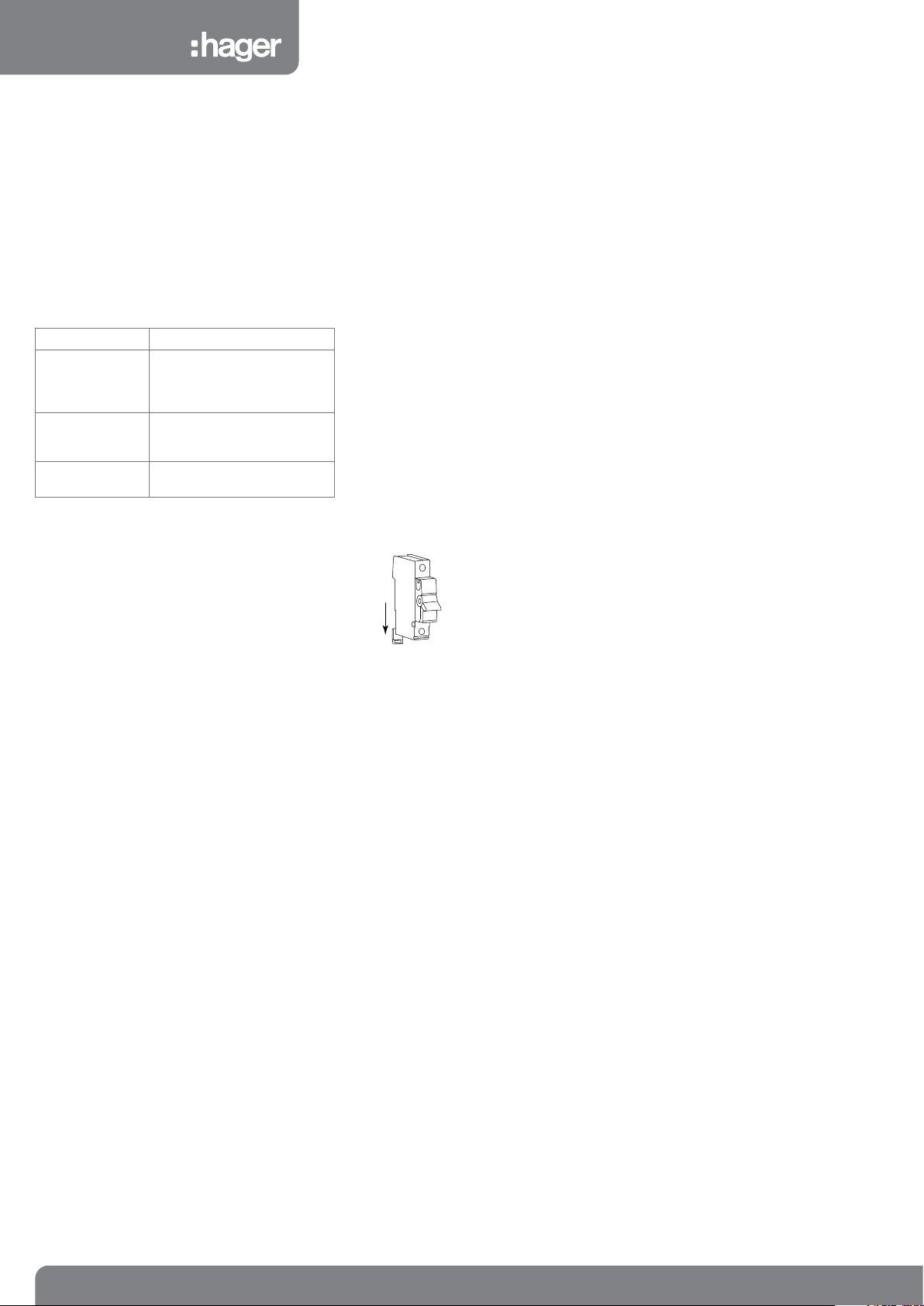
Fitting Hager MCBs and RCBOs:
Only equipment and arrangements specied in Hager’s technical
documentation / catalogue shall be used.
1. Isolate the electrical supply from the DBO.
2. Remove the front cover.
3. Fully slacken the lower terminal of the device.
4. Fully open the bottom device clip (g 1.)
g 1.
Warranty
This distribution board is offered with a 24 month warranty against defective material or manufacture. If a warranty claim is necessary, please call the
technical support number given at the bottom of the page and we will be pleased to help.
For dimensional information and weights please consult the Hager catalogue.
5. Locate the device onto the din rail, and busbar. Ensure that the
busbar tooth is within the device terminal cage.
6. Close the bottom device clip.
7. While holding the device rmly onto the busbar, fully tighten the lower
terminal screw.
8. After tting all outgoing devices and connecting all outgoing cables,
please check the tightness of all cable connections. This should
include all factory made connections, which may have loosened
during installation or transit.
ZD0651 ZD0651
2
Hager Technical Help Line: 01952 675 689
Hager Technical Fax: 01952 675 557
Website: www.hager.co.uk
E-mail us: info@hager.co.uk
ZD0651 - Issue 3 03-15
Page 3

Interface characteristics
Rated & operational voltage (Un / Ue)
230V a.c. 50Hz
Rated insulation voltage (Ui)
320V a.c. 50Hz
Rated impulse withstand voltage (Uimp)
4kV
Rated current of the Assembly (InA)
100A, 63A
Note: Dependent upon rating of main incoming device
Rated current of an Outgoing circuit (Inc)
MCB 6A - 63A (marked rated current on device)
RCBO 6A - 50A (marked rated current on device)
Rated conditional short-circuit current of the ASSEMBLY (Icc)
Annex ZB: 16 kA rms at 250V, power factor 0.6 with equipment and arrangements specied in Hager’s technical documentation /
catalogue.
Protection against electric shock
Consumer unit shall be installed in an electrical system conforming to the current edition of IEC 60364 / BS 7671
Rated diversity factor (RDF) / Values of assumed loading
1way = 1.0
2way – 3way = 0.8
4way – 5way = 0.7
6way – 9way = 0.6
10way and above = 0.5
Rated frequency (fn)
50 Hz
Pollution degree
2
Types of system earthing for which the ASSEMBLY is designed
TNC-S, TN-S when installed in an electrical installation complying with BS 7671
Hager recommends for TT systems a 100A type S time delayed RCCB or a main switch with RCBO protection only on all outgoing circuits.
Indoor use only
Stationary ASSEMBLY
Degree of protection
IP2XC with door open and full compliment of outgoing devices and or blanks tted.
IP30 with door closed and full compliment of outgoing devices and or blanks tted.
Note: Where cables are installed through top wall of enclosure, gaps of IP4X to be maintained.
Intended use
Intended for use in domestic (residential) or similar premises.
Electromagnetic compatibility (EMC) classification
EMC Environment B
External design
JKA: Wall-mounted, surface type, enclosed assembly.
Mechanical impact protection
IK 05
The type of construction
Fixed parts
Type A DBO (Distribution board for use by ordinary persons)
Rated current of outgoing unit (Inc)
RCCB 40A -100A (marked rated current on device)
Note: RDF only applies to continuously and simultaneously loaded
circuits.
In principle, this means adjacent circuit-breakers having a load
‘on’ time exceeding 30 minutes or where a load not exceeding 30
minutes has an ‘off’ time less than the ‘on’ time, will need to have
the rated diversity factor applied as indicated.
3
ZD0651 - Issue 3 03-15
Page 4

START
T
B
T
ON
ON ON
T
Blank RCCB RCBO (two module) MCB RCBO Switch
(one module)
Use circuit as
normal
YES
NO
Does device
stay ON?
NO
Does device
supply socket
outlets
YES
Try & reset device once
MCB
or
RCBO
MCB
tripped
What device
is it?
RCCB
Try & reset device once
Use circuit as
Does device
all MCBs devices
Reset RCCB
normal
YES
stay ON?
NO
Turn OFF
Unplug all
appliances from
circuit and reset
device / replace fuse*
Unplug faulty
appliance until
repaired. Reset device.
Other appliances may
NO
Does device
stay ON?
Plug in & switch on
YES
appliances one at a time
until device trips / blows,
identifying faulty appliance
D
Insulated
Dimensions
(mm)
Enclosure Size
8 12 16 22 2x12 2x16 2x22 3x22
A 254 326 398 505 326 398 505 505
B 236 236 236 236 472 472 472 708
C N/A N/A N/A N/A N/A N/A N/A N/A
D 125 125 125 125 125 125 125 125
A
be used
NO
Does device
stay ON?
Turn ON MCBs
devices one at a time
until RCCB trips again,
identifying faulty circuit
YES
4
ZD0651 - Issue 3 03-15
 Loading...