

Page 1
Installation
instruct
ions
ZD0695
Invicta 3 Panelboard
JF8**B
Notice d’instructions
Bedienungsanleitung
Instrucciones de uso
Instruções
Bruksanvisning
Gebruiksaanwijzing
Page 2
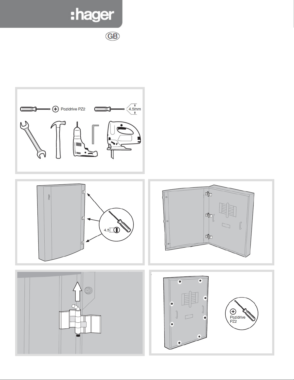
ZD0695
Fixing points with central keyhole
Page 3
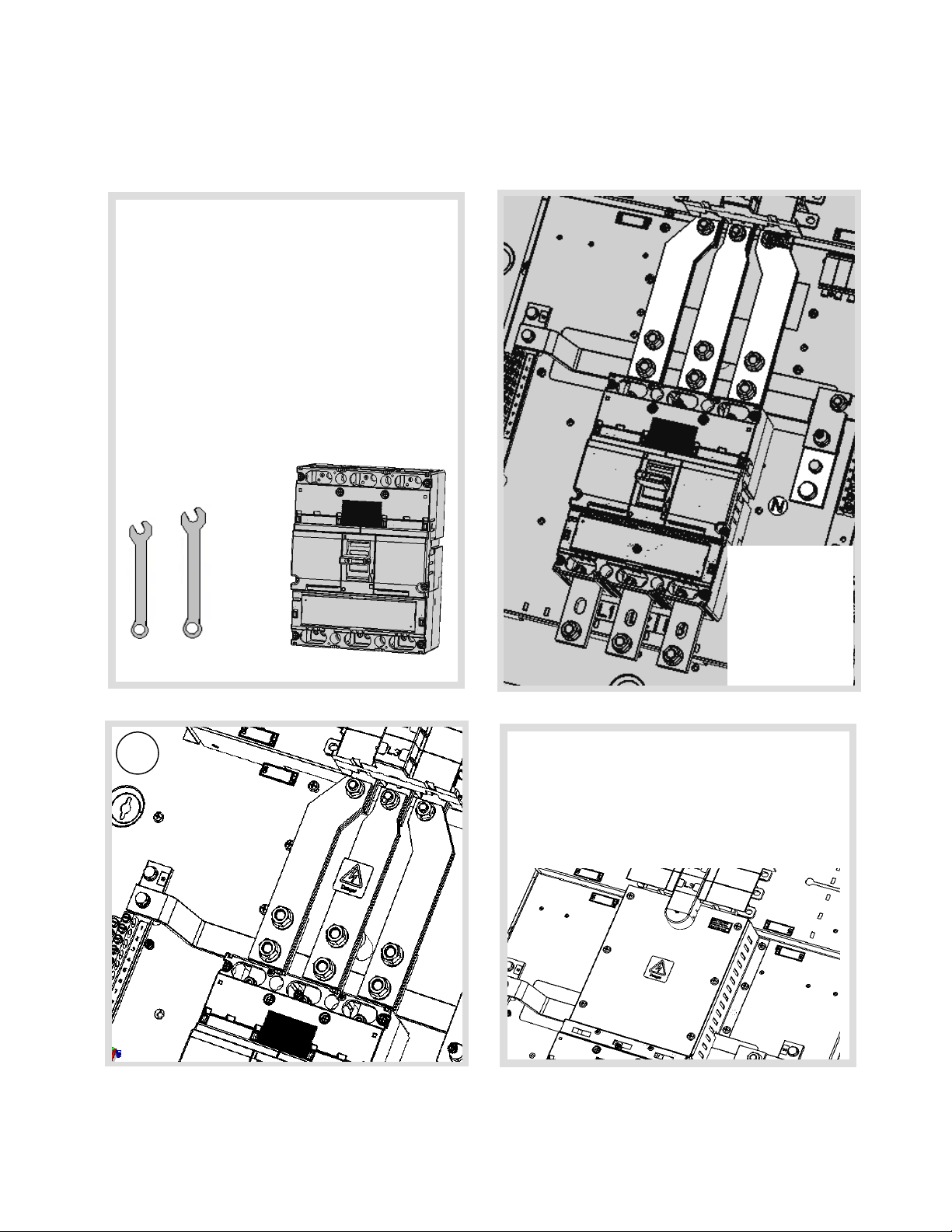
ZD0695
1 2
B
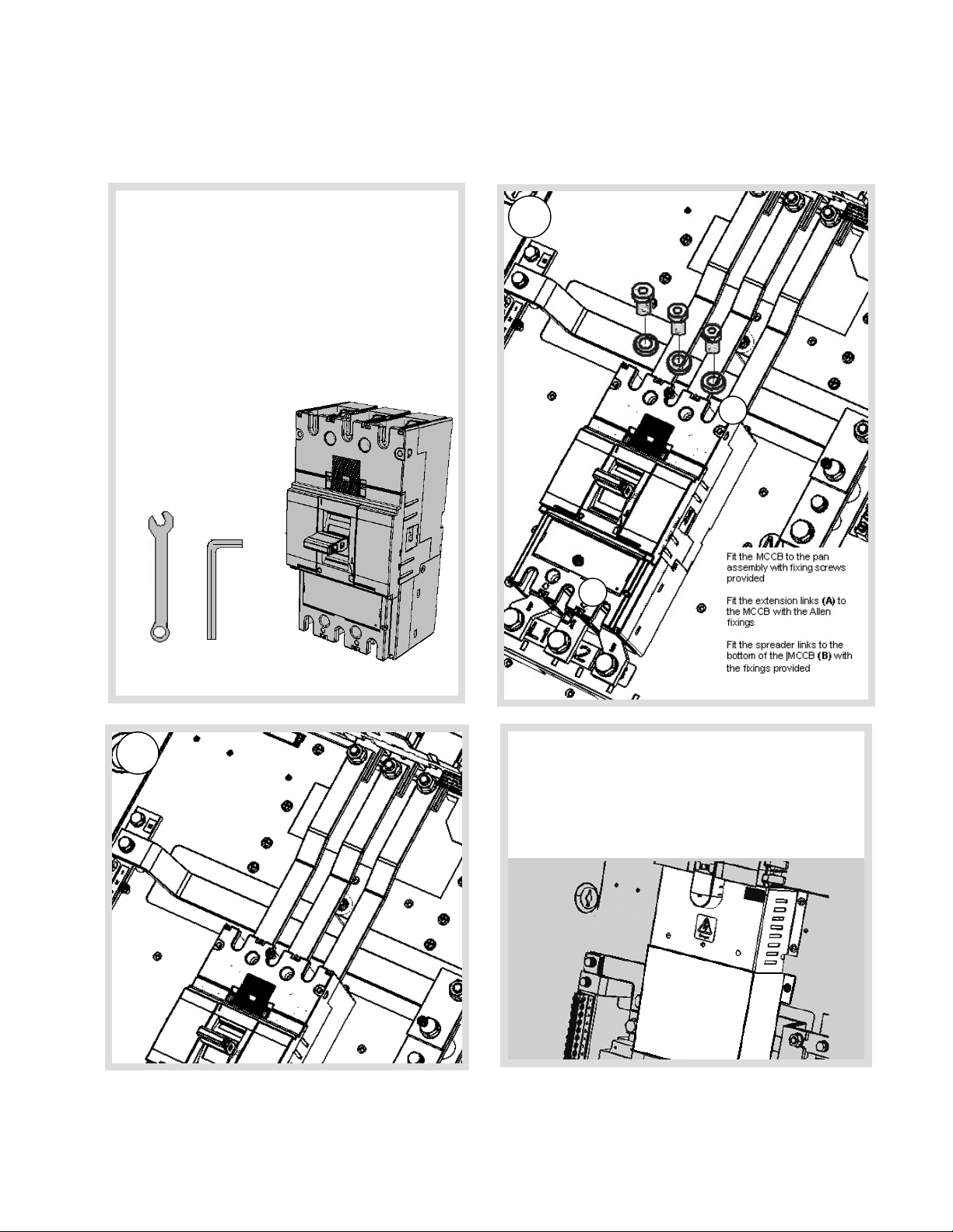
JF8 3 Pole 400A MCCB incomer kit
400A Incomer kits contain:
· 3 x Phas e extension links
· 3 x spreader links
· 6 x Phas e link Allen fixing bolts and washers (M10)
· 4 x Long fixing screws
· 1 x MCCB
· 3 x M8 120mm Lug
· Terminal covers
Ensure terminal shrouds are
removed before fitting.
17 mm A/F
8 mm HEX
A
Connect the extension links to the busbar with the 3 x M10
coach bolts. Hand tighten at this stage.
Now tighten the MCCB fixing screws to secure the MCCB to
the pan ass embly.
Once the MCCB is in place tighten all M10 electrical
connections to 22Nm
Fit the terminal shrouds
Page 4
6mm HEX
13mm A/F
ZD0695
2 1
A
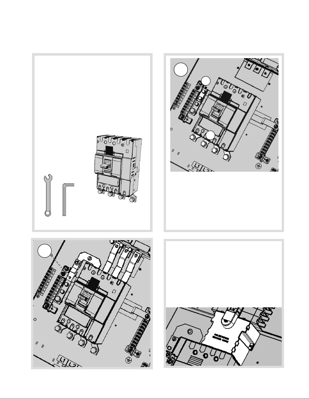
JF8 4 Pole 400A MCCB incomer kit
400A 4 pole incomer kits contain:
· 3 x Line extension links
· 1 x Neutral link
· 4 x spreader links
· 8 x Phase link Allen fixing bolts and washers (M10)
· 4 x Long fixing screws
· 1 x MCCB
· Terminal covers
Ensure terminal shrouds are
removed before fitting.
17 mm A/F
8 mm HE X
Remove the busbar shield. Remove the two M8 bolts that
secure the neutral swing link (A). Replace the bottom M8
bolt.
The top bolt is used to connect the 4 pole neutral link.
The swing link is not required for the 4 pole incomer.
Fit the MCCB to the pan assembly with the fixings provided
Fit the spreader links to the bottom of the |MCCB (B) with
the fixings provided
Connect the extension links to the busbar with the 3 x M10
coach bolts the M8 coach bolts. Hand tighten at this stage.
Connect the neutral link with the M8 coach bolts. Hand
tighten at this stage
Now tighten the MCCB fixing screws to secure the MCCB to
the pan ass embly.
Once the MCCB is in place tighten all M10 electric al
connections to 22Nm. Tighten all M8 connections to 13Nm
Fit the terminal shrouds
B
Page 5
ZD0695
A/F
2
JF8 3 Pole 630A MCCB incomer kit
630A Incomer kits contain:
· 3 x Phas e extension links
· 3 x spreader links
· 6 x Phas e link Allen fixing bolts and washers (M10)
· 4 x Long fixing screws
· 1 x MCCB
· 3 x M8 120mm Lug
· Terminal covers
Ensure terminal shrouds are
removed before fitting.
17mm & 19 mm
Fit the MCCB to the
pan assembly with
the fixing screws
Fit the extension
links (A) to the
MCC B with th e All an
fixings
Connect the extension links to the busbar with the 3 x
M10 coach bolts. Hand tighten at this stage.
Now tighten the MCCB fixing screws to secure the MCCB
to the pan assembly.
Once the MCCB is in place tighten all M10 electrical
connections to 22Nm and M12 to 45-65Nm
Fit the terminal shrouds
Page 6

ZD0695
2 1
A/F
JF8 4 Pole 630A MCCB incomer kit
400A 4 pole incomer kits contain:
· 3 x Line extension links
· 1 x Neutral link
· 4 x spreader links
· 8 x Phas e link Allen fixing bolts and washers (M10)
· 4 x Long fixing screws
· 1 x MCCB
· 4 x M8 120mm Lug
· Terminal covers
Ensure terminal shrouds are
removed before fitting.
12 mm, 17mm & 19 mm
Remove the busbar shield. Remove the M8 bolt (A).
The top bolt is used to connect the 4 pole neutral link.
Fit the MCCB to the pan assembly with the fixings provided
A
B
Connect the extension links to the busbar with the 3 x M10
coach bolts the M8 coach bolts. Hand tighten at this stage.
Connect the neutral link with the M8 coach bolts. Hand
tighten at this stage
Now tighten the MCCB fixing screws to secure the MCCB to
the pan ass embly.
Once the MCCB is in place tighten all M10 electrical
connections to 22Nm and M12 to 45-65Nm. Tighten all M8
connections to 13Nm. Fit the terminal shrouds
Page 7

ZD0695
1
3
2
JF8 4 Pole 630A Switch disconector incomer kit
630A 4 pole inc omer kits contain:
· 3 x Line extension links
· 1 x Neutral link
· 8 x Phas e link fixing bolts and washers (M12)
· 4 x Long M6 fixing screws and washers
· 1 x 630A switch
· 1 x rear terminal shield
· Terminal covers
Ensure terminal shrouds are
removed before fitting.
Remove busbar cover and fit the switch to the pan as sembly
with the M6 fixings provided
Fit the rear terminal shield (A)
Connect the extension links to the busbar with the 3 x M10
coach bolts. Hand tighten at this stage.
Connect the neutral link with the M8 bolts. Hand tighten at
this stage
Now tighten the M6 fixing screws to secure the switch to the
pan assembly.
Once the Switch is in place tighten all M10/M12 electr ic al
connections to 22Nm. tighten the M8 electrical c onnecti ons
A
Page 8

J
F8 3
Pole
direct connect
incomer kit
1
3
2
ZD0695
Direct connect kit includes:
· 3 phase link assembly
· Lower direct connection shield
· Front cover adapter plate
o 3 x nylon pillar
o 1 x direct connect strap
o 3 x M6 bolt, spring washer, flat washer
o 6 x M12 bolt, flat washer, carp nut
o 1 x insulation barrier
o 4 x M6 fixing bolts (f or shield
Remove busbar shield
Place 3 x nylon pillars and hand tighten
Fit the insulation barrier over the nylon pillar
Locate the insulated barrier over the nylon pillars.
Secure used fixings provided
Locate the link sub assembly onto the nylon pillars
Use 3 x M6 bolts and washers to fix the links to the pillars
Tighten all M10 electrical connections to 22Nm
Refit the busbar shield
Use the 4 x M6 fixings to fit the lower direct connection
shield
Page 9

Fitting
Single Pole MCCBs
Fitting
Three
Pole MCCBs
Use the 3 x M10 bolts and washers to fix at busbar
Only equipment and arrangements specified in Hager’s technical documentation / catalogue shall be used.
Single pole MCCB contains:
· 2 x Fixing bolts
· 2 x Spring washers
· 2 x Single fixing plates
· 2 x Double fixing plates
Mount the MCCB on to the busbar finger with the red trip
button f acing inwards. Fix the devic e to the pan
ass em bly using the fixings provided
See single pole instructions for more information
Tighten electrical connections to 6.6Nm
▲
Three pole MCCB contains:
· 2 x Fixing bolts
· 2 x Spring washers
· 2 x Flat washers
Mount the MCCB on to the busbar finger with the red trip
button f acing inwards. Fix the devic e to the pan
ass em bly using the fi xings provid ed.
Use the Auxiliary/Shunt trip accessory channel (▲) to
dress c ables from these accessories
See three pole instructions for more information
Page 10

ZD0695
Achieving Form 3b type 2
on x160 frame MCCB outgoing
P
25mm
25mm Cable
P
Achieving Form 3b type 2
on x250 frame MCCB outgoing
Using HYA021H Terminal cover: Outgoing Devices x160 Frame only (125A)
Cut Out Dimensions are shown below to achieve IPXXB (Form 3b type 2)
2.5mm Cable
4mm Cable
6mm Cable
10mm Cable
&
16mm Cable
15mm
6mm
35mm Cable
&
15mm
13mm (complete inner cut-out wid th)
13mm (complete inner cut-out width)
Using HYA021H Terminal cover: Outgoing Devices x250 Frame (250A)
Cut Out Dimensions for the insert are shown below to achieve IPXXB (Form 3b type 2)
Page 11

ZD0695
Service Conditions
Warranty
JF4 Accessories
Performance Characteristics
ZD0695
Hager distribution boards must only be fitted with Hager
Equipment and arrangements specified in Hager Technical
documents and catalogues
Indoor Use only
Pollution degree: 3
Forms of separation: Form 3b when outgoing shrouds are fitted. A
competent person must always complete a risk assessment and
appropriate test to c onfirm that, the un-shrouded neutral within the
Panelboard is not a hazardous live part. In particular, The
Electricity at Work Regulations 1989 including any amendments
must be complied with.
Maximum Current ( I
JN2*** 250A** 415V a.c. 50Hz
JF4*** 400A** 415V a.c. 50Hz
JF8*** 630A** 415V a.c. 50Hz
** or rating of main incomer whichever is lower
Range of outgoing devices (Inc )
MCCB x160 frame 16 – 125A
MCCB x250 frame 100 – 250A
Main busbar (Icw )
Main Neutral conductor (Icw )
Main protective conductor (Icc )
MCCB BS EN 60947-2
Main board Inc omer kit Outgoing device Conditional rating
JN2 Direct connection 125A MCCB 25kA/ 52.5 kA Pk
JF4 Direct connection 125A MCCB 25kA/ 52.5 kA Pk
JF8 Direct connection 125A MCCB 25kA/ 52.5 kA Pk
JF8 Direct connection 250A MCCB 40kA/ 84 kA Pk
JF8 JF864BSW 125A MCCB 25k A/ 52.5 kA Pk
JF8 JF864BSW 250A MCCB 25k A/ 52.5 kA Pk
IP3X with door closed
IP2XC with door open and compliment of outgoing devices and
blanks fitted.
Suitable for Fixed connection (FF) Forms of Internal Separation 3b
No. of Main Circuits Diversity/ Loading factor
2 & 3 0.9
4 & 5 0.8
6 to 9 inclusive 0.7
10 and above 0.6
ZD0695
)
nA
JN2*** 25kA for 1 sec / 52.5 kA Pk
JF4*** 35kA for 1 sec / 73.5 kA Pk
JF8*** 35kA for 1 s ec / 73.5 kA Pk
JN2*** 15kA for 1 sec / 30 kA Pk
JF4*** 21kA for 1 s ec / 44.1 kA Pk
JF8*** 24kA for 1 s ec / 50.42.5 kA Pk
JN2*** 25kA conditional / 52.5 kA Pk
JF4*** 40kA conditional / 84 kA Pk
JF8*** 50kA conditional / 105 kA Pk
(Icc )
Panelboard to BS EN 61439 -2 (unless otherwise stated)
Ui 690V a.c. 50Hz
Ue 415V a.c. 50Hz
Uimp 6kV
Rated frequency 50Hz
Suitable earthing system TNC-S, TN-S and TT
(Subject to compliance with the relevant regulations in the current
edition of BS 7671)
This distribution board is offered with a 24 month warranty against
defective m at erial or man uf actur e. If a w arr anty clai m is
necessary, please call the technical support number given at the
bottom of the page and we will be pleased to help.
JN2 Incomer kits
JN213BM 125A 3P MCCB INCOMER KIT
JN214BM 125A 4P MCCB INCOMER KIT
JN223BM 250A 3P MCCB INCOMER KIT
JN224BM 250A 4P MCCB INCOMER K IT
JN223BS 250A 3 POLE ISOLATOR INCOMER KIT
JN224BS 250A 4 POLE ISOLATOR INCOMER KIT
JN224BD 250A DIRECT CONNECTION KIT
JN2 Accessories
JN001BP 1P BLANKING PLATE 125A FRAME
JN2PLATE JN ENDPLATE
JN201BA MULTI FUNCT ION DIGITAL METER PACK
JN201BE SMALL DIN RAIL BOX, PLAIN DOOR
JN201BEG SMALL DIN RAIL BOX, GLAZED DOOR
JN203BE LARGE DIN RAIL BOX, PLAIN DOOR
JN203BEG LARGE DIN RAIL BOX, GLAZED DOOR
JN205BE SMALL SPREADER BOX (NO DOOR)
JN205DK DOOR KIT FOR SMALL SPREADER BOX
JN206BE LARGE SPREADER BOX (NO DOOR)
JN206DK DOOR KIT FOR LARGE SPREADER BOX
JF4 Incomer kits
JF443BM 400A 3P MCCB INCO MER KIT
JF444BM 400A 4P MCCB INCO MER KIT
JF443BS 400A 3 POLE ISOLATOR INCOMER KIT
JF444BS 400A 4 POLE ISOLATOR INCOMER KIT
JF444BD 400A DIRECT CONNECTION KIT
JF003BP 3P BLANKING PLATE 250A FRAME
JN001BP 1P BLANKING PLATE 125A FRAME
JFPLATE JF4 & 8 ENDPLATE
JF403BA MULTI FUNCT DIGITAL METER PACK
JF801E SMALL DIN RAIL BOX, PLAIN DOOR
JF801EG SMALL DIN RAIL BOX GLAZED DOOR
JF803E LARGE DIN RAIL BOX, PLAIN DOOR
JF803EG LARGE DIN RAIL BOX, GLAZED DOOR
JF805E SMALL SPREADER BOX (NO DOOR)
JF805DK DOOR KIT FOR SMALL SPREADER BOX
JF806E LARGE SPREADER BO X (NO DOOR)
JF806DK DOOR KIT FOR LARGE SPREADER BOX
JF8 Incomer kits
JF864BSW 630A 4 POLE ISOLATOR INCOMER KIT
JF840BM 400A 3P MCCB INCOMER KIT
JF840BM 400A 4P MCCB INCOMER KIT
JF863BM 630A 3P MCCB INCOMER KIT
JF864BM 630A 4P MCCB INCOMER KIT
JF884BD JF8 DIRECT CONNECTION KIT
JF8 Accessories
JF003BP 3P BLANKING PLATE 250A FRAME
JN001BP 1P BLANKING PLATE 125A FRAME
JF801E SMALL DIN RAIL BOX, PLAIN DOOR
JF801EG SMALL DIN RAIL BOX GLAZED DOOR
JF803BA MULT I FUNCT DIGITAL METER PACK
JF803E LARGE DIN RAIL BOX, PLAIN DOOR
JF803EG LARGE DIN RAIL BOX, GLAZED DOOR
JF805DK DOOR KIT FOR SMALL SPREADER BOX
JF805E SMALL SPREADER BOX (NO DOOR)
JF806DK DOOR KIT FOR LARGE SPREADER BOX
JF806E LARGE SPREADER BOX (NO DOOR)
JFPLATE JF4 & 8 ENDPLATE
Page 12

Panel board circuit designation chart
D.B No: Voltage: Supplied From:
Supply cable mm: Incoming Isolator: Ze: P.S.C.
CIR AMPS TYPE CABLE MM C.P.C MM LOCAT ION DESCRIPTION
ZD0695
Page 13

D.B No: Voltage: Supplied From:
Supply cable mm: Incoming Isolator: Ze: P.S.C.
CIR AMPS TYPE CABLE MM C.P.C MM LOCAT ION DESCRIPTION
ZD0695
Page 14

Hager Ltd.
Hortonwood 50
Telford
Shropshire
TF1 7FT
National Sales Hotline 01952 675612
National Tech Support helpline 01952 675689
ZD0695
 Loading...