

Page 1
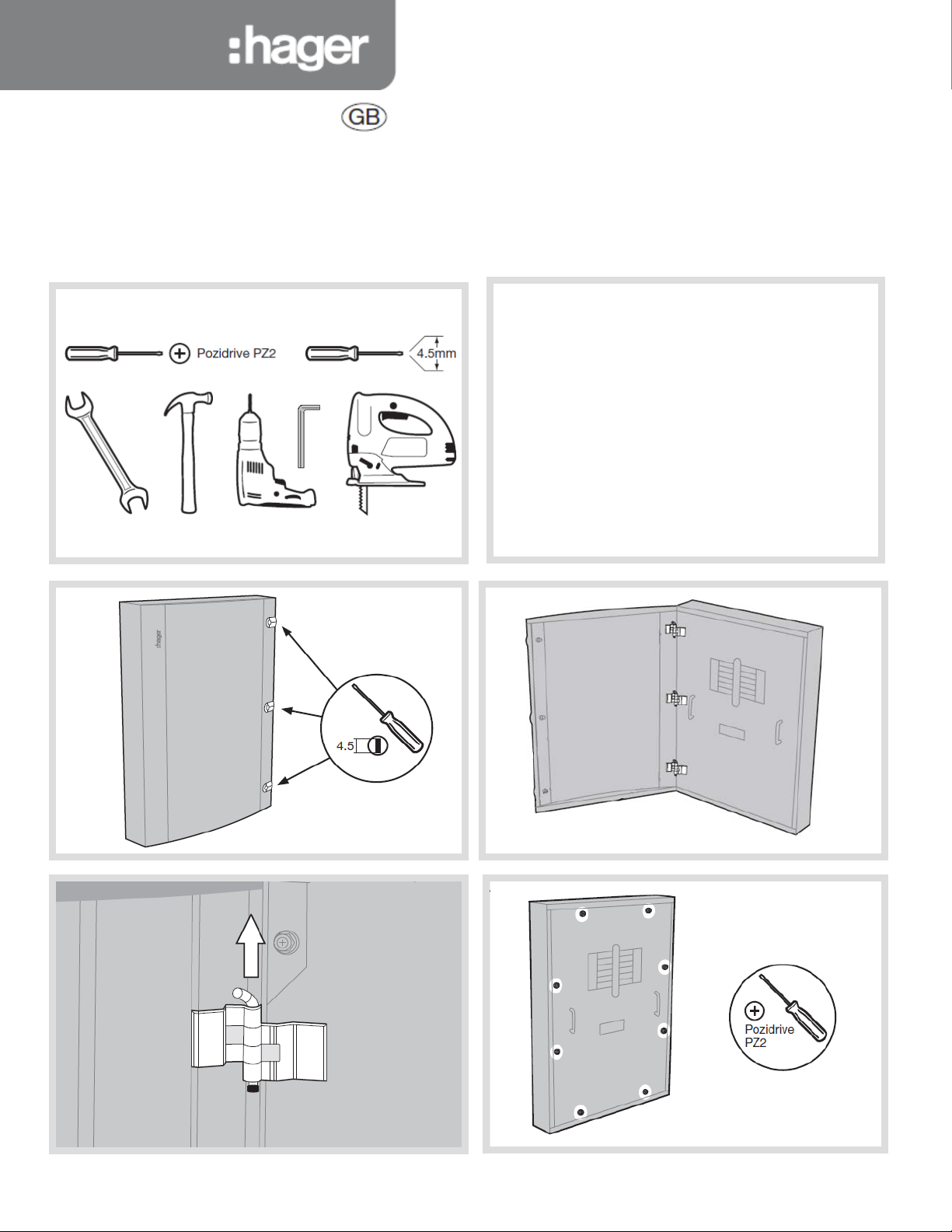
Installation instructions
JF8**B(G)
JF6**B(G)
Invicta 3 Panelboard
All product(s) must be installed by a suitably competent
Notice d’instructions
Bedienungsanleitung
Instrucciones de uso
Instruções
electrician giving consideration to their intended use and in
accordance with the current edition of BS 7671 (IET Wiring
Regulations).
ctricity at Work regulations and the Health and Safety at
The Ele
Work Act shall be complied with.
Only equipment and arrangements specified in Hager’s technical
documentation / catalogue shall be used
l in the vertical plane only.
Instal
Notice:
To prevent potential overheating from loose connections the
installer shall check connections are tightened to the torque levels
stated in these instructions prior to energising this board. This
check should include factory made connections which may have
loosened in transit or as a result of.
Bruksanvisning
Gebruiksaanwijzing
ZD0741
Issue 5
Page 2

Fixing points with central keyhole
ZD0741
Issue 5
Page 3

400A Incomer kits contain:
JF6/JF8 3 Pole 400A MCCB incomer kit
1
2
Connect the extension links to the busbar with the 3 x M10
17 mm A/F
8 mm HEX
A
B
hase extension links
• 3 x P
preader links
• 3 x s
• 6 x Phase link Allen fixing bolts and washers (M10)
• 4 x Long f
• 1 x
• 3 x M
• Ter
Ensure terminal shrouds are
removed before fitting.
ixing screws
MCCB
8 120mm Lug
minal covers
coach bolts. Hand tighten at this stage.
Now tighten the MCCB fixing screws to secure the MCCB to
the pan assembly.
ZD0741 Issue 5
e the MCCB is in place tighten all M10 electrical
Onc
connections to 22Nm
Fit the terminal shrouds
Page 4

400A 4 pole incomer kits contain:
6mm HEX
13mm A/F
JF6/JF8 4 Pole 400A MCCB incomer kit
2
1
B
A
17 mm A/F
8 mm HEX
• 3 x Line extension links
• 2 x Neutral links
• 4 x spreader links
• 8 x Phase link Allen fixing bolts and washers (M10)
• 4 x Long fixing screws
• 1 x MCCB
• Terminal covers
Ensure terminal shrouds are
removed before fitting.
Remov
e the busbar shield. Remove the two M8 bolts that
secure the neutral swing link (A). Replace the bottom M8
bolt.
The top bolt is used to connect the 4 pole neutral link.
The swing link is not required for the 4 pole incomer.
Fit the MCCB to the pan assembly with the fixings provided
Fit
the spreader links to the bottom of the |MCCB (B) with
the fixings provided
Connect the extension links to the busbar with the 3 x M10
coach bolts the M8 coach bolts. Hand tighten at this stage.
Connect the neutral links with the M8 coach bolts. Hand
tighten at this stage
Now tighten the MCCB fixing screws to secure the MCCB to
the pan assembly.
Once the MCCB is in place tighten all M10 electrical
connections to 22Nm. Tighten all M8 connections to 13Nm
Fit the terminal shrouds
ZD0741 Issue 5
Page 5

630A Incomer kits contain:
Connect the extension links to the busbar with the 3 x
17mm & 19 mm
A/F
JF6/JF8 3 Pole 630A MCCB incomer kit
2
Fit the MCCB to the
Phase extension links
• 3 x
spreader links
• 3 x
• 6 x Phase link Allen fixing bolts and washers (M10)
• 4 x
Long fixing screws
• 1
x MCCB
M8 120mm Lug
• 3 x
erminal covers
• T
Ensure terminal shrouds are
removed before fitting.
pan assembly with
the fixing screws
Fit the extension
links (A) to the
MCCB with the Allan
fixings
ZD0741 Issue 5
M10 coach bolts. Hand tighten at this stage.
Now tighten the MCCB fixing screws to secure the MCCB
to the pan assembly.
nce the MCCB is in place tighten all M10 electrical
O
connections to 22Nm and M12 to 45-65Nm
Fit the terminal shrouds
Page 6

400A 4 pole incomer kits contain:
JF6/JF8 4 Pole 630A MCCB incomer kit
12 mm, 17mm & 19 mm
A/F
• 3 x Line extension links
• 2 x Neutral links
• 4 x spreader links
• 8 x Phase link Allen fixing bolts and washers (M10)
• 4 x Long fixing screws
• 1 x MCCB
• 4 x M8 120mm Lug
• Terminal covers
Ensure
terminal shrouds are
removed before fitting.
Remove the busbar shield.
Fit the MCCB to the pan assembly with the fixings provided
Connect the extension links to the busbar with the 3 x M10
coach bolts the M8 coach bolts. Hand tighten at this stage.
Connect the 2 neutral links with the M8 coach bolts, making
sure they are fitted under the Neutral phase of the MCCB.
Hand tighten at this stage.
Now tighten the MCCB fixing screws to secure the MCCB to
the pan assembly.
Once the MCCB is in place tighten all M10 electrical
connections to 22Nm and M12 to 45-65Nm. Tighten all M8
connections to 13Nm. Fit the terminal shrouds
ZD0741 Issue 5
Page 7

630A 4 pole incomer kits contain:
JF6/JF8 4 Pole 630A Switch disconector incomer kit
132
A
• 3 x Line extension links
• 2 x Neutral links
• 8 x Phase link fixing bolts and washers (M12)
• 4 x Long M6 fixing screws and washers
• 1 x 630A switch
• 1 x rear terminal shield
• T erminal covers
Ensure terminal shrouds are
removed before fitting.
Remove busbar cover and fit the switch to the pan assembly
with the M6 fixings provided
Fit the rear terminal shield (A)
Connect the extension links to the busbar with the 3 x M10
coach bolts. Hand tighten at this stage.
Connect the neutral links with the M8 bolts. Hand tighten at
this stage
Now tighten the M6 fixing screws to secure the switch to the
pan assembly.
Once the Switch is in place tighten all M10/M12 electrical
connections to 22Nm. tighten the M8 electrical connections
to 13Nm. Fit the cover plate to the front cover.
ZD0741 Issue 5
Page 8

Direct connect kit includes:
1
3
2
• 3 phase link assembly
• Lower direct connection shield
• Front cover adapter plate
o 3 x nylon pillar
o 1 x direct connect strap
o 3 x M6 bolt, spring washer, flat washer
o 6 x M12 bolt, flat washer, carp nut
o 1 x insulation barrier
o 4 x M6 fixing bolts (for shield
Remove busbar shield
Pl
ace 3 x nylon pillars and hand tighten
Locate the insulated barrier over the nylon pillars.
Sec
Locat
Us
ure used fixings provided
e the link sub assembly onto the nylon pillars
e 3 x M6 bolts and washers to fix the links to the pillars
Fi
t the insulation barrier over the nylon pillar
ghten all M10 electrical connections to 22Nm
Ti
Refit the busbar shield
Use the 4 x M6 fixings to fit the lower direct connection
shield
Use the 3 x M10 bolts and washers to fix at busbar
ZD0741 Issue 5
Page 9

Fitting Single Pole MCCBs
Fitting Three Pole MCCBs
Tighten electrical connections to 6.6Nm
▲
Only equipment and arrangements specif i ed in Hager’s technical documentation / catalogue shall be used.
Single pole MCCB contains:
• 2 x F
ixing bolts
• 2 x Spring washers
• 2 x Single fixing plates
• 2 x Double fixing plates
Mount
the MCCB on to the busbar finger with the red trip
button facing inwards. Fix the device to the pan
assembly using the fixings provided
single pole instructions for more information
See
ghten electrical connections to 6.6Nm
Ti
Three pole MCCB contains:
• 2 x F
ixing bolts
• 2 x Spring washers
• 2 x Flat washers
the MCCB on to the busbar finger with the red trip
Mount
button facing inwards. Fix the device to the pan
assembly using the fixings provided.
e the Auxiliary/Shunt trip accessory channel (
Us
dress cables from these accessories
hree pole instructions for more information
See t
▲) to
ZD0741 Issue 5
Page 10

Achieving Form 3b type 2 on x160 frame MCCB outgoing
Using HYA021H Terminal cover: Outgoing Devices x160 Frame only (125A)
Cut Out Dimensions are shown below to achieve IPXXB (Form 3b type 2)
15mm
6mm
2.5mm Cable
4mm Cable
6mm Cable
13mm (complete inner cut
-out width)
10mm Cable
&
16mm Cable
15mm
25mm
25mm Cable
&
35mm Cable
Achieving Form 3b type 2 on x250 frame MCCB outgoing
Cut Out Dimensions for the insert are shown below to achieve IPXXB (Fo rm 3b ty pe 2)
Using HYA021H Terminal cover: Outgoing Devices x250 Frame (250A)
ZD0741 Issue 5
Page 11

ZD0695
Service Conditions
Hager distribution boards must only be fitted with Hager Equipment and
Warranty
arrangements specified in Hager Technical documents and catalogues.
Indoor Use Only
Pollution degree: 3
Forms of separation: Form 3b when outgoing shrouds are fitted. A
competent person must always complete a risk assessment and appropriate
test to confirm that, the un-shrouded neutral within the Panelboard is not a
hazardous live part. In parti cular, The Electricit y at Work Regulations 1989
including any amendments must be complied with.
Maxim
JN2** 250A** 415 a.c. 50Hz
JF4** 400A** 415 a.c. 50Hz
JF6**/JF8** 630A** 415 a.c. 50Hz
** or rating of main incomer whichever is lower
Range of outgoing devices (I
MCCB x160 frame 16 – 125A
MCCB x250 frame 100 – 250A
Main b
Main Neutral conductor (I
Main protective conductor (I
MCCB BS EN 60
Main board Incomer Kit Outgoing device Conditional rating (Icc)
JN2 Direct connection 125A MCCB 25kA / 52.5 kA Pk
JF4 Direct connection 125A MCCB 25kA / 52.5 kA Pk
JF6/JF8 Direct connec tion 125A MCCB 25kA / 52.5 kA Pk
JN6/JF8 Direct connection 250A MCCB 40kA / 84 kA Pk
JN6/JF8 JF864BSW 125A MCCB 25kA / 52.5 kA Pk
JN6/JF8 JF864BSW 250A MCCB 25kA / 52.5 kA Pk
IP3X
IP2X with door open and compliment of outgoing devices and blanks fitted.
Suitable for Fixed Connection (FF) Forms of Internal Separation 3b
No. of Main Circuits Diversity/Loading Factor
2 & 3 0.9
4 & 5 0.8
6 to 9 inclusive 0.7
10 and abo
Performance Characteristics
Panelboard to BS EN 61439-2 (unless st ate d oth er wis e)
Ui 690V a.c. 50Hz
Ue 415V a.c. 50Hz
Uimp 6kV
Rated F
Suitabl
(Subject to compliance with relevant regulations in the current edition of BS
7671)
ZD0695
um Current (l
usbar (I
JN2** 25kA for 1 sec / 52.5 kA Pk
JF4** 35kA for 1 sec / 73.5 kA Pk
JF6**/JF8** 35kA for 1 sec / 52.5 kA Pk
JN2** 15kA for 1 sec / 30 kA Pk
JF4** 21kA for 1 sec / 44.1 kA Pk
JF6**/JF8** 24kA for 1 sec / 50.42.5 kA Pk
JN2** 25kA conditional / 52.5 kA Pk
JF4** 40kA conditional / 84 kA Pk
JF6**/JF8** 50kA conditional / 105 kA Pk
with door closed
ve 0.6
requency 50Hz
e earthing system TNC-S, TN-S and TT
)
nA
947-2
This distribution boa rd is off er ed wit h a 24 mo nth war ra nty against defective
material or manufacture. If a warranty claim is necessary, please call the
technical support numb er gi ve n at the bottom of the page and we will be
pleased to help.
JN2 Incomer kits
JN213BM
JN214BM
JN223BM
JN224BM
JN223BS
JN224BS
JN224BD
JN2 Accessories
)
nc
)
cw
)
cw
)
cc
JN001BP
JN2PLATE
JN201BA
JN201BE
JN201BEG
JN203BE
JN203BEG
JN205BE
JN205DK
JN206BE
JN206DK
JF4 Incomer Kits
JF443BM
JF444BM
JF443BS
JF444BS
JF444BD
JF4 Accessories
JF003BP
JN001BP
JFPLATE
F403BA
J
JF801E
JF801EG
JF803E
JF803EG
JF805E
JF805DK
F806E
J
JF806DK
125A 3P MCCB Incomer Kit
125A 4P MCCB Incomer Kit
250A 3P MCCB Incomer Kit
250A 4P MCCB Incomer Kit
250A 3 POLE Isolator Incomer Kit
250A 4 POLE Isolator Incomer Kit
250A Direct Connection Kit
1P BLANKING PLATE 125A FRAME
JN ENDPLATE
MF Digital Meter Pack (Pulsed)
SMALL DIN RAIL BOX, PLAIN D OOR
SMALL DIN RAIL BOX, GLAZED DOOR
LARGE DIN RAIL BOX, PLAIN DOOR
LARGE DIN RAIL BOX, GLAZED DOOR
SMALL SPREADER BOX (NO DOOR)
DOOR KIT FOR SMALL SPREADER BOX
LARGE SPREADER BOX (NO DOOR)
DOOR KIT FOR LARGE SPREADER BOX
400A 3P MCCB Incomer Kit
400A 4P MCCB Incomer Kit
400A
3 POLE Isolator Incomer Kit
400A 4 POLE Isolator Incomer Kit 400A
Direct Connection Kit
3P BLANKING PLATE 250A FRAME
NKING PLATE 125A FRAME
1P BLA
JF4 & 8 ENDPLATE
MULTI FUNCT DIGITAL METER PACK
SMALL DIN RAIL BOX, PLAIN DOOR
S
MALL DIN RAIL BOX GLAZED DOOR
LARGE DIN RAIL BOX, PLAIN DOOR
LARGE DIN RAIL BOX, GLAZED DOOR
SMALL SPREADER BOX (NO DOOR)
DOOR KIT FOR S
LARGE SPREADER BOX (NO DOOR)
DOOR
KIT FOR LARGE SPREADER BOX
MALL SPREADER BOX
JF6/JF8 Incomer Kits
JF864BSW 630A 4 POLE Isolator Incomer Kit
JF843BM 400A 3P MCCB Incomer Kit
JF844BM 400A 4P MCCB Incomer Kit
JF863BM 630A 3P MCCB Incomer Kit
JF864BM 630A 4P MCCB Incomer Kit
JF884BD JF8 Direct Connection Kit
JF6/JF8 Accessories
JF003BP
JN001BP
JFPLATE
JF801E
F801EG
J
JF803BA
JF803E
JF803EG
JF805DK
JF805E
F806E
J
JF806DK
3P BLANKING PLATE 250A FRAME
1P BLANKING PLATE 1
JF4 & 8 ENDPLATE
SMALL DIN RAIL BOX, PLAIN DOOR
SMALL DIN RAIL BOX GLAZED DOOR
MULTI FUNCT DIGITAL METER PACK
LARGE DIN RAIL BOX, PLAIN DOOR
LARGE DIN RAIL BOX, GLAZED DOOR
DOOR KIT FOR SMALL SPREADER BOX
SMALL SPREADER BOX (NO DOOR)
LARGE SPREADER BOX (NO DOOR)
DOOR KIT
FOR LARGE SPREADER BOX
25A FRAME
ZD0741
Issue 5
Page 12

CIR
AMPS
TYPE
CABLE MM
C.P.C MM
LOCATION DESCRIPTION
Panel board circuit designation chart
D.B No: Voltage: Supplied From:
Supply cable mm: Incoming Isolator: Ze: P.S.C.
ZD0741 Issue 5
Page 13

D.B No: Voltage: Supplied From:
CIR
AMPS
TYPE
CABLE MM
C.P.C MM
LOCATION DESCRIPTION
Supply cable mm: Incoming Isolator: Ze: P.S.C.
ZD0741 Issue 5
Page 14

Hager Ltd.
Hortonwood 50
Telford
Shropshire
TF1 7FT
National Sales Hotline 01952 675612
National Tech Support
675689
ZD0741 issue 5
helpline 01952
 Loading...