

Page 1
6LE001602Bc
HTG410H / HTG411H
z
a
e
m
t
r
i
s
Multi - energy data logger & server
Concentrateur et serveur
de données multi - énergies
Energiemonitoringserver
Serwer monitoringu energii
Servidor & concentrador
Multi-energia
Concentrador y servidor de datos
multimedida
Multi - energie datalogger & server
Multi - energi datalogger & server
z Operating manuel via internet
a Manuel utilisateur via internet
e Bedienungsanleitung via internet
m Instrukcja obsługi (Internet)
t Manual de instalação e operação
via internet
r Guía online de instalación y
funcionamiento
i Installatiehandleiding en
gebruikershandleiding via internet
s Installationsguide och drift manuel
via internet
http://hgr.io/r/htg410h
http://hgr.io/r/htg411h
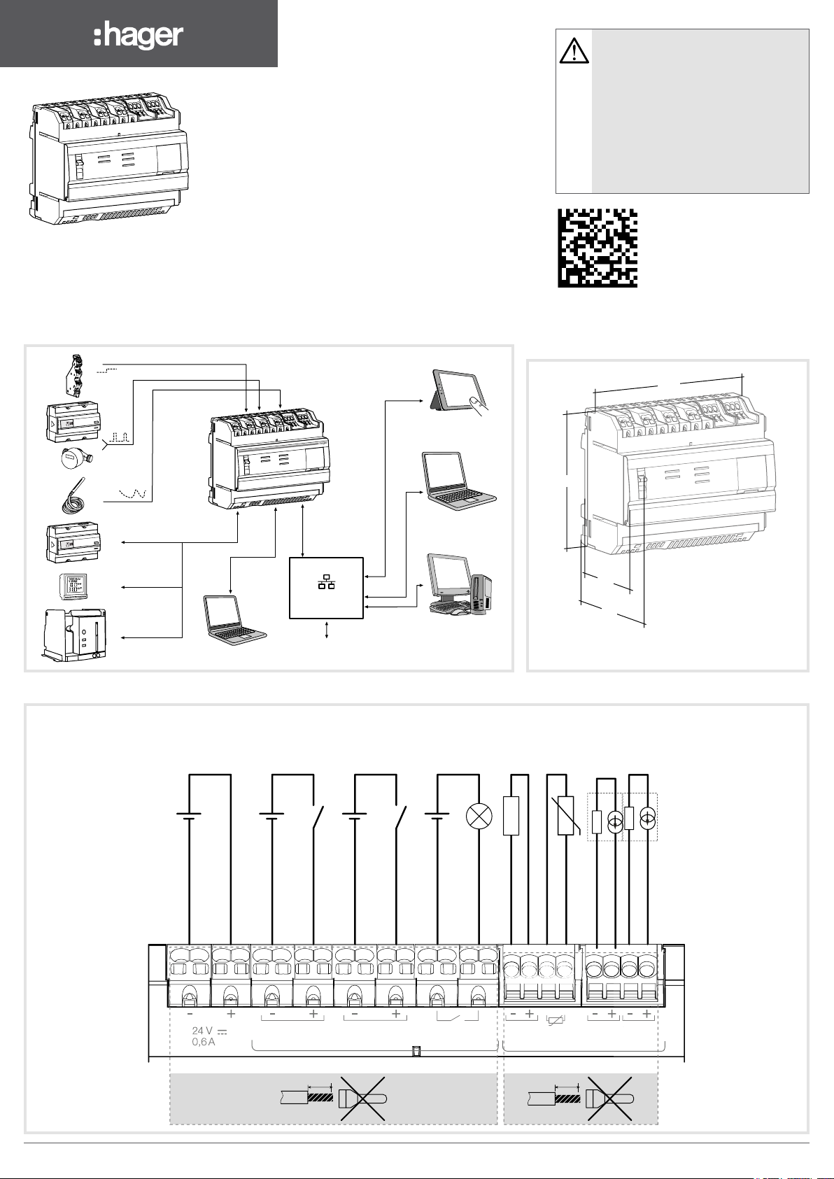
Interface / Interface / Interface / Interfejsy komunikacyjne / Interface /
Interfaz / Interface / Gränssnitt
Dimensions / Dimensions / Abmessungen /
Wymiary / Dimensões / Dimensiones /
Afmetingen / Mått
107
HTG410H
T°
Modbus RTU
90
60
Setup
Router / Switch
INTERNET
67
Dimensions in mm / Dimensions en mm / Abmessungen in mm /
Wymiary w mm / Dimensões em mm / Dimensiones en mm /
Afmetingen in mm / Mått i mm
Connection / Raccordement / Anschluss / Podłączenie / Ligações / Conexión / Aansluiting / Förbindelse
24 V s
TBTS, SELV
(+/- 10 %)
15 to 27 V s
TBTS, SELV
0,4 V A
100 m max
Pulse > 30ms
15 to 27 V s
TBTS, SELV
0,4 V A
100 m max
Pulse > 30ms
5 to 30 V s/v
TBTS, SELV
10 mA to 3 A
resistive
10 m max
>
_ 1 kΩ
10 m max
T°
3 m max
Sensor
10 m max
24 V (-)
24 V (+)
Digital input 1 (-)
Digital input 1 (+)
Input 1
10 mm
0,75 - 2,5 mm
Digital input 2 (-)
Input 2
2
Digital output
Digital input 2 (+)
Output
0 - 10 V output (-)
Digital output
Output
0-10
Digital
4 - 20 mA input (-)
PT100 input
0 - 10 V output (+)
Input
PT100
V4-20 mA
0,2 - 1,5 mm
Input 1 Input 2
8 mm
2
4 - 20 mA input (+)
4 - 20 mA input (-)
4 - 20 mA input (+)
Analog
6LE001602Bc1
Page 2
OO
tt
ll
Z
The HTG410H is a multi-energy data logger
and server. The HTG411H version is delivered
additionally with a 4GB micro SD card. It is
intended to configure systems and products,
collect, store and time stamp information for
connected products. It processes this information
and monitors the quality of the electrical distribution
and makes it available to the user through an
embedded webserver. This product is accessible
from the Internet network.
Prerequisite for installation:
Equipment:
- a computer with internet browser
(Chrome recommended),
- an RJ45 Ethernet cable.
In case of an extended Ethernet network:
- an Ethernet network socket,
- product name on the network,
- a static or dynamic IP address,
- the network mask.
This device is to be installed only by a
professional electrician tter according to
local applicable installation standards.
Do not install this module outside the
building.
Power supply over Ethernet (PoE)
prohibited.
In "Setup ON" mode, the HTG410H
activates its DHCP server on "Setup Ethernet 1" port.
Installation
The HTG410H / HTG411H must be tted on a DIN
rail.
Implementation
1. Connect the inputs / outputs on the HTG410H /
HTG411H terminal block.
2. Connect the Modbus and Ethernet networks as
appropriate.
3. Enable 120 Ω termination resistor (selector (2) to
set to «ON») if the product is tted at the end of the
Modbus network.
4. Check that the selector «Setup» (1) is in «OFF»
position.
5. Connect the 24 V s power supply (SELV).
First conguration
1. Start the software update:
a) download the latest software version from http://
hgr.io/r/htg410h or http://hgr.io/r/htg411h
b) unzip the downloaded le
c) read the le «readme.txt»
2. Connect the computer to the RJ45
«Setup - Ehernet 1» connector of HTG410H /
HTG411H using the Ethernet cable.
3. Turn switch «Setup» (1) in «ON» position.
4. Perform a reset by switching the power
supply off and again on.
5. Activate the Web browser on the computer.
6. Enter: url : https://192.168.0.1
7. Setting the HTG410H / HTG411H, refer to the user
login : admin
password : admin
guide, downloadable from http://hgr.io/r/htg410h
or http://hgr.io/r/htg411h website or with the
Datamatrix scanning.
Technical characteristics
External safety extra low
voltage power supply
Typical consumption
Ethernet network
com munication
Modbus network
com munication
Operating temperature
Storage temperature
Humidity storage
Binary digital input 1 and 2
Analog input
1 and 2
4 - 20 mA
PT 100 input
Binary digital output
Number of relay cycles
Analog output
Power supply, digital inputs,
digital output connection
Analog inputs, analog
output connection
Degree of protection
Weight
Maximum operating altitude
Micro SD card
USB port 1
(front face)
USB port 2
(under the product)
*: The use of product at the maximal temperature can reduce its life expectancy.
0 - 10 V Min impedance
Ethernet - TCP / IP -
RJ45 / 100 base - T /
RS485 Modbus RJ45
95% max HR at 55°C
Input impedance
EN 60751 compliance
5 to 30 V s / v 10 mA to 3 A
resistive dry contact
standard connector
standard connector
24 V s
(SELV)
+/- 10 %
7 VA
IEEE 802.3
-25° to +70°C*
-55° to +85°C
15 to 27 V
<300 Ohms
2-wire probe -
100000
>= 1 kOhms
0.75 - 2.5 mm²
0.2 - 1.5 mm²
IP 20
290 g
2 000 m
Class 10
USB 2.0 Type A
USB 2.0 Type A
s
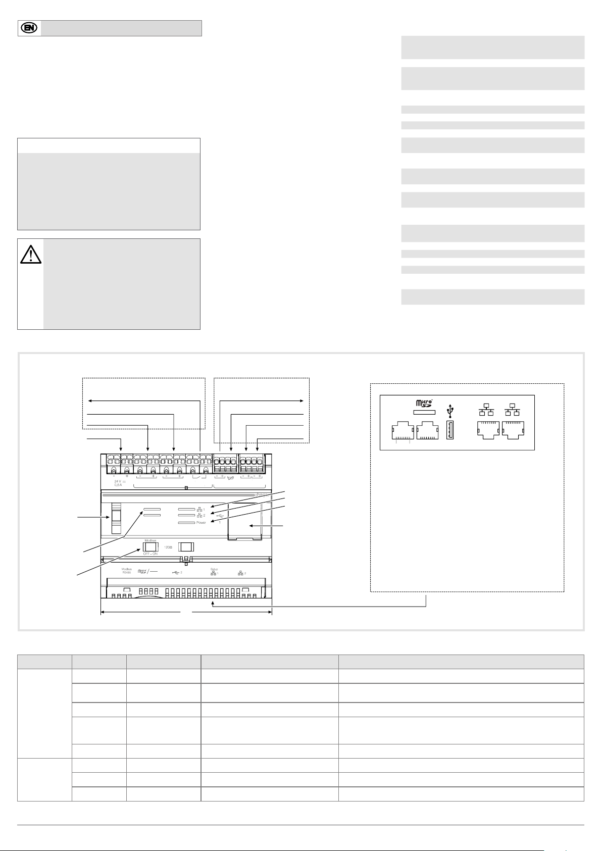
Front face and connections
Digital Analog
Output relay
Digital input
Digital input
24 V s SELV
HTG410H
Setup (1)
Selector
LED
Modbus
RS485
Termination
resistor
120 Ω
Modbus RS485 (2)
Setup
ON
OFF
Input 1
Modbus
Input 2
Output
0 - 10 V output
PT 100 input
4 - 20 mA input
4 - 20 mA input
Digital
DiDiggititaa
Input
Output
PT100
V 4-20 mA
0-10
Input 1 Input 2
LED
Analog
Ethernet 1
Ethernet 2
Power ON
ututppuu
1
Modbus RS485
18
2
34 56
1 Micro SD memory card slot
2 RJ45 port Modbus RS485
pin4: D1 or B/B' or "+" / green wire
pin5: D0 or A/A' or "-" / yellow wire
pin8: Common or C/C' or 0VL / brown wire
Setup
2
1
2
3 Not used
USB 2.0
4 USB 2.0
RJ45 Setup port - Ethernet 1
5
6 RJ45 port - Ethernet 2
Important: The RS485 Modbus circuits must be connected only
to external RS485 Modbus circuits that are Safety Extra-Low
Voltage (SELV).
6 0
6 0
LED information
LED Colour State Status Solution
Power
Modbus
RS485 /
Ethernet 1 /
Ethernet 2
Green Fixed Functional product. /
Green
or orange
Blinking Product initialisation.
Red Blinking Product enters in power reserve. Wait during the shutdown progress.
Red or orange Fixed Software startup problem.
Off Product not powered. Check the power supply.
Green Fixed / blinking Connected and functional network. /
Off No communication network detected. Check the connection.
Red Fixed / blinking Communication fault. Check the conguration of links.
Wait for initialisation.
If the indication remains, refer to manual.
Perform a reset by switching the power supply off.
Wait for LED to switch off before switching the power supply on.
If the indication remains, refer to manual.
6LE001602Bc2
Page 3

OO
tt
ll
A
Le HTG410H est un concentrateur et serveur de
données multi-énergies. La version HTG411H est
livrée en plus avec une carte micro SD de 4 Go.
Il est destiné à configurer système et produits,
relever, stocker et horodater les informations des
produits connectés. Il traite ces informations et
surveille la qualité de la distribution électrique. Il
les met à disposition de l’utilisateur au travers d’un
webserveur embarqué. Ce produit peut être rendu
accessible depuis le réseau Internet.
Pré-requis pour l’installation :
Matériel :
- Un ordinateur avec navigateur internet
(Chrome recommandé),
- Un câble Ethernet RJ45.
Dans le cas d’un réseau Ethernet étendu :
- une prise réseau Ethernet,
- le nom du produit sur le réseau,
- une adresse IP statique ou dynamique,
- le masque du réseau.
Appareil à installer uniquement par un
installateur électricien selon les normes
d’installation en vigueur dans le pays.
Ne pas installer ce module à l’extérieur
du bâtiment.
Alimentation via Ethernet (PoE) interdit.
En mode "Setup ON", le HTG410H active
son serveur DHCP sur le port "Setup Ethernet 1".
Face avant et connections
Installation
Le HTG410H / HTG411H se clipse directement sur un
rail DIN.
Mise en œuvre
1. Raccorder les entrées / sorties sur le bornier du
HTG410H / HTG411H.
2. Connecter les réseaux Modbus et Ethernet le cas
échéant.
3. Activer la résistance de terminaison 120 Ω
(sélecteur (2) à mettre sur "ON") si le produit est en
extrémité de réseau Modbus.
4. Vérier que le sélecteur "Setup" (1) soit en position
"OFF".
5. Connecter l’alimentation 24 V s (TBTS, SELV).
Première conguration
1. Lancer la mise à jour du logiciel :
a) télécharger la dernière version du logiciel à partir
de http://hgr.io/r/htg410h ou http://hgr.io/r/htg411h
b) décompresser le chier téléchargé
c) lire le chier «readme.txt»
2. Connecter l’ordinateur au port "Setup - Ehernet
1" du HTG410H / HTG411H à l’aide du câble
Ethernet.
3. Mettre le sélecteur "Setup" (1) en position "ON".
4. Couper l’alimentation, puis remettre le produit sous
tension.
5. Lancer le navigateur internet sur l’ordinateur.
6. Saisir : url : https://192.168.0.1
7. Paramétrage du HTG410H / HTG411H, se reporter
login : admin
password : admin
à la notice d’utilisation, téléchargeable sur le site
internet http://hgr.io/r/htg410h ou http://hgr.io/r/
htg411h ou en ashant le Datamatrix.
Caractéristiques techniques
Alimentation très basse
tension de sécurité externe
Consommation typique
Communication réseau
Ethernet
Communication réseau
Modbus
T° de fonctionnement
T° de stockage
Humidité stockage
Entrée digitale TOR 1 et 2
Entrée analogique
1 et 2
4 - 20 mA
Entrée PT 100
Sortie digitale TOR
Nombre de cycles du relais
Sortie analogique
Raccordement alimentation,
entrées digitales, sortie
digitale.
Raccordement entrées
analogiques, sortie
analogique
Indice de protection
Masse
Altitude maximale
d'utilisation
Carte micro SD
Port USB 1
(en façade)
Port USB 2
(sous le produit)
*: L'utilisation du produit à la température maximale peut réduire sa durée de vie.
0 - 10 V Impédance mini
Ethernet - TCP / IP -
RJ100 / 45 base - T /
RS485 Modbus RJ45
%95 max HR à °55C
Impédance d'entrée
Compatible EN 60751
5 à 30 V s / v 10 mA à 3 A
resistif contact sec
connecteur standard
connecteur standard
24 V s
(TBTS, SELV)
+/- 10 %
7 VA
IEEE 802.3
°25- à °70+C*
°55- à °85+C
15 à 27 V
<300 Ohms
Sonde 2 fils -
100000
>= 1 kOhms
2,5 - 0,75 mm²
1,5 - 0,2 mm²
IP 20
290 g
2000 m
Classe 10
USB 2.0 Type A
USB 2.0 Type A
s
Digitale Analogique
Sortie relais
Entrée TOR
Entrée TOR
24 V s TBTS, SELV
Sortie 0 - 10 V
Entrée PT 100
Entrée 4 - 20 mA
Entrée 4 - 20 mA
1
Modbus RS485
18
2
Digital
DigitDigitaa
Input
Output
PT100
V 4-20 mA
0-10
Input 1 Input 2
Led
Analog
Ethernet 1
Ethernet 2
Power
USB 2.0
Important : Le réseau RS485 Modbus ne doit être uniquement
raccordé à un réseau RS485 Modbus externe qui soit Très
Basse Tension de Sécurité (TBTS - SELV).
Sélecteur (1)
Setup
Led
Modbus
RS485
Résistance
de terminaison
120 Ω
Modbus RS485 (2)
HTG410H
Setup
ON
OFF
Input 1
Modbus
Input 2
Output
ututppuu
6 0
Fonctionnement des LED
Led Couleur Etat Signication Correction du défaut
Power
Modbus
RS485 /
Ethernet 1 /
Ethernet 2
Vert Fixe Produit fonctionnel. /
Vert
ou orange
Clignotant Initialisation du produit.
Rouge Clignotant
Rouge
ou orange
Fixe Problème de démarrage du logiciel.
Le produit entre dans la réserve de
marche.
Attendre la n de l’initialisation.
Si l’indication persiste, consulter la notice.
Attendez pendant la progression de l'arrêt.
Effectuer une réinitialisation en coupant l’alimentation.
Attendre l’extinction des Led avant de remettre le produit
sous tension. Si l’indication persiste, consulter la notice.
Eteinte Produit non alimenté. Vérier l’alimentation électrique.
Vert Fixe / clignotant Réseau raccordé et fonctionnel. /
Eteinte
Aucun réseau de communication
détecté.
Vérier le raccordement.
Rouge Fixe / clignotant Défaut de communication. Vérier la conguration des liaisons.
Setup
2
1
2
34 56
1 Logement pour carte mémoire Micro SD
2 Port RJ45 Modbus RS485
broche4 : D1 ou B/B' ou "+" / conducteur vert
broche5 : D0 ou A/A' ou "-" / conducteur jaune
broche8 : Commun ou C/C' ou 0VL / conducteur marron
3 Non utilisé
4 USB 2.0
5 Port RJ45 Setup - Ethernet 1
6 Port RJ45 - Ethernet 2
6LE001602Bc3
Page 4

OO
tt
A
E
Der HTG410H ist ein Energiemonitoringserver mit
dem Sie Ihr System und Ihre Produkte konfigurieren
können. Die HTG411H Version wird zusätzlich mit
einer 4GB Micro SD-Karte geliefert. Er sammelt,
speichert und verarbeitet die Messwerte der
angeschlossenen Produkte mit Zeitstempel.
Zusätzlich überwacht er die Qualität der
Elektroinstallation und macht Sie für die Benutzer
auf einem integrierten Webserver sichtbar. Diese
Daten können dann über das Internetnetzwerk
ausgelesen werden.
Voraussetzungen für die Installation :
Ausstattung :
- Ein Computer mit Internet-Browser
(Chrome empfohlen),
- Ein RJ45 Ethernet-Kabel.
Im Falle eines erweiterten Ethernet-Netzwerkes :
- Eine Ethernet-Netzwerkbuchse
- Produktname im Netzwerk
- eine statische oder dynamische IP-Adresse
- Die Netzwerkmaske
Einbau und Montage dürfen nur durch eine
Elektrofachkraft gemäß den einschlägigen
Installationsnormen des Landes erfolgen.
Das Gerät ist für die Verwendung im Freien
nicht geeignet.
Stromversorgung via Ethernet (PoE)
verboten.
Im aktivierten "Setup ON" Modus stellt der
HTG410H einen DHCP Server am "Setup
Ethernet 1" Port zur Verfügung.
Front Seite und Anschlüsse
Einbau
Der HTG410H / HTG411H kann direkt auf eine
Hutschiene montiert werden.
Implementierung
1. Ein- und Ausgänge an der Klemmleiste HTG410H /
HTG411H anschließen.
2. Modbus und Ethernet Verbindung anschließen.
3. Abschlusswiderstand 120 Ω des Modbus aktivieren
(Schalter (2) auf „ON“ setzen) falls das Produkt als
erstes oder letztes Produkt im Netzwerk genutzt
wird.
4. Prüfen ob Schalter „Setup“ (1) auf „OFF“ Position
steht.
5. 24 V s (SELV) Stromversorgung anschließen.
Erste Konguration
1. Starten Sie das Software-Update:
a) Laden Sie die neueste Software-Version von
http://hgr.io/r/htg410h oder http://hgr.io/r/htg411h
b) Entpacken Sie die heruntergeladene Datei
c) lesen Sie die Datei „readme.txt“
2. Computer mit einem Ethernet Kabel an der „Setup
- Ehernet 1“ Buchse anschließen.
3. Schalter „Setup“ (1) auf die „ON“ Position stellen.
4. Aus- und wieder einschalten der 24 V
Stromversorgung um einen Reset des Gerätes zu
erzeugen.
5. Webbrowser am PC starten.
6. Eingabe von : url : https://192.168.0.1
7. HTG410H / HTG411H laut Bedienungsanleitung
einstellen (Bedienungsanleitung online unter http://
hgr.io/r/htg410h oder http://hgr.io/r/htg411h oder
durch scannen der Datenmatrix erhältlich).
login : admin
password : admin
Technische Daten
Externe
Sicherheitskleinspannung
Spannungsversorgung
Typische Energiebedarf
Ethernet
Netzwerkkommunikation
Modbus
Netzwerkkommunikation
Betriebstemperatur
Lagertemperatur
Luftfeuchtigkeit Lagerung
Binäre Digitaleingänge (1
und 2)
Analogeingang
PT 100 - Eingang
4 - 20 mA
(1 und 2)
Binärer Digitalausgang
Anzahl Relaiszyklen
Analogausgang
Anschlussquerschnitt
Versorgung, digitale Einund Ausgänge
Anschlussquerschnitt
analoge Ein- und Ausgänge
IP - Schutzklasse
Gewicht
Maximale Betriebshöhe
Micro SD - Karte
USB - Anschluss
(front)
USB port 2
(unter dem Produkt)
*: Die Verwendung dieses Produkts bei Maximaltemperatur kann
die Lebensdauer verringern.
0 - 10 V Minimale Impedanz
Ethernet - TCP / IP -
RJ45 / 100 base - T /
RS485 Modbus RJ45
-25° bis +70°C*
-55° bis +85°C
max 95% RF bei 55°C
Eingangsimpedanz
2-Drahtfühler -
laut EN 60751
5 bis 30 V s / v 10 mA
potentialfreier Kontakt
0,75 - 2,5 mm²
USB 2.0 Type A
Stecker - Standard
USB 2.0 Type A
Stecker - Standard
24 V s
(SELV)
+/- 10 %
7 VA
IEEE 802.3
15 bis 27 V
<300 Ohms
bis 3 A
100000
>= 1 kOhms
0,2 - 1,5 mm²
IP 20
290 g
2 000 m
Klass 10
s
Digitale Analog
Input
Input 1 Input 2
PT100
V 4-20 mA
Ausgang 0 - 10 V
PT 100 - Eingang
Eingang 4 - 20 mA
Eingang 4 - 20 mA
LED
Analog
Ethernet 1
Ethernet 2
Power
USB 2.0
Wichtig: Die RS485 Modbus Schaltungen dürfen nur mit externen
RS485 Modbus verbunden Schaltungen, mit Sicherheitskleinspannung
(SELV) verbunden werden.
Schalter (1)
Setup
LED
Modbus
RS485
bschlusswiderstand
120 Ω
Modbus RS485 (2)
Relaisausgang
Digitaleingang
Digitaleingang
24 V s SELV
HTG410H
Setup
ON
OFF
Input 1
Modbus
Output
ututppuu
Input 2
Output
0-10
Digital
DiDiggitalital
6 0
LED - Betrieb
LED Farbe Status Bedeutung Fehlerbehebung
Power
Modbus
RS485 /
Ethernet 1 /
Ethernet 2
Grün Leuchtet Das Produkt ist funktionsfähig. /
Grün
oder Orange
Blinkt Initialisierungs-Phase.
Auf Initialisierung warten.
Wenn die Anzeige nicht erlischt, Bedienungsanleitung beachten.
Rot Blinkt Produkt tritt in die Gangreserve ein. Warten Sie während des Herunterfahrens.
Rot
oder Orange
Leuchtet Software Startproblem.
24 V Spannungsversorgung ausschalten und warten bis die LEDs
erlöschen. Danach Spannungsversorgung wieder einschalten.
Wenn die Anzeige nicht erlischt, Bedienungsanleitung beachten.
Ausgeschaltet Keine Stromversorgung. Überprüfen Sie die Stromversorgung.
Grün Leuchtet / Blinkt
Netzwerk angeschlossen
und funktionsfähig.
/
Ausgeschaltet Kein Netzwerk vorhanden. Überprüfen Sie die Verbindung mit dem Netzwerk.
Rot Leuchtet / Blinkt Kommunikationsfehler. Überprüfen Sie die Konguration der Verbindungen.
Setup
1
Modbus RS485
18
2
2
1
34 56
1 Speicherkartensteckplatz Micro SD
2 RJ45-Schnittstelle RS485 Modbus RTU
Pin4: D1 oder B / B 'oder "+" / grünen Draht
Pin5: D0 oder A / A 'oder "-" / gelben Draht
Pin8: Common oder C / C 'oder 0VL / braun Draht
3 3 Nicht verwendet
4 USB 2.0
5 RJ45 Setup port - Ethernet 1
6 RJ45 port - Ethernet 2
2
6LE001602Bc4
Page 5

OO
tt
ll
M
HTG410H to rejestrator danych i serwer monitoringu
energii. Wersja HTG411H jest wyposażona
dodatkowo w kartę pamięci microSD 4 GB. Serwer
przeznaczony jest do konfiguracji produktów i
systemów oraz do zbierania, oznaczania stemplem
czasowym i przechowywania danych pomiarowych,
odczytywanych z powiązanych urządzeń. Przetwarza
on informacje i monitoruje parametry ilościowe i
jakościowe energii elektrycznej oraz udostępnia
je użytkownikom za pomocą połączenia do
wbudowanego webserwera. Dostęp do urządzenia jest
możliwy przez sieć lokalną Ethernet lub internetową.
Voraussetzungen für die Installation :
- Połączenie bezpośrednie:
- komputer PC z wbudowaną przeglądarkę
internetową (zalecana Google Chrome)
- kabel Ethernet RJ-45
- Sieć lokalna (LAN):
- gniazdo sieciowe Ethernet RJ-45
- unikalna nazwa produktu w sieci
- statyczny lub dynamiczny adres IP
- maska podsieci
Einbau und Montage dürfen nur durch eine
Elektrofachkraft gemäß den einschlägigen
Installationsnormen des Landes erfolgen.
Das Gerät ist für die Verwendung im Freien
nicht geeignet.
Stromversorgung via Ethernet (PoE)
verboten.
Im aktivierten "Setup ON" Modus stellt der
HTG410H einen DHCP Server am "Setup
Ethernet 1" Port zur Verfügung.
Widok i połączenia - przód obudowy
Instalacja
Serwer HTG410H / HTG411H musi być zainstalowany
na szynie TH35 (DIN).
Podłączenie
1. Podłączyć przewody do zacisków wejściowych i
wyjściowych.
2. Podłączyć przewody sieci Modbus / Ethernet.
3. Jeżeli HTG410H / HTG411H jest urządzeniem
końcowym w sieci Modbus, włączyć rezystor
120 Ω (przełącznik (2) przesunąć w prawo, do
pozycji ON").
4. Sprawdzić, czy przełącznik "Setup" znajduje się w
pozycji "ON".
5. Podłączyć napięcie zasilające 24 V s (zewnętrzny
zasilacz SELV).
Pierwsza konguracja
1. Uruchomić aktualizację oprogramowania:
a) pobrać najnowszą wersję oprogramowania ze
strony http://hgr.io/r/htg410h lubhttp://hgr.io/r/
htg411h
b) rozpakować pobrany plik
c) odczytać treść pliku «readme.txt»
2. Podłączyć komputer do gniazda RJ-45 "Setup 1"
za pomocą kabla Ethernet.
3. Zmienić pozycję przełącznika "Setup (1) do pozycji
"ON".
4. Wykonać reset napięcia zasilającego (wyłączenie i
ponowne jego załączenie).
5. Uruchomić przeglądarkę internetową w
komputerze.
6. Wprowadzić adres: https://192.168.0.1
7. Instrukcję pełnej konguracji HTG410H / HTG411H
można znaleźć w instrukcji obsługi, do pobrania ze
strony http://hgr.io/r/htg410h lub http://hgr.io/r/
htg411h oraz po zeskanowaniu kodu DataMatrix.
Login: admin
Hasło: admin
Charakterystyka techniczna
Bezpieczeństwo użytkonika
zapewnione przez napięcie
SELV
Nominalny pobór mocy
Komunikacja Ethernet
Komunikacja Modbus
Temperatura pracy
Temperatura
przechowywania
Wilgotność przy
przechowywaniu
Binarne wejścia cyfrowe 1 i 2
Wejście analogowe
4 - 20 mA
Wejście Pt100
1 i 2
Binarne wyjście cyfrowe
Liczba cykli przekaźnika
Wyjście analogowe
Przekrój przewodów zasilanie, wejścia cyfrowe,
wyjście cyfrowe
Przekrój przewodów wejścia analogowe, wyjście
analogowe
Stopień ochrony
Waga
Maksymalna wysokość pracy
Karta pamięci microSD
Port USB 1 (dostępny z
przodu obudowy)
Port USB 2 (dostępny od
spodu obudowy)
*: Stosowanie produktu w maksymalnej temperaturze może zmniejszyć jego
żywotność.
0 - 10 V Impedancja min
Ethernet - TCP/IP -
RJ45 / 100 base-T /
RS485 Modbus RJ-45
-25 ° do + 70 ° C *
-55 ° C do + 85 ° C
temperaturze 55 ° C
Impedancja wejściowa
Sonda 2-przewodowa -
zgodność z EN 60751
5 do 30 V s / v 10 mA do 3 A
rezystancyjne styki
złącze standardowe
złącze standardowe
24 V s
(SELV)
+/- 10 %
IEEE 802.3
max 95% HR w
15 do 27 V
< 300 Ohm
beznapięciowe
100000
>= 1 kOhm
0,75 - 2,5 mm²
0,2 - 1,5 mm²
2 000 m
Klasa 10
USB 2.0 typu A,
USB 2.0 typu A,
7 VA
IP 20
290 g
s
Złącza cyfrowe Złącza analogowe
Wyjście 10 - 0 V
Wejście 4 - 20 mA
Wejście 4 - 20 mA
Input
Input 1 Input 2
PT100
Wejście Pt100
LED
Analog
Ethernet 1
Ethernet 2
Zasilanie “Power ON”
USB 2.0
Uwaga: Obwody RS485 Modbus muszą być podłączone tylko do
zewnętrznych układów RS485 Modbus, które zasilane są
napięciem SELV.
Zasilanie “24 V s SELV”
Przełącznik
Setup (1)
LED
Modbus
RS485
Rezystor
końcowy
120 Ω
Modbus RS485 (2)
Przekaźnik wyjściowy
Wejście cyfrowe
Wejście cyfrowe
Input 1
HTG410H
Setup
ON
OFF
Modbus
Input 2
Output
ututppuu
Output
V 4-20 mA
0-10
Digital
DiDiggititaa
6 0
6 0
Informacje przekazywane przez diody LED
LED Kolor Stan diody LED Status Rozwiązanie
Moc
Modbus
RS485 /
Ethernet 1 /
Ethernet 2
Zielony Światło stałe Produkt działa prawidłowo. /
Zielone lub
Pomarańczowy
Pulsuje Inicjalizacja produktu.
Poczekaj na inicjalizację.
Jeżeli wskazanie pozostaje, patrz instrukcja.
Czerwony Pulsuje Produkt wchodzi do rezerwy mocy. Zaczekaj podczas postępu zamykania.
Czerwony lub
Pomaranczowy
Światło stałe
Problem z uruchamianiem
oprogramowania.
Wykonać reset przez wyłączenie i włączenie napięcia zasilającego.
Poczekaj na wygaszenie diody LED przed włączeniem zasilania.
Jeżeli wskazanie pozostaje, patrz instrukcja.
Brak Brak zasilania produktu. Sprawdź zasilanie.
Zielony
Światło stałe /
Pulsuje
Połączenie sieciowe prawidłowe. /
Brak Nie wykryto sieci komunikacyjnej. Sprawdź połączenie.
Czerwony
Światło stałe /
Pulsuje
Błąd komunikacji. Sprawdź kongurację łącza.
Setup
1
Modbus RS485
18
2
2
1
34 56
1 Gniazdo karty pamięci microSD
2 RJ45 Port RS485 Modbus
pin4: D1 lub B/B' lub "+" - przewód zielony
pin5: D0 lub A/A' lub "-" / - przewód żółty
pin8: Common lub C/C' or 0VL / - przewód brązowy
3 Nieużywany
4 USB 2.0
5 Port RJ45 - Ethernet 1 (Setup)
6 Port RJ45 - Ethernet 2
2
6LE001602Bc5
Page 6

OO
tt
ll
T
O HTG410H é um concentrador de dados e
servidor multi-energia. A versão HTG411H inclui
adicionalmente um cartão de 4 GB micro SD.
Destina-se a configurar sistemas e produtos,
a receber, armazenar e registar com hora/data
as informações dos produtos ligados. Processa
estas informações e monitoriza a qualidade da
distribuição de energia eléctrica, disponibilizando-
as ao utilizador, por meio de webserver integrado.
.Este produto é acessível a partir da Internet
Pré-requisitos para a instalação:
Equipamentos:
- Um computador com navegador de internet
(Chrome recomendado),
- Um cabo RJ45 Ethernet.
No caso de ligação via uma rede Ethernet
existente:
- Uma tomada de rede Ethernet,
- Nome do produto na rede,
- Um endereço IP estático ou dinâmico,
- A máscara de rede.
Este dispositivo deve ser instalado apenas
por um electricista prossional, de acordo
com as normas de instalação em vigor.
Não instalar o módulo no exterior do
edifício.
Alimentação através de Ethernet (PoE) é
proibida.
Em modo "Setup ON", o HTG410H /
HTG411H activa seu servidor DHCP na
porta "Setup - Ethernet 1".
Parte frontal e ligações
Instalação
O HTG410H / HTG411H deve ser montado em calha
DIN.
Colocação em serviço
1. Ligue as entradas / saídas no bloco de terminais
do HTG410H / HTG411H.
2. Ligue as redes Modbus e Ethernet, de acordo com
as regras.
3. Active a resistência de 120 Ω de terminação de
linha (selector (2) na posição "ON"), se o produto
estiver instalado numa das extremidades da rede
Modbus.
4. Verique se o selector "Setup" (1) está na posição
"OFF".
5. Ligue a fonte de alimentação de 24 V s (SELV).
Primeira conguração
1. Iniciar a actualização do software:
a) fazer download da última versão do software
através de http://hgr.io/r/htg410h ou http://hgr.io/r/
htg411h
b) descompactar o cheiro obtido
c) ler o cheiro «readme.txt»
2. Ligar o computador à cha RJ45 "Setup - Ehernet
1" do HTG410H / HTG411H, utilizando um cabo
Ethernet.
3. Coloque o selector «Setup» (1) na posição «ON».
4. Forçar uma reinicialização, desligando a sua
alimentação e ligando-a novamente.
5. Abra o navegador da internet no computador.
6. Introduzir o url : https://192.168.0.1
7. Para congurar o HTG410H / HTG411H, consulte o
manual de instalação, disponível para download via
http://hgr.io/r/htg410h ou http://hgr.io/r/htg411h
ou faça scan do Datamatrix.
login : admin
password : admin
Características técnicas
Fonte de alimentação
de Tensão Reduzida de
Segurança (TRS)
Consumo típico
Comunicação rede
Ethernet
Comunicação rede
Modbus
Temperatura de
funcionamento
Temperatura de
armazenamento
Humidade de
armazenamento
Entrada digital binária 1 e 2
Entrada analógica
4 - 20 mA
Entrada PT 100
1 e 2
Saída digital binária
Número de ciclos do relé
Saída analógica
Ligações fonte de
alimentação, entradas
digitais, saída digital
Ligações entradas
analógicas, saída analógica
Índice de protecção
Peso
Altitude máxima de
funcionamento
Cartão micro SD
Porta USB 1
(parte frontal)
Porta USB 2
(sob o produto)
*: A utilização do produto à temperatura máxima pode reduzir o seu tempo de
vida útil.
0 - 10 V Impedância min.
Ethernet - TCP / IP -
RJ45 / 100 base - T /
RS485 Modbus RJ45
-25 ° a + 70 ° C *
-55 ° C a + 85 ° C
95% FC máx a 55 ° C
Impedância de entrada
Sonda de 2 fios -
conforme EN 60751
5 a 30 V s / v 10 mA a 3 A
resistivo contacto seco
conector standard
conector standard
24 V s
(SELV)
+/- 10 %
7 VA
IEEE 802.3
15 a 27 V
<300 Ohms
100000
>= 1 kOhms
0,75 - 2,5 mm²
0,2 - 1,5 mm²
IP 20
290 g
2 000 m
classe 10
USB 2.0 Tipo A
USB 2.0 Tipo A
s
Digital Analógico
Saída relé
Entrada digital
Entrada digital
24 V s SELV
Saída 10 - 0 V
Saída PT 100
Saída 4 - 20 mA
Saída 4 - 20 mA
Modbus RS485
2
Digital
DiDiggititaa
Input
Output
PT100
0-10
V 4-20 mA
Input 1 Input 2
LED
Analog
Ethernet 1
Ethernet 2
Power ON
USB 2.0
Importante: Os circuitos RS485 Modbus devem ser ligados apenas
a circuitos externos RS485 Modbus que sejam do tipo SELV
(Safety Extra-Low Voltage).
Selector (1)
Setup
LED
Modbus
RS485
Resitência
terminal
120 Ω
Modbus RS485 (2)
HTG410H
Setup
ON
OFF
Input 1
Modbus
Input 2
Output
ututppuu
6 0
6 0
Funcionamento dos LED
LED Cor Estado Signicado Correcção do defeito
Alimentação
Modbus
RS485 /
Ethernet 1 /
Ethernet 2
Verde Fixo Produto funcional. /
Verde
ou laranja
A piscar Inicialização do produto.
Esperar pela inicialização.
Se a indicação persistir, consulte o manual.
Vermelho A piscar O produto entra na reserva de energia. Aguarde durante o progresso do desligamento.
Vermelho
ou laranja
Fixo Problema de inicialização do software.
Execute uma reinicialização desligando a alimentação.
Espere pelo desligar do LED antes de voltar a colocar o produto sob
tensão.
Se a indicação persistir, consulte o manual.
Desligado Produto não alimentado Vericar a fonte de alimentação.
Verde Fixo / a piscar Rede ligada e a funcionar /
Desligado
Nenhuma rede de comunicação
detectada.
Verique as ligações
Vermelho Fixo / a piscar Falha de comunicação. Verique a conguração dos links.
Setup
1
18
2
1
2
34 56
1 Slot para cartão de memória Micro SD
2 Ficha RJ45 Modbus RS485
pin4: D1 ou B/B' ou "+" / condutor verde
ppin5: D0 ou A/A' ou "-" / condutor amarelo
pin8: Comum ou C/C' ou 0VL / condutor castanho
3 Não usado
4 USB 2.0
5 Ficha RJ45 Setup - Ethernet 1
6 Ficha RJ45 - Ethernet 2
6LE001602Bc6
Page 7

OO
tt
ll
R
El HTG4110H es un concentrador y servidor
de datos multimedida. La versión HTG411H se
entrega, además, con una tarjeta de 4 GB micro SD.
Destinado a configurar el sistema y los productos
conectados. Se procesa esta información y
monitoriza la calidad de la distribución eléctrica
y la hace disponible para el usuario a través de
un servidor web embebido. Este producto es
accesible desde Internet.
Requisitos para la instalación:
Equipo:
- Un ordenador con navegador de Internet (Chrome
recomendado),
- Un cable Ethernet RJ45.
En el caso de una red Ethernet extendida :
- Una toma de red Ethernet,
- Nombre del producto en la red,
- Una dirección IP estática o dinámica,
- la máscara de red.
Este dispositivo debe ser instalado por
un electricista profesional instalador de
acuerdo con las normas locales aplicables
para la instalación.
No instale este módulo fuera del edicio.
Fuente de alimentación a través de
Ethernet (PoE) prohibido.
En modo "Setup ON", el HTG410H /
HTG411H activa su servidor DHCP en
"Conguración - en el puerto Ethernet 1".
Cara frontal y conexiones
Instalación
El HTG410H / HTG411H debe montarse en un carril
DIN.
Implementación
1. Conectar las entradas / salidas del bloque de
terminales HTG410H / HTG411H.
2. Conectar el Modbus y redes Ethernet según sea
apropiado.
3. Habilitar la resistencia de 120 Ω con el selector (2)
en posición "ON" si el producto está instalado al
nal de la línea Modbus.
4. Comprobar que el selector de "conguración" (1)
está en la posición "OFF".
5. Conectar la fuente de alimentación de 24 V s (SELV).
Primera conguración
1. Iniciar la actualización de software:
a) descargar la última versión del software de
http://hgr.io/r/htg410h o http://hgr.io/r/htg411h
b) descomprimir el archivo descargado
c) leer el archivo "readme.txt"
2. Conectar el ordenador al RJ45 "Conguración
- Ehernet 1" conector de HTG410H / HTG411H
mediante el cable Ethernet.
3. Colocar el interruptor de "conguración" (1) en la
posición "ON".
4. Realice un reset, apagando la fuente de
alimentación y encendiéndola de nuevo.
5. Active el navegador web en el ordenador.
6. Introducir: url : https://192.168.0.1
7. Conguración de la HTG410H / HTG411H, consulte
la guía del usuario, descargable desde http://hgr.
io/r/htg410h o http://hgr.io/r/htg411h sitio web o
con el escaneo Datamatrix.
iniciar sesión: admin
contraseña : admin
Características técnicas
seguridad externa muy
baja tensión de fuente de
alimentación
El consumo típico
la comunicación de red
Ethernet
Comunicación de red
Modbus
Temperatura de
funcionamiento
Temperatura de
almacenamiento
Humedad de
almacenamiento
Entrada digital binaria 1 y 2
Entrada analógica
4 - 20 mA
Entrada PT100
1 y 2
Salida digital binaria
Número de ciclos de relé
Salida analógica
Fuente de alimentación,
entradas digitales, conexión
de salida digital
Las entradas analógicas,
conexión de salida
analógica
Grado de protección
Peso
Altura máxima de operación
Tarjeta micro SD
1 puerto USB
(cara frontal)
Puerto USB 2
(en el producto)
*: El uso de producto a la temperatura máxima puede reducir su esperanza de
vida.
0 - 10V Impedancia min
Ethernet - TCP / IP - RJ45 /
100 Base - T / IEEE 802.3
RS485 Modbus RJ45
-25 ° a + 70 ° C *
95% de la FC máx a 55 ° C
Impedancia de entrada
5 a 30 V s / v 10 mA a 3 A
contacto seco resistiva
conector estándar
conector estándar
24 V s
(SELV)
+/- 10 %
7 VA
-55 ° a + 85 ° C
15 a 27 V
<300 Ohms
Sonda 2 hilos -
EN60751
100000
> = 1kOhm
0,75 - 2,5 mm²
0,2 - 1,5 mm²
IP 20
290 g
2 000 m
Clase 10
USB 2.0 tipo A
USB 2.0 tipo A
s
Digital Analógico
0 - 10 V Salida
PT 100 Entrada
4 - 20 mA Entrada
4 - 20 mA Entrada
Input 1 Input 2
Analog
Led
Ethernet 1
Ethernet 2
Power
USB 2.0
Setup (1)
Selector
Salida relé
Entrada digital
Entrada digital
24 V s TBTS, SELV
HTG410H
Setup
ON
OFF
Input 1
Modbus
Input 2
Output
Digital
DigitDigitaa
Input
Output
PT100
V 4-20 mA
0-10
ututppuu
LED
Modbus
RS485
Resistencia
fin de línea
120 Ω
Modbus RS485 (2)
6 0
Información LED
LED Color Estado Estado Solución
Power Verde Fijo Producto funcional /
Modbus
RS485 /
Ethernet 1 /
Ethernet 2
Verde o
naranja
Rojo Parpadeo El producto ingresa en la reserva de
Rojo o
naranja
Apagado El producto no alimentado. Compruebe la fuente de alimentación.
Verde Fija / intermitente Conectado a la red y funcional. /
Rojo Fija / intermitente Fallo de comunicación. Compruebe la conguración de enlaces.
Parpadeo inicialización del producto. Espere Espere a que.
Si la indicación permanece, consulte el manual.
Espere durante el progreso de apagado.
energía.
Fijo Problema de inicio de software. Realice un reset desconectado la fuente de alimentación.
Espere a que el LED se apague antes de volver a conectar la fuente
de alimentación.
Si la indicación permanece, consulte el manual.
Apagado No se detectó red de comunicación. Compruebe la conexión.
Setup
1
Modbus RS485
18
2
2
1
2
34 56
1 Ranura para tarjeta de memoria Micro SD
2 Puerto RJ45 Modbus RS485
Pin4: D1 o B/B o “+” / cable verde
Pin5: D0 o A/A o “-” / cable amarillo
Pin8: Común o C/C o 0VL / cable marrón
3 Sin uso
4 USB 2.0
5 Puerto RJ45 Configuración – Ethernet 1
6 Puerto RJ45 – Ethernet 2
Importante: Los circuitos Modbus RS485 deben conectarse únicamente
a circuitos externos Modbus RS485 alimentados mediante
“Safety Extra-Low Voltage” (SELV ).
6LE001602Bc7
Page 8

A
OO
tt
I
De HTG410H is een multi-energy data logger
en server. De HTG411H versie wordt bovendien
geleverd met een 4 GB micro SD-kaart. Het verzamelt
gegevens en slaat deze op met een tijdregistratie
en het configureert de aangesloten producten. Het
bewaakt de kwaliteit van een elektrische installatie
en stelt de verwerkte gegevens beschikbaar via een
ingebouwde webserver en webpagina Dit product
communiceert via een datanetwerk
Benodigdheden voor de installatie:
Benodigd:
- Een computer met internet browser (Chrome
aanbevolen),
- Een RJ45 Ethernet-kabel.
B een uitgebreid Ethernet-datanetwerk:
- Een Ethernet-netwerk-aansluiting,
- Unieke netwerknaam
- Een statisch of dynamisch IP-adres,
- het netwerk masker.
Este dispositivo debe ser instalado por
un electricista profesional instalador de
acuerdo con las normas locales aplicables
para la instalación.
No instale este módulo fuera del edicio.
Fuente de alimentación a través de
Ethernet (PoE) prohibido.
En modo "Setup ON", el HTG410H /
HTG411H activa su servidor DHCP en
"Conguración - en el puerto Ethernet 1".
Voorzde en aansluitingen
Installatie
De HTG410H / HTG411H moet worden gemonteerd
op een DIN-rail.
Implementatie
1. Sluit de ingangen / uitgangen van de HTG410H /
HTG411H aan op de schroefklemmen.
2. Sluit de Modbus en Ethernet-netwerken aan waar
nodig.
3. Schakel de 120 Ω afsluitweerstand
(keuzeschakelaar (2) op «ON») als het product aan
het eind van het Modbus-netwerk wordt geplaatst.
4. Controleer of de schakelaar «Setup» (1) in stand
«OFF».
5. Sluit de 24 V s voeding aan (SELV).
Eerste conguratie
1. Start de software-update:
a) download de nieuwste softwareversie van http://
hgr.io/r/htg410h of http://hgr.io/r/htg411h
b) Unzip het gedownloade bestand
c) Lees het bestand «readme.txt»
2. Sluit de computer aan op de RJ45 "Setup - Ehernet
1" connector van HTG410H / HTG411H met behulp
van de Ethernet-kabel.
3. Zet schakelaar "Setup" (1) in stand "ON" (Aan).
4. Voer een server reset uit, door de voeding uit en
weer aan te schakelen.
5. Start de webbrowser op de computer.
6. Typ de volgende URL: https://192.168.0.1
7. Werkwze om de HTG410H / HTG411H in te
stellen, vindt u in de handleiding, te downloaden
vanaf http://hgr.io/r/htg410h of http://hgr.io/r/
htg411h website of scan de QR-code.
Gebruikersnaam: admin
Wachtwoord: admin
Technische eigenschappen
Extra lage zeer veilige
spanning
Energieverbruik
Ethernet-netwerk
communicatie
Modbus-netwerk
communicatie
bedrfstemperatuur
Temperatuur b opslag
Luchtvochtigheid b opslag
Binaire digitale ingang 1 en 2
Analoge ingang
4 - 20 mA
PT 100-ingang
1 en 2
Binaire digitale uitgang
Aantal relais cycli
Analoge uitgang
Voeding, digitale ingangen,
digitale uitgang verbinding
Aansluitdoorsnede
bedrading op analoge in- en
uitgangen
Beschermingsgraad
Gewicht
Maximale bedrfshoogte
Micro SD-kaart
USB-poort 1
(voorkant)
USB-poort 2
(onder het product)
*: Het gebruik van het product b de maximale temperatuur reduceert de
levensverwachting.
0 - 10 V Belastingsimpedantie min
Ethernet - TCP / IP -
RJ45 / 100 base - T /
RS485 Modbus RJ45
-25 ° tot + 70 ° C *
95% HF max bij 55 ° C
Ingangsimpedantie
5 tot 30 V s / v 10 mA tot
resistief droog contact
standaard connector
standaard connector
+/- 10 %
IEEE 802.3
-55 ° tot + 85 ° C
15 tot 27 V
<300 Ohm
2-draads probe -
volgens EN 60751
1 kOhm of hoger.
0,75 - 2,5 mm²
0,2 - 1,5 mm²
class 10
USB 2.0 type A
USB 2.0 type A
24 V s
(SELV)
7 VA
3 A
100000
IP 20
290 g
2000 m
s
Digital Analog
Input
Input 1 Input 2
PT100
0 - 10 V uitgang
PT 100 ingang
4 - 20 mA ingang
4 - 20 mA ingang
Analog
LED
Ethernet 1
Ethernet 2
Power ON
USB 2.0
Digital ingang
24 V s SELV
Setup (1)
Selector
LED
Modbus
RS485
fsluitweerstand
120 Ω
Modbus RS485 (2)
uitgangsrelais
Digital ingang
HTG410H
Setup
ON
OFF
Input 1
Modbus
Input 2
Output
ututppuu
Output
V 4-20 mA
0-10
Digital
DiDiggitalital
6 0
6 0
Betekenis LED signalering
LED Kleur Gedrag Betekenis Noodzakelke actie
Voeding
Modbus
RS485 /
Ethernet 1 /
Ethernet 2
Groen Continu aan In bedrf /
Groen
of Oranje
Knipperen Product initialisatie.
Wacht op einde van de initialisatie.
B blvend signaal zie de instructies in de handleiding.
Rood Knipperen Product komt in gangreserve. Wacht tdens het afsluiten van de afsluiting.
Rood
of Oranje
Continu aan Software probleem.
Herstart product door de voedingspanning uit, aan te schakelen.
Wacht met inschakelen tot de LEDs uit zn.
B blvend signaal zie de instructies in de handleiding.
Uit Product is niet ingeschakeld. Controleer de voeding.
Groen
Rood
Continu aan /
knipperen
Uit
Continu aan /
knipperen
Aangesloten en functioneel netwerk. /
Geen communicatie netwerk
gedetecteerd.
Controleer de netwerkverbinding.
Communicatiefout. Controleer de verbindingsinstellingen.
Setup
1
Modbus RS485
18
2
2
1
2
34 56
1 Micro SD memory card slot
2 RJ45 port Modbus RS485
pin4: D1 or B/B' or "+" / green wire
pin5: D0 or A/A' or "-" / yellow wire
pin8: Common or C/C' or 0VL / brown wire
3 Not used
4 USB 2.0
5 RJ45 Setup port - Ethernet 1
6 RJ45 port - Ethernet 2
Belangrijk: Datanetwerken en RS485 netwerken SELV circuits.
Zorg voor de juiste isolatie voorwaarden.
6LE001602Bc8
Page 9

Ä
OO
tt
S
HTG410H är en multi-energi datalogger och server.
HTG411H versionen levereras dessutom med ett
4GB micro SD-kort. Avsikten är att konfigurera
system och produkter, samla in, lagra och
tidsstämpel för anslutna produkter. Den behandlar
denna information och övervakar kvaliteten på
eldistribution och gör den tillgänglig för användaren
genom en anluten webbserver. Denna produkt är
tillgänglig från Internet.
Nödvändig utrustning:
Utrustning:
- En dator med webbläsare (Chrome
rekommenderas),
- en RJ45 Ethernet-kabel.
I händelse av ett utökat Ethernet-nätverk:
- Ett Ethernet nätverksuttag,
- Produktnamn på nätverket,
- En statisk eller dynamisk IP-adress,
- Nätverksmask
Denna produkr får endast installeras
av en behörig elektriker enligt gällande
installationsregler.
Installera inte denna modul utanför
byggnaden.
Strömförsörjning via Ethernet (PoE)
förbjudet.
I "Setup ON" läge, aktiverar HTG410H /
HTG411H dess DHCP-servern på "Setup Ethernet 1" port.
Framsida och anslutningar
Installation
Den HTG410H / HTG411H skall monteras på DINskena.
Genomförande
1. Anslut in- / utgångar på HTG410H / HTG411H
plintar
2. Anslut Modbus och Ethernet-nätverk som är
lämpligt.
3. Aktivera 120 Ω avslutningsmotstånd (väljaren (2) för
att ställa in «ON») om produkten är monterad vid
slutet av Modbus nätverket.
4. Kontrollera att väljaren «Setup» (1) är i läge «OFF».
5. Anslut 24 V s strömförsörjning (SELV).
Första konguration
1. Starta programuppdateringen:
a) ladda ner den senaste programvaruversionen
från http://hgr.io/r/htg410h eller http://hgr.io/r/
htg411h
b) packa upp den nedladdade len
c) läsa len «readme.txt»
2. Anslut datorn till RJ45 "Setup - Ehernet en" kontakt
av HTG410H / HTG411H använder Ethernet-kabel.
3. Ställ omkopplaren «Setup» (1) i läge «ON».
4. Återställning är möjlig genom att föra omkopplaren
i läge "Off" på strömförsörjningen och sen föra den
i läge "On"
5. Aktivera webbläsare på datorn.
6. Skriv: url : https://192.168.0.1
logga in : admin
Lösenord : admin
7. Inställning av HTG410H / HTG411H nns i
instruktionsboken, nedladdningsbar ifrån http://
hgr.io/r/htg410h eller http://hgr.io/r/htg411h
webbplats eller med Datamatrix scanning.
Tekniska egenskaper
Extern
skyddsklenspännings
nätaggregat
Egen förbrukning
Ethernet
nätverkskommunikation
Modbus
nätverkskommunikation
Driftstemperatur
Förvaringstemperatur
fuktighet lagring
Binär digital ingång 1 och 2
Analog ingång
4 - 20 mA
PT 100 ingång
1 och 2
Binär digital utgång
Antal omkopplingar
Analog utgång
Strömförsörjning,
digitala ingångar, digitala
utgångsanslutningen
Analoga ingångar, analoga
utgångsanslutning
Kapslingklass
Vikt
Maximal arbetshöjd
Micro SD-kort
USB-port 1
(framsida)
USB-port 2
(under produkt)
*: Användning av produkten vid den maximala temperaturen kan minska sin
livslängd.
0-10 V Min impedans
Ethernet - TCP / IP -
RJ45 / 100 base - T /
RS485 Modbus RJ45
-25 ° till + 70 ° C *
95% max HR vid 55 ° C
Ingångsimpedans
EN 60751 paragraf
5-30 V s / v 10 mA till 3 A
24 V s
(SELV)
+/- 10 %
IEEE 802.3
-55 ° till + 85 ° C
15 till 27 V
<300 ohm
2-tråd givare -
resistiv kontakt
100000
> = 1 kOhm
0,75 - 2,5 mm²
0,2 - 1,5 mm²
2 000 m
klass 10
USB 2.0 Typ A
standardkontakt
USB 2.0 Typ A
standardkontakt
7 VA
IP 20
290 g
s
Digital Analog
4 - 20 mA Ingång
4 - 20 mA Ingång
Input
Input 1 Input 2
PT100
0 - 10 V Utgång
PT 100 Ingång
LED
Analog
Ethernet 1
Ethernet 2
Power ON
USB 2.0
Igång
Igång
24 V s SELV
Setup (1)
Omkopplare
LED
Modbus
RS485
ndmotstånd
120 Ω
Modbus RS485 (2)
Reläutgång
HTG410H
Input 1
Setup
ON
OFF
Modbus
Input 2
Output
ututppuu
Output
V 4-20 mA
0-10
Digital
DiDiggitalital
6 0
6 0
LED informationen
LED Färg Ange Status Lösning
Kraft
Modbus
RS485 /
Ethernet 1 /
Ethernet 2
Grön Fast Funktionell produkt. /
Grön
eller Orange
Blinkar Produkten initieringen.
Vänta initiering.
Om indikeringen kvarstår, se bruksanvisningen
Röd Blinkar Produkten går in i reservreserven. Vänta under avstängningsprocessen.
Röd
eller Orange
Fast Programvara startproblem.
Gör en återställning genom att stänga av strömtillförseln.
Vänta tills LED slocknar innan du slår till strömtillförseln
Om indikeringen kvarstår, se bruksanvisningen
Från Produkten saknar strömförsörjning Kontrollera strömförsörjningen.
Grön Fast / blinkande Ansluten och fungerande nätverk. /
Från Hittar inget nätverk Kontrollera anslutningen.
Röd Fast / blinkande Kommunikationsfel. Kontrollera inställningarna av länkarna
Setup
1
Modbus RS485
18
2
2
1
2
34 56
1 Micro SD minneskort
2 RJ45 port Modbus RS485
Ansl.4: D1 or B/B' or "+" / green wire
Ansl.5: D0 or A/A' or "-" / yellow wire
Ansl.8: Common or C/C' or 0VL / brown wire
3 Ej använd
4 USB 2.0
RJ45 Setup port - Ethernet 1
5
6 RJ45 port - Ethernet 2
Viktigt: RS485 Modbus kretsarna får endast anslutas till
externa RS485 Modbus kretsar som är
säkerhetsklenspänning (SELV).
6LE001602Bc9
Page 10

Hager Electro S.A.S., Boulevard d'Europe, B.P. 3, 67215 OBERNAI CEDEX, France - www.hager.com OCOM 131583Hager 06.18 6LE001602Bc10
 Loading...