

Page 1
6LE003168Ad
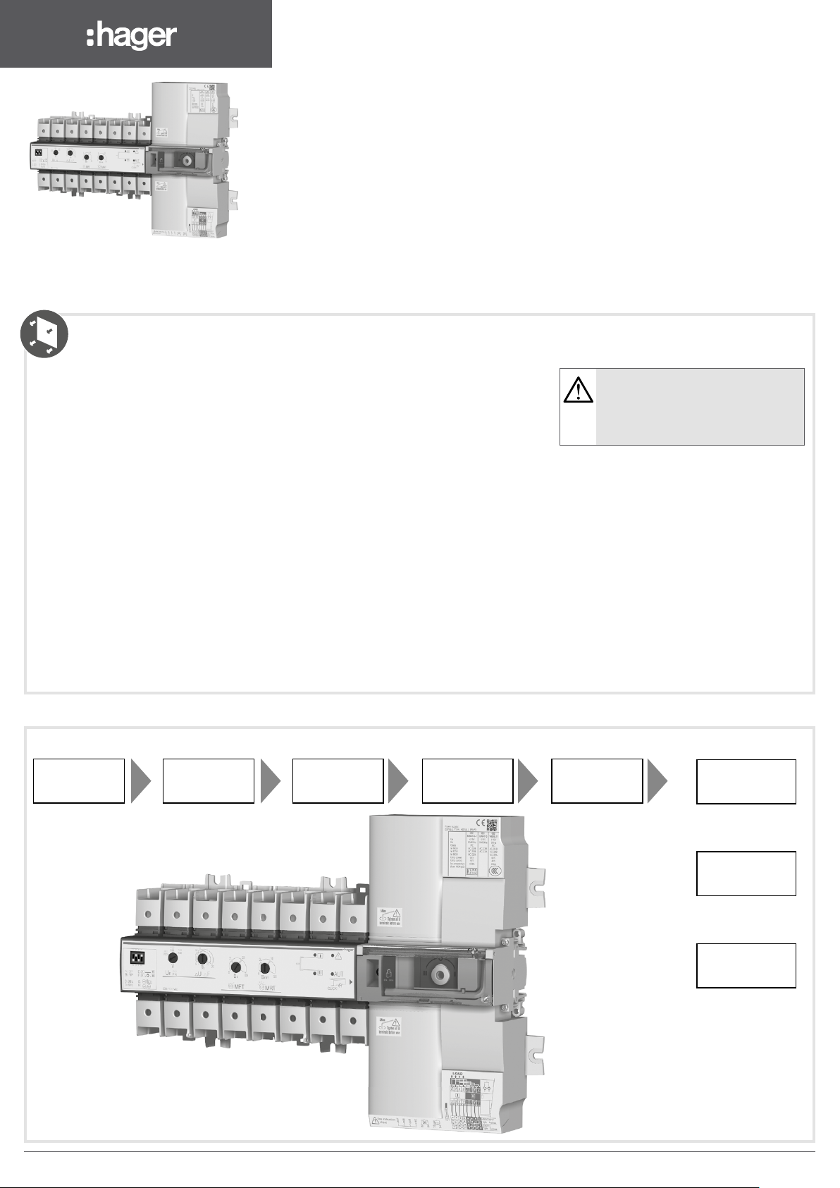
HIC4xxA
Automatic Transfer Switching
z
Equipment 20 A - 160 A (4P)
Preliminary operations
Check the following upon delivery and after removal of
the packaging:
• Packaging and contents are in good condition.
• The product reference corresponds to the order.
• Contents should include:
- 1 HIC4xxA
- 1 Emergency handle extension rod
- 1 Set of terminals
- Quick Start instruction sheet
Accessories
• Bridging bars
• Voltage sensing and power supply tap.
• Terminal shrouds.
• Auxilliary contact block.
• Sealable cover.
This Quick Start is intended for personnel trained in the
installation and commissioning of this product. For
further details refer to the product instruction manual
available on www.hager.com.
This product must always be installed and
commissioned by quali ed and approved personnel.
Maintenance and servicing operations should be
Installation and Commissioning
Step 1
Cabinet / Back
Plate Installation
Step 2
Connecting the
power section
performed by trained and authorised personnel.
Do not handle any control or power cables connected
to the product when voltage may be, or may become
present on the product, directly through the mains or
indirectly through external circuits.
Always use an appropriate voltage detection device to
con rm the absence of voltage.
Ensure that no metal objects are allowed to fall in the
cabinet (risk of electrical arcing).
Failure to observe good enginering practises as well as to
follow these safety instructions may expose the user and
others to serious injury or death.
Step 3
Control / Aux
Power terminal
connections
Step 4
Check
Risk of electrocution, burns or injury to
persons and / or damage to equipment.
Risk of damaging the device In case the
product is dropped or damaged in any way
it is recommended to replace the complete
product.
Step 5
PROGRAMMING
Step 6A
Automatic
Operation
Step 6B
Emergency Manual
Operation
Step 6C
Padlocking
6LE003168Ad1
Page 2
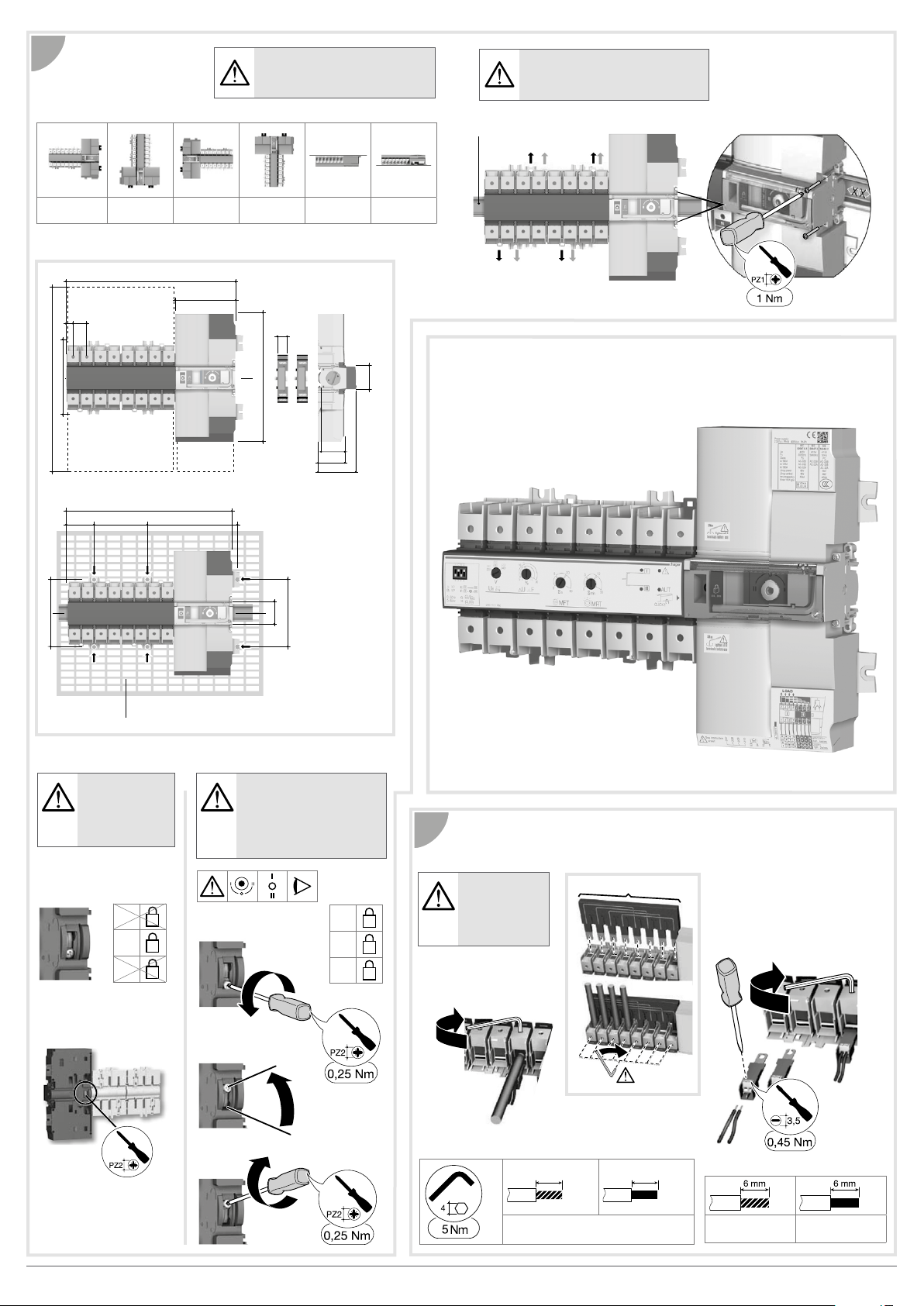
Installation
324
x2
X8
1
Ensure that the product is installed
on a fl at rigid surface
Recommended orientation
Recommended Ok Ok Ok Ok Ok
116
26
13
18
Tighten to avoid movement on the
DIN rail
DIN RAIL IEC 60715
.
Ok
143
350
52 104 176
131,5
326
6 mounting brackets 6x M6 screw - 2,5 Nm
Padlocking con guration
The HIC4xxA is
delivered with
padlocking
con gured to the
O position.
46
53
45
73,5
245
MAX : 2
47
131,5
To allow padlocking in all
positions (I - O - II), con gure
the HIC4xxA as follows
before installation. (Screw
is located at the back of the
product).
Power Terminal Connections
2
2
O
It is essential
to tighten
I
Step 1
I
all terminals
including those
not being used.
Voltage taps provide 2x ≤ 1.5 mm
connections.
They can be tted in any terminals on the
source supply side.
Do not use on the load side when
equipped with a bridging bar.
O
II
II
Step 2
Step 3
x2
Source supply side
Load side bridging bar
125A: HZI400
160A: HZI401
15 mm
10 mm2 to 70 mm
15 mm
2
0,5 mm2 to 1,5 mm20,5 mm2 to 2,5 mm
6LE003168Ad2
2
Page 3
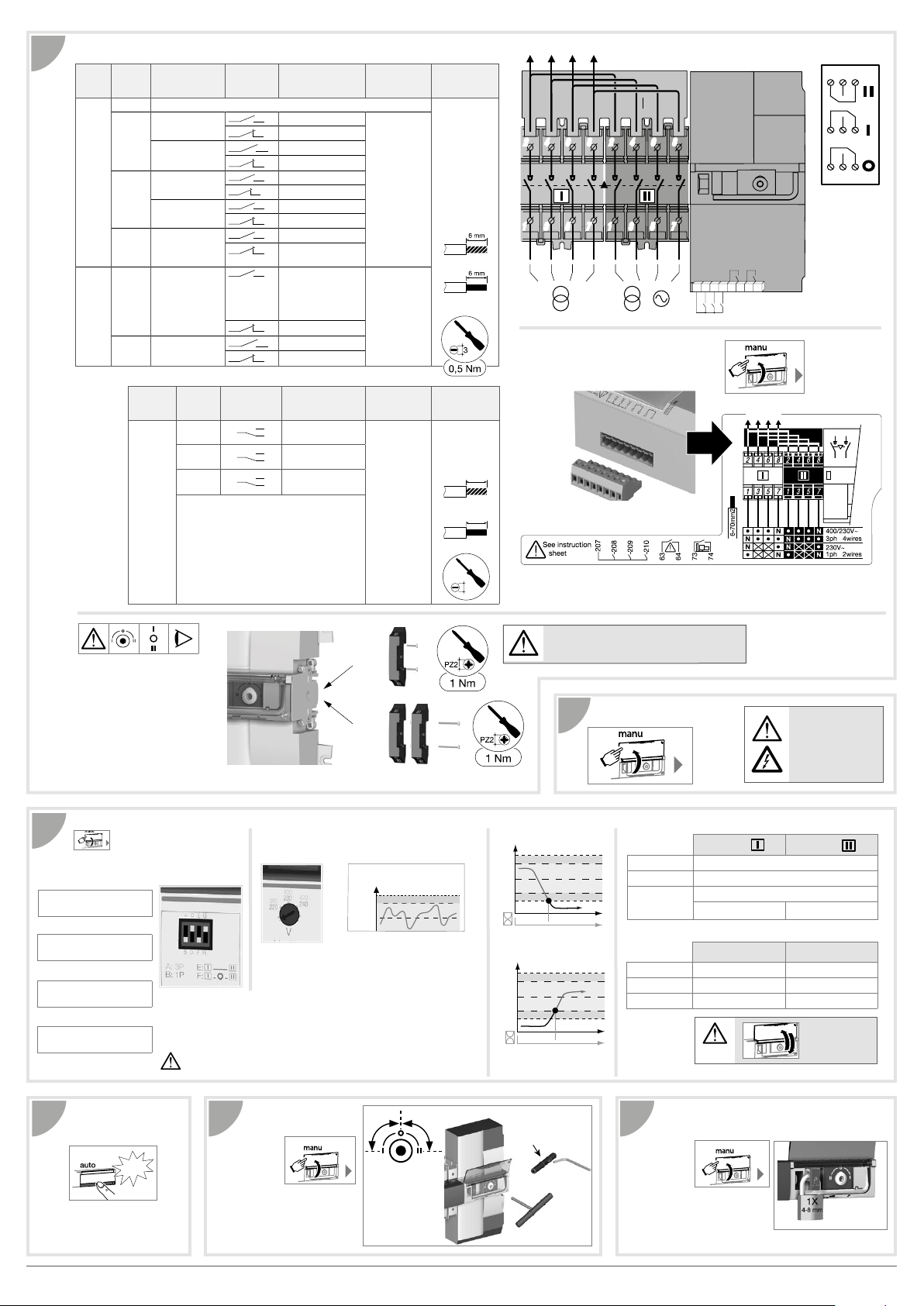
Control / Aux power terminals and wiring
HYST
+∆U/
+∆F
Un
3
Type Terminal
Inputs 207 Common
Outputs 63 / 64 O1Network/Network or
Application Status of the
no.
208I1Network/Network
Network/Genset
209I2Network/Network
Network/Genset
210I3Network/Network or
Network/Generating
set
Network/Generating
set
73 / 74 O2Network/Genset.
contact
Description Output
With priority
Without priority
Automatic retransfer
Manual Retransfer
Source priority 1
Source priority 2
Stop the test on load
Test on load
AUTO mode
Automatic mode
inhibition
Product not available :
- Manual mode
- Command default
- Electronic default
- No source
Product available
No start command genset
Generating set starting
characteristics
Dry potential free
contact
Resistive load
2A 30 Vdc
0.5A 230Vac
Pmax :
60W or 125VA
Umax :
30Vdc or 230Vac
Recommended
connection
cross-section
stranded :
0,5 to 1,5 mm²
rigid :
0,5 to 2,5 mm²
0,5 mm2 to 1,5 mm
0,5 mm2 to 2,5 mm2
LOAD
2 4 6
246 8
1
1357
2
Ensure that the product is in Manual Mode
(front cover open).
8
2 4 6
246 8
5 7
3
1
3
1357
5 7
/
8
207208209210
I1 I2 I3
O1 O2
63 64 73 74
5 A AC1 / DC1
250 Vac / 30Vdc
22 24 21
11 14 12
01 04 02
Auxiliary contacts:
Fitting of auxiliary contacts:
6HZI300.
To t an AC, the switch must rst
be put in position O. An auxiliary
contact module comprises: one
NO / NC changeover contact for
each position (I-O-II).
To install use the long screws
supplied with the module.
PROGRAMMING
5
(
Manual operation)
Deep switch settings
&
Type of network: A-B
A: 3P
B: 1P
Frequency: C-D
C: 50Hz
D: 60Hz
Stop in 0 position: E-F
E: No stop in 0 position
F: 2s stop in 0 position
Type of application: G-H
G: Network - Genset
H: Network - Network
Type Terminal
Auxiliary
contact
block
HZI300
no.
11/12/14
21/22/24
01/02/04
Status of
thecontact
11
21
01
Description Output
Changeover switch
14
in position I
12
Changeover switch
24
in position II
22
Changeover switch
04
in position 0
02
characteristics
250Vac 5A AC1
30 Vdc 5A DC1
10
20
Source voltage supply conguration
é "
230/400 Vac version
Un (P-P):
380-420 Vac
Un (P-N):
220-240 Vac
The LED signalling and operation is only active when the product supply is
available. To set the dip switches, it is necessary to open the Auto/Manual
cover. Commissioning must always result in having at least 1 LED source
available on. (Therefore, the voltage and frequency must be within the dened
thresholds).
Any action on the potentiometers will change the settings, even when
the cover is closed.
HYST: 20% of ∆U/F settings
ΔU 5%/ ΔU20%
ΔF 3%/ ΔF 10%
Recommended
connection
cross-section
stranded :
0,5 to 1,5 mm²
rigid :
0,5 to 2,5 mm²
10 mm
0,5 mm2 to 1,5 mm
10 mm
0,5 mm2 to 2,5 mm2
2,5
2
Timer settings
Loss of priority
source timer
U/F
MFT: 0-30 sec
Return of priority
source timer
U/F
MRT: 0-30 min.
Use 20 mm screws for 1 module
Use 35 mm screws for 2 modules
4
Check
LED info
'
LED ON available
LED OFF missing or out of range
LED blinking
LED ON Fault Auto mode
LED OFF Product OK Manual mode
LED blinking Wait Manual retransfer
- a timer is counting down
- Test mode
MFT
[HYST]
[HYST]
MRT
LOAD
Whilst in manual
mode, check the
wiring and if ok
power up the
product.
Source availability LED's
Source
Fault and state of the product LED's
q
Source
AUT
Fault Reset
Automatic
6A 6B
operation
Click!
Close the front cover as shown
to put the product into automatic
mode.
Manual
operation
Open the front
cover as shown
to put into
manual mode.
Use the handle situated in the
front panel under the cover to
operate the transfer switch.
Check the changeover switch
position on the indicator before
operating.
90°
To simplify
operation use
the handle
with the
extension
provided.
90°
Extension
(Max 8 Mm)
Padlocking mode
6C
In order to
padlock put
the product in
manual mode.
Pull the locking
mechanism and insert a padlock
as shown.
As standard padlocking in the O
position. Congurable to I - O - II
(see step 1).
6LE003168Ad3
Page 4
535443D
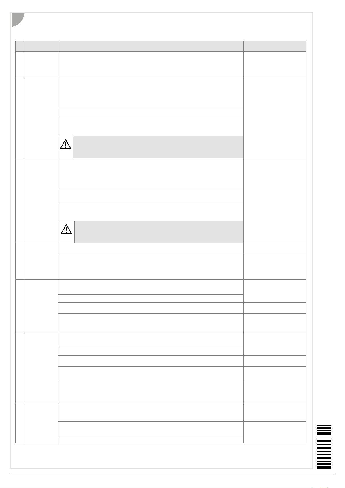
Troubleshooting guide
w
7
Symptoms Action to be carried out Expected results
Adjusment
1
potentiometers of
the rated voltage
and frequency
and voltage
thresholds
The "Priority
2
SOURCE
Availability" LED
does not come on
The "Emergency
3
SOURCE
Availability" LED
does not come on
The product
4
remains switched
off after the
Priority SOURCE
is lost
The product does
5
not switch over
after the Priority
SOURCE is lost
The product does
6
not switch over
when the Priority
SOURCE is
restored
Return to
7
Priority SOURCE
has been
executed, but
the Emergency
Source (for
a Generator)
continues to
operate
Check for a voltage of 176 to 288 Vac on the supply terminals:
• 230 / 400 Vac model :
- Terminals 1-7 correspond to SOURCE 1
- Terminals 1-7 correspond to SOURCE 2
Check the following parameters:
• the type of network => 3P (DIP Switch 1 on position A)
• frequency => 50 Hz (DIP Switch 2 on position C)
• the nominal voltage => with a multimeter, measure the voltage accross the terminals and report the value on the
Check the thresholds and hysteresis of rated voltages (m U) and frequencies (m F) and report them on the
corresponding potentiometer
If using an Auto transformer - proceed as follows upon 1st switching on
• Step 1: HIC4xxA must be connected to a three-phase + neutral network (4NBL) for setting the neutral position.
Neutral position is detected upon rst switching on
• Step 2: Connect the autotransformers. Warning: Neutral must be connected on the same side as in step 1
How to reset the neutral position:
• Step 1: Open the cover
• Step 2 : Set DIP Switch 1 from 3P to 1P
• Step 3 : Set DIP Switch 1 from 1P to 3P
• Step 4 : Close the cover
Check the following parameters:
• the type of network => 3P (DIP Switch 1 on position A)
• frequency => 50 Hz (DIP Switch 2 on position C)
• the nominal voltage => with a multimeter, measure the voltage accross the terminals and report the value on the
CAUTION: a Generator operating off load can generate a Fr and a U lower than the nominal values:
Check the thresholds and hysteresis of rated voltages (m U) and frequencies (m F) and report them on the
corresponding potentiometer.
If using an Auto transformer - proceed as follows upon 1st switching on
• Step 1: HIC4xxA must be connected to a three-phase + neutral network (4NBL) for setting the neutral position.
Neutral position is detected upon rst switching on.
• Step 2: Connect the autotransformers. Warning: Neutral must be connected on the side dened in Step 1
How to reset the neutral position:
• Step 1: Open the cover
• Step 2 : Set DIP Switch 1 from 3P to 1P
• Step 3 : Set DIP Switch 1 from 1P to 3P
• Step 4 : Close the cover
Check if voltage is between 176 to 288 VAC across the power supply terminals of emergency SOURCE :
• 230 / 400 Vac model: - Terminals 1-7 corresponding to the Emergency Source
In case of transformer/ Genset, check that FT timer (Main Failure Timer) has nished counting down.
• Use a stopwatch.
• Start the stopwatch when the product has lost its Priority SOURCE.
- Contact 73 - 74 must be closed after 60s max (M-G application )
- GENSET run command = Contact 73-74 Closed
- GENSET stop command = Contact 73-74 Opened
Check that the product is not in manual mode:
• Automatic mode = Cover closed
• Manual mode = Cover open
Check that automatic operation has not been inhibited by an external order (terminals 207-210)
Check the status of led « Emergency SOURCE availability ».If it is off, refer to the symptom concerned (higher in the
list)
In case of Transformer/ Transformer, check the setting of FT timer (Main Failure Timer). The duration of this time
delay is between 0 and 60s. If necessary, use a stopwatch to check switching to SOURCE after FT countdown
Check that the product is not in manual mode:
- Automatic mode = Cover closed
- Manual mode = Cover open
Check that automatic operation has not been inhibited by an external order (terminals 207-210).
Check the state of the "Priority Source Availability" LED. If it is off, refer to the symptom concerned (higher in the list) The "AUT" and "Emergency
Check the setting of RT timer (Main Return Timer). The duration of this delay is between 0 and 30 min. Use a
stopwatch to check the switch to Priority SOURCE after the RT timer
Check that the "manual retransfer" function is not active*
• Retransfer mode activated = Contact 207-208 closed
• Retransfer mode desactivated = Contact 207-208 open
* if this function is not required
Check CDT timer (Cool Down Timer) has nished counting down - Fixed time delay:4 min
• Use a stopwatch.
- Start the stopwatch when the product has switched over to the Priority SOURCE.
- Contact 73-74 must be open after time delay CDT has nished counting down
Check that the product is not in Automatic mode:
- Automatic mode = Cover close
- Manual mode = Cover open
Check that automatic operation has not been inhibited by external control commands (terminals 207-210)
1P (DIP Switch 1 on position B)
60 Hz (DIP Switch 2 on position D)
potentiometer
1P (DIP Switch 1 on position B)
60 Hz (DIP Switch 2 on position D)
potentiometer
The AUT LED is lit (if the cover is
closed)
The "Priority SOURCE Availability"
LED is lit
The "Emergency SOURCE
Availability" LED is lit
The "AUT" LED is lit
The Genset works and the LED
"Emergency Source Disponibility"
is lit
The "AUT" LED is lit
The "AUT" and "Emergency
SOURCE Availability" LEDs are lit
At the end of the time delay, the
product switches to mechanical
position 0, and to emergency
SOURCE
The "AUT" LED is lit
SOURCE Availability" LEDs are lit
At the end of the time delay, the
product switches to mechanical
position 0, and to priority SOURCE
Contact 207-208 must be open to
enable switching to priority SOURCE
The GenSet switches off and led "
Emergency SOURCE availability"
is OFF”
The "AUT" LED is lit
Hager Electro S.A.S., Boulevard d'Europe, B.P. 3, 67215 OBERNAI CEDEX, France - www.hager.com OCOM 129068Hager 01.19 6LE003168Ad4
535443D / Printing size: A3 / Recto-verso / Black / 90g/m² / Final size A4
 Loading...