

Page 1

1 6E 6504.c
6E 6504.c
A2
1
816
A1
15
2
4
6
8
10
1
0,1s
1s
0,1mn
1mn
0,
1h
1h
E
ZN004
EZN004
¢
£
§
•
¶
ß
®
©
FR
DE
T
IN
(B1)
OUT
(15 - 18)
LED
GB
Notice d’instructions
Relais temporisé
calibreur d’impulsion
Bedienungsanleitung
Impulsformer
User instructions
Timer
1 2 3
2
4
6
8
10
1
0,1
s
1s
0
,
1mn
1mn
0,1h
1h
EZN002
0,1s
1s
0,1mn
1mn
0,1h
1h
2
4
6
8
10
1
LED
Gebruiksaanwijzing
Verklikker met
asymmetrische regeling
NL
L / +
N / -
18A116
15
A2 B1
16
18
IN
15
4
EZN004
Pouvoir de coupure min. :
100 mA / 12 V
Température de fonctionnement :
-10 °C... +50 °C
Température de stockage :
-20 °C... +70 °C
Capacité de raccordement :
souple : 1 □...6
□
rigide : 1,5 □...10
□
Raccordement électrique
➃
alimentation en 12 à 230 V 쓒
12 à 48 V
Nota : n’est pas destiné à être connecté à un
circuit d’alimentation de sécurité à très basse
tension (TBTS).
Spécifications techniques
Alimentation :
entre A1 et A2 : 12 à 230 V 쓒 +10% -10%
12 à 48 V +10% -10%
Tension de commande : idem alimentation
Fréquence : 50/60 Hz
Sortie : 1 inverseur libre de potentiel
Pouvoir de coupure max. :
AC1 : 8 A / 230 V 50 000 cycles
Incandescence : 450 W 50 000 cycles
Fluo non compensé : 600 W 50 000 cycles
Charge inductive cos
φ
0,6 : 5 A 100 000 cycles.
Minimale Schaltleistung:
100 mA / 12 V
Umgebungstemperatur:
-10 °C... +50 °C
Lagerungstemperatur:
-20 °C... +70 °C
Anschlußkapazität:
mehdrähtig: 1
□
...6
□
eindrätig: 1,5 □...10
□
Elektrischer Anschluß
➃
Spannung von 12 bis 230 V 쓒
12 bis 48 V
Anmerkung: nicht geeignet zum Anschluss an
Sicherheitkleinspannungskreise (SELV).
Technische Daten
Versorgungsspannung:
zwischen A1 und A2: 12 bis 230 V 쓒 +10% -10%
12 bis 48 V +10% -10%
Steuerspannung: gleich Verzorgungsspannung
Frequenz: 50/60 Hz
Ausgang: 1 Wechsler potentialfrei
Schaltleistung:
AC1: 8 A / 230 V 50 000 Zyklen
Glühlampen: 450 W 50 000 Zyklen
Leuchtstofflampen: 600 W 50 000 Zyklen
Induktive Last cos
φ
0,6: 5 A 100 000 Zyklen.
Min. breaking capacity:
100 mA / 12 V
Working temperature:
-10 °C... +50 °C
Storage temperature:
-20 °C... +70 °C
Connection capacity:
flexible: 1 □...6
□
rigid: 1,5 □...10
□
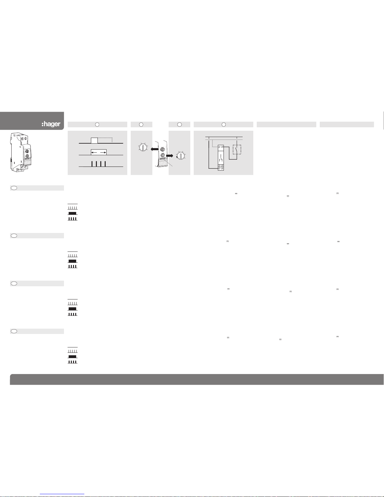
Electrical connection
➃
supply from 12 to 230 V 쓒
12 to 48 V
➄
supply from 12 V and 쓒
Note: not suitable to be connected to a safety
extra low voltage (SELV) circuit.
Technical specifications
Supply:
between A1 and A2: 12 to 230 V 쓒 +10% -10%
12 to 48 V +10% -10%
Control voltage: identical to the supply
Frequency: 50/60 Hz
Output: 1 volt free changeover contact
Max. capacity:
AC1: switching 8 A / 230 V 50 000 cycles
Incandescent lights: 450 W 50 000 cycles
Non compensated fluorescent: 600 W 50 000 cycles
Inductive load cos
φ
0,6: 5 A 100 000 cycles.
➀
Diagramme de fonctionnement
IN : commande
OUT : sortie
Signification du clignotement de la LED :
- relais de sortie ouvert, pas de
temporisation en cours
- relais de sortie ouvert, temporisation en
cours
- relais de sortie fermé, pas de
temporisation en cours
- relais de sortie fermé, temporisation en
cours.
Réglage de la temporisation
De 0,1 s. à 10 h.
➁
réglage de la gamme de temporisation
➂
réglage fin de la temporisation
La position du sélecteur ➁multipliée par la
valeur indiquée par le potentiomètre ➂=
temporisation T.
Exemple : T = 0,1 min. x 7 (0,1 min. = 6 s.)
T = 6 s. x 7 = 42 s.
➀
Funktionsdiagramm
IN: Steuerung
OUT: Ausgangzustand
Funktionsanzeige durch LED:
- Ausgang im Ruhezustand, kein
Zeitablauf
- Ausgang im Ruhezustand, Zeit läuft
- Ausgang im Arbeitszustand, kein
Zeitablauf
- Ausgang im Arbeitszustand, Zeit läuft.
Einstellung der Verzögerungszeit
Von 0,1 s. bis 10 h.
➁
Einstellung des Verzögerungsbereiches
➂
Feineinstellung der Verzögerungszeit
Die Position des Verzögerungswahlschalters
➁
multipliziert mit der Potentiometereinstellung ➂= Verzögerungszeit T.
Beispiel: T = 0,1 Min. x 7 (0,1 Min. = 6 s.)
T = 6 s. x 7 = 42 s.
➀
Working diagram
IN: control
OUT: output
Reason of the LED flashing:
- output relay open, time delay inactive
- output relay open, time delay active
- output relay closed, time delay inactive
- output relay closed, time delay active.
Time delay setting
From 0,1 s. to 10 h.
➁
time setting
➂
multiple of time setting
The position of the selector ➁multiplied by the
value indicated on the potentiometer ➂gives the
value of the delay T.
Example: T = 0.1 min. x 7 (0.1 min. = 6 s.)
T = 6 s. x 7 = 42 s.
Min. scheidingsvermogen:
100 mA / 12 V
Werkingstemperatuur:
-10 °C... +50 °C
Stockagetemperatuur:
-20 °C... +70 °C
Ansluiting:
soepele: 1
□
...6
□
stijve: 1,5 □...10
□
Elektrische aansluiting
➃
voeding 12 tot 230 V 쓒
12 tot 48 V
Nota: mag niet aangesloten worden op een
veiligheidsvoedingskring met zeer lage
spanning (ZLVS).
Technische specificaties
Voeding:
tussen A1 en A2: 12 tot 230 V 쓒 +10% -10%
12 tot 48 V +10% -10%
Frequentie: 50/60 Hz
Uitgang: 1 omschakelaar vrij van potentieel
Max. scheidingsvermogen:
AC1: 8 A / 230 V 50 000 cyclussen
Gloeilamp: 450 W 50 000 cyclussen
Fluo niet gecompenseerd: 600 W 50 000 cyclussen
Inductieve belasting cos
φ
0,6: 5 A 100 000
cyclussen.
➀
Werkingsdiagram
IN: bediening
OUT: uitgang
Verklaring van het knipperen van de LED:
- uitgangsrelais open, tijdinstelling niet
geactiveerd
- uitgangsrelais open, tijdinstelling
geactiveerd
- uitgangsrelais gesloten, geen
tijdinstelling geactiveerd
- uitgangsrelais gesloten, tijdinstelling
geactiveerd.
Regeling van de tijdinstelling
Van 0,1 s. tot 10 u.
➁
regeling van het gamma van tijdinstelling
➂
fijnregeling van de tijdinstelling
De stand van de keuzeschakelaar ➁vermenigvuldigd met de door de potentiometer aangegeven
waarde ➂= tijdinstelling T.
Voorbeeld: T = 0,1 Min. x 7 (0,1 Min. = 6 s.)
T = 6 s. x 7 = 42 s.
http://waterheatertimer.org/Hagar-timers-and-manuals.html
Page 2
L / +
N / -
18A116
15
A2 B1
16
18
IN
15
EZN001
Hager SAS - 132 bld d’Europe - BP78 - 67 212 Obernai cedex (FRANCE) - Tél. +333 88 49 50 50 - www.hagergroup.net2 6E 6504.c
Hager 10.2009
6E 6504.c
A2
1
816
A1
15
2
4
6
8
10
1
0,1s
1s
0,1mn
1mn
0,
1h
1h
E
ZN004
¢
£
§
•
¶
ß
®
©
T
IN (B1)
OUT
(15 - 18)
LED
1 2 3
2
4
6
8
10
1
0,1s
1s
0
,1mn
1mn
0,1h
1h
EZN002
0,1s
1s
0,1mn
1mn
0,1h
1h
2
4
6
8
10
1
LED
4
IT
Istruzioni d’impiego
Relé temporizzatori
regolatori d’impulsi
Hoja de instrucciones
Relé temporizado
temporizador
Instruções de Montagem
Oδηγίες χρήσεως
Χρονικ ρελέ
ρύθμισης χρνου
λειτουργίας
Relé temporizado
calibrador de impulsos
ES
PT
GR
EZN004
Portata minima del contatto:
100 mA / 12 V
Temperatura di funzionamento:
-10 °C... +50 °C
Temperatura di stoccaggio:
-20 °C... +70 °C
Capacita di connessione:
cavi flessibili: 1 □...6
□
cavi rigidi: 1,5 □...10
□
Collegamento elettrico
➃
tensione nominale: da 12 a 230 V 쓒
12 a 48 V
Nota: non adatto per essere collegato a un
circuito d’alimentazione a bassissima tensione di
sicurezza (SELV).
Caratteristiche tecniche
Tensione nominale:
tra A1 e A2: da 12 a 230 V 쓒 +10% -10%
12 a 48 V +10% -10%
Tensione de comando: come tensione nominale
Frequenza: 50/60 Hz
Uscita: 1 contatto in scambio libero di potenziale
Portata massima del contatto:
AC1: 8 A / 230 V 50 000 cicli
Lampade incandescenti: 450 W 50 000 cicli
Fluo non rifasate: 600 W 50 000 cicli
Carico induttivo cos
φ
0,6: 5 A 100 000 cicli.
➀
Diagramma di funzionamento
IN: comando
OUT: uscita
Significato del LED lampeggiante:
- relé d’uscita aperto, nessuna
temporizzazione in corso
- relé d’uscita aperto, temporizzazione
in corso
- relé d’uscita chiuso, nessuna
temporizzazione in corso
- relé d’uscita chiuso, temporizzazione
in corso.
Regolazione della temporizzazione
Da 0,1 s. a 10 h.
➁
scelta della scala dei tempi
➂
regolazione fine
La posizione del selettore ➁moltiplicata per la
posizione del selettore
➂
indica la temporizzazione
impostata T.
Esempio: T = 0,1 min. x 7 (0,1 min. = 6 s.)
T = 6 s. x 7 = 42 s.
Poder de corte mínimo:
100 mA / 12 V
Temperatura de funcionamiento:
-10 °C... +50 °C
Temperatura de almacenaje:
-20 °C... +70 °C
Capacidad de conexión:
cable flexible: 1
□
...6
□
cable rígido: 1,5 □...10
□
Conexión eléctrica
➃
alimentación 12 a 230 V 쓒
12 a 48 V
Nota: no está destinado a conectarse a un circuito
de alimentación de Muy Baja Tensión de Seguridad
(MBTS).
Especificaciones técnicas
Alimentación:
entre A1 y A2: 12 a 230 V 쓒 +10% -10%
12 a 48 V +10% -10%
Tensión de mando: idem alimentación
Frecuencia: 50/60 Hz
Salida: 1 contacto conmutado libre de potencial
Poder de corte máximo:
AC1: 8 A / 230 V 50 000 ciclos
Incandescencia: 450 W 50 000 ciclos
Fluorescencia no compensada: 600 W 50 000 ciclos
Carga inductiva cos
φ
0,6: 5 A 100 000 ciclos.
➀
Diagrama de funcionamiento
IN: mando
OUT: salida
Significado de la intermitencia del LED:
- relé de salida abierto, temporizador
parado.
- relé de salida abierto, temporizador
en curso.
- relé de salida cerrado, temporizador
parado.
- relé de salida cerrado, temporizador
en curso.
Regulación de la temporización
De 0,1 s. a 10 h.
➁
regulación de la gama de temporización
➂
regulación del tiempo de la temporización
La posición del selector ➁por el valor indicado en
el potenciómetro ➂= temporización T.
Ejemplo: T = 0,1 minuto x 7 (0,1 minuto = 6 s.)
T = 6 s. x 7 = 42 s.
Poder de corte minímo:
100 mA / 12 V
Temperatura de funcionamento:
-10 °C... +50 °C
Temperatura de armazenamento:
-20 °C... +70 °C
Capacidade de ligação:
fio flexível: 1
□
...6
□
fio rígido: 1,5 □...10
□
Ligações eléctricas
➃
alimentação de 12 V a 230 V
쓒
12 a 48 V
Nota: não esta permitida a conexão a un circuito
de alimentação tipo muito baixa tensão (MBT).
Especificações técnicas
Alimentação:
entre A1 e A2: 12 a 230 V 쓒 +10% -10%
12 a 48 V +10% -10%
Tensão de comando: identica alimentação
Frequencia: 50/60Hz
Saída: 1 contacto inversor livre de potencial
Poder de corte máximo:
AC1: 8 A / 230V 50 000 ciclos
Incandescente: 450 W 50 000 ciclos
Fluorescentes não compensadas: 600 W 50 000 ciclos
Carga indutiva cos
φ
0,6: 5 A 100 000 ciclos.
➀
Diagrama de funcionamento
IN: comando
OUT: saída
Interpretação da forma de piscar do LED:
- relé de saída aberto, sem tempo
rização a decorrer
- relé de saída aberto, temporização
a decorrer,
- relé de saída fechado, sem tempo
rização a decorrer,
- relé de saída fechado,
temporização a decorrer.
Regulação da temporização
De 0,1 s. a 10 h.
➁
regulação da gama de temporização
➂
regulação do fim da temporização
A posição do selector ➁multiplicada pelo valor
indicado pelo do potenciómetro ➂= temporização T.
Exemplo: T = 0,1 min. x 7 (0,1 min. = 6 s.)
T = 6 s. x 7 = 42 s.
➀
Διάγραμμα λειτουργίας
IN: εντολή
OUT: έξοδος
Λειτουργία ενδεικτικού LED:
- επαφή εξδου ανοικτή, δε μετρά ο
χρνος καθυστέρησης
- επαφή εξδου ανοικτή, μετρά ο
χρνος καθυστέρησης
- επαφή εξδου κλειστή, δε μετρά ο
χρνος καθυστέρησης
- επαφή εξδου κλειστή, μετρά ο
χρνος καθυστέρησης.
Ελάχιστη δυναττητα ενεγοποίησης:
100 mA / 12 V
Θερμοκρασίες λειτουργίας:
-10 °C έως +50 °C
Θερμοκρασίες αποθήκευσης:
-20 °C έως +70 °C
Συνδέσεις καλωδίων:
εύκαμπτο:1
□
...6
□
μονκλωνο: 1,5 □...10
□
Ηλεκτρική συνδεσμολογία
➃
τροφοδοσία σε 12 V - 230 V 쓒
12 - 48 V
Σημείωση: δε μπορεί να συνδεθεί σε
κύκλωμ πολύ χαμηλής τάσης.
Τεχνικές προδιαγραφές
Τροφοδοσία:
(A1, A2): 12 - 230 V 쓒 με ανοχές +10% -10%
12 - 48 V με ανοχές +10% -10%
Τάση κυκλώματος ελέγχου ίση με την τάση
λειτουργίας
Συχντητα: 50/60 Hz
Έξοδος: μία επαφή χωρίς περιορισμ τάσης
χρνος ζωής:
AC1: 8 A / 230V 50 000 κύκλοι λειτουργίας (κ.λ.)
με λαμπτήρες πυρακτώσεως: 450 W 50 000 κ.λ.
με λαμπτήρες φθορισμού μη αντισταθ: 600 W
50 000 κ.λ.
με επαγωγικ φορτίο cos
φ
0,6: 5 A 100 000 κ.λ.
Ρύθμιση
Απ 0,1 s έως 10 h.
➁
ρύθμιση χρνου
➂
πολλαπλάσιο του χρνου ρύθμισης
Η ρύθμιση του επιλογέα➁πολλαπλασιαζμενη
με την ένδειξη τουποτενσιμετρου➂δείχνει
το χρνο καθυστέρησης Τ.
Παράδειγμα:
T = 0.1 min. x 7 (0.1 min. = 6 s.)
T = 6 s. x 7 = 42 s.
 Loading...