

Page 1
➀
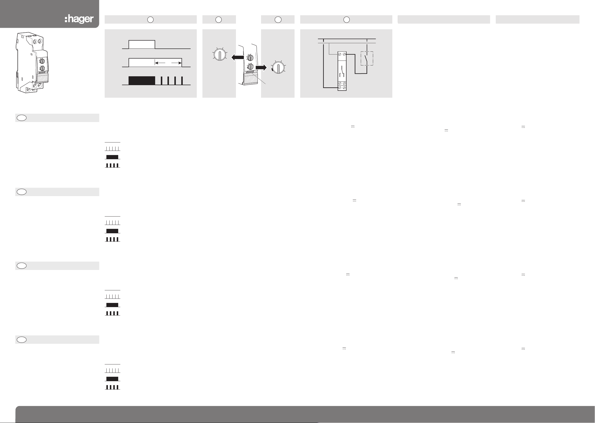
Werkingsdiagram
IN: bediening
OUT: uitgang
Verklaring van het knipperen van de LED:
- uitgangsrelais open, tijdinstelling niet
geactiveerd
- uitgangsrelais open, tijdinstelling
geactiveerd
- uitgangsrelais gesloten, geen
tijdinstelling geactiveerd
- uitgangsrelais gesloten, tijdinstelling
geactiveerd.
➀
Working diagram
IN: control
OUT: output
Reason of the LED flashing:
- output relay open, time delay inactive
- output relay open, time delay active
- output relay closed, time delay inactive
- output relay closed, time delay active.
➀
Funktionsdiagramm
IN: Steuerung
OUT: Ausgangzustand
Funktionsanzeige durch LED:
- Ausgang im Ruhezustand, kein
Zeitablauf
- Ausgang im Ruhezustand, Zeit läuft
- Ausgang im Arbeitszustand, kein
Zeitablauf
- Ausgang im Arbeitszustand, Zeit läuft.
➀
Diagramme de fonctionnement
IN : commande
OUT : sortie
Signification du clignotement de la LED :
- relais de sortie ouvert, pas de
temporisation en cours
- relais de sortie ouvert, temporisation en
cours
- relais de sortie fermé, pas de
temporisation en cours
- relais de sortie fermé, temporisation en
cours.
1 6E 6502.c
6E 6502.c
A2
1
816
A1
15
2
4
6
8
10
1
0,1s
1s
0,1mn
1mn
0,
1h
1h
E
ZN002
EZN002
¢
£
§
•
¶
ß
®
©
1 2 3
2
4
6
8
10
1
0,
1
s
1s
0
,1mn
1mn
0,1h
1h
EZN002
0,1s
1s
0,1mn
1mn
0,1h
1h
2
4
6
8
10
1
LED
4
EZN002
Pouvoir de coupure min. :
100 mA / 12 V
Température de fonctionnement :
-10 °C... +50 °C
Température de stockage :
-20 °C... +70 °C
Capacité de raccordement :
souple : 1
□
...6
□
rigide : 1,5 □...10
□
Raccordement électrique
➃
alimentation en 12 à 230 V 쓒
12 à 48 V
Nota : n’est pas destiné à être connecté à un
circuit d’alimentation de sécurité à très basse
tension (TBTS).
Spécifications techniques
Alimentation :
entre A1 et A2 : 12 à 230 V 쓒 +10% -10%
12 à 48 V +10% -10%
Tension de commande : idem alimentation
Fréquence : 50/60 Hz
Sortie : 1 inverseur libre de potentiel
Pouvoir de coupure max. :
AC1 : 8 A / 230 V 50 000 cycles
Incandescence : 450 W 50 000 cycles
Fluo non compensé : 600 W 50 000 cycles
Charge inductive cos
φ
0,6 : 5 A 100 000 cycles.
Minimale Schaltleistung:
100 mA / 12 V
Umgebungstemperatur:
-10 °C... +50 °C
Lagerungstemperatur:
-20 °C... +70 °C
Anschlußkapazität:
mehdrähtig: 1
□
...6
□
eindrätig: 1,5 □...10
□
Elektrischer Anschluß
➃
Spannung von 12 bis 230 V 쓒
12 bis 48 V
Anmerkung: nicht geeignet zum Anschluss
an Sicherheitkleinspannungskreise (SELV).
Technische Daten
Versorgungsspannung:
zwischen A1 und A2: 12 bis 230 V 쓒 +10% -10%
12 bis 48 V +10% -10%
Steuerspannung: gleich Verzorgungsspannung
Frequenz: 50/60 Hz
Ausgang: 1 Wechsler potentialfrei
Schaltleistung:
AC1: 8 A / 230 V 50 000 Zyklen
Glühlampen: 450 W 50 000 Zyklen
Leuchtstofflampen: 600 W 50 000 Zyklen
Induktive Last cos
φ
0,6: 5 A 100 000 Zyklen.
Min. breaking capacity:
100 mA / 12 V
Working temperature:
-10 °C... +50 °C
Storage temperature:
-20 °C... +70 °C
Connection capacity:
flexible: 1 □...6
□
rigid: 1,5 □...10
□
Electrical connection
➃
supply from 12 to 230 V 쓒
12 to 48 V
Note: not suitable to be connected to a safety
extra low voltage (SELV) circuit.
Technical specifications
Supply:
between A1 and A2: 12 to 230 V 쓒 +10% -10%
12 to 48 V +10% -10%
Control voltage: identical to the supply
Frequency: 50/60 Hz
Output: 1 volt free changeover contact
Max. capacity:
AC1: switching 8 A / 230 V 50 000 cycles
Incandescent lights: 450 W 50 000 cycles
Non compensated fluorescent: 600 W 50 000 cycles
Inductive load cos
φ
0,6: 5 A 100 000 cycles.
FR
DE
GB
Réglage de la temporisation
De 0,1 s. à 10 h.
➁
réglage de la gamme de temporisation
➂
réglage fin de la temporisation
La position du sélecteur ➁multipliée par la valeur
indiquée par le potentiomètre ➂= temporisation T.
Exemple : T = 0,1 min. x 7 (0,1 min. = 6 s.)
T = 6 s. x 7 = 42 s.
Notice d’instructions
Relais temporisé
retardé au
déclenchement
Bedienungsanleitung
Rückfallverzögertes
Zeitrelais
User instructions
Delay OFF timer
Einstellung der Verzögerungszeit
Von 0,1 s. bis 10 h.
➁
Einstellung des Verzögerungsbereiches
➂
Feineinstellung der Verzögerungszeit
Die Position des Verzögerungswahlschalters
➁
multipliziert mit der Potentiometer-einstellung
➂
= Verzögerungszeit T.
Beispiel: T = 0,1 Min. x 7 (0,1 Min. = 6 s.)
T = 6 s. x 7 = 42 s.
Time delay setting
From 0,1 s. to 10 h.
➁
time setting
➂
multiple of time setting
The position of the selector ➁multiplied by the
value indicated on the potentiometer ➂gives the
value of the delay T.
Example: T = 0.1 min. x 7 (0.1 min. = 6 s.)
T = 6 s. x 7 = 42 s.
Gebruiksaanwijzing
Min. scheidingsvermogen:
100 mA / 12 V
Werkingstemperatuur:
-10 °C... +50 °C
Stockagetemperatuur:
-20 °C... +70 °C
Ansluiting:
soepele: 1 □...6
□
stijve: 1,5 □...10
□
Elektrische aansluiting
➃
voeding 12 tot 230 V 쓒
12 tot 48 V
Nota: mag niet aangesloten worden op een
veiligheidsvoedingskring met zeer lage
spanning (ZLVS).
Technische specificaties
Voeding:
tussen A1 en A2: 12 tot 230 V 쓒 +10% -10%
12 tot 48 V +10% -10%
Frequentie: 50/60 Hz
Uitgang: 1 omschakelaar vrij van potentieel
Max. scheidingsvermogen:
AC1: 8 A / 230 V 50 000 cyclussen
Gloeilamp: 450 W 50 000 cyclussen
Fluo niet gecompenseerd: 600 W 50 000 cyclussen
Inductieve belasting cos
φ
0,6: 5 A 100 000
cyclussen.
Tijdvertragende relais
bij afschakeling
Regeling van de tijdinstelling
Van 0,1 s. tot 10 u.
➁
regeling van het gamma van tijdinstelling
➂
fijnregeling van de tijdinstelling
De stand van de keuzeschakelaar ➁vermenigvuldigd met de door de potentiometer aangegeven
waarde
➂
= tijdinstelling T.
Voorbeeld: T = 0,1 Min. x 7 (0,1 Min. = 6 s.)
T = 6 s. x 7 = 42 s.
NL
IN (B1)
OUT
(15 - 18)
LED
T
L / +
N / -
A2 B1
15
18A116
18
IN
16
15
 Loading...