

hager domovea TJA450 Installer Manual
domovea server
GB
TJA450
tebis

2
domovea server
Installer manual

Table of contents
1 System presentation . . . . . . . . . . . . . . . . . . . . . . . . . . . . . . . . . . . . . . . . . . . . . . . . . . . . . . . . . . . 4
1.1 Introduction . . . . . . . . . . . . . . . . . . . . . . . . . . . . . . . . . . . . . . . . . . . . . . . . . . . . . . . . . . . . . . . . . . . . . . . . . . . . . 4
1.2 General scheme of domovea System . . . . . . . . . . . . . . . . . . . . . . . . . . . . . . . . . . . 4
1.3 System requirements . . . . . . . . . . . . . . . . . . . . . . . . . . . . . . . . . . . . . . . . . . . . . . . . . . . . . . . . . . . . . . 5
1.4 Hardware installation server TJA450 . . . . . . . . . . . . . . . . . . . . . . . . . . . . . . . . . . . . . 5
1.4.1 Connexion diagramm
1.4.2 Network connexions
Installation behind a DHCP Server
Installation without DHCP Server
1.4.3 TJA4X0 Front Panel
. . . . . . . . . . . . . . . . . . . . . . . . . . . . . . . . . . . . . . . . . . . . . . . . . . . . . . . . . . . . . . . . . . 5
. . . . . . . . . . . . . . . . . . . . . . . . . . . . . . . . . . . . . . . . . . . . . . . . . . . . . . . . . . . . . . . . . . . . 6
. . . . . . . . . . . . . . . . . . . . . . . . . . . . . . . . . . . . . . . . . . . . . . . . 6
. . . . . . . . . . . . . . . . . . . . . . . . . . . . . . . . . . . . . . . . . . . . . . . . . 6
. . . . . . . . . . . . . . . . . . . . . . . . . . . . . . . . . . . . . . . . . . . . . . . . . . . . . . . . . . . . . . . . . . . . . 7
1.5 Installation of client software . . . . . . . . . . . . . . . . . . . . . . . . . . . . . . . . . . . . . . . . . . . . . . . . . 8
1.6 Connect the computer terminal to the server . . . . . . . . . . . . . . . . . . . . . . 8
1.6.1 Behind a router or any other DHCP server
1.6.2 Connection without DHCP server
. . . . . . . . . . . . . . . . . . . . . . . . . . . . . . . . . . . . . . . . . . . . . . . . . 9
. . . . . . . . . . . . . . . . . . . . . . . . . . . . . . . . . . . . 8
2 Configuration tool description . . . . . . . . . . . . . . . . . . . . . . . . . . . . . . . . . . . . . . . 10
2.1 General menu . . . . . . . . . . . . . . . . . . . . . . . . . . . . . . . . . . . . . . . . . . . . . . . . . . . . . . . . . . . . . . . . . . . . . . . . . 10
2.2 Configuration menu . . . . . . . . . . . . . . . . . . . . . . . . . . . . . . . . . . . . . . . . . . . . . . . . . . . . . . . . . . . . . . . 13
3 Start up guide for the Configuration tool . . . . . . . . . . . . . . . . . . . . 14
3.1 Define the structure of the building . . . . . . . . . . . . . . . . . . . . . . . . . . . . . . . . . . . . . 14
3.1.1 Create Groups
. . . . . . . . . . . . . . . . . . . . . . . . . . . . . . . . . . . . . . . . . . . . . . . . . . . . . . . . . . . . . . . . . . . . . . . . . . . 15
3.1.2 Create Devices
. . . . . . . . . . . . . . . . . . . . . . . . . . . . . . . . . . . . . . . . . . . . . . . . . . . . . . . . . . . . . . . . . . . . . . . . . . 15
3.2 KNX Linking . . . . . . . . . . . . . . . . . . . . . . . . . . . . . . . . . . . . . . . . . . . . . . . . . . . . . . . . . . . . . . . . . . . . . . . . . . . . 16
3.2.1 TX100 project
3.2.2 ETS project
. . . . . . . . . . . . . . . . . . . . . . . . . . . . . . . . . . . . . . . . . . . . . . . . . . . . . . . . . . . . . . . . . . . . . . . . . . . . 16
. . . . . . . . . . . . . . . . . . . . . . . . . . . . . . . . . . . . . . . . . . . . . . . . . . . . . . . . . . . . . . . . . . . . . . . . . . . . . . . 20
3.3 Cameras . . . . . . . . . . . . . . . . . . . . . . . . . . . . . . . . . . . . . . . . . . . . . . . . . . . . . . . . . . . . . . . . . . . . . . . . . . . . . . . . . 23
3.3.1 Camera selection
3.3.2 Defining a link to a camera
3.3.3 Camera models import
. . . . . . . . . . . . . . . . . . . . . . . . . . . . . . . . . . . . . . . . . . . . . . . . . . . . . . . . . . . . . . . . . . . . . . 23
. . . . . . . . . . . . . . . . . . . . . . . . . . . . . . . . . . . . . . . . . . . . . . . . . . . . . . . . . 24
. . . . . . . . . . . . . . . . . . . . . . . . . . . . . . . . . . . . . . . . . . . . . . . . . . . . . . . . . . . . . . 24
3.4 Display profiles . . . . . . . . . . . . . . . . . . . . . . . . . . . . . . . . . . . . . . . . . . . . . . . . . . . . . . . . . . . . . . . . . . . . . . 25
3.5 Icons and backgrounds . . . . . . . . . . . . . . . . . . . . . . . . . . . . . . . . . . . . . . . . . . . . . . . . . . . . . . . . . 28
3.6 Automation sequences . . . . . . . . . . . . . . . . . . . . . . . . . . . . . . . . . . . . . . . . . . . . . . . . . . . . . . . . . 29
3.6.1 Example 1: going out sequence
(define devices status + time delayed actions)
3.6.2 Example 2: Image capture of entrance door automatism
(condition + snapshot + notification)
. . . . . . . . . . . . . . . . . . . . . . . . . . 31
. . . . . . . . . . . 30
3
4
1. System presentation
1.1 Introduction
The goal of domovea is to enlarge the possibilities of Tebis by bringing control and visualisation functions.
Connected to the home data network, domovea interfaces with different types of IP devices such as
cameras, door phones and display devices. In addition domovea provides with a large set of logical
functions grouped in a sequence manager.
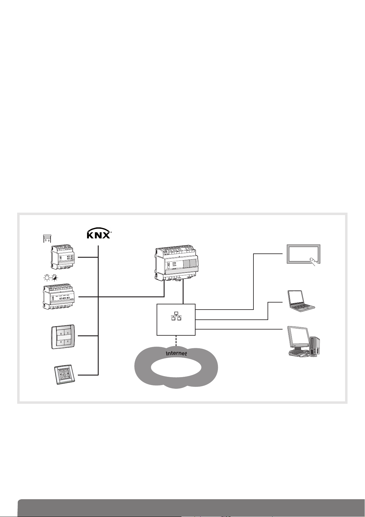
1.2 General scheme of domovea System
domovea consists in 3 different modules:
• The Server:
Hardware: TJA450, in this case, the server is connected to KNX and to IP.
• The Client: the client is a software module delivered together with the server on a USB stick.
This software is the customer’s interface and has to be installed on a computer, on a touch panel or
on Media Center. Up to 30 Clients may be installed behind a Server
.
• The Configurator: the configurator is a software module also delivered together with the server hardware
on a USB stick. This software is a tool to design and program the customer’s interface. It can be installed
on the installer’s laptop.
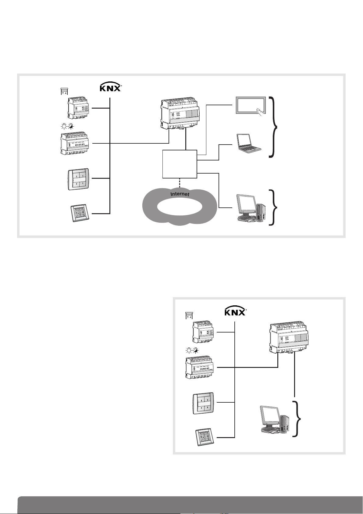
The following pictur
es show the complete Tebis – domovea architecture.
domovea uses 2 different networks inside a building:
• KNX network (wired, radio or mixed) where all the KNX sensors, actuators, touch panels etc. are installed.
• Ethernet network where all the IP devices are connected to the LAN (Local Area Network): PC, touch
panels, cameras etc.
The domovea server TJA450 realises the gateway between the two networks.
The remote domovea access is given over a portal: www.domovea.com
domovea client
LAN
Router/Switch
www.domovea.com
5
1.3 Required configuration
The server domovea TJA450 shall be installed in the electrical panel.
The Client and the Configuration tool softwares can be installed
on any device with operating systems such as Microsoft Windows
XP, WIndows VISTA and Windows 7.
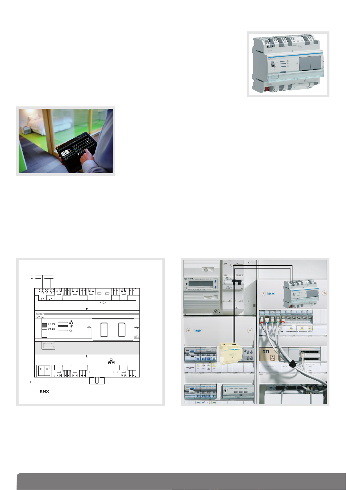
1.4 Hardware installation: server TJA450
The server should be installed in the VDI distribution panel.
1.4.1. Connexion diagramm
N.B.: if there is no VDI distribution panel, the server can be installed in the usual electrical board.
In this case, the ELV and SELV connections must be secured in an appropriate way.
TG200
TJA450
24V DC
3
30V DC
+
-
Bus
LAN
6
1.4.2 Network connexions
Installation behind a DHCP Server
The TJA4X0 is connected to a DHCP server (router or any other device having a DHCP function).
In this case, the server TJA450 automatically waits for an IP address coming from the DHCP (Dynamic Host Configuration Protocol) server.
Installation without DHCP Server
If there’s no DHCP the domovea server waits for 40 seconds and after this time, the server takes the
following default: IP address: 192.168.0.253 with following
Subnet mask: 255.255.255.
!
It’s possible to connect the server directly to
the installer’s PC where the configuration tool
is installed. In this case, after 40 seconds, the
domovea server takes following:
IP address: 192.168.0.253
Subnet mask: 255.255.255.0
The computer shall be addressed as follows:
IP address: 192.168.0.xxx
(with xxx between 2 and 252)
Subnet mask: 255.255.255.0
NB:
If a firewall is active on the local network, the
traffic from clients to the server domovea must
be authorized.
Domovea server uses ports TCP 4504 and
UDP 3702 in reception. The firewall must be
configured to allow incoming traffic through
these ports.
r
r
domovea
client
LAN
DHCP
server
www.domovea.com
domovea
configurato
LAN
domovea
configurato
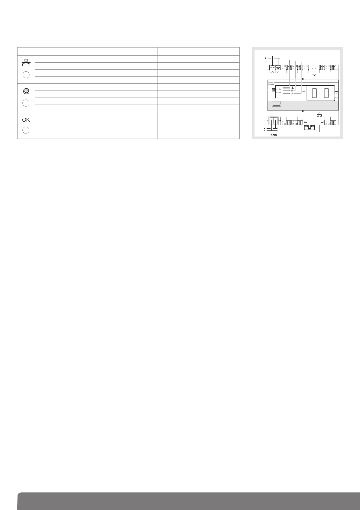
1.4.3 TJA4X0 Front Panel
The following table summarizes the meaning of each LED (, and ):
LED State Description Failure correction
Off Disconnected network cable Connect the network cable
Fixed Red Conflict of IP address Check IP addresses used on the server
Green flickering Standby waiting for DHCP Server IP address /
1
Fixed Green Address IP Received /
Off No connection to the portal /
Fixed Red Portal unavailable or connection denied Check your Internet connection
Green flickering Connecting to desired portal /
2
Fixed Green Connection to desired portal successful /
Red flickering Power supply problem Check power supply
Fixed Red Defective product Contact Hager Support Department
Green flickering Domovea Server starting /
3
Fixed Green Domovea Server running /
24V DC
햴
3
30V DC
+
-
Bus
LAN
The switch has two different positions:
Online: - The server is set to DHCP configuration (default factory setting): at connection, the server
is put in standby for 40s, expecting an IP address from a DHCP server. If no IP address is
assigned when the standby ends, the server is connected to the default IP address
(192.168.0.253).
- If the server is configured in fixed IP address, it will connect immediately to the IP address
it was assigned to. In this case, no connection to the default address will occur.
- The IP network is connected
- domovea portal is connected
- Bus KNX is connected
Offline: - In any server configuration (fixed IP or DHCP), the server will expect an IP address from the
DHCP server at connection. After 40s standby, if no IP address were assigned, the server is
connected to the default IP address (192.168.0.253).
- The IP network is connected
- domovea portal is disconnected
- Bus KNX is disconnected.
Recommendations:
In general, switch 4 shall always be in on-line position.
Switch to off-line mode only in the following cases:
- If you want to be able to disconnect from the portal and KNX network
- Loss of IP address of the server in fixed IP configuration: in this case, the off-line mode will en-
able you to read or reconfigure the server IP address using domovea configuration software
TJA450 has 3 USB connectors: 2 on front panel behind the rubber covers and 1 on top. These USB
connectors are used for updating server software.
Server software updating:
Create a directory named "autorun" (2) on a USB Memory Stick (1) and copy the update file with .cab
extension (3) at the root. Next, plug this stick in one of TJA450's USB ports. LED 3 will flicker for about
1 minute, and then go off. The server will reset and start with the new software version loaded.
7
8
1.5 Installation of client software
Installing the client software and configuration tool is possible on computer terminals running on operating
systems Windows XP, Windows Vista and Windows 7, 32 or 64 bits.
• For installing software, insert the USB stick provided with the TJA450 server in a USB port of
the target terminal.
• Double-click the My Computer icon on the Desktop, then double-click the domovea icon in
the list of connected devices.
In the list displayed on the scr
een, select the installation language and the 32 or 64 bit Windows
version.
domovea requires Microsoft.NET Framework 3.5 SP1 to run. Install softwar
e as needed.
Note: In order to detect your Windows version (32 or 64 bits) proceed as follows:
• Click the Windows + pause buttons.
• Click the General tab, the operating system will display as follows:
- 64 bit operating system: x64 will be printed after the name of the operating system
- 32 bit operating system: no indication appears after the name of the operating system
1.6 Connect the computer terminal to the server
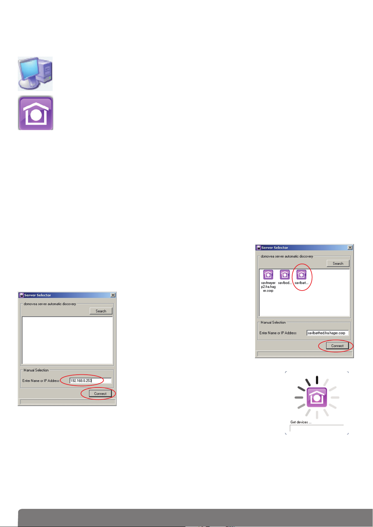
1.6.1 Behind a router or any other DHCP server
• Start the configuration tool. The domovea configuration tool looks
for all existing servers present on the connected Ethernet network.If a DHCP server is present, it will give an IP address to the domovea server and an automatic discovery procedure will find the
device (1).
• Select the desired domovea server and click Connect (2).
If the domovea server is not automatically detected, it’
s possible to
type the IP address of the server (3)
to get connection and click
Connect (
4).
• The initialization icon appears.
The configuration tool is r
eady to be used.
1
3
4
2
9
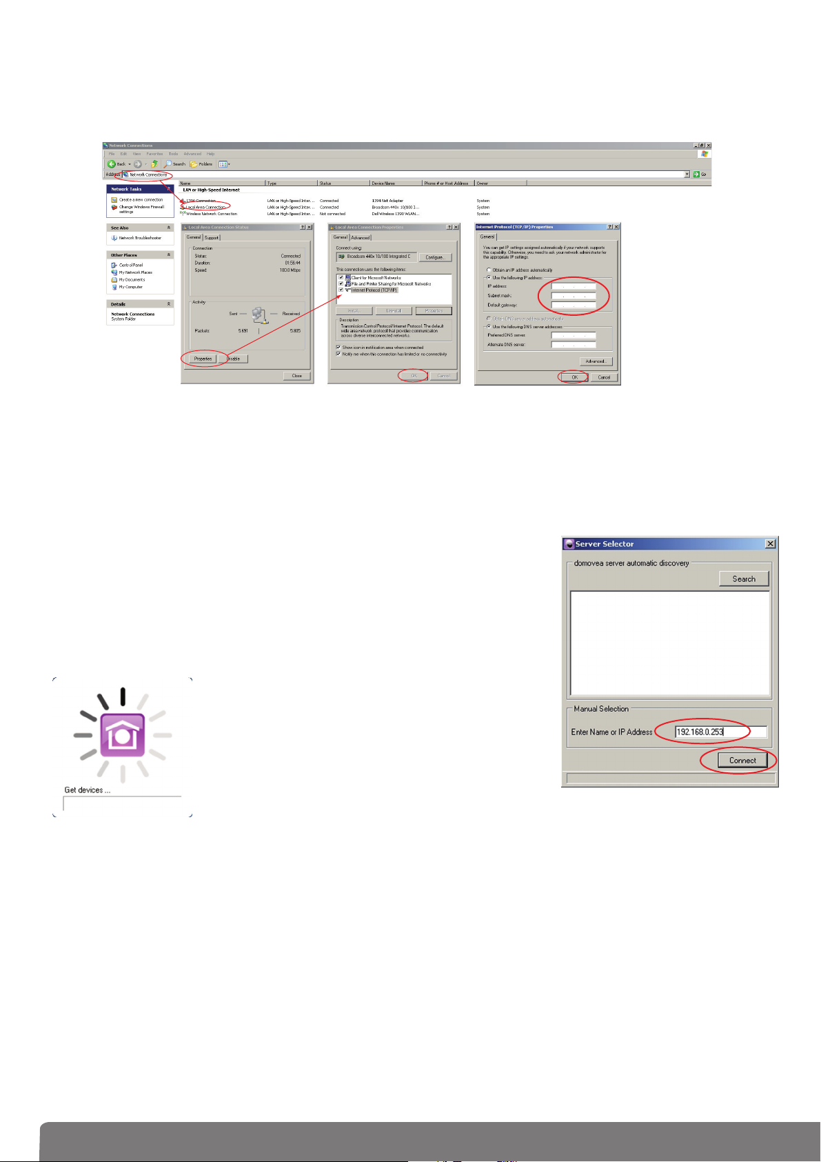
1.6.2 Connection without DHCP server
• Change the IP address on the computer terminal to put it on the same network (steps 1 through 7):
Once, both devices are on the same net, you can work normally and proceed with next step.
• Start the configuration tool and type the IP address of the server (8)
to get connection and click Connect (9).
• The initialization icon appears.
The configuration tool is r
eady to be used.
1
2
3
4
5
7
6
8
9
10
2. Configuration tool description
2.1 General menu
Server selection: this function is used to select the server. The selection is done
automatically when launching the configuration tool but it is
possible to select another one fr
om here.
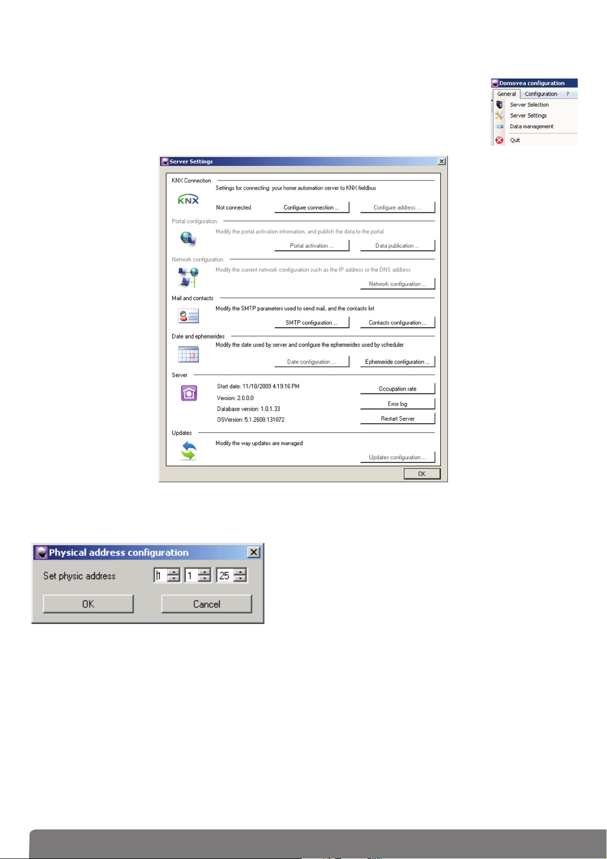
Server settings: this function is used to set the servers settings.
KNX interface: to configur
e the KNX connection.
Configure the address: Used to configure the physical
addr
ess of KNX interface.
Default value: 15.15.254
OK: to validate
Cancel: to cancel the data entry
Portal configuration: to configure the domovea portal settings (See information note "Portal remote access
configuration").
Network configuration: Used to configure the network parameters. This configuration is only required if the
server is not connected to a DHCP server. It allows to set a fixed IP address different from the defaut IP
address (192.168.0.253) to be set manually. If you select this option, you must specify an IP address, a subnetwork mask, the default gateway and the server DNS in the appropriate fields.
 Loading...