

Page 1
6LE005270A
TYA670W
q
z
i
6LL003327A
Area
Line
Ptcp.
Nb.
KNX-DALI-Gateway
tunable white
KNX-DALI-Gateway
wit moduleerbaar
• Electrical equipment must be installed
and fitted by qualified electricians only.
• Failure to observe the instructions may
cause damage to the device and result
in fire or other hazards
• This device is not suitable for
disconnection of the mains power
supply.
• L'appareil ne convient pas pour la
déconnexion de l'alimentation du
réseau.
• The DALI control voltage is a functional
extra-low voltage (FELV). D u r i n g
the installation, ensure there is a safe
separation between KNX and DALI.
TYA670W
Product description
The DALI TYA670W KNX gateway is used to interface
DALI lighting applications with the KNX system.
Function
System information
This device is a product of the KNX system and
complies with the KNX directives. Detailed technical
knowledge obtained in KNX training courses is a
prerequisite to proper undertsanding… The function
of this device depends upon the software. Detailed
information on loadable software and attainable
functionality as well as the software itself can be
obtained from the manufacturer's product
dartabase.
Planning, installation and commissioning of the
device are carried out with the aid of KNX-certified
software. Full functionality with KNX commissioning
software version ETS3.0f onwards.
An updated version of the product database,
technical descriptions and conversion programs
and other auxiliary programs are availbale on our
internet website.
Product characteristics
• Controls up to 64 DALI products in up to 32
groups
• Individual control, group control or general control
• Setting the color temperature for luminaires with
DALI operating device Type 8 for Tunable White in
accordance with IEC 62386-209
• 16 scenes
• Eect control for dynamic sequences and sets of
colours
• Reading of the status of DALI products via KNX,
e.g. light intensity, light fitting fault, etc.
• Manual control of DALI groups
• Priority
• Feedback on the status of switching and the
value of light intensity in bus mode and manual
mode
• General status feedback
• General command function
• Emergency lighting function
• Inhibition function for each group
• Separate switching and tripping delay
• Timer function with cut-o pre-warning
• Movement function : in combination with a
presence detector, reduction of the light intensity
when no movement is detected before turning o
• Online or oine commissioning of DALI products
with ETS plug-ins
• Surge protection and overload protection
• Possibility to replace an individual DALI product
without software during service
• Operating hours counter
• Delivery status : job-site mode, possibility of
ordering DALI groups using the keyboard. All
DALI products are ordered jointly.
• Signal of the global switching status of the DALI
devices, e.g. to switch o the mains voltage of
the DALI devices to avoid stanby losses.
:.?nB
DALI
Description
Da-
Da+
TYA670W
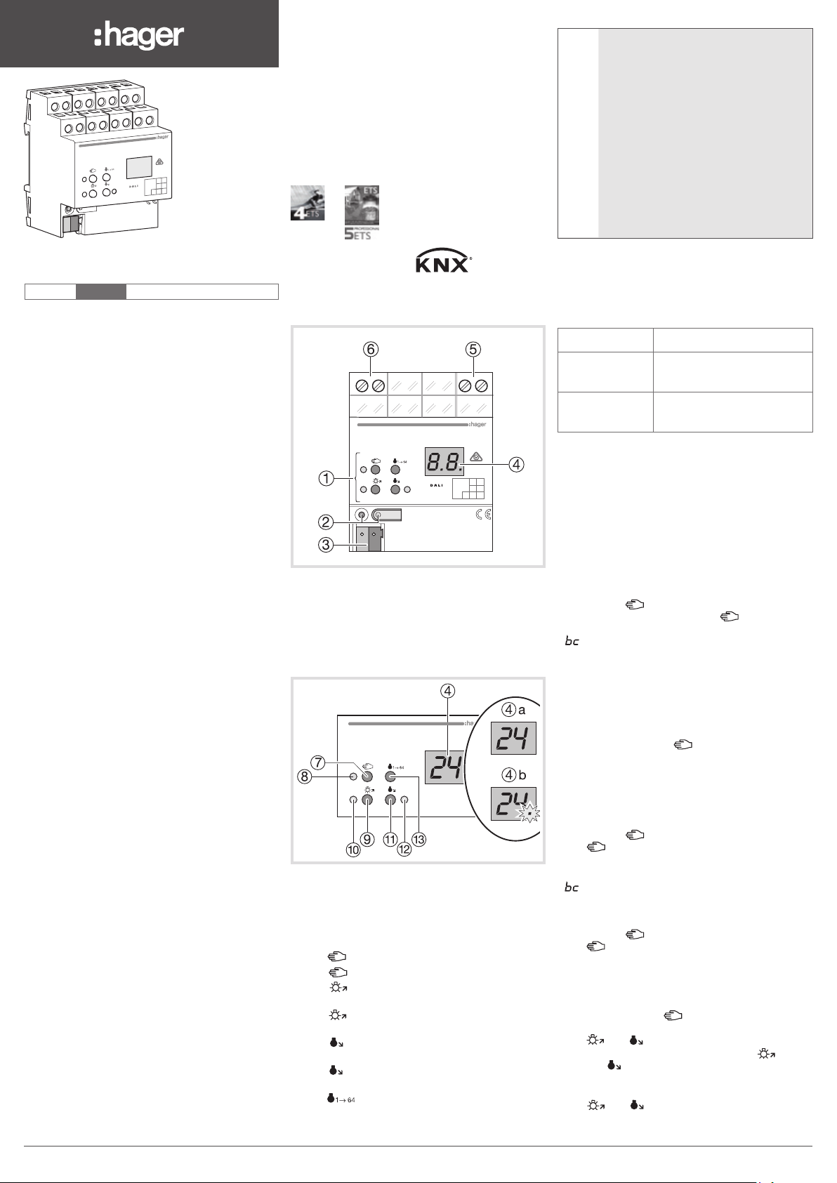
1 Keyboard for manual control
2 Push Button and LED indicator for addressing
3 KNX Connection
4 Display of DALI numbers
5 Connection to the network
6 DALI connection.
L
N
Area
Line
Ptcp.
Nb.
Operating mode
Control Elements
TYA670W
4 Display of the DALI numbers
- 4
a
DALI Groups (1...32)
- 4
b
Individual participants (1...64)
- bc : If the display shows bc (broadcast
operation), the device is not programmed or set
to master control in the KNX configuration. All
DALI devices are then controlled jointly.
7 Key
8 LED
9
A LED on : Individual participant or DALI group
Z
E LED on : Individual participant or DALI group
R
: manual control
on : Manual mode permanently enabled
Key : Turn on or adjust the light intensity
brighter
enabled : light intensity 1…100%
Key : Turn o or adjust the light intensity
darker
disabled: light intensity 0%
Key
: Turn o all DALI participants.
Operating mode
Bus mode controls via push button
Short-term
manual mode
Permanent
manual mode
- In manual mode, a bus mode is not possible.
H
- In the event of a failure of the bus, manual
control is possible.
- After the bus failure and a return to service, the
device operates in bus mode.
- After a power cut and a return to service, the
gateway operates in bus mode.
- Manual mode is disabled by a telegram in current
mode.
Enabling short-term manual mode
The operation of the keyboard is programmed and
is not locked.
- Press the
displayed on the screen, the
o or
is displayed on the screen (refer to bc). In this
mode, individual control of the participants is not
possible.
Disabling short-term manual mode
The gateway is in short-term manual mode.
- No manipulation for 5 seconds
or
- Short press on the
the gateway exits short-term manual mode. The
display turns o.
Enabling permanent manual mode
The operation of the keyboard is programmed and
is not locked.
- Press the
The
LED is lit, 01 is displayed on the screen,
permanent manual mode is enabled.
or
is displayed on the screen (refer to bc).
-
Disabling permanent manual mode
- Press the
The
LED turns o and bus mode is enabled.
Controlling the DALI participants
The gateway is in permanent or short-term manual
mode.
Press briefly on the key ( < 1 second) until the
-
number of t he desired DALI pa rticipant i s displayed
The and LEDs display the status.
- Control the DALI participant with the key or
with the
Long press : varies the light intensity brighter/
darker
and LEDS display the status.
The
- In permanent manual mode, after having
been through all the available DALI participant
manual control using the
keyboard, automatic return to
bus mode
manual control exclusively via
the gateway
key briefly (<1 second). 01 is
LED remains
key (<1 second) until
key for at least 5 seconds.
key for at least 5 seconds.
key Short press : turns on and o
1
6LE005270A
Page 2
numbers, the gateway exits manual mode after an
A
A
A
additional press.
Turning o all the DALI participants
The gateway is in permanent manual mode.
- Press the
key.
All DALI participants are switched o.
Locking the DALI participants or groups
individually
The gateway is in permanent manual mode.
- Press briefly on the
key ( < 1 second) until the
desired DALI number is displayed.
The
and LEDs display the status.
- Press the
and keys simultaneously for at
least 5 seconds.
The DALI number selected flashes on the display
screen.
The DALI participant or group is locked.
- Enable bus mode (leaving permanent manual
mode).
A locked DALI participant can be controlled in
manual mode.
Unlocking the DALI participants or groups
individually
The gateway is in permanent manual mode
- Press briefly on the key
(<1 second) until the
desired DALI number is displayed.
- Press the
and keys simultaneously for at
least 5 seconds.
The DALI participant or group is released.
The display on the screen no longer flashes.
- Enable bus mode (leaving permanent manual
mode).
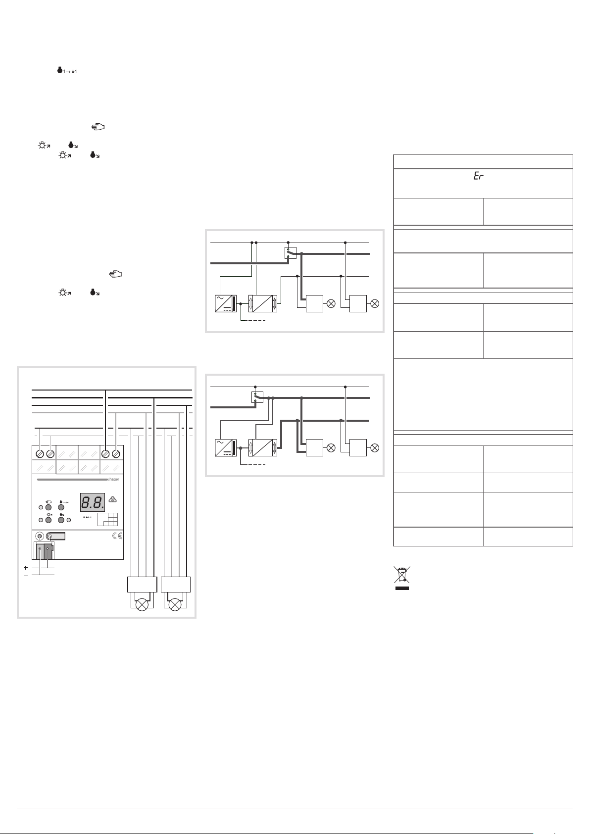
Connection
Bus 30 V
230 V 50/60 Hz
Area
Line
Ptcp.
Nb.
da da N L da da N L
L1
L2
L3
da+
da -
N
TYA670W
Electrical connection
Connect the device according to the diagram above.
Observe the temperature range. Ensure adequate
cooling.
When performing installation, perform the
installation in such a way that when the area is
disconnected the lines carrying both the DALI and
also the mains voltage are disconnected.
If multiple circuit breakers supply dangerous
voltages to the device or load, couple the miniature
circuit breakers or label them with a warning, to
ensure disconnection is guaranteed.
DALI devices from some manufacturers have
expanded functions and can be controlled. In the
case of upgrades of existing DALI installations,
remove all the corresponding control devices.
The DALI control voltage is a functional extra-low
voltage (FELV).
Operation of the emergency lighting
The device can be used in centrally-powered
emergency lighting systems.
The statutory and standard specifications vary
G
from country to country. In any event, the user /
technical planner should check whether the specific
specifications should be maintained.
Observe the number of DALI devices in the
G
emergency luminaires used.
Emergency lighting systems with a central safety
supply are required in buildings larger than 2000 m².
Depending on the scope of functions of the system,
only the emergency luminaires are supplied by the
central safety supply (figure 1), or the KNX system and
DALI gateway are also supplied (figure 2). In the latter
case, in emergency operation, the DALI gateway can
transmit the appropriate fault messages to a central
system and other DALI gateways in the system.
Figure 1 : Emergency lighting supplied by the
central emergency power supply
AC 230 V
C/DC 230 V
DALI
KNX
KNX
DALI
L, N
da
L, N
da
Figure 2 : Emergency lighting, KNX supply and
the DALI gateway are supplied by the central
emergency power supply circuit.
C 230 V
C/DC 230 V
DALI
*
*The KNX power supply must be adapted to the
voltage of the AC / DC safety source.
KNX
KNX
DALI
L, N
da
L, N
da
Commissioning
Downloading the physical address and the
application software
- Supply power to the product from the mains
- Connect the KNX bus
- Download the physical address
- Commission DALI system using commissioning
software
- Download the application software into the device
Programming is not possible if the product is not
powered via the mains.
Technical data
Supply
Rated voltage 110 ... 240 V v
Mains frequency 50 / 60 Hz
Rated voltage DC 110 ... 240 V s
Power loss max. 3 W
Ambient conditions
Operating tempertaure -5 ... +45 °C
Storage /transport temperature -25 ... +70 °C
DALI
Rated voltage DALI 16 V (typ.)
Number of DALI subscribers max. 64
DALI transmission rate 1,2 kbit/s
DALI protocol EN 62386
Cable type Sheated cable 230 V,
e.g. NYM
DALI cable lenght
with Ø 1,5 mm² max. 300 m
with Ø 1,0 mm² max. 238 m
with Ø 0,75 mm² max. 174 m
with Ø 0,5 mm² max. 116 m
Housing
Fitting width 72 mm / 4 modules
Connection of power supply and DALI
Connection mode Screw terminal
single stranded 0,5 ... 4 mm²
Finely strande without conductor sleeve 0,5 ... 4 mm²
Finely strande with conductor sleeve 0,5 ... 2,5 mm²
KNX
KNX Medium TP
Commissionning mode S Mode
Rated voltage KNX DC 21 ... 32 V SELV
Power consumption KNX typ. 150 mW
Connection type for bus KNX Terminal
This manual is an integral part of the product
and must be kept by the end user.
What to do if…
The screen displays , the connected DALI
devices have no functions, no control is
possible
Cause : network
voltage on the DALI
bus
The screen displays bc in manual mode,
control of some light fittings is not possible.
Cause : the device has
not been programmed
or is programmed to
"Broadcast"
Individual DALI devices have no function
Cause 1 : Load is
defective, e.g. lamp
Cause 2 : DALI device
is defective
Press buttons 7 and 13 together for at least 10
seconds.
The device detects the exchanges DALI device
and loads in the necessary data. The display
LE
shows
.
Simultaneous exchange of multiple DALI
G
devices is only possible with commissioning
software and project data.
None of the DALI groups can be operated
Cause 1 : All DALI
groups disabled via bus
or manual operation
Cause 2 : Continuous
manual mode switched on
Cause 3 : Application
software has been
stopped, programming
LED is flashing
Cause 4 : Application
software missing or faulty
Correct Disposal of This product
(Waste Electrical & Electronic Equipment).
(Applicable in the European Union and other European
countries with separate collection systems).
This marking shown on the product or its literature indicates that
it should not be disposed with other household waste at the end
of its working life. To prevent possible harm to the environment or
human health from uncontrolled waste disposal,
please separate this from other types of waste and recycle it responsibly to promote the sustainable reuse of material resources.
Household users should contact either the retailer where they
purchased this product, or their local government oce, for details
of where and how they can take this item for environmentally safe
recycling.
Business users should contact their supplier and check the terms
and conditions of the purchase contract. This product should not
be mixed with other commercial waste for disposal.
Usable in all Europe M and in Switzerland
Solution : correct the
installation wiring fault
Solution :
program the
gateway, commission
the DALI system
Solution : Exchange
load
Solution : Exchange
defective device and
switch on voltage
Solution : Cancel
disabling
Solution : Deactivating
permanent manual control
Solution : Perform reset:
Disconnect device from
bus, switch on again
after approx. 5 seconds
Solution : Check
programming and correct
2 6LE005270A
Page 3

i
z
TYA670W
6LL003327A
Area
Line
Ptcp.
Nb.
6LE005270A
TYA670W
Presentatie van het product
Met de gateway KNX-DALI TYA670W is interface
mogelijk tussen de DALI verlichtingstoepassingen
en het KNX systeem.
Werking
Systeeminformatie
Dit apparaat is een product van het KNX-systeem en
voldoet aan de KNX-richtlijnen. Het is noodzakelijk
over gedetailleerde kennis te beschikking die kan
worden verworden door de KNX-opleidingen te
volgens.
De werking van het apparaat is afhankelijk van de
software. De gedetailleerde informatie betreende
de softwareversies en de werking, evenals de
software zelf, is aangegeven in de database van de
fabrikant.
De programmering, installatie en indienststelling
van de apparatuur gebeurt met de hulp van een
door KNX gehomologeerde software. De talrijke
functionaliteiten worden verzekerd vanaf versie
ETS3.0f van de software voor de inbedrijfstelling
van KNX.
De huidige versies van de database van de
producten, de technische beschrijvingen,
de conversieprogramma’s evenals andere
hulpprogramma’s zijn op elk ogenblik beschikbaar
op onze internetsite.
Productkenmerken
• Bediening van max. 64 DALI producten in max.
32 groepen.
• Individuele bediening, groepsbediening of
algemene bediening
• 16 scènes
• Eectcontrole voor de dynamische sequenties en
kleurensets
• Aflezen van de staat van de DALI producten via
KNX, bijv. de lichtsterkte, defecte lamp…
• Handbediening van de DALI groepen
• Prioriteit
• Informatie feedback betreende de
omschakelingstoestand en de waarde van de
lichtsterkte in de handbedieninsmodus.
• Terugkeer naar algemene toestand
• Functie algemene bediening
• Functie noodverlichting
• Uitsluitingsfunctie voor iedere groep
• Aparte inschakel- en uitschakelvertraging
• Tijdklokfunctie met waarschuwing vóór het doven
• Circulatiefunctie : in combinatie met een
bewegingsmelder, vermindering van de
lichtsterkte wanneer er vóór het doven geen
enkele beweging gedetecteerd is
• Online of oine ingebruikname van de DALI
producten met ETS plugin
• Bescherming tegen overbelasting
• Overspanningszekering
• Vervanging mogelijk van een individueel DALI
product zonder software tijdens de service
• Teller bedrijfsuren
• Leveringstoestand: werkplaatsmodus, bediening
van de DALI groepen mogelijk d.m.v. het
toetsenbord. Alle DALI producten worden
gezamenlijk bediend.
KNX-DALI-Gateway
wit moduleerbaar
KNX-DALI-Gateway
tunable white
:.?nB
Beschrijving
Da-
Da+
TYA670W
1 Toetsenbord voor handbediening
2 Drukknop en controlelampje adressering
3 KNX-verbinding
4 Display met de Dali nummers
5 Verbinding met het netwerk
6 Verbinding Dali
Bediening
Bedieningselementen
TYA670W
4 Displays van de DALI nummers
4a DALI groepen (1...32)
4b Individuele deelnemers (1...64)
Als de weergave bc (broadcastcommando)
aangeeft, wordt het apparaat niet
geprogrammeerd of de KNX-configuratie wordt
geregeld via de algemene bediening, terwijl alle
deelnemers samen zullen worden bediend.
7 Toets
8 LED
permanent geactiveerd
9 Toets
meer licht
A LED
groep DALI geactiveerd : lichtsterkte 1…100%
Z Toets
minder licht
: handbediening
brandt : Handbedieningsmodus
: Lichtsterkte inschakelen of variëren
brandt : Individuele deelnemer of
: Lichtsterkte uitschakelen of variëren
DALI
L
N
Area
Line
Ptcp.
Nb.
• Inbouw en montage van elektrische
q
apparaten mogen uitsluitend
geschieden door een landelijk erkend
installatiebedrijf.
• LBij veronachtzaming van de
installatie-instructies kunnen schade
aan het toestel, brand of andere
gevaren optreden.
• Risico op elektrocutie: koppel altijd de
netstroom los voordat u tussenkomt
op het apparaat of de lading. Koppel
vooral alle vermogenschakelaars die
gevaarlijke spanning aan het apparaat
of de lading leveren, los. .
• De DALI bedieningsspanning is een
zeer lage functionele spanning ZLFS.
Zorg er tijdens de installatie voor dat er
een veilige scheiding tussen KNX en
DALI is.
E LED
brandt : Individuele deelnemer of
groep DALI gedeactiveerd, lichtsterkte 0%
R Toets
: deelnemers uitschakelen.
Busmodus cbediening via drukknop
Korte handbe-
dieningsmodus
plaatselijke
handbediening d.m.v.
het toetsenbord,
automatische terugkeer
naar de busmodus
Permanente hand
bedie-ningsmodus
handbedieningsmodus
uitsluitend op de gateway
Werking
- In de handbediening is een busmodus niet
H
mogelijk.
- In geval van een defecte bus is handbediening
mogelijk.
- Na een defect van de bus en nieuwe inschakeling
werkt het apparaat in de busmodus.
- Na een stroomonderbreking en nieuwe
inschakeling werkt de gateway in de busmodus.
- De handbedieningsmodus wordt gedeactiveerd
d.m.v. een telegram in de lopende modus.
De korte handbedieningsmodus activeren
De werking van het toetsenbord is geprogrammeerd
en is niet vergrendeld.
- Druk kort op de toets
weergegeven op het scherm, de LED
oder Als de weergave bc (Zie bc hierboven). In
deze modus is individuele bediening van de
deelnemer niet mogelijk.
De korte handbedieningsmodus deactiveren
- Geen handelingen gedurende 5 seconden
of
- Korte druk op de toets
korte handbedieningsmodus verlaat. De display
gaat uit.
De permanente handbedieningsmodus
activeren
- Houd de toets
ingedrukt. De LED
weergegeven op het scherm, de permanente
handbedieningsmodus is geactiveerd.
of
- bc wordt weergegeven op het scherm : (Zie bc
hierboven)
De permanente handbedieningsmodus
deactiveren
- Houd de toets
ingedrukt. .
De LED
dooft, de busmodus is geactiveerd.
De DALI deelnemers bedienen
De gateway is in permanente handmatige modus
of van korte duur.
Druk kort op de toets
de gewenste DALI deelnemer wordt weergegeven
De LED’s
en
- Bedien de DALI deelnemer met de toets
met de toets
.
Korte druk : in- en uitschakelen
Lange druk : lichtsterkte variëren. meer licht /
kurz, < 1 s, 01 wordt
blijft uit of.
totdat de gateway de
minstens 5 seconden
brandt, 01, wordt
minstens 5 seconden
totdat het nummer van
geven de toestand weer
.
of
6LE005270A3
Page 4

minder licht
A
A
A
De LED’s
en geven de toestand weer.
In de permanente handbedieningsmodus, na alle
nummers van de beschikbare DALI deelnemers
te hebben nagelopen, verlaat de gateway de
handbedieningsmodus na nogmaals gedrukt te
hebben.
Alle DALI deelnemers uitschakelen
De gateway staat in de permanente
handbedieningsmodus.
- Druk op de toets
Alle DALI deelnemers zijn uit.
De deelnemers of groepen DALI afzonderlijk
vergrendelen
De gateway staat in de permanente
handbedieningsmodus.
- Druk kort op de toets
< 1 s, totdat het
gewenste DALI nummer wordt weergegeven. De
LED’s
- Druk de toetsen
en geven de toestand weer.
en minstens 5 seconden
lang gelijktijdig in.
Het geselecteerde DALI nummer knippert op het
weergavescherm.
De deelnemer of de groep DALI is vergrendeld.
- Activeer de busmodus (verlaat de permanente
handbedieningsmodus).
Een vergrendelde DALI deelnemer kan in de
handbedieningsmodus bediend worden.
De deelnemers of groepen DALI afzonderlijk
ontgrendelen
De gateway staat in de permanente
handbedieningsmodus.
- Druk kort op de toets
(< 1 s) totdat het
gewenste DALI nummer wordt weergegeven.
- Druk de toetsen
en minstens 5 seconden
lang gelijktijdig in.
De deelnemer of groep DALI is vrij.
De weergave op het scherm knippert niet meer.
- Activeer de busmodus (verlaat de permanente
handbedieningsmodus).
Aansluiting
Bus 30 V
230 V 50/60 Hz
Area
Line
Ptcp.
Nb.
da da N L da da N L
L1
L2
L3
da+
da -
N
TYA670W
Elektrische aansluiting
Sluit het apparaat aan volgens het bovenstaande
schema. Houd rekening met het temperatuurbereik.
Zorg voor voldoende koeling.
Voer de installatie zo uit, dat de Dali spanningsen voedingskabels worden losgekoppeld in het
geval een domein moet worden ontgrendeld. DALITeilnehmer einiger.
De spanning van de DALI-bediening is een zeer
lage functionele spanning (ZLFS).
De DALI-apparaten van bepaalde fabrikanten
hebben verbrede functies en kunnen worden
bediend. Als bestaande DALI-installaties worden
verbeterd, verwijdert u alle overeenkomende
bedieningsmiddelen.
Funktionsweise der Notfallbeleuchtung
De gateway kan worden gebruikt in de
noodverlichtingssystemen met gecentraliseerde
voeding.
De wettelijke voorschriften en de normalisatie
G
verschillen afhankelijk van het land. De gebruiker/
planner moet in alle gevallen controleren of de
technische voorschriften worden nageleefd.
Houd rekening met het aantal DALI-deelnemers
G
in de gebruikte noodverlichtingen.
In gebouwen met een oppervlakte van meer dan
2000m², zijn noodverlichtingsinstallaties met een
gecentraliseerde noodvoeding nodig. Afhankelijk
van de werking van de installatie, krijgen alleen
de noodverlichtingen stroom van de noodvoeding
(afbeelding 1) of de KNX-installatie en de DALIgateway (afbeelding 2). In dit laatste geval kan de
DALI-gateway in de noodmodus defectberichten
sturen naar een centrale of een extra DALI-gateway
in de installatie.
Afbeelding 1 : Noodverlichting gevoed door het
centrale veiligheidsvoedingscircuit
AC 230 V
C/DC 230 V
DALI
KNX
KNX
DALI
L, N
da
L, N
da
Afbeelding 2 : Noodverlichting, KNX voeding
en DALI Gateway gevoed door het centrale
veiligheidsvoedingscircuit.
C 230 V
C/DC 230 V
DALI
*
KNX
KNX
DALI
L, N
da
L, N
da
* De KNX-voeding moet worden aangepast aan de
spanning van de AC/DC-beveiligingsbron
Inbedrijfstelling
Het fysieke adres en de toepassingssoftware
downloaden
- Voorzie het product van voeding via het
spanningsnet.
- Sluit de KNX bus aan.
- Download het fysieke adres.
- DALI-systeem van de Commissie met
inbedrijfstellingssoftware.
- Download de applicatiesoftware in het apparaat.
Programmering is niet mogelijk als het product niet
door het spanningsnet van voeding voorzien wordt.
Technische gegevens
Voeding
Nominale spanning
Netfrekvens
Nominel DC spænding 110 ... 240 V s
Eekttab : max. 3 W
Omgivende betingelser
Driftstemperatur 5 °C … +45 °C
Temperatur for opbevaring -25 °C … +70 °C
DALI
Nominel DALI-spænding 16 V (typ.)
Antal DALI-deltagere max. 64
DALI-overførselsrate 1,2 kbit / s
DALI-protokol EN 62386
110 / 240 V v
50 / 60 Hz
Kabeltype : 230 V afskærmet ledning, f.eks. NYM
Kabellængde til DALI 1,5mm² max. 300 m
for Ø xx mm² 1,0mm² max. 238 m
for Ø xx mm² 0,75mm² max. 174 m
for Ø xx mm² 0,5 mm² max. 116 m
Boks
Integrationsbredde 72 mm (4 Module)
Tilslutning til strømforsyning og DALI
Tilslutningstype Skrueklemme
Enkelttrådsledning 0.5 … 4 mm²
med tynde ledninger uden endestykke
0.5 … 4 mm²
med tynde ledninger med endestykke
0.5 … 2,5 mm²
KNX KNX
Medium KNX TP
Tilstand for idriftsætning S Mode
Nominel KNX-spænding DC 21 ... 32 V SELV
Absorberet eekt til KNX typ. 150 mW
Bussens tilslutningstype KNX-aansluitklem
Wat de toen als…
Het beeldscherm ER weergeeft, de
aangesloten DALI apparaten niet werken,
bediening niet mogelijk is
Oorzaak : netspanning
op de DALI bus
Het beeldscherm geeft bc weer in de
handbedieningsmodus, sommige lampen
kunnen niet bediend worden
Oorzaak : de
gateway is niet
geprogrammeerd.
Individuele DALI-deelnemer buiten werking
Oorzaak 1: er is een
lading defect (bijv.: een
lamp).
Oorzaak 2: het DALIproduct is defect.
Druk gedurende minstens 10 seconden
tegelijkertijd op de toetsen 7 en 13.
De DALI-gateway herkent het vervangen
DALI-apparaat en laadt de nodige gegevens.
"LE" wordt weergegeven op het scherm.
! Het simultaan vervangen van meerdere DALI-
G
deelnemers is alleen mogelijk met de software
voor de inbedrijfstelling en de gegevens van
het project.
Er kunnen geen DALI-groepen worden bediend
Oorzaak 1 : alle
DALI-groepen zijn
vergrendeld via de
bus of de handmatige
bediening.
Oorzaak 2 :
de permanente
handmatige modus is
geactiveerd
Oorzaak 3 : de
toepassingssoftware
is gestopt, de
programmerings-LED
knippert.
Oorzaak 4 : de
toepassingssoftware
ontbreekt of is fout.
Correcte verwijdering van dit product (elektrische &
elektronische afvalapparatuur).
Dit merkteken op het product of het bijbehorende informatiemateriaal
duidt erop dat het niet met ander huishoudelijk afval verwijderd moet
worden aan het einde van zijn gebruiksduur. Om mogelijke schade
aan het milieu of de menselijke gezondheid door ongecontroleerde
afvalverwijdering te voorkomen, moet u dit product van andere soor
ten afval scheiden en op een verantwoorde manier recyclen, zodat
het duurzame hergebruik van materiaalbronnen wordt bevorderd.
Huishoudelijke gebruikers moeten contact opnemen met de winkel
waar ze dit product hebben gekocht of met de gemeente waar ze
wonen om te vernemen waar en hoe ze dit product milieuvriendelijk
kunnen laten recyclen.
Zakelijke gebruikers moeten contact opnemen met hun leverancier
en de algemene voorwaarden van de koopovereenkomsten nalezen.
Dit product moet niet worden gemengd met ander bedrijfsaval voor
verwijdering.
Te gebruiken in heel Europa å en in Zwitzerland
Oplossing :
de
verkeerde bekabeling
van de installatie
corrigeren
Oplossing : de gateway
programmeren,
het DALI systeem
inschakelen
Oplossing: de lading
vervangen
Oplossing
.
: Dhet
defecte product
vervangen en voeding
inschakelen.
Oplossing : de
vergrendeling
verwijderen
Oplossing :
permanente
deactivering van de
handmatige modus
.
Oplossing : een
herinitialisatie
uitvoeren: het apparaat
loskoppelen van de
bus, opnieuw aansluiten
na ca. 5 seconden
.
Oplossing : de
programmering
controleren en
corrigeren
Hager 06.18 - 6LE005270AHager Controls S.A.S., 33 rue Saint-Nicolas, B.P. 10140, 67703 SAVERNE CEDEX, France - www.hager.com4
.
-
 Loading...