

Page 1
BODYMOUNT
DESCRIPTION
SPECIFICATION
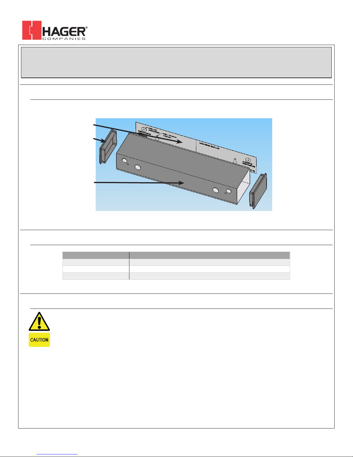
DIMENSIONS
12.25” x 3.00” x 2.00” (313mm x 76mm x 51mm)
WEIGHT
1.4 lbs (0.64 kg)
MATERIAL
Black painted aluminum and vinyl
EXTRUSION
MOUNTING TEMPLATE
END CAP (2)
DEVICES COVERED IN THIS DOCUMENT:
2-659-0334
2-659-0332
Installation Instructions
I-EA00207
1. DESCRIPTION
2. SPECIFICATIONS
3. PRECAUTIONS
Shut off all power going to header before attempting any wiring procedures.
q
Maintain a clean & safe environment when working in public areas.
q
Constantly be aware of pedestrian traffic around the door area.
q
Always stop pedestrian traffic through the doorway when performing tests that may result in unexpected reactions
q
by the door.
ESD electrostatic discharge: Circuit boards are vulnerable to damage by electrostatic dischar ge. Before
q
handling
q
q
q
any board ensure you dissipate your body’s charge.
Always check placement of all wiring before powering up to ensure that moving door parts will not catch any
wires
and cause damage to equipment.
Ensure compliance with all applicable safety standards (i.e. ANSI A156.10/19) upon completion of installation.
DO NOT attempt any internal repair of the sensor.
1. May jeopardize personal safety and may expose one to the risk of electrical shock.
2. May adversely affect the safe and reliable performance of the product will result in a voided product warranty.
Unauthorized disassembly or repair:
Rev 01, Rev Date: 05/08/2018 Page 1 of 2
Hager Companies 139 Victor Street, St. Louis, MO 63104 (800) 325-9995 www.hagerco.com
Page 2
BODYMOUNT
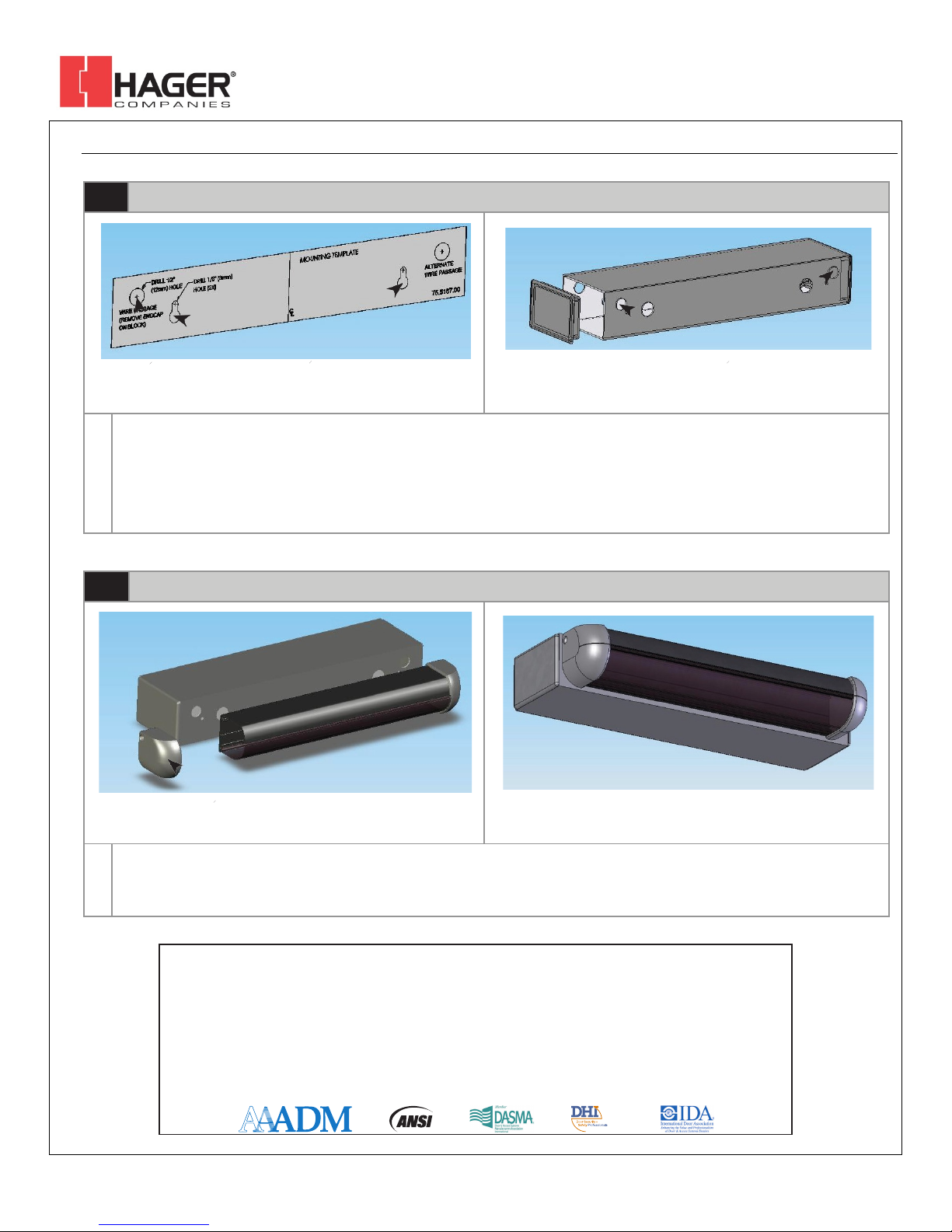
1
Mounting the Bodymount
WIRE MOUNTING
PASSAGE SCREW
HOLE HOLES
WIRE PASSAGE HOLES
1.
Place the adhesive mounting template on the appropriate surface, depending on the application.
2.
Then drill pilot holes for the wire passage and mounting screws as shown.
3.
Then partially drive the two Phillips head mounting screws into the small pilot holes.
4.
Remove the left endcap on the Bodymount. This will make it easier to route the wiring harness from the Bodyguard through to the operator.
5.
Then slide the extrusion over the mounting screws and using a screwdriver, finish tightening to attach the block.
2
Mounting the Bodyguard III
REMOVE ENDCAP TO ATTACH SENSOR
1.
Once the block is secure and the harness is routed (use two screws provided with sensor), attach the sensor to the mounting block.
2.
It is necessary to remove one endcap and the two lenses to attach the sensor.
3.
Finish by reinserting the lenses and center clip and replacing both the Bodyguard and Bodymount endcaps.
The sensor manufacturer cannot be held responsible for incorrect installations or inappropriate adjustments of the sensor/device; therefore, the sensor
manufacturer does not guarantee any use of the sensor outside of its intended purpose.
The sensor manufacturer strongly recommends that installation and service technicians be AAADM-certified for pedestrian doors, IDA-certified for
doors/gates, and factory-trained for the type of door/gate system.
Installers and service personnel are responsible for executing a risk assessment following each installation/service performed, ensuring that the sensor
system installation is compliant with local, national, and international regulations, codes, and standards.
Once installation or service work is complete, a safety inspection of the door/gate shall be performed per the door/gate manufacturer recommendations
and/or per AAADM/ANSI/DASMA guidelines (where applicable) for best industry practices. Safety inspections must be performed during each service
call – examples of these safety inspections can be found on an AAADM safety information label (e.g. ANSI/DASMA 102, ANSI/DASMA 107, UL 325).
Verify that all appropriate industry signage and warning labels are in place.
INSTALLATION/SERVICE COMPLIANCE EXPECTATIONS
Installation Instructions
I-EA00207
4. INSTALLATION
Rev 01, Rev Date: 05/08/2018 Page 2 of 2
Hager Companies 139 Victor Street, St. Louis, MO 63104 (800) 325-9995 www.hagerco.com
 Loading...