

Page 1

3800 Series Electric Mortise Lock Electrical
FUNCTION DESCRIPTION
3880EL - Fail Safe Control
Outside trim is locked when power is applied and unlocked when power is removed (storeroom function when energized). Lockset
will unlock in the event of a power failure.
3880EU - Fail Secure Control
Outside trim is unlocked when power is applied and locked when power is removed. Lockset will lock in the event of a power
failure. This is the default lock setup.
Note: 3882 will function the same as the 3880EL / EU, but both sides will lock/unlock simultaneously.
Key Function
When key cylinders are installed into locks, the latch bolt may be momentarily retracted from the outside with key even if lockset is
electrically locked.
Latch Bolt Monitoring
Latch Bolt Monitoring (LM) is a SPDT switch that is mounted inside the lockset. The LM switch monitors the full extension of the
main latch.
Request to Exit
Request to Exit (RX) is a SPDT switch that is mounted inside the lockset. The RX switch monitors the activation of the inside trim
when the lockset is in the locked position only.
Door Position Monitoring (DPM)
Door Position Monitoring is a SPDT magnetic reed switch that is mounted in lock body and reacts with a magnet in the strike to
monitor if the door is in the closed position.
ELECTRICAL SPECIFICATIONS
EL and EU
RX and LM
DPM
Motorized Locking / Unlocking at 12/24V
operation with low power consumption
Voltage: 12-24V AC/DC (11V – 30V)
Current: 250 mA MAX Inrush, 10 mA
MAX holding
Non-polarized leads
Fail Secure by Default
SPDT mechanical switch. Mainly used as
a dry contact monitoring switch.
Voltage Current
125 VAC 3 AMP
30 VDC 2 AMP
RX Wiring Diagram
Yellow Wire: (common)
Red Wire: (normally open)
Gray Wire: (normally closed)
LM Wiring Diagram
Black: (common)
Red: (closed loop secure)
White: (open loop secure)
SPDT Magnetic Reed Switch (used as a
dry contact monitoring switch)
Voltage: 28 VDC
Current: 0.300 A
DPM Wiring Diagram
WHITE WIRE – (COMMON)
RED WIRE – (OPEN LOOP SECURE)
GREEN WIRE – (CLOSED LOOP
SECURE)
2-Conductor Wire Run
Distance
12V/24V
Wire
Gauge
125’/250’
22
200’/400’
20
300’/600’
18
500’/1000’
16
750’/1500’
14
1250’/2500’
12
Specifications and Supplemental Instructions
I-LS02200
Quick Connect Assignments: See page 4 for detailed pinning information
REV 2, 04/18/2018 27390101 Page 1 of 4
Page 2

3800 Series Electric Mortise Lock Electrical
Non-polarized Leads
Default Fail-Secure (EU), Slide
White Switch from YELLOW to
GREEN to Make Fail-Safe (EL)
EL/EU
DPM
LM &/or RX
Activation Magnet
TOP
YELLOW
GREEN
White Switch Slider
Fail-Secure
(EU)
Fail-Safe
(EL)
NOTE: The colors indicate which direction to move the switch to select the desired function.
They are not position indicators. The switch should be easy to move, so don’t force it.
Specifications and Supplemental Instructions
I-LS02200
Wire Bundles:
See below for general location of wire bundles. Some or all of the bundles may be present depending on the functions ordered. When
wiring up, use wire color within the bundle to identify function (see page 1 for function / wire details).
Electrically Locked (EL) / Electrically Unlocked (EU)
This function comes EU by default, but can be easily changed to EL by sliding the White switch from YELLOW to GREEN as shown
below. The unit must have power applied at least once before the lockset changes state. Note that the latch bolt may be momentarily
retracted by key even if the lockset is electrically locked.
Door Position Monitoring (DPM)
Door position monitoring is an SPDT magnetic reed switch mounted inside the lockset with the activation magnet mounted behind the
ANSI strike plate. The magnet is positioned above the latch bolt, so orient the magnet plate per handing of opening to properly
position the magnet (see below for orientation).
LEFT HAND STRIKE PLATE RIGHT HAND STRIKE PLATE
REV 2, 04/18/2018 27390101 Page 2 of 4
Page 3

3800 Series Electric Mortise Lock Electrical
INSTRUCTIONS
Door and Frame Preparations
1. Follow mortise lock instructions and template to prepare door and frame for installation. Add ½” depth to the mortise
pocket as shown below. Since motor control is located inside the lockset, there are no special preparations or alterations
to the standard installation.
Door Raceway Preparations
1. Door raceway preparations are required to route electrical wires. See diagram below for raceway specifications.
2. Follow mortise lock instructions and template to complete installation.
3/8” Diameter Raceway *
* - Using Quick Connectors requires a
5/8” diameter raceway
Door fabricator to provide 3/8” diameter (5/8” for
quick connectors) (minimum) raceway through
door to allow insertion of electrical wires running
between the lock mortise and electric hinge.
Electrical Hinge
1”
[25.4]
3/4" Diameter
3”
1/2” Clearance
Specifications and Supplemental Instructions
I-LS02200
REV 2, 04/18/2018 27390101 Page 3 of 4
Page 4
3800 Series Electric Mortise Lock Electrical
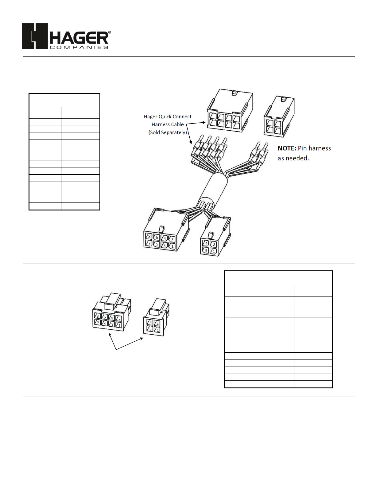
QUICK CONNECTS
Quick connects are installed on the wires from the mortise lock electrification options. These quick connects are compatible
with Hager Quick Connect Harness Cable which can be used to plug into Hager hinges with quick connects to provide
quick and accurate wiring of the door.
Quick Connect
Harness Cable Pinning
8 Pin
Wire Color
Pin #1
Black
Pin #2
Red
Pin #3
White
Pin #4
Green
Pin #5
Orange
Pin #6
Blue
Pin #7
Brown
Pin #8
Yellow
4 Pin
Color
Pin #1
Violet
Pin #2
Gray
Pin #3
Pink
Pin #4
Tan
3800 Quick Connect
Pinning
8 Pin
Function
Wire Color
Pin #1
Power*
Blue
Pin #2
Power*
Blue
Pin #3
RX (Com)
Yellow
Pin #4
RX (N/O)
Red
Pin #5
RX (N/C)
Gray
Pin #6
DPM (Com)
White
Pin #7
DPM (N/O)
Red
Pin #8
DPM (N/C)
Green
4 Pin
Function
Color
Pin #1
Blank
Blank
Pin #2
LM (Com)
Black
Pin #3
LM (N/O)
White
Pin #4
LM (N/C)
Red
Hager 3800 Mortise Lock
Quick Connect Terminals
Specifications and Supplemental Instructions
I-LS02200
REV 2, 04/18/2018 27390101 Page 4 of 4
 Loading...