


Montageanleitung
Mounting Instructions
Instructions de montage
Istruzioni di montaggio
Instrucciones de montaje
Dialock Türterminal DTSH, DTSH FH
Dialock Door Terminal DTSH, DTSH FH
Dialock Terminal de Porte DTSH, DTSH FH
Dialock Terminale Porta DTSH, DTSH FH
Dialock Terminal de Puerta DTSH, DTSH FH
EN
FR
IT
ES
DE

Dialock Door Terminals DTSH, DTSH FH - Status: 07.2008 - 732.29.134
37
English
Installation Instructions
Contents
Scope of delivery ..................................................................................39
Accessories (not included in the scope of delivery) .............................40
DTSH Application areas .......................................................................42
DTSH FH application areas .................................................................42
Features ...............................................................................................42
Installation instructions .........................................................................43
Start-up .................................................................................................63
Short instructions .................................................................................65
Operation ..............................................................................................66
Battery change .....................................................................................66
Emergency opening .............................................................................68
FAQ.......................................................................................................69
Maintenance and cleaning instructions ................................................69
Technical data ......................................................................................69

38
English
Dialock Door Terminals DTSH, DTSH FH - Status: 07.2008 - 732.29.134
Installation Instructions

Dialock Door Terminals DTSH, DTSH FH - Status: 07.2008 - 732.29.134
39
English
Installation Instructions
Always follow the instructions in the "Start-up and maintenance"
guide when starting up (assigning keys)!
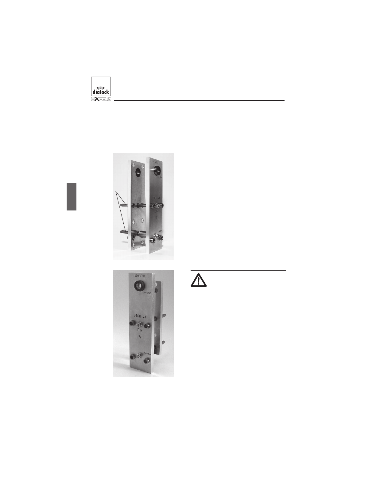
Scope of delivery
1 External module
1 Internal module
Small parts bag with
profile cylinder cover (break-open seal)
1 Promaseal strip (DTSH FH only)
Profile cylinder coverFig. 1
Profile cylinder
cover
Rotary knob
(fixed at hood)
Internal module External moduleFig. 3
Promaseal stripFig. 2
40
English
Dialock Door Terminals DTSH, DTSH FH - Status: 07.2008 - 732.29.134
Installation Instructions
Accessories (not included in the scope of delivery)
Accessories (not incl. in the scope of delivery) Cat. No.
Black plastic spacer plate 917.90.492
Stainless steel spacer plate for DTSH FH 917.90.216
Profile cylinder cover (break-open seal),
plastic, black
Optional:
Stainless steel matt
Stainless steel polished
Brass polished
25 pieces 917.90.483
917.90.480
917.90.481
917.90.488
User key: Different models
4 x 1.5 V batteries, size AA Mignon type E91
Energizer
®
Ultra+
910.54.980
Lever handle aperture part: Different models.
DTSH FH: Only supplied models may be used
(see catalogue).
Single profile cylinder:
Length depends on door leaf thickness.
Single profile cylinder must be fitted with DTSH FH!
Mortise lock: Different models
DTSH: Locks in accordance with DIN 18251.
DTSH FH: Locks in accordance with DIN 18273.
Dialock Door Terminals DTSH, DTSH FH - Status: 07.2008 - 732.29.134
41
English
Installation Instructions
Accessories (not incl. in the scope of delivery) Cat. No.
Mounting sets for DTSH
No. Door thickness Consisting of
1 37 – 47 mm 1 inner square spindle L=100mm 917.90.242
4 countersunk head screws
DIN 965 M4x30
für DTSH FH 917.90.121
2 47 – 57 mm 1 inner square spindle L=110mm 917.90.244
4 countersunk head screws
DIN 965 M4x40
for DTSH FH 917.90.122
3 57 – 67 mm 1 inner square spindle L=120mm 917.90.246
4 countersunk head screws
DIN 965 M4x50
for DTSH FH 917.90.124
4 67 – 77 mm 1 inner square spindle L=130mm 917.90.248
4 countersunk head screws
DIN 965 M4x60
for DTSH FH 917.90.126
5 77 – 87 mm 1 inner square spindle L=130mm 917.90.250
4 countersunk head screws
DIN 965 M4x70
for DTSH FH 917.90.128
6 87 – 97 mm 1 inner square spindle L=160mm 917.90.251
4 countersunk head screws
DIN 965 M4x80
for DTSH FH 917.90.130
7 97 – 107 mm 1 inner square spindle L=160mm on request
4 countersunk head screws
DIN 965 M4x90
for DTSH FH on request
42
English
Dialock Door Terminals DTSH, DTSH FH - Status: 07.2008 - 732.29.134
Installation Instructions
DTSH Application areas
The Dialock DTSH door terminal is an electronic door fitting for use in
hotels. It is mounted to internal doors with mortise locks in accordance
with DIN 18 251* and can also be easily retrofitted to the door leaf. The
use of a single profile cylinder is recommended for emergency openings.
* Mortice lock bolt-through fixing holes must be present (fig. 4, page 43)
Using the Dialock DTSH door terminal on fire resistant and smoke
control doors invalidates the Fire Certificate of the doors!
Please contact your Häfele sales office if you intend to use the door terminal on fire resistant and smoke control doors.
DTSH FH application areas
Permission from the door manufacturer is required to install the DTSH FH.
If the DTSH FH door terminal is installed without permission, the Fire Certificate for the fire resistant and smoke control door will be invalidated. The
fitting must always be installed by trained personnel.
Features
Robust metal housing
Convenient and easy to use
Automatic activation using the latest RF technology
"Do not disturb" function using lock handle
Battery operation using normal commercial batteries, size AA (Mignon)
Infrared interface for easy configuration
Easy to install
Optional: Mechanical emergency opening is logged
(appropriate mortise lock required)
Dialock Door Terminals DTSH, DTSH FH - Status: 07.2008 - 732.29.134
43
English
Installation Instructions
Installation instructions
DTSH:
Do not mount to fire resistant and smoke control doors!
Please contact your Häfele sales office.
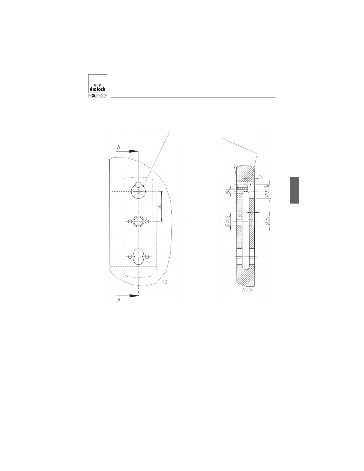
Installation requirement
The doors must be prepared for the use of DIN 18 251 locks (lock pocket
and mortise lock).
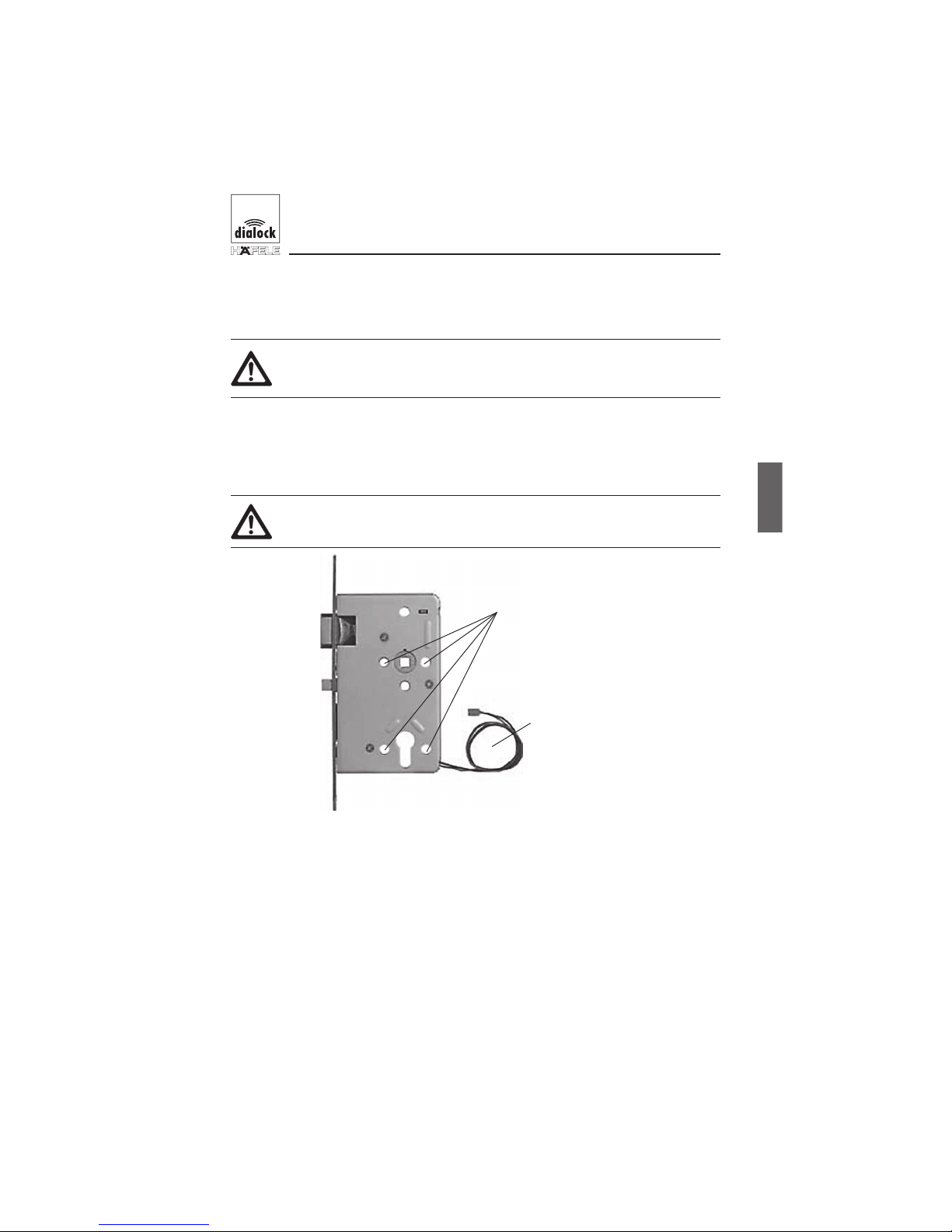
The mortise lock must have the depicted Mortice lock bolt-through
fixing holes for the fitting.
Fig. 4
The length of the following Dialock DTSH door terminal components
depends on the thickness of the door leaf. They must therefore be selected
accordingly.
Mounting set consisting of: Fixing screws and inner square spindle (for
scope of delivery see page 39).
Single profile cylinder (not included in the scope of delivery).
Cable only required for mortise
locks with emergency opening
log.
Mortice lock bolt-through fixing holes

44
English
Dialock Door Terminals DTSH, DTSH FH - Status: 07.2008 - 732.29.134
Installation Instructions
The black plastic profile cylinder cover is also a break-open seal and
must not be fitted until start-up has taken place.
Do not bring media (keys) into the reading area during installation if
the batteries have been inserted!

Dialock Door Terminals DTSH, DTSH FH - Status: 07.2008 - 732.29.134
45
English
Installation Instructions
Tools
Tools Cat. No.
Locking ring pliers (for fitting locking
ring to inner square spindle)
917.90.900
SW3 T-handle for
grub screws of lever handle aperture part
and removing the inner hood
006.32.013
DTSH DIN drilling jig 917.90.005
Router cutter for breakthrough to lock
nut
Ø 25 mm 910.54.995
Router cutter
with centring pin
only needed for
mortise lock with
mergency opening logging)
Fig. 5
Ø 32 mm 910.54.997
Stop for router cutter
(only needed for mortise lock with emergency opening log)
Fig. 6
32 mm 001.28.129
Drill bits
(cable leadthrough)
Fig. 7
13 mm 001.41.351
Drill
(Fastening spots)
8 mm 001.41.248
Drill
Cross slot screwdriver size 2 006.28.382

46
English
Dialock Door Terminals DTSH, DTSH FH - Status: 07.2008 - 732.29.134
Installation Instructions
Installation
Condensation that forms on cold components can damage the
Dialock DTSH door terminal.
ð Please ensure that all components are at ambient temperature!
The way in which the fitting is mounted to wooden doors is described in
the following.
Please adhere to the following procedure when installing the Dialock
DTSH door terminal:
Insert mortise lockA. Page 47
Drill holes for fixing screws and connecting cableB. Page 48
Remove mortise lock, clean and re-insertC. Page 53
Insert single profile cylinderD. Page 54
Adjust external module for right-pointed/left-pointed door E.
handle
Page 56
Secure inner square spindleF. Page 57
Mount external module of Dialock DTSH door terminalG. Page 58
Mount internal moduleH. Page 60
Fig. 8
With emergency opening
log, protect connecting cable
during the drilling procedure
as shown in the illustration.

Dialock Door Terminals DTSH, DTSH FH - Status: 07.2008 - 732.29.134
47
English
Installation Instructions
Insert mortise lockA.
Risk of the cable being crushed by mortise lock with emergency
opening log!
Insert mortise lock.1.
Fig. 9
cable
Fig. 10
cable
Fig. 11
Hooded
screw
Fig. 12
Screw in the mortise lock. 2.
With mortise lock with emergency opening log, the mortise lock connecting cable must be fixed in position as shown in fig. 11.
Check position of mortise lock using a locking cylinder. The locking cyl-3.
inder must be easy to insert. If necessary, increase size of lock pocket
or clear the locking cylinder access route.
incorrect
correct

48
English
Dialock Door Terminals DTSH, DTSH FH - Status: 07.2008 - 732.29.134
Installation Instructions
B. Drill holes for fixing screws and connecting cable
In order to obtain a neat drill hole, the through holes should first be
part drilled from one side of the door to the middle of the door leaf
and then drilled through from the other side of the door.
Preparing for drilling
Without emergency opening log
Drilling pattern without emergency opening logFig. 13
Cable drill hole
Ø 13 mm, continuous
for connecting cable for external /
internal module
Depth cutting
Ø 25 mm:
external only: 7 mm deep
4 x fixing holes
Ø 8 mm, continuous
Outer contour
DTSH
Dialock Door Terminals DTSH, DTSH FH - Status: 07.2008 - 732.29.134
49
English
Installation Instructions
Depth cutting only needed for Fig. 14
emergency opening log
Depth cutting to lock pocket Ø 32 mm
Centring hole for
router cutter with
centring pin
Space for
coupling
Inside of
door
Outside of
door
Section:
Drilling pattern with Fig. 15
emergency opening
logging
Only for emergency opening log
50
English
Dialock Door Terminals DTSH, DTSH FH - Status: 07.2008 - 732.29.134
Installation Instructions
Drilling jig parts A-BFig. 16
Select drilling jig with part A-B and 1.
A-C for the individual drill holes:
Insert centring pins for drilling jig 2.
(part A) through the square spindle
and cylinder apertures of the mortise lock. (Fig. 16)
Place drilling jig part B onto the 3.
centring pins from the other side
of the door. Clamp drilling jig into
position using a screw-clamp.
Drilling jig parts A-CFig. 17
Do not damage surface of
door.
Use drilling jig
The drilling jig consists of parts A, B and C. The drilling template must be
prepared in combinations A-B and A-C depending on the drill hole.
Centring
pins
Dialock Door Terminals DTSH, DTSH FH - Status: 07.2008 - 732.29.134
51
English
Installation Instructions
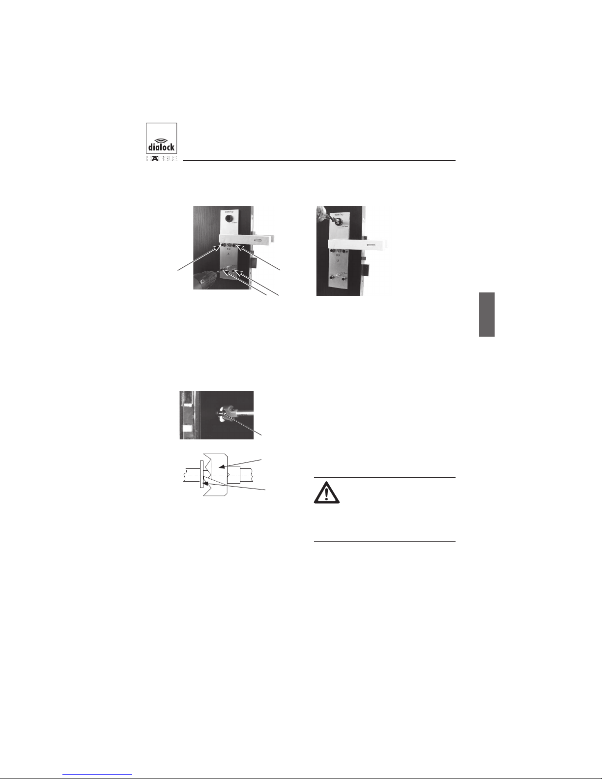
Drill holes on inside of door
Fig. 18 Fig. 19
Drill the fixing holes at both sides
as far as the middle of the door leaf
using the 8 mm drill bit.
Drill 13 mm hole at both sides for
cable connection.
Fig. 20
Fig. 21
Cut out the coupling area.
Note:
Cutting only required on the outside.
Do not damage mortise
lock with router cutter.
Slide the spacer onto the
journal of the router cutter to prevent damage.
(Fig. 20, 21)
Spacer
25 mm router
cutter
25 mm router
cutter
Spacer

52
English
Dialock Door Terminals DTSH, DTSH FH - Status: 07.2008 - 732.29.134
Installation Instructions
Only required with emergency opening log!
Drilling jig parts A-CFig. 22
Drill through to the middle of the door
leaf from both sides using the 8 mm
drill bit to connect the emergency
opening log. (Centring hole for 32 mm
router cutter)
This procedure can
destroy the connecting
cable for emergency
opening log. The connecting cable must not
be routed in the lock
pocket at location A,
fig. 22!
Fig. 23
Remove mortise lock
from lock pocket!
Depth cutting as far as lock pocket.
Page 49, fig. 15, section A-A.
A

Dialock Door Terminals DTSH, DTSH FH - Status: 07.2008 - 732.29.134
53
English
Installation Instructions
C. Remove mortise lock, clean and re-insert
Fig. 24
Remove mortise lock.
Outside of door is already drilled and cut.
Before continuing, remove debris
and clean lock pocket.
With emergency
opening log, lead connecting cable into the
inside of the lock pocket and out via the hole
that has been cut.
Fig. 25
Pay attention to cable routing when inserting the connecting cable!
Do not crush cable! (Fig. 25)
Insert mortise lock as described in "A. Insert mortise lock" on page 47.
Connection cable
Depth cutting
Door leaf
Connector
Mortise lock
Lock pocket

54
English
Dialock Door Terminals DTSH, DTSH FH - Status: 07.2008 - 732.29.134
Installation Instructions
D. Insert single profile cylinder
Failure to follow these instructions will destroy the single profile
cylinder and the lock.
Do not use force.
Only use one single profile cylinder with the correct length!
(See fig. 26)
A
a1
a2
External fitting
Door leaf
Single profile cylinder
Forend screw
Important when ordering:
A = a
1
+ a
2
a1 = inner fitting height:
Recess in fitting for single profile cylinder
at least 19 mm to a maximum of 24 mm.
a
2
= Distance between middle of forend screw and door leaf surface.
Fig. 26

Dialock Door Terminals DTSH, DTSH FH - Status: 07.2008 - 732.29.134
55
English
Installation Instructions
The follower must be in the correct position!
Otherwise the switching mechanism will be damaged.
The follower only needs to be adjusted with a mortise lock with emergency opening log.
Adjust follower of single profile cylinder as shown
in the illustration on the right. The follower should
always point in the direction of the door hinge.
The position of the single profile cylinder should be checked carefully before screwing in the forend screw (page 47, fig. 12).
The forend screw supplied with the single profile cylinder must be
used with emergency opening log. The length of the forend screw
should not exceed the backset + max. 10 mm, otherwise the emergency opening log sensor may be destroyed..
Slide single profile cylinder into door lock until forend 1.
screw can be screwed in from the edge of the door.
Check whether the follower (locking lug) rotates
smoothly when the key is turned. Otherwise correct the
position of the single profile cylinder.
Tighten single profile cylinder with forend screw. 2.
Re-check whether the follower (locking lug) rotates
smoothly when the key is turned. Otherwise correct the
position of the single profile cylinder.
The single profile cylinder is only used for emergency opening, not for
locking.
Attempting to lock the door using force may damage the mortise lock!
45
o
Fig. 28
Fig. 27
Fig. 29

56
English
Dialock Door Terminals DTSH, DTSH FH - Status: 07.2008 - 732.29.134
Installation Instructions
E. Adjust external module for right-pointed/left-pointed door handle
The Dialock DTSH FH door terminal is supplied already set up and
must not be modified.
Place lever handle aperture part onto outer square spindle of external
module so that the direction of movement matches the application.
Fig. 30
Right-pointed door handle,
zero position
Fig. 31
Left-pointed door handle leftside
zero position
Rotate outer square spindle with lever handle aperture part to upper 1.
stop position (zero position) and hold.
Gently knock pin (3 x 24) mm into the hole marked "R" or "L" with a 2.
hammer. Set stop limit by inserting pin into "R45" or "L45" hole.
Secure pins with stickers so that they do not fall out.3.
The spring of the lever handle aperture part is pre-tensioned.

Dialock Door Terminals DTSH, DTSH FH - Status: 07.2008 - 732.29.134
57
English
Installation Instructions
F. Secure inner square spindle
Rotate marking (lug) (1) of coupling 1.
part in direction V (2).
Before inserting the inner square spindle into the cou-2.
pling part, align it so that the groove of inner square
spindle and the grub screw of the lever handle aperture
part are pointing in the same direction.
Insert inner square spindle in inner coupling part so that 3.
the pins are sitting in the recesses in the coupling part.
Insert locking ring into groove in the 4.
inner coupling part with locking ring
pliers. Ensure that the opening of the
locking ring is not above any of the
abovementioned inner square spindle
pins. (Fig. 36)
The inner square spindle is now installed.
After the inner square spindle has been installed in the external module, the marking (lug) of the coupling part must always be pointing in
direction V. The inner square spindle must not be twisted when it is
inserted in the door lock.
Fig. 32
Inner square spindle Fig. 33
with groove
Fig. 34
Fig. 35 Fig. 36
1 "Lug"
2 Arrow marking

58
English
Dialock Door Terminals DTSH, DTSH FH - Status: 07.2008 - 732.29.134
Installation Instructions
G. Mount external module of Dialock DTSH door terminal
Fig. 37
The following prerequisites must be complied
with:
Holes drilled as per drilling plan
Door lock and locking cylinder inserted
If the distance between the surface of the door
leaf (outer) and the lock case is less than 6 mm a
spacer plate must be used, otherwise the external
module will be touching the lock cover.
Always use a stainless steel spacer
plate with DTSH FH - plastic is not
allowed!
Fig. 38
Fig. 39
Before putting on the external module, check 1.
whether the lug of the coupling part is pointing
in direction V (see fig. 36, page 57).
Insert inner square spindle into lever follower 2.
(fig. 38) and lead connecting cable through top
hole (13 mm). It is imperative to pay attention
to the cable routing!
If a mortise lock with emergency opening log is 3.
being used, attach connecting cable to connector in external module and roll up connecting
cable in the 32 mm recess.

Dialock Door Terminals DTSH, DTSH FH - Status: 07.2008 - 732.29.134
59
English
Installation Instructions
Fig. 40
Do not trap cable!
Vertically align external module so that the 4.
guide pins of the external module engage in the
holes.
Slide external module towards door leaf until it 5.
is lying flat against it. (Fig. 40)
If the external module does not lie flat against the
door:
ð Check drill holes and remove wood debris if
necessary.
The external module is now installed.

60
English
Dialock Door Terminals DTSH, DTSH FH - Status: 07.2008 - 732.29.134
Installation Instructions
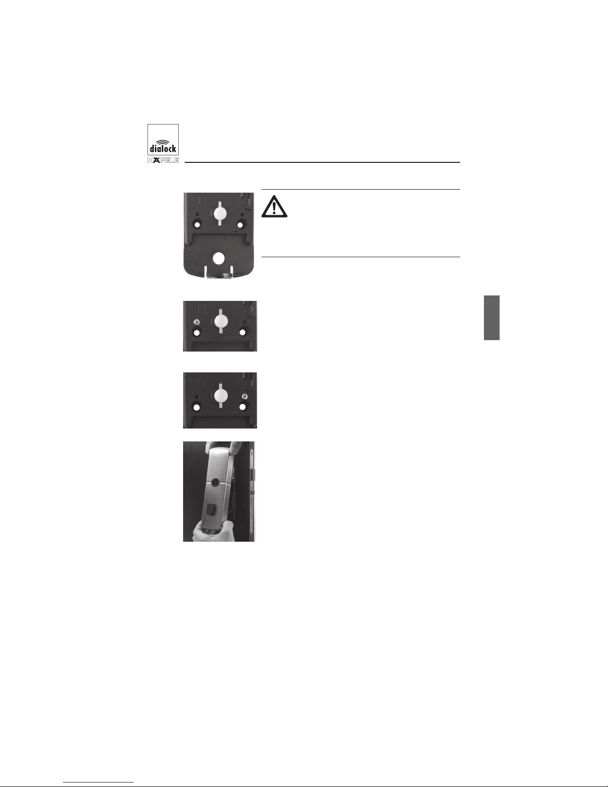
H. Mount internal module
Fig. 41
Fig. 42
Fig. 43
Risk of crushing!
Pay attention to cable routing!
Line 13 mm DTSH FH cable hole with Proma-1.
seal strips, shorten to door leaf thickness and
glue in parallel to cable.
Lead connector of connecting cable through 2.
opening in internal module fixing plate, fig. 42.
Place internal module fixing plate on inside of 3.
door leaf.
Loosely secure fixing plate using the four fixing 4.
screws.
Check vertical alignment at internal and exter-5.
nal module and then tighten fixing screws.
Plug connector of connecting cable into socket 6.
above battery holder and roll up connecting
cable as shown in fig. 43.
Insert battery into battery holder. 7.
Pay attention to correct polarity!
Dialock Door Terminals DTSH, DTSH FH - Status: 07.2008 - 732.29.134
61
English
Installation Instructions
Fig. 44
Fig. 45
Fig. 46
Fig. 47
Pay attention to position of
"Do not disturb" rotary knob!
The rotary knob must be vertical during
installation and the grooved side of the
square spindle at the internal module
must point in the direction of the forend.
The direction of rotation of the "DND" lever can 8.
be set to right or left if required.
Fig. 44: Direction of rotation right/left
without screw
Fig. 45: Direction of rotation left
with screw position A
Fig. 46: Pivot direction right
with screw position B
Remove hood of internal module. With long 9.
door handle pins, slide the hood onto the
square spindle first.
A
B

62
English
Dialock Door Terminals DTSH, DTSH FH - Status: 07.2008 - 732.29.134
Installation Instructions
Fig. 48
And tighten screw.10.
Always use the original grub screws in
the provided small parts bag.
ð Remove other grub screws from lever
handle aperture part if necessary.
Always use the provided lever handle with
the DTSH FH.
The small parts bag for the FH version
does not contain any grub screws. The
screws of the lever handle are used in
this case.
Mount inner and outer lever handle to the rel-11.
evant square spindle and tighten grub screws
using Allen key (3 mm).
Fig. 49
The internal and external modules are now installed
A mechanical check must be performed when assembly is complete.
Push the lever handle on the inside of the door to operate the mortise lock:
ð Pull back the latchbolt (escape function), or the latchbolt and deadbolt,
depending on the type of mortise lock.
Push the lever handle on the outside:
The coupling is disconnected, i.e. the lever handle has no effect, but it
must be automatically returned to the horizontal idle position via the return
spring. If this is not the case, check the individual assembly steps
DTSH FH:
Have confirmation of installation signed by fitter as documentation
for the customers's construction file.

Dialock Door Terminals DTSH, DTSH FH - Status: 07.2008 - 732.29.134
63
English
Installation Instructions
Start-up
The Dialock DTSH door terminal is supplied in so-called "simple mode"
for standalone operation (SA). This is the only operating mode that is
described in these instructions. Details about the use of the DTSH in conjunction with software applications (Dialock HOTEL, PERSONNEL, hotel
management systems etc.) can be found in the relevant documentation.
Prevent use of user keys by unauthorised persons.
Keep the programming and clearing keys in a safe place, since locking authorisations can be allocated to and withdrawn from a user key
with these two keys.
The programming and clearing keys must be assigned as follows during
initial start-up:
This step is only possible after switching on for the first time.
Perform the initial start-up quickly and without interruptions!
Have green programming key and red clearing key ready.1.
Present the green programming key to the control panel until the blue 2.
LED is permanently on. An acoustic signal will be heard.
Remove programming key: Red LED flashes.3.
Present red clearing key to the control panel whilst red LED is flashing.4.
64
English
Dialock Door Terminals DTSH, DTSH FH - Status: 07.2008 - 732.29.134
Installation Instructions
If no red clearing key is presented to the control panel within 5 seconds, the procedure will be automatically interrupted.
The red clearing key must be presented to the control panel again to
complete the initial start-up.
When the key has been trained successfully, the LED will be perma-5.
nently blue and an acoustic signal will be heard. The Dialock DTSH
door terminal then goes into normal operating mode.
If persistent errors occur:
ð Notify the service location.

Dialock Door Terminals DTSH, DTSH FH - Status: 07.2008 - 732.29.134
65
English
Installation Instructions
Short instructions
Allocate locking authorisations to user key
Present green programming key to the control panel. 1.
ð Blue LED flashes.
Present user key that has to be trained to the control panel for 5 sec-2.
onds. The locking authorisations for the user key have been allocated
when the blue LED flashes briefly.
Remove trained user key.3.
Present the next user key to be trained to the control panel within 4.
5 seconds.
Withdraw locking authorisations from user key
Present red clearing key to the control panel. 1.
ð Red LED flashes.
Present user key that has to be cleared to the control panel. When 2.
the red LED flashes briefly, the locking authorisations have been withdrawn. The Dialock DTSH door terminal then goes into normal operating mode.
If no more keys are presented to the control panel the DTSH goes
into the normal operating mode.
Withdraw locking authorisations from all user keys
If a user key has been lost and you wish to cancel its locking authorisations, all user keys must first be deleted at the Dialock DTSH door terminal. Access rights must then be re-allocated to all user keys with locking
authorisations.
Present red clearing key to the control panel. 1.
ð Red LED flashes.
Present green programming key to the control panel. 2.
ð Red LED flashes briefly.
Re-allocate access rights to all user keys that are still to have locking 3.
authorisations.
66
English
Dialock Door Terminals DTSH, DTSH FH - Status: 07.2008 - 732.29.134
Installation Instructions
Operation
Present user key to the control panel - red LED flashes briefly. An 1.
acoustic signal will be heard. If the user key does not have locking
authorisation the signal will be heard twice.
The blue LED flashes and the red LED goes off.2.
The Dialock DTSH door terminal is ready for opening for approx. 3 sec-3.
onds. The door can be opened by pushing the lever handle.
If the LEDs do not change from red to blue: 4.
ð Present user key closer to control panel.
If the LEDs still do not change from red to blue: 5.
ð User key is not authorised
Battery change
If the battery charge is low, the red and blue LED flash alternately three
times when the electronics are switched on.
ð A battery change is recommended.
The date and time are saved when the battery is removed, and reloaded
again after new batteries have been inserted. The clock stops for the duration of the battery change.
ð Replace batteries quickly!
If the time needs to be accurate to the minute, the date and time can be
corrected with the Dialock MDU (only of interest for operation with the personnel and hotel software!).
However, the user keys always retain their authorisation.
Smooth operation of the Dialock DTSH door terminal is only guaranteed, if weak batteries are replaced immediately. Always use highquality batteries.

Dialock Door Terminals DTSH, DTSH FH - Status: 07.2008 - 732.29.134
67
English
Installation Instructions
Do not throw batteries in the household waste!
ð Dispose of batteries in an environmentally friendly way, e.g. using a
municipal collection point.
The following steps are required to change the batteries:
The batteries are located in the internal module of the Dialock DTSH door
terminal.
Loosen the grub screw of lever handle aperture part at the inside of the 1.
door using an Allen key.
Pull lever handle aperture part from inner square spindle.2.
Loosen screw from underside of internal module.3.
Remove hood of internal module.4.
Remove old batteries.5.
Insert new batteries into battery holder as quickly as possible. 6.
Ensure that the polarity is correct (see figure 43, page 60)!
Re-attach hood of internal module and tighten screw on underside of 7.
internal module.
Mount lever handle aperture part to inner square spindle and tighten 8.
grub screw using Allen key.

68
English
Dialock Door Terminals DTSH, DTSH FH - Status: 07.2008 - 732.29.134
Installation Instructions
Emergency opening
Push in break-open seal (profile cylinder cover) with a small screw-1.
driver and remove.
Open Dialock DTSH door terminal using an emergency opening key.2.
Insert new break-open seal.3.
The single profile cylinder is only used for opening, not for locking.
Attempting to lock the door using force may destroy the emergency
opening log facility!
Fig. 50

Dialock Door Terminals DTSH, DTSH FH - Status: 07.2008 - 732.29.134
69
English
Installation Instructions
FAQ
I've lost a user key and want to block it.
What should I do?
If a user key has been lost and you wish to cancel its locking authorisations, all user keys must first be deleted at the Dialock DTSH door terminal. Access rights must then be re-allocated to all user keys with locking
authorisation.
See under: "Withdraw locking authorisations from all user keys".
Maintenance and cleaning instructions
The DTSH is maintenance-free apart from having to change the batteries.
No lubricants must be introduced into the DTSH. These could destroy sensitive components and cause the DTSH to fail.
Do not use scouring agents to clean the surface of the DTSH. If necessary, use a dry, soft cotton cloth or a soft cloth moistened with a mixture of
water and washing up liquid or neutral cleaner. Do not use cleaning agents
containing alcohol or other organic solvents or thinner under any circumstances.
Technical data
Dimensions (26 x 65 x 227) mm ((L x W x H)
Power supply 4 x 1.5 V batteries, size AA Mignon
type E91 Energizer
®
(Cat. No.: 910.54.980)
Temperature range 0 – 65°C
Humidity 0 – 90%, not condensed
Right reserved to make technical changes.
 Loading...