


Dialock Zylinder DC
Dialock Cylinder DC
GB
D
Montage- und Kurzanleitung
Mounting and Brief Operating Instructions

17
Mounting and Brief Operating Instructions
English
Dialock Cylinder DC - Status: 09.2003 - 732.29.140
Contents
Scope of delivery . . . . . . . . . . . . . . . . . . . . . . . . . . . . . . . . . . . . . . . 16
Area of application . . . . . . . . . . . . . . . . . . . . . . . . . . . . . . . . . . . . . . 17
Conditions for installation . . . . . . . . . . . . . . . . . . . . . . . . . . . . . . . . . 17
Instructions for installation . . . . . . . . . . . . . . . . . . . . . . . . . . . . . . . . 18
Commissioning . . . . . . . . . . . . . . . . . . . . . . . . . . . . . . . . . . . . . . . . . 22
Brief operating instructions . . . . . . . . . . . . . . . . . . . . . . . . . . . . . . . . 23
Operation. . . . . . . . . . . . . . . . . . . . . . . . . . . . . . . . . . . . . . . . . . . . . . 24
Replacement of batteries . . . . . . . . . . . . . . . . . . . . . . . . . . . . . . . . . 25
Emergency opening . . . . . . . . . . . . . . . . . . . . . . . . . . . . . . . . . . . . . 26
RESET . . . . . . . . . . . . . . . . . . . . . . . . . . . . . . . . . . . . . . . . . . . . . . . 27
17

18
Mounting and Brief Operating Instructions
English
Dialock Cylinder DC - Status: 09.2003 - 732.29.140
Scope of delivery
• Cylinder with outside and inside knob
• Two 3 volt lithium batteries (art. no. 560-0004-03000) (8)
• Forend (11)
• O-ring (2) for front cover (1)
• Grub screws (7)
• Contact bridge (9)
Optional:
• Instructions for Installation and Operation
with Allen key 2 mm and 0.9 mm
1 Front cover
2 O-ring
3 Knob screw (
Allen screw)
4 Outer knob
5 Connection wire
6 Cylinder
7 Grub screws
8 Batteries
9 Contact bridge
10 Inner knob
11 Forend
12 Mortise lock

19
Mounting and Brief Operating Instructions
English
Dialock Cylinder DC - Status: 09.2003 - 732.29.140
Area of application
The Dialock DC Cylinder is convenient and easy to use and is part of the
Dialock Electronic Locking System. It is an electronic locking cylinder for
indoor installation with mortise locks to DIN 18 251. It is possible to
replace an existing standard locking cylinder with the Dialock DC Cylinder.
Conditions for installation
Important!
To install the Dialock DC Cylinder, use only a cylinder of the correct
inner and outer length (distance A and B). When measuring the cylinder lengths, the height of the inner and outer lock rosettes must be
taken into account.
The dimensions A and B are
important when ordering.
A = outer dimension (mm):
distance between the outer
edge of the inner rosette and
the centre of the hole for the
forend.
B = inner dimension (mm):
distance between the outer
edge of the inner rosette and
the centre of the hole for the
forend.
Door panel
Outer edge of
inner rosette
Outer edge of
outer rosette
Hole for forend
20
Mounting and Brief Operating Instructions
English
Dialock Cylinder DC - Status: 09.2003 - 732.29.140
Instructions for Installation
Important!
The Dialock DC Cylinder should be installed only by a qualified person. Non-compliance with these instructions may cause serious
damage to the Dialock DC Cylinder.
Do not close the door before carrying out all of the following steps.
Otherwise it will not be possible to open the door from the outside.
Note: The Dialock DC Cylinder is already greased by the manufacture. Further lubrication is not required.
1. Using a suitable tool, release the front cover (1) from the outer knob (4)
and carefully pull it out. The front cover (1) is secured against twisting
by means of a groove..
Important:
Take care not to damage the connection wire (5).
2. Using the Allen key, unscrew the two screws (3) inside the outer knob
(4) and remove the outer knob (4).
Important:
Take care not to damage the connection wire (5).
3. From the inside of the door, push the connection wire (5) through the
lock (12). Push the cylinder (6) into the lock (12) until the forend (11)
can be screwed in from the edge of the door.
21
Mounting and Brief Operating Instructions
English
Dialock Cylinder DC - Status: 09.2003 - 732.29.140
Important:
Check the position of the cylinder (6) before screwing in the forend.
Do not use force. Non-compliance with these instructions may
irreparably damage the cylinder (6) and the lock (12).
4. Tighten the cylinder (6) with the forend (11). Check that the catch turns
smoothly when the inner knob (10) is turned.
5. Push the connection wire (5) through the slot in the outer knob.
6. Push the front cover (4) onto the outside of the cylinder (6) and screw
the two screws (3) hand tight using the Allen key.
Important:
When pushing into position, the outer knob (4) must not be twisted,
otherwise the connection wire (5) may be damaged.
7. Push the O-ring (2) into the groove on the front cover (1).

22
Mounting and Brief Operating Instructions
English
Dialock Cylinder DC - Status: 09.2003 - 732.29.140
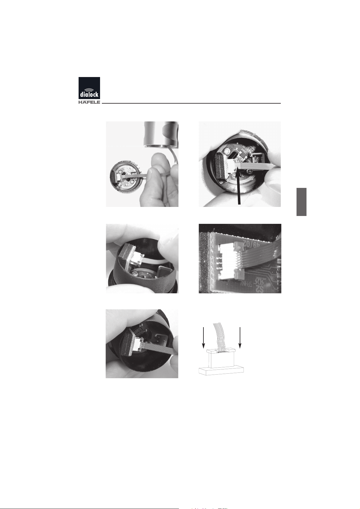
8. On the inside of the front cover (1) there is a terminal (A). Push the end
of the connection wire (5) into the terminal (A). When pushing into, the
non-insulated cable side (silvery) must be visible.
Do not use force!
The locking device is open (manufacturer's setting)
The connection wire (5) can be inserted.
If the locking is closed, it is not possible to insert the connecting cable. In
this case, the locking device must first
be pulled carefully out.
A
5
B
1
23
Mounting and Brief Operating Instructions
English
Dialock Cylinder DC - Status: 09.2003 - 732.29.140
1
2
3
4
5 6
silvery

24
Mounting and Brief Operating Instructions
English
Dialock Cylinder DC - Status: 09.2003 - 732.29.140
The connecting cable is correctly
inserted and the locking device is
correctly closed.
9. Press the front cover (1) onto the outer knob (4). Important: observe
the correct position of the groove (twist guard). Take care not to kink
or damage the connection wire.
The outer knob is now fully installed.

25
Mounting and Brief Operating Instructions
English
Dialock Cylinder DC - Status: 09.2003 - 732.29.140
10. Insert the batteries provided (8).
Ensure they are inserted correctly!
11. Push the contact bridge (9) into position.
12. Place the inner cover (10) in position and using the Allen key, screw
the three grub screws (7) hand tight.
The inner knob is now fully installed.
13. Function test: press the white button on the panel. The
LED panel flashes green 5 times and then red 5 times
(first use only).
26
Mounting and Brief Operating Instructions
English
Dialock Cylinder DC - Status: 09.2003 - 732.29.140
Commissioning
Important:
Before closing the door, carry out the following steps to use the lock
for the first time. Otherwise it will not be possible to open the door
from the outside.
When using for the first time, the green programming key and the red
cancelling key must be assigned as follows:
1. Keep the green programming key and the red cancelling key ready for
use.
2. Press the white button on the panel.
The green LED flashes for a few seconds.
3. While the green LED is still flashing, hold the green programming key
in front of the panel. If the teaching operating is successful, the green
LED lights up for a moment and then the red LED begins to flash.
4. While the red LED is still flashing, hold the red cancelling key in front
of the panel. If the teaching operating is successful, the green LED
lights up and then the electronics switch off.
5. If an error has occurred in the assigning operation, switch the Dialock
DC Cylinder on again and repeat the process from step 2 onwards. If
errors occur again, contact the Dialock agent.
Important:
Avoid misuse of the programming, cancelling and user keys by unauthorised persons. Always keep the programming, cancelling and user
keys in a safe place.

27
Mounting and Brief Operating Instructions
English
Dialock Cylinder DC - Status: 09.2003 - 732.29.140
Brief operating instructions
The Dialock DC Cylinder is supplied in the so-called "single mode" for
stand-alone (SA) operation. Only this mode is described in these instructions. For other modes, contact the manufacturer Häfele.
Assigning rights to user key
1. Press the white button on the panel.
The red LED lights up.
2. Hold the green programming key in front of the panel.
The green LED flashes.
3. Hold the user key to be taught in front of the panel within 5 secs. The
green LED lights up for a moment. Locking rights have now been
assigned to this user key.
4. Remove the first user key. Hold the user key to be taught in front of
the panel within 5 secs. If no further user key is held in front of the
panel.
The Dialock DC Cylinder switches off automatically.
Withdrawing rights to user key
1. Press the white button on the panel.
The red LED lights up.
2. Hold the red cancelling key in front of the panel.
The red LED flashes.
3. Hold the user key to be cancelled in front of the panel. The red LED
lights up for a moment. Locking rights have now been withdrawn.
The Dialock DC Cylinder switches off automatically.

28
Mounting and Brief Operating Instructions
English
Dialock Cylinder DC - Status: 09.2003 - 732.29.140
Withdrawing rights to all user keys
Should a user key be mislaid and no longer have locking rights, it is necessary to cancel all user keys. Locking rights must then be re-assigned to
the remaining authorised user keys. Refer to the section "Assigning rights
to user key".
1. Press the white button on the panel.
The red LED lights up.
2. Hold the red cancelling key in front of the panel.
The red LED flashes.
3. Hold the green programming key in front of the panel. The red LED
lights up for a moment. All locking rights have now been withdrawn.
Operation
1. Press the white button on the panel.
The red LED lights up.
2. Hold the user key in front of the panel.
3. The Dialock DC Cylinder can be opened within 3 secs. Turn the outer
knob to open the lock.
If the LEDs do not switch from red to green: => hold the user key closer
to the Dialock DC Cylinder. If the LEDs still do not switch from red to
green: => user key has no authorisation.
Important:
The cylinder does not lock automatically. The door has to be locked
manually from the inside or the outside.

29
Mounting and Brief Operating Instructions
English
Dialock Cylinder DC - Status: 09.2003 - 732.29.140
Replacement of batteries
When the batteries no longer have sufficient power, the red and green
LEDs flash alternately three times after switching on.
Important:
The Dialock DC Cylinder will only function correctly when exhausted
batteries are replaced immediately.
1. Unscrew the three grub screws (7) and pull off the inner knob (10).
2. Remove the contact bridge.
3. Insert the new batteries. Ensure they are inserted the right way
round!
4. Push the contact bridge (9) back into position.
5. Place the inner knob (10) in position and using the Allen key, screw the
three grub screws (7) hand tight.
6. Function test: Press the white button on the panel. The red LED must
light up briefly.
30
Mounting and Brief Operating Instructions
English
Dialock Cylinder DC - Status: 09.2003 - 732.29.140
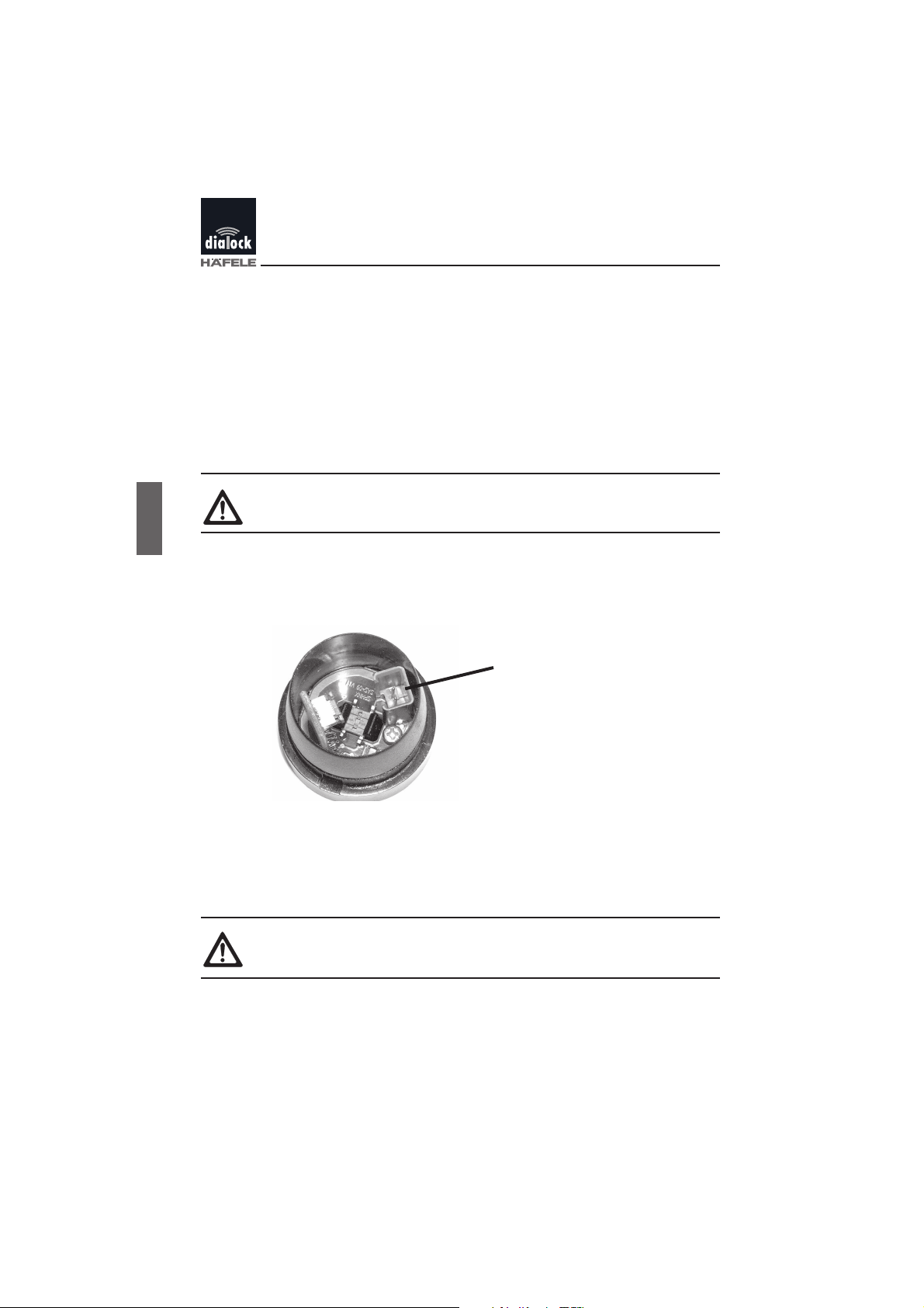
Emergency opening
Should the batteries discharge absolutely (e.g. because the "battery low"
signal has been ignored) or be defective, and the electronics fail to
respond, they can be powered externally by an optional emergency power
supply (art. no. 916.94.001).
1. Using a suitable tool, release the front cover (1) from the outer knob (4)
and pull it carefully off.
Important:
Take care not to damage the connection cable (5)!
2. Push the cable for the emergency power supply onto the emergency
power terminal (A) of the aerial board. The electronics switch on automatically.
3. Hold the authorised key in front of the panel.
4. The Dialock DC Cylinder is ready. Turn the outer knob to open the
lock.
5. Disconnect the emergency power supply and replace the cover.
Important:
Take care not to damage the connection cable (5)!
6. Replace the batteries immediately (see "Replacing batteries",
page 25).
A

31
Mounting and Brief Operating Instructions
English
Dialock Cylinder DC - Status: 09.2003 - 732.29.140
RESET
Note: It is only possible to execute RESET from inside.
1. Unscrew the two grub screws (7) and pull off the inner knob (10).
2. Using metal tweezers or the reset tool, bridge pins 1 and 2. The
RESET process is described below.
3. Following the reset, replace the inner knob (10) and screw it into place
with the three grub screws (7).
RESET process:
When the reset contact points (A) are bridged and the Dialock DC Cylinder is switched on, both the LEDs in the panel light up.
After 1 second, the red LED starts to flash. It goes off altogether after
another 3 secs.
Total RESET (long RESET):
If the bridge is closed for more than 4 secs. a total reset is carried out. All
configuration data are returned to their basic settings and all data (including user data) are cancelled.
- Release the bridge after the red LED has stopped flashing.
Simple RESET (short RESET):
If the bridge is closed for more than 1 sec. but less than 4 secs. a simple
reset is carried out. Only the project code is reset.
- Release the bridge before red LED stops flashing.
A
 Loading...