


Re: Certification for Hafele. DT2000 Transmitter
Model: DT2000
FCC ID: PW3108
USER'S MANUAL INFORMATION
(PRELIMINARY)
The User's Manual is in preparation. The following material will be contained in the
manual:
FCC ID: PW3108
This device complies with Part 15 of the FCC Rules and with RSS-210 of Industry
Canada. Operation is subject to the following two conditions:
(1) This device ma y not cause harmful interference, and
(2) This device must accept any interference received, including interference that
may cause undesired operation.
WARNING: Changes or modifications not expressively approved by the party
responsible for compliance could void the user's authority to operate the equipment.

Mounting Instructions
Door Terminal Basic European version

Contents
Contents
Area of use...................................................................................... 3
Technical information .................................................................... 3
Scope of delivery.............................................................................4
Mounting......................................................................................... 6
Disassambly.................................................................................... 20
Commissioning............................................................................... 21
Brief operating instructions........................................................... 22
Operation ........................................................................................ 24
Changing batteries ............................................................................ 48
Emergency opening via the profile cylinder ........................................ 51

Mounting Instructions
26
Attention!
•
It is essential that you read the "Commissioning" section of these
instructions before commissioning (allocation of keys).
Area of use
The Door Terminal Basic is an electronic door fitting used principally
in the hotel sector. It is mounted on interior doors with mortise locks
acc. to DIN 18 251 and can also easily be retrofitted on the door leaf.
Depending on the design, the fixing plate on the Door Terminal Basic
can also be mounted on doors whose mortise locks deviate from DIN
18 251.
Technical information
•
All Door Terminals Basic are supplied in the simple operating
mode. In this operating mode, access rights for up to 26 electronic
keys can be allocated directly at the Door Terminal Basic with a
special Programming ADD Key-stick (green). These access rights
can be withdrawn again from an authorised electronic key at the
Door Terminal Basic using a Programming DELETE Key-stick
(red). Please contact your Dialock distributor if a different operating
mode is to be selected.
•
The Door Terminal Basic consists of the outer module (fixing plate
with bracket and cover) that is mounted on the outer side of the
door, and rosette fittings that are mounted on the inside of the door.
•
The Door Terminal Basic has no infrared interface but can be
configured using Parameter and Special Transponders.
•
The Door Terminal Basic is battery-powered, and operated using
electronic keys.

Mounting Instructions
27
Scope of delivery
4
3
1
6
5
7
9
2
2
3
10
10
8
8
Door Terminal Basic :
1
1 outer module (fixing plate with bracket an d co v er)
2
1 set of rosette fittings
3
2 door handles
Small parts bag:
4
1 chipboard screw, 3 x 20
5
1 retaining ring
6
1 pin, 3 x 22
7
1 pin, 4 x 22
8
2 adhesive labels (to assist mounting)
Fastening parts:
9
1 square Spindle
10
4 countersunk screws M4
The length of the fastening parts depend on the thickness of the door
leaf.

Mounting Instructions
28
Accessories (not included in the scope of delivery):
User and Programming Key-sticks
2 lithium batteries
1 release lever
1 pair of retaining ring pliers

Mounting Instructions
29
Spare parts (not included in the scope of delivery):
1
3
2
4
1
1 cover (available in a variety of colors)
2
1 bag of fastening parts
(square spindle and countersunk screws, M4)
3
1 small parts bag
4
1 fixing plate

Mounting Instructions
30
Mounting
Requirements:
•
DIN mortise lock
Depending on the design of the fixing plate, it is also possible to use
mortise locks on the Door Terminal Basic that deviate from the DIN
norm (e.g. for Austria).
The length of the following Door Terminal Basic components
depends on the thickness of the door leaf and must therefore be
selected appropriately:
•
the screws for attaching the rosettes
•
the square spindle
Tools required and auxiliary mounting materials:
•
a drilling template
•
an electric drill
•
drill bits suitable for the door material:
-
Ø = 8 mm
-
Ø = 7 mm (depending on the rosette fittings used)
-
Ø = 6 mm
•
a hammer
•
retaining ring pliers
•
a screwdriver
•
a 3 mm Allen wrench

Mounting Instructions
31
Adapting the Door Terminal Basic for right-facing door handles
The Door Terminal Basic is adapted for left- or right-facing door
handles using the pins on the back of the fixing plate (with the
bracket).
1. Place the door handle on the bracket in such a way that the
direction of door handle movement is appropriate for its use.
2. Turn the external square with the door handle at its upper limit
(zero position) and hold it.

Mounting Instructions
32
R80
R
L
L80
R45
L45
3. Using a hammer, lightly tap a 3 x 22 pin into the drilled hole
labelled "R" on the back of the fixing plate. The spring of the door
handle is under pressure.
4. Insert a 4 x 22 pin in the drilled hole labelled "R45°" on the back
of the fixing plate for the door handle limit.
If the door handle angle of rotation is to be greater than 45°:
Ö Insert a 4 x 22 pin in the drilled hole labelled "R80°" on the
back of the fixing plate.
5. Secure the pins with the adhesive labels so that they do not fall
out.

Mounting Instructions
33
6. Remove the door handle from the external square spindle.
The Door Terminal Basic is adapted for a right-facing door
handle.
Proceed as follows if the pins have been inserted in the wrong
side:
Ö Remove the 8 screws in the fixing plate.
Ö Remove the fixing plate from the bracket.
Ö Pull the pins out of the bracket, using pliers if necessary.
Ö Place the fixing plate on the bracket.
Ö Tighten the screws.
Ö Repeat the adaptation process for the correct hole location.

Mounting Instructions
34
Adapting the Door Terminal Basic for left-facing door handles
The Door Terminal Basic is adapted for left- or right-facing door
handles using the pins on the back of the fixing plate (with the
bracket).
1. Place the door handle on the bracket in such a way that the
direction of door handle movement is appropriate for its use.
2. Turn the external square with the door handle at its upper limit
(zero position) and hold it.

Mounting Instructions
35
R
L
L80
R80
R45
L45
3. Using a hammer, lightly tap a 3 x 22 pin into the drilled hole
labelled "L" on the back of the fixing plate. The spring of the door
handle is under pressure.
4. Insert a 4 x 22 pin in the drilled hole labelled "L45°" on the back of
the fixing plate for the door handle limit.
If the door handle angle of rotation is to be greater than 45°:
Ö Insert a 4 x 22 pin in the drilled hole labelled "L80°" on the back
of the fixing plate.
5. Secure the pins with the adhesive labels so that they do not fall
out.

Mounting Instructions
36
6. Remove the door handle from the external square spindle.
The Door Terminal Basic is adapted for a left-facing door handle.
Proceed as follows if the pins have been inserted in the wrong
side:
Ö Remove the 8 screws in the fixing plate.
Ö Remove the fixing plate from the bracket.
Ö Pull the pins out of the bracket, using pliers if necessary.
Ö Place the fixing plate on the bracket.
Ö Tighten the screws.
Ö Repeat the adaptation process for correct hole location.

Mounting Instructions
37
Mounting the square spindle
1. Insert the square spindle in the inner coupling component in such
a way that the pins are located in the cavities of the coupling
component.
2. Using the retaining ring pliers, insert the retaining ring in the slot
of the inner coupling component. In the process, ensure that the
opening of the retaining ring is not lying over any of the upper
square spindle pins.
This completes the square spindle mounting process.

Mounting Instructions
38
Mounting the Door Terminal Basic
The following steps are necessary for mounting the Door Terminal
Basic :
•
drilling holes for the rosette fittings and guiding pins
•
attaching the Door Terminal Basic
•
attaching the rosette fittings
•
setting up the Door Terminal Basic for operation
Mounting on wooden doors is described below.
Condensation forming on cold components can damage the
Door Terminal Basic.
Ö
Ensure that all components are at room temperature.
Drilling the holes for the rosette fittings and guiding pins
1. Lay the drill template, with the mandril for the lock spindle, on the
door leaf.
2. Drill holes in the door leaf on both sides using the appropriate drill
bit (Ø = 6 mm or Ø = 7 mm).

Mounting Instructions
39
3. Drill holes at least 6 mm deep in the outer side of the door with
drill bit Ø = 8 mm.
4. Drill holes in the inner side of the door with drill bits Ø = 8 mm or
Ø = 7 mm (depending on the rosettes used).
Attaching the Door Terminal Basic
a
a
Slot of the square spindle
1. Place the fixing plate and bracket on the outer door leaf in such a
way that the retaining pins of the fixing plate are located in the
drilled holes in the door, and the square spindle is sitting in the
lock spindle in such a way that the slot for the set screw is
pointing in the direction of the strike.
2. Ensure that the fixing plate is lying flat on the door leaf.
If the fixing plate is not lying flat:
Ö Check the drilled holes and if necessary remove wood
shavings.

Mounting Instructions
40
3. Place the bolting elements of the rosette fittings on the inner door
leaf in such a way that the screw guides are located in the drilled
holes.
4. To connect the fixing plate (and bracket) to the bolting elements:
attach the bolting elements firmly with two screws each.
5. To attach the fixing plate to the door: tighten 3 x 20 chipboard
screws in one of the three upper drilled holes of the fixing plate.
The Door Terminal Basic has been attached.
Mounting Instructions
41
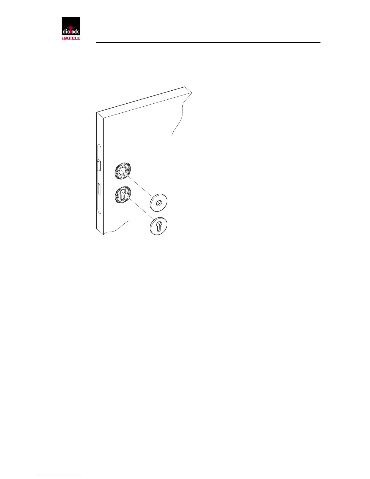
Attaching the rosette fittings
1. Place the ornamental plates of the rosette fittings on the bolting
elements in such a way that they snap into place.
2. Place the door handle on the square spindle in such a way that
the set screws point in the direction of the strike.
3. Tighten the set screws.
4. Install the profile cyclinder, if available.
The rosette fittings have been attached.

Mounting Instructions
42
Setting up the Door Terminal Basic for operation
1. Insert two lithium batteries type ½ AA 3V in the battery
compartment.
Use correct polarity!
(See also "Changing the batteries")
2. Place the lower part of the cover on the bracket in such a way
that the cover guides are located in the ledges of the bracket.
3. Press the upper part of the cover back on the bracket, until it
audibly snaps into place. Take care not to damage the sensitive
plug-in connections.
4. Place the door handles on the external square in such a way that
the set screw points in the direction of the strike.
5. Tighten the set screw.
The Door Terminal Basic has been set up for operation.

Mounting Instructions
43
Disassambly
Tools required:
•
retaining ring pliers
•
screwdriver
•
release lever
•
3 mm Allen wrench
1. Undo the set screws.
2. Remove the door handles.
3. Use the release lever to remove the cover from the bracket.
4. Remove the batteries from battery compartment.
5. Undo the screws in the upper fixing plate.
6. Remove the ornamental plates of the rosette fittings with a
screwdriver.
7. Undo the screws of the bolting elements.
8. Remove the bracket and fixing plate from the outer door leaf.
9. Remove the bolting elements of the rosette fittings from the inner
door leaf.
The Door Terminal Basic has been disassembled.

Mounting Instructions
44
Commissioning
Assigning Programming ADD and DELETE Key-sticks
In the simple operating mode the Programming ADD and DELETE
Key-sticks must be assigned during commissioning.
Attention!
Ö
In order to prevent abuse of the electronic keys by unauthorised
persons: keep Programming ADD and DELETE Key-sticks in a
safe place.
1. Get the green Programming ADD Key-stick and the red DELETE
Key-stick ready.
2. Switch on the Door Terminal Basic by pressing the white button
on the display. The green LED blinks for a few seconds.
3. Hold the green Programming ADD Key-stick in front of the Door
Terminal Basic while the green LED is blinking. The green LED
lights up in confirmation. After removal of the green Programming
ADD Key-stick the red LED blinks.
4. Hold the red Programming DELETE Key-stick in front of the Door
Terminal Basic while the red LED is blinking. The red and green
LEDs light up simultaneously. The Door Terminal Basic switches
off automatically.
If errors crop up during assignment:
Ö Switch on the Door Terminal Basic again.
Ö Assign the Programming ADD and DELETE Key-sticks again.
If errors re-occur:
Ö
Contact the Dialock sales office.

Mounting Instructions
45
Brief operating inctructions
Allocating access rights
1. Switch on Door Terminal Basic : press the white button on the
display. The red LED lights up. The Door Terminal Basic is
switched on.
2. Hold the green Programming ADD Key-stick in front of the
Door Terminal Basic. The green LED blinks.
3. Present the user key to be learned in front of the Door Terminal
Basic within 5 seconds. The green LED lights up solid in
confirmation. Access rights have been granted to the learned user
key.
4. Remove the learned user key.
5. Hold the next user keys in front of the Door Terminal Basic within
5 seconds each time.
After approx. 5 seconds the Door Terminal Basic switches off
automatically.
Withdrawing access rights
1. Switch on the Door Terminal Basic by pressing the white button
on the display. The red LED lights up. The Door Terminal Basic is
switched on.
2. Present the red Programming DELETE Key-stick in front of the
display.
The red LED blinks.
3. Hold the user key to be withdrawn in front of the Door Terminal
Basic . The red LED lights up.
The user key's access rights have been withdrawn.

Mounting Instructions
46
Withdrawing access rights from all user keys
If a user key is lost and should no longer retain its access rights, the
access rights of all user keys must be withdrawn at the Door
Terminal. After this, all the keys that remain and are to have access
rights must be re-authorized/learned again.
1. Hold the red Programming DELETE Key-stick in front of the
display of the Door Terminal Basic. The red LED blinks.
2. Hold the green Programming ADD Key-stick in front of the display
of the Door Terminal Basic. The red LED lights up solid briefly.
The access rights of all the user keys have been withdrawn.
3. All those keys that are to retain access rights must be learned
again to reassign access rights.

Mounting Instructions
47
Operation
Opening the Door Terminal Basic
1. Switch on the Door Terminal Basic by pressing the white button
on the display. The red LED lights up. The Door Terminal Basic is
switched on though the door handle is still uncoupled.
2. Hold an authorized user key a few centimetres (1-3) from the
Door Terminal Basic . The green LED lights up and the red LED
goes out. The coupling of the door handle engages and the door
can now be opened.
If the LEDs do not switch from red to green:
Ö Hold the user key closer to the Door Terminal Basic.
If the red LED goes out without the door opening:
the electronic key does not have access rights.
Ö Open the Door Terminal Basic with a user key that has access
rights.
After approx. 3 seconds the Door Terminal Basic closes
automatically; the door handle is uncoupled.
If Automatic Closing Mode (uncoupling of the door handle) is to be
changed:
Ö
Contact a Dialock technician.

Mounting Instructions
48
Replacement of batteries
When the batteries are weak, the red and green LEDs blink
alternately after the Door Terminal Basic has been switched on. If
the batteries are empty, the door with the Door Terminal Basic can
no longer be locked.
Smooth operation of the Door Terminal Basic is only guaranteed if
weak batteries are replaced immediately. We recommend that the
batteries are changed at least every two years, to prevent any
possible damage being caused by leakage of the batteries.
Do not put batteries in common trash!
Ö
Dispose of batteries in an environmentally friendly manner, e.g. at a
local recycling point.
Changing the batteries
1. Undo the set screws of the door handle on the outside of the
door.

Mounting Instructions
49
2. Remove the door handle from the external square.
3. Press the upper part of the cover against the door leaf to remove
the load from the magnets of the bracket.
4. Place the release lever on the cover from above in such a way
that the back edge of the tool is engaged between the door leaf
and cover and the magnets of the release lever are located above
the magnets of the bracket.
5. Press the upper part of the release lever in the direction of the
door leaf. The upper part of the cover is released from the bracket
and tips forward.
6. Gently raise the lower part of the cover and pull it out of the
guiding rails. The cover is removed from the bracket.
7. Take the empty batteries out of the battery compartment.
8. Insert the new batteries in the battery compartment.
Use correct polarity!
9. Place the lower part of the cover on the bracket in such a way
that the cover guides are located in the rails of the bracket.

Mounting Instructions
50
10. Press the upper part of the cover back on the bracket, until it
audibly snaps into place.
Take care not to damage the
sensitive plug-in connections.

Mounting Instructions
51
11. Place the door handles on the external square in such a way that
the set screw points in the direction of the strike.
12. Tighten the set screw.
The batteries have been changed. The Door Terminal Basic is ready
for operation again.
Emergency opening via the profile cylinder
An emergency opening of the Door Terminal Basic can be carried
out with a key via the profile cyclinder.
1. Loosen and remove the door handles (see 'Changing the
batteries', Steps 1-2).
2. Remove the cover (see 'Changing the batteries', Steps 3-6).
The profile cylinder is accessible so that the emergency opening can
be carried out.

Legal Notice
Any reproduction of these Mounting Instructions, or extracts of it, or
copying of the illustrations and drawings, or copying of the design is
forbidden.
No liability whatsoever is accepted for any printing errors or mistakes
that may have taken place in the production of these Mounting
Instructions.
Delivery terms and technical details are liable to change without
notice.
Status 11.01
Copyright
Sphinx Electronics GmbH & Co KG
Tullastr. 3
D-79341 Kenzingen
Telefon +49 (0) 76 44 / 92 28-0
Telefax +49 (0) 76 44 / 92 28-90
E-Mail: info@sphinx-elektronik.de
Internet: www.sphinx-elektronik.de
 Loading...